WO2013187421A1 - Appareil d'entraînement - Google Patents
Appareil d'entraînement Download PDFInfo
- Publication number
- WO2013187421A1 WO2013187421A1 PCT/JP2013/066124 JP2013066124W WO2013187421A1 WO 2013187421 A1 WO2013187421 A1 WO 2013187421A1 JP 2013066124 W JP2013066124 W JP 2013066124W WO 2013187421 A1 WO2013187421 A1 WO 2013187421A1
- Authority
- WO
- WIPO (PCT)
- Prior art keywords
- user
- training apparatus
- rotation
- fixing means
- training
- Prior art date
- Legal status (The legal status is an assumption and is not a legal conclusion. Google has not performed a legal analysis and makes no representation as to the accuracy of the status listed.)
- Ceased
Links
Images


Classifications
-
- A—HUMAN NECESSITIES
- A63—SPORTS; GAMES; AMUSEMENTS
- A63B—APPARATUS FOR PHYSICAL TRAINING, GYMNASTICS, SWIMMING, CLIMBING, OR FENCING; BALL GAMES; TRAINING EQUIPMENT
- A63B23/00—Exercising apparatus specially adapted for particular parts of the body
- A63B23/02—Exercising apparatus specially adapted for particular parts of the body for the abdomen, the spinal column or the torso muscles related to shoulders (e.g. chest muscles)
- A63B23/0205—Abdomen
- A63B23/0211—Abdomen moving torso with immobilized lower limbs
-
- A—HUMAN NECESSITIES
- A63—SPORTS; GAMES; AMUSEMENTS
- A63B—APPARATUS FOR PHYSICAL TRAINING, GYMNASTICS, SWIMMING, CLIMBING, OR FENCING; BALL GAMES; TRAINING EQUIPMENT
- A63B21/00—Exercising apparatus for developing or strengthening the muscles or joints of the body by working against a counterforce, with or without measuring devices
- A63B21/02—Exercising apparatus for developing or strengthening the muscles or joints of the body by working against a counterforce, with or without measuring devices using resilient force-resisters
- A63B21/023—Wound springs
-
- A—HUMAN NECESSITIES
- A63—SPORTS; GAMES; AMUSEMENTS
- A63B—APPARATUS FOR PHYSICAL TRAINING, GYMNASTICS, SWIMMING, CLIMBING, OR FENCING; BALL GAMES; TRAINING EQUIPMENT
- A63B21/00—Exercising apparatus for developing or strengthening the muscles or joints of the body by working against a counterforce, with or without measuring devices
- A63B21/02—Exercising apparatus for developing or strengthening the muscles or joints of the body by working against a counterforce, with or without measuring devices using resilient force-resisters
- A63B21/04—Exercising apparatus for developing or strengthening the muscles or joints of the body by working against a counterforce, with or without measuring devices using resilient force-resisters attached to static foundation, e.g. a user
- A63B21/0407—Anchored at two end points, e.g. installed within an apparatus
- A63B21/0428—Anchored at two end points, e.g. installed within an apparatus the ends moving relatively by linear reciprocation
-
- A—HUMAN NECESSITIES
- A63—SPORTS; GAMES; AMUSEMENTS
- A63B—APPARATUS FOR PHYSICAL TRAINING, GYMNASTICS, SWIMMING, CLIMBING, OR FENCING; BALL GAMES; TRAINING EQUIPMENT
- A63B21/00—Exercising apparatus for developing or strengthening the muscles or joints of the body by working against a counterforce, with or without measuring devices
- A63B21/02—Exercising apparatus for developing or strengthening the muscles or joints of the body by working against a counterforce, with or without measuring devices using resilient force-resisters
- A63B21/05—Linearly-compressed elements
-
- A—HUMAN NECESSITIES
- A63—SPORTS; GAMES; AMUSEMENTS
- A63B—APPARATUS FOR PHYSICAL TRAINING, GYMNASTICS, SWIMMING, CLIMBING, OR FENCING; BALL GAMES; TRAINING EQUIPMENT
- A63B21/00—Exercising apparatus for developing or strengthening the muscles or joints of the body by working against a counterforce, with or without measuring devices
- A63B21/06—User-manipulated weights
- A63B21/062—User-manipulated weights including guide for vertical or non-vertical weights or array of weights to move against gravity forces
- A63B21/0626—User-manipulated weights including guide for vertical or non-vertical weights or array of weights to move against gravity forces with substantially vertical guiding means
- A63B21/0628—User-manipulated weights including guide for vertical or non-vertical weights or array of weights to move against gravity forces with substantially vertical guiding means for vertical array of weights
-
- A—HUMAN NECESSITIES
- A63—SPORTS; GAMES; AMUSEMENTS
- A63B—APPARATUS FOR PHYSICAL TRAINING, GYMNASTICS, SWIMMING, CLIMBING, OR FENCING; BALL GAMES; TRAINING EQUIPMENT
- A63B21/00—Exercising apparatus for developing or strengthening the muscles or joints of the body by working against a counterforce, with or without measuring devices
- A63B21/40—Interfaces with the user related to strength training; Details thereof
- A63B21/4041—Interfaces with the user related to strength training; Details thereof characterised by the movements of the interface
- A63B21/4049—Rotational movement
-
- A—HUMAN NECESSITIES
- A63—SPORTS; GAMES; AMUSEMENTS
- A63B—APPARATUS FOR PHYSICAL TRAINING, GYMNASTICS, SWIMMING, CLIMBING, OR FENCING; BALL GAMES; TRAINING EQUIPMENT
- A63B23/00—Exercising apparatus specially adapted for particular parts of the body
- A63B23/035—Exercising apparatus specially adapted for particular parts of the body for limbs, i.e. upper or lower limbs, e.g. simultaneously
- A63B23/03516—For both arms together or both legs together; Aspects related to the co-ordination between right and left side limbs of a user
- A63B23/03525—Supports for both feet or both hands performing simultaneously the same movement, e.g. single pedal or single handle
-
- A—HUMAN NECESSITIES
- A63—SPORTS; GAMES; AMUSEMENTS
- A63B—APPARATUS FOR PHYSICAL TRAINING, GYMNASTICS, SWIMMING, CLIMBING, OR FENCING; BALL GAMES; TRAINING EQUIPMENT
- A63B23/00—Exercising apparatus specially adapted for particular parts of the body
- A63B2023/003—Exercising apparatus specially adapted for particular parts of the body by torsion of the body part around its longitudinal axis
-
- A—HUMAN NECESSITIES
- A63—SPORTS; GAMES; AMUSEMENTS
- A63B—APPARATUS FOR PHYSICAL TRAINING, GYMNASTICS, SWIMMING, CLIMBING, OR FENCING; BALL GAMES; TRAINING EQUIPMENT
- A63B21/00—Exercising apparatus for developing or strengthening the muscles or joints of the body by working against a counterforce, with or without measuring devices
- A63B21/40—Interfaces with the user related to strength training; Details thereof
- A63B21/4027—Specific exercise interfaces
- A63B21/4033—Handles, pedals, bars or platforms
- A63B21/4035—Handles, pedals, bars or platforms for operation by hand
-
- A—HUMAN NECESSITIES
- A63—SPORTS; GAMES; AMUSEMENTS
- A63B—APPARATUS FOR PHYSICAL TRAINING, GYMNASTICS, SWIMMING, CLIMBING, OR FENCING; BALL GAMES; TRAINING EQUIPMENT
- A63B2208/00—Characteristics or parameters related to the user or player
- A63B2208/02—Characteristics or parameters related to the user or player posture
- A63B2208/0204—Standing on the feet
Definitions
- the present invention relates to a training apparatus capable of effectively performing strength training of muscles around the trunk and the pelvis to the hip joint.
- a person performing strength training should sit on the seating surface of the device and fix it so that the pelvis does not move, rotate shoulders and chest to twist the upper body, or a person performing strength training may sit on the rotatable seating surface
- a training device and training method that is configured to turn the seat and twist the waist while holding the shoulder and chest stationary.
- An object of the present invention is to provide a training apparatus capable of effectively training not only the trunk but also the peripheral muscles around the hip joint from the pelvis.
- the inventor of the present invention has the training person take a predetermined upright posture so that the upper body including the pelvis is not deformed with the central axis of the body as the rotation center.
- the muscles around the hip joint from the trunk and the pelvis cause contractions such as short contractions, extension contractions, isometric contractions over a wide area, and repeating the rotational movement, the trunk and pelvis
- the inventor of the present invention can easily carry out the repetition of the rotational movement, effectively train the trunk, etc. of the present invention suitable for achieving the object.
- a person who uses the training device of the present invention for the purpose of performing strength training is referred to as a "user".
- the object has a rotation center that allows the user to substantially align the central axes of the body in the upright posture, and can move close to or away from the rotation center Pelvis fixing means, the pelvis fixing means can be rotated about the rotation center, and the pelvis fixing means can be moved up and down in parallel with the rotation center to be positioned at the height position of the user's iliac And a rotating mechanism supporting means for supporting the above.
- the pelvic fixation means can be arranged to press it from the front or back side of the user to the height position of the iliac of the user. Further, the pelvic fixation means can be disposed before and after the user so as to sandwich the height position of the iliac of the user from the front and back. Alternatively, at least two of the pelvic fixation means can be configured as a pair so as to be in the shape of a half in a plan view or in left-right symmetry.
- the term "C-shaped" usually refers to a state in which at least two pelvic fixation means are horizontally connected if necessary and arranged in a C-shape as viewed from above (Same below).
- the term "left-right symmetry" refers to the pelvic fixation means as a set of at least two arranged in a horizontal direction or a vertical direction or both around a front-back direction passing through the rotation center as viewed from the user It refers to a state in which it is symmetrical, and is a concept including the above-mentioned “C-shaped” (the same applies hereinafter).
- the pelvic fixation means configured in one set of such a configuration may be arranged to be pressed from the front side or the rear side of the user, and configured as one set so as to sandwich from the front and back of the user
- the pelvic fixation means may be respectively disposed before and after the user.
- the pelvis fixing means may further include an upper body support above the upper body for restricting the movement of the upper body of the user. The pelvis fixation means can be moved close to and away from the rotation center.
- the rotation mechanism support means includes a rotation mechanism portion configured to be able to rotate the pelvis fixing means around the rotation center, and a support means that can be aligned by moving the rotation mechanism portion up and down in parallel with the rotation center.
- the rotation mechanism unit includes, for example, a rotary disk and a rotary disk supporting means for rotatably supporting the rotary disk, and the rotary disk has a diameter from a part of the outer periphery of the disk-like body in plan view through the center It may have a substantially horseshoe-like shape in a plan view in which a notch approaching the outer periphery on the opposite side of the direction is formed.
- the rotating mechanism unit also includes a rotating disk and a rotating disk supporting means for rotatably supporting the rotating disk, and the rotating disk penetrates the front and back substantially concentrically in the central region of the rotating disk and the user's You may comprise so that it may exhibit a planar view donut shape in which the penetration hole which can penetrate
- the rotation mechanism and the support means may be independent of each other, and the former may include some or all of the components of the latter. Further, the component group that enables the pelvic fixation means to move in and out may be independent of each other with the rotation mechanism and the support means, and a part or all of the component group that can move in and out. May be included in the rotation mechanism, the support means, or both.
- the rotating disc support means may be provided with a braking means for applying a braking force to the rotating disc. Further, the rotating disk support means may include a load adjusting device capable of adjusting the load applied to the rotating disk when the rotating disk is rotated. The load adjusting means applies a load to the rotation of the rotary disc from right to left or from left to right as viewed from the user without switching the load application direction. preferable.
- the rotation mechanism unit also supports the pelvis fixing means at an end portion on the rotation center side of the traveling body and an arc-shaped rail centered on the rotation center, a traveling body traveling along the rail, and the rotation center side of the traveling body. It is also possible to constitute from the guide which supports the movable body slidably.
- the rotation mechanism portion includes a guide portion which is a part of a component that allows the pelvis fixing means to move in contact with and separate from each other. It is preferable to provide a stopper for restricting the traveling of the traveling body at both ends of the rail.
- a pair of guide members are disposed at both ends in the width direction of the guide portion, and the movable body has both side edges fitted in the guide grooves provided on the surfaces facing each other, thereby It can be configured to slide in the radial direction.
- the cross section in the direction orthogonal to the slide movement direction of the guide groove is formed substantially in a V shape, and the cross section in the same direction of both side edges of the movable body can be formed in an arc shape by bulging outward.
- the guide member is preferably formed of a plastic material.
- the rotation mechanism unit may include braking means that exerts a braking force on the traveling body respectively near both end portions of the rail.
- the braking means includes an elastic body, and the biasing force of the elastic body, which increases in inverse proportion to the approach distance of the traveling body to the stopper, can be used as the braking force.
- the rotation mechanism unit may include a load adjusting unit capable of adjusting a load applied to the traveling body when the traveling body travels.
- a spindle whose axial center is aligned with the center of rotation is erected, and at its upper end portion, a rotating body portion formed so that the user sandwiches it with a knee May be provided rotatably around the rotation center.
- the foot of the user who is in the upright position is provided with an inclined surface that slopes upward from the user's heel to the toe, or a display is provided to remind the user to place the legs in a crotch condition
- the display may be provided on the inclined surface.
- a rod-like body in which the user can place the front area of both feet substantially parallel to the user's forehead plane in front of the user's feet, the rotation center and the rotation mechanism support means It may be arranged to be movable back and forth, and the user may place the front area of both feet on the rod-like body so as to incline upward from the user's heel to the toe.
- the object has a rotation center that allows the user to substantially align the central axes of the body in the upright posture, and the user rests in the posture.
- a base having a rotary table rotatable around a rotation center, a pelvis fixing means capable of moving in and out of contact with the rotation center, and the pelvis fixing means supported vertically movably in parallel with the rotation center.
- the invention is achieved by a training device characterized in that it comprises support means capable of aligning the pelvic fixation means at the height position of the ilium of the person.
- the pelvic fixation means can be arranged to press it from the front or back side of the user to the height position of the iliac of the user. Further, the pelvic fixation means can be disposed before and after the user so as to sandwich the height position of the iliac of the user from the front and back. Alternatively, at least two of the pelvic fixation means can be configured as a pair so as to be in the shape of a half in a plan view or in left-right symmetry. The pair of pelvic fixation means having such a configuration may be arranged to be pressed from the front or back side of the user, and the pair of pelvic fixation is arranged to be pinched from the front and back of the user Two sets of means may be respectively disposed before and after the user. In addition, the pelvis fixing means may further include an upper body support above the upper body for restricting the movement of the upper body of the user.
- the training apparatus comprises: a rotation center which allows the user to stand upright and to substantially align the central axis of the body, a pelvis fixing means for fixing the height position of the ilium of the user, and the pelvis fixing means Since the rotation mechanism support means is provided to rotate around the rotation center according to the height position of the user's ilium, the user repeatedly rotates the upper body including the pelvis so as not to deform the upper body. Training can be performed easily and in a short time. As a result, it is possible to effectively train the muscles around the trunk and the pelvis and hip joints, to strengthen and stabilize the trunk, to increase abdominal pressure and to achieve slimness (size down) around the waist, and posture You can also arrange
- FIG. 3 is a plan view of the embodiment shown in Figure 2; It is a top view of the base of embodiment shown in FIG.
- FIG. 3 is a front view and a side view of the embodiment shown in FIG. 2;
- FIG. shows the support state of the turntable by a turntable support means.
- FIG. 1 It is a figure which shows an example of a damping
- FIG. 19 is a front view of the embodiment shown in FIG. 18; FIG. 19 is a rear view of the embodiment shown in FIG. 18; FIG. 19 is a left side view of the embodiment shown in FIG. 18; FIG. 19 is a plan view of the embodiment shown in FIG. 18; FIG. 21 is a view on arrow AA in FIG. 20. It is a figure explaining the structure and operation
- the term “user” shall refer to the implementer of the strength training using the training apparatus of this invention.
- the terms “right” or “left” are used in the sense of right, left as viewed from the user.
- the terms “rightward” or “leftward” will be used in the sense of the direction as viewed from the user, and the description of "as viewed from the user” will be omitted.
- the term “rotational mechanism” is used to restrict, stop, and load the rotation of the pelvis fixation means, as well as the components that work to rotate the pelvis fixation means about the rotation center.
- rotation is used in the sense to include alternating rotation in both directions, as well as clockwise or counterclockwise rotation in the horizontal direction.
- the user H opens his legs in an upright posture such that his or her pelvis is opened from the pelvis width to the shoulder width and the center axis of the body is substantially aligned with the rotation center 3 of the device.
- the term "central axis of the body” means the user H's own right and left ears, the centers of the left and right shoulders, the front of the first lumbar spine, the centers of the left and right hips, left and right when viewed from the side
- the central sagittal plane passes through all the points when the upright posture is taken so that each point of the center of the knee and the front ends of the left and right ankles are aligned vertically and preferably vertically.
- Left-right symmetry means a line (axis) that intersects with the body in the middle of the body (a plane that divides the body equally) (this body's central axis is sometimes called the vertical axis).
- this body's central axis is sometimes called the vertical axis.
- a quadrangle ABCD connecting the positions A and D of the base of both shoulders of the user H and the positions B and C of the outermost edges of the iliacs on both sides of the pelvis is formed on the upper body.
- rotation center also includes an imaginary line extending vertically upward from the rotation center of the training device of the present invention.
- the user H presses the pelvic fixation means 4 from the front side to the height position of the iliac of the user, and makes the pelvis stand further.
- the user H uses the upper body including the pelvis (lower abdomen and waist) so as not to deform (bent, twist, etc.) the above-mentioned quadrilateral ABCD in that state and to prevent the central axis of the body from swinging from the rotation center 3
- the abdominal transverse muscle abdominal rectus muscle, external oblique muscle, internal oblique muscle, intestine Lumbar muscles (Lumbar muscles, small lumbar muscles, iliac muscles), Lumbar square muscles, iliac crest muscles, multifibular muscles, erector spinae muscles, iliac muscles, middle gluteus muscles, as well as the pelvis Peripheral muscles around the hip joint cause
- the pelvis fixation means 4 corresponds to the pelvis fixation means 4 and 57 in the first and third embodiments. Furthermore, the pelvic fixation means 4 can be used as in the pair of pelvic fixation means 46, 46; 73, 73 in the second embodiment or the fourth embodiment by changing the size as appropriate.
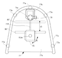
- FIG. 2 is a perspective view showing a first embodiment of the training device of the present invention
- FIG. 3 is a plan view of the first embodiment.
- FIG. 4 is a plan view of the base portion of the first embodiment
- FIG. 5 is a front view (FIG. 5 (a)) and a side view (FIG. 5 (b)) of the first embodiment.
- the training device 1 of this embodiment has a pelvis fixing means 4 rotatable around the rotation center 3 in the device, and the pelvis fixing means 4 can rotate it, and the height of the ilium of the user H.
- a rotation mechanism support means 2 which supports in an adjustable position.
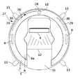
- the rotation mechanism support means 2 includes a rotary disc 6 and a rotary disc support means 7 for rotatably supporting the rotary disc 6 in plan view and a substantially horseshoe-shaped rotational mechanical part 5, and the circumferential direction of the surface from the peripheral edge of its lower surface.
- Of four columns 14, 14, 14, 14 as support means extending downward at regular intervals, and a flat surface mounted on the floor and supporting and fixing the lower ends of the columns 14, 14, 14, 14 It is mainly composed of a base 11 having a circular view shape.
- the center of rotation 3 causes the user H to substantially align the central axes of the body, takes a predetermined upright posture, and does not deform the quadrilateral ABCD shown in FIG. It is a reference in performing an exercise to rotate the upper body including (lower abdomen and waist), and is an important element in the training device 1 of the present invention.
- the user H uses the training apparatus 1 according to the present embodiment, the user H is placed on the base 11 and rotates the upper body including the pelvis (lower abdomen and waist) in the left and right direction by himself
- a mirror or the like may be installed near the training device 1 so that the user H can adjust.
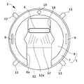
- the rotation mechanism unit 5 includes a rotary disc 6 having a substantially horseshoe shape in a plan view, and a rotary disc support means 7 rotatably supporting the rotary disc 6 at its circumferential portion.
- the rotary disc 6 is formed in a substantially horseshoe-like shape in a plan view in which a notch 6a is formed to approach the outer periphery on the opposite side in the diameter direction from a part of the outer periphery through the center thereof.
- the width in the direction perpendicular to the direction in which the cut 6a is provided is set to allow the user H to go straight toward the center of the rotary disc 6 without an obstacle in the cut 6a (for example, about 460 mm). ). This width can be changed as appropriate.
- the rotary disk 6 has a substantially disc shape so that the rotary disk support means 7 rotatably supports the circumferential portion thereof (even if the rotary disk itself has a rotation shaft, it is not provided.
- a through hole through which the user H's body passes is provided, and the central axis of the body is configured to substantially coincide with the center of rotation 3
- the shape is not limited to the above.
- the rotating disk 6 is a donut shaped body in a plan view in which a through hole having a substantially circular shape in plan view is formed in a central region thereof to penetrate the front and back substantially concentric with the center and penetrate the body of the user H. You may form.
- the central region of the upper surface of the rotating disk 6 it is possible to provide a sign indicating how much the user H is rotating in the right or left direction.
- the sign may also include an indication of the position of the unrotated state.
- the pelvis fixing means 4 in the present embodiment has an external shape of a substantially rectangular parallelepiped (substantially square pole), and is a surface pressed against the height position of the ilium of the user H (hereinafter referred to as a contact surface) Is made of a soft material.
- the external shape of the pelvis fixing means 4 is not limited to a substantially rectangular parallelepiped, and can be appropriately selected and adopted from various known three-dimensional shapes. As a specific example of such a known three-dimensional shape, a curved plate-like body etc. other than a substantially cylindrical shape, a substantially elliptic cylinder shape, etc. are mentioned, for example.
- the pelvic fixation means 4 may have a separable structure in several parts.
- the front surface may be formed by the longitudinal or lateral arrangement of at least two cylinders or prisms.
- the pelvic fixation means 4 has a contact surface that is horizontal to the lower abdomen or waist of the user H so that the contact area can be easily enlarged and brought into contact when the pelvic fixation means 4 is pressed against the height position of the ilium of the user H According to the external shape of the direction, it can be formed in a concave shape from both side edges toward the middle area. Furthermore, when pressing the pelvis fixing means 4 from the front side to the height position of the user's H arm, the region closer to the upper end of the abutment surface is closer to the rotation center 3 than the region closer to the lower end. It can also be formed to come. For example, the case where the surface on the user H side is inclined with respect to the vertical direction to be formed downward may be mentioned. Thereby, the user H can keep his pelvis upright by pressing the height position of the ilium against the entire surface of the contact surface of the pelvic fixation means 4.
- the size of the pelvis fixing means 4 there is no particular limitation on the size of the pelvis fixing means 4, but the use of the training apparatus of the present invention for rotating the upper body including the pelvis (lower abdomen and waist) so that the user H does not deform the upper half square ABCD (see FIG. 1)
- the size when the outer shape is a substantially rectangular parallelepiped, it can be set to about 130 to 200 mm in length (vertical direction) (165 mm as an intermediate value), 340 to 400 mm in width (horizontal direction) (intermediate value 370 mm), and a depth of about 80 to 200 mm.
- the pelvic fixation means may be combined in the vertical and horizontal directions to form the size substantially equal to the size as a whole.
- two poles can be erected perpendicularly to the surface as upper body supporting portions from the side edge of the upper surface thereof.
- the pelvic fixation means 4 at the height position of his iliac, as shown in the figure, whether he holds or attaches his hand to each of the two poles 41, 42 1 can be fixed so as not to deform the upper quadrilateral ABCD shown in FIG. 1, and the central axis of the user H's body is from the center of rotation 3 during rotational movement of the upper half including the pelvis (lower abdomen and waist) Since it is possible to suppress swinging out, muscle training of a predetermined site can be performed more effectively.
- the upper body supporting portion is not particularly limited to the configuration including the two illustrated poles 41 and 42 as long as the upper body can be fixed as described above, and one pole or a plate having an appropriate width and thickness is used.
- arms are provided so as to project further forward from the both side edges of the upper surface of the pelvic fixation means 4 in the same manner, and the arms are held by both hands by the user H It can be used suitably.
- a device that can be mechanically fixed so as not to deform the quadrangle ABCD (see FIG. 1) of the upper half of the user H can be used as the upper body support or attached to the upper body support. a device that can be mechanically fixed so as not to deform the quadrangle ABCD (see FIG. 1) of the upper half of the user H can be used. .
- the pelvis fixing means 4 is attached to the lower surface of the rotary disc 6 so as to be able to move close to and away from the rotation center 3 in the notch 6 a of the rotary disc 6.
- FIG. 7 shows an example of the attachment state of the pelvis fixing means 4 on the lower surface of the rotary disc 6.
- the lower side the opening side of the notch 6a of the substantially horseshoe-shaped rotary disc 6 toward this figure
- the upper side back side of the notch 6a
- shafts 16 and 16 are respectively extended in the width direction of the incision 6a from both side surfaces thereof, and sheath tubes 17 and 17 are provided in the direction orthogonal to the shaft 16 at each tip.
- One end of the opening direction is fixed.
- a locking portion 18 is provided on one of the two sheath tubes 17 near the other end of the sheath tube 17 in the opening direction.
- a pair of guide rails 19, 19 provided with stoppers 191, 191 at both ends are provided parallel to each other along the back side edges of the notch 6a.
- Sheath tubes 17, 17 on both sides of the pelvis fixing means 4 are externally fitted to the pair of guide rails 19, 19, respectively.
- the pelvis fixing means 4 is slidable along the guide rails 19, 19 so as to approach or separate from the rotation center 3 (here, the combination of the guide rail 19 and the sheath tube 17) , Slide movement mechanism).
- the cross section of the guide rail 19 can be formed into a known shape such as a circle, an ellipse, a rectangle, or a square, and the outer shape of the sheath tube 17 externally fitted thereto can be changed according to the cross section.
- the pelvis fixing means 4 is movably connected to the guide rail 19 via the shaft 16 and the sheath tube 17 as described above, but the present invention is not limited thereto.
- the belt 4 may be attached to the guide rail 4 and be movably connected to the guide rail by belt tightening.
- the pelvis fixing means 4 can be stopped and fixed at an arbitrary position on the guide rail 19 (e.g., a position 4 ').
- the locking portion 18 can be appropriately selected and used from those having a conventionally known structure.
- a pin (not shown) is provided in the locking portion 18 to be moved in and out by operating the locking portion 18, and a structure in which a plurality of pin holes into which the pins are fitted is arranged on the side surface of the guide rail 19 The structure etc. which press the side of the guide rail 19 are mentioned.
- the pelvic fixation means 4 is pressed only from the front side to the height position of the ilium of the user H
- a pelvic fixation means having a similar external shape and size is pressed against the height position of the ilium from the rear side, or a pelvic fixation means comprising at least two pairs is prepared. It may be configured to be inserted at the height position of the ilium from the front and back of the user H by the fixing means.
- the slide movement mechanism of the pelvis fixing means includes a pair of guide rails 19 shown in FIG. The same configuration as the configuration using 17 and 17 can be adopted.
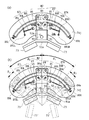
- the rotary disk support means 7 in the present embodiment has a width of the cut 6 a in the rotary disk 6 from a substantially donut shape in a plan view and a substantially rectangular cross section in a direction perpendicular to the circumferential direction. It has a shape in which the arc portion is cut out by approximately the same amount as that in the above.
- the rotating disk support means 7 is configured of a housing 72 and a lid 71. Openings 8 are formed in the circumferential direction on the two end faces (see FIG. 2, reference numerals 7a and 7a) formed by the cutting from the inner surface of the rotating disk support means 7. As shown in FIG.
- the shape of the housing 72 and the lid 71 can be set so that the opening 8 is formed by attaching the lid 71 to the upper part of the housing 72.
- the circumferential portion of the rotary disc 6 is accommodated in the opening 8 (see FIG. 2), and the hollow inside is a storage chamber 8a of the circumferential portion of the rotary disc 6 (see FIG. 8).
- the circumferential portion of the rotary disk 6 accommodated in the rotary disk support means 7 is supported by bearings 24 and 22 on its lower surface and circumferential end surface, respectively.
- the bearings 24 and 22 have their axes 24 a and 22 a rotatably supported by pivot supports 25 and 23 attached to the bottom surface and the outer wall inner surface of the housing 72.
- the upper surface of the circumferential portion of the rotating disk 6 is supported so as to be pressed from above by a bearing 20 rotatably mounted on the lid 71 side.
- the bearing 20 is also rotatably supported by a shaft support 21 attached to the top plate inner surface of the lid 71 with a shaft 20 a included in the bearing 20.
- each of the bearings 20, 22 and 24 may be lined with rubber, resin or the like to prevent frictional noise with the rotary disc 6.
- the bearings 20, 22 and 24 described above can be substituted by rollers each having an axis. Also with this roller, a lining such as rubber can be provided on the outer peripheral surface thereof.
- the outer shell of the turntable support means 7 is constituted by the lid 71 and the housing 72,
- the rotary disc 6 is set so that its circumferential portion is accommodated in the housing 72 without covering the lid 71, and the lid 71 is covered thereon
- the assembly work of the training device of this embodiment can be made more efficient.
- FIG. 9 shows the arrangement of bearings in the rotary disk support means 7 and the support of the rotary disk 6 by the bearings.
- the bearing 24 shown in FIG. 8 is also provided at the corresponding position of the bearing 20 on the back surface side of the rotary disk 6.
- nine bearings 20, 22 and 24 are arranged at intervals of about 30 degrees in the circumferential direction of the rotary disk 6, and a total of 27 bearings rotatably support the rotary disk 6.
- the arrangement of the bearings 20, 22 and 24 (the distance between the adjacent bearings, and the number and arrangement of the bearings) is not limited to the example of arrangement shown in FIG. it can. Further, the bearing indicated by reference numeral 20 or the like can be substituted by a rotating wheel or the like having the same function as this.
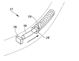
- FIG. 10 schematically shows an example of a braking means that applies a braking force to the rotating disk 6.
- reference numeral 27 is a braking means
- 28 is a projecting piece
- 29 is a braking cylinder
- 30 is a rod portion thereof.
- a compression coil spring for biasing the rod portion 30 in the projecting direction is accommodated.
- FIG. 11 is a view for explaining the installation of the braking means 27 shown in FIG. As shown in this figure, it is necessary to install the projection 28 at a predetermined position near the circumference of the rotary disk 6, and to apply the braking force to the rotary disk 6 along the movement line of the projection 28 for the braking cylinder 29. (A specific configuration is shown in FIG.
- the projecting piece 28 moving with the rotation of the rotary disk 6 collides with the tip of the rod portion 30 projecting from the braking cylinder 29 fixed in the housing 72, whereby the brake for rotation of the rotary disk 6
- the compression coil spring inside the braking cylinder 29 contracts by an appropriate length, the rotation of the rotary disk 6 is stopped.
- the braking means 27 is provided to prevent injury or accident due to hyperextension of the human body due to excessive rotational movement.
- FIG. 12 shows an example of the rotation range of the rotary disc 6 when the braking means 27 shown in FIG. 10 is used.
- the braking means 27 shown in FIG. 10 when rotating in the right direction, from the position before rotation (in the figure, the position where the direction of the cut 6a matches the line segment OP formed by a one-dot chain line),
- the center line of the notch 6a of 6 is rotated by the rotation angle ⁇ 1
- the projecting piece 28 contacts the tip of the rod portion 30 of the braking cylinder 29, and the rotation limit angle against the biasing force of the spring in the braking cylinder 29.
- the retraction limit of the rod portion 30 is reached and the rotating disk 6 can not rotate any more.
- the rotary disc 6 can freely rotate from the position before rotation to the rotational angle ⁇ 1, and when it exceeds the rotational angle ⁇ 1, the rotation of the rotary disc 6 is braked and the rotational limit angle ⁇ 2 is reached.
- the board 6 will stop.
- the rotation angle ⁇ 1 and the rotation limit angle ⁇ 2 can be set as appropriate.
- the rotation angle ⁇ 1 in FIG. 12 can be set to about 40 degrees
- the rotation limit angle ⁇ 2 in FIG. 12 can be set to about 50 degrees.
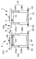
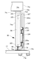
- FIG. 13 is a cross-sectional view showing an example of the load adjusting means and the operation thereof, in which (a) shows the state before the load adjustment and (b) shows the state after the load adjustment.
- the load adjusting means 10 in the example shown in this figure is composed of a knob 31 and a case 32 fixed to the lid 71 of the rotating disk supporting means 7 in a penetrating manner. The attachment of the case 32 to the lid 71 is not particularly limited to such a configuration.
- the knob 31 includes a shaft 31a accommodated in the case 32, and at an intermediate position of the shaft, a pin 31b is provided which protrudes in a direction perpendicular to the axial direction.
- the upper portion 33 in the case 32 has an opening at the center through which the knob shaft 31a is inserted, and the inner wall of the opening is provided with a pin receiving portion 34 capable of receiving pins at four height positions. There is.
- the pin receiving portion 34 enables four-stage load adjustment (the load adjustment is not limited to four stages, and may be three or five or more stages).
- Below the upper portion 33 of the case an inner cylinder 35, a spring 36, and a bearing portion 37 having a load bearing 38 rotatable at the lower end portion are disposed in this order.
- the load bearing 38 is in a state of simply pressing the rotary disc 6 from the upper side without receiving any biasing force of the spring 36.
- the knob 31 is pushed down, and the pin 31b is accommodated in the lowermost pin receiving portion 34.
- the shaft 31a of the knob 31 pushes down the inner cylinder 35, the spring 36 is contracted, and the load bearing 38 further pushes the rotary disc 6 in an attempt to restore, and the rotary disc 6 is loaded. It will rotate.
- the user H has to perform the rotational movement in the state of receiving stronger resistance, which enables effective strength training.
- the load bearing 38 can be substituted by a rotating wheel or the like having the same function as this.
- a training apparatus or exercise apparatus configured to twist the upper or lower body described in the background art uses weights, plates, pneumatics, hydraulics, etc. to apply a load during the rotational movement.
- weight type, plate type and pneumatic type when switching the rotational movement from right to left or from left to right, switching of the direction in which the load is applied by the load adjustment device I needed to do it. Therefore, there is also a problem that it is not possible to exercise with a constant load continuously during the rotational movement from the right to the left or from the left to the right.
- the hydraulic device there is also a problem that the magnitude of the load resistance is different between the rightward rotational movement and the leftward rotational movement.
- the rotation mechanism unit 5 is supported at a predetermined height by four columns 14, 14, 14, 14 as support means, as shown in FIGS. 2 and 5.
- the respective inner cylinders 14a are configured to be able to move up and down with respect to the outer cylinder 14b, the user H can move the pelvis fixing means 4 up and down to the height position of his own iliac according to his / her height. It can be moved (lifted).
- the elevation is performed by the user H operating the elevation lever 15.
- the elevating mechanism include a gas spring, a pneumatic cylinder, a hydraulic cylinder, a ratchet, and an electric actuator. It is possible to suitably use conventionally known ones in which they are expanded and contracted by being incorporated in the columns 14 and operating the raising and lowering levers 15.
- pillar can be set suitably, and are not limited to this embodiment.
- shape of the lifting lever 15 is not particularly limited to the illustrated shape. A foot switch, a button or the like can be used instead of the lifting lever 15.
- the base 11 is a short columnar body having a substantially circular shape in plan view, and the pillars 14, 14, 14, 14 (outer cylinders 14 b, 14 b, 1 b) are provided near the circumference of the surface as described above. , 14b) are fixed, and in the central region thereof, a tilt table 12 is provided.
- the tilt angle of the tilt table 12 can be configured to be able to be adjusted continuously or intermittently within a settable angle range such as 0 to 25 degrees. In the case of a configuration in which the inclination angle is adjusted intermittently, it is preferable to be able to adjust in three steps of 5, 10 and 15 degrees, for example (this set angle and the number of steps can be set as appropriate).
- the direction display 12a of the foot which warns the direction of a foot is provided in the inclined surface of this inclination stand 12 so that the user H may turn both feet inward and make it an inside crotch.
- the user H can more effectively carry out the strength training.
- it is effective in the muscular strength training of the user H, even if only one of the inclination stand 12 and the direction display 12a of a leg
- Overturn prevention devices 13, 13, 13, 13 are provided on the base 11 at four places at equal intervals in the circumferential direction on its side surface. Further, below the overturn preventing devices 13, 13, 13, 13 there is provided a known leveling device for horizontally installing the training device of the present embodiment. In addition, the number of objects and arrangement
- positioning of the fall prevention apparatus 13 are not limited to the example of illustration, It can set suitably.
- FIG. 15 is a perspective view showing a second embodiment of the training device of the present invention.
- a base 52 having a rotary table 53 at the center of the upper surface, connecting portions 51, 51 provided on the upper surface so as to sandwich the rotary table 53, and the connecting portions 51, 51.
- the arms 48 and 49 which can be pivoted in one direction, which are erected opposite to each other, the coupling portions 47 and 47 respectively provided on the upper end portions thereof (the above configuration is the rotation mechanism support means 45, and pelvic fixation means 46, 46 pivotally coupled in one direction by these coupling portions 47, 47 by these.
- the training device 44 of this embodiment is configured to fix the pelvis of the user H by the pair of pelvis fixing means 46, 46 at the tip of each of the arms 48, 49, and to rotate the rotary table 53 provided on the base 52.
- the second embodiment differs from the first embodiment in which one pelvic fixation means 4 is configured to be rotatable.
- the rotary table 53 is configured to be rotatable in the right direction and the left direction.
- the rotation mechanism of the rotary table 53 preferably includes various known load adjusting means for adjusting the load applied to the rotation, and various known braking means for restricting the rotation range.
- the pair of opposing arms 48, 49 rotate so as to move toward and away from each other by the rotatable connection portions 51, 51 in one direction.
- the longitudinal middle regions of these arms 48 and 49 be configured to be extensible.
- the pair of pelvic fixation means 46, 46 may have the same outer shape and structure as the above embodiment. Further, the upper body support (not shown) in the embodiment can be provided in one of the pair of pelvic fixation means 46 (see FIG. 6, reference numerals 41 and 42). Thereby, the user H not only prevents the quadrangle ABCD shown in FIG. 1 from being deformed more reliably during the rotational movement, but also the user during the rotational movement of the upper body including the pelvis (lower abdomen and waist) Since it is possible to prevent the central axis of the body H from swinging out of the rotation center 3, it is possible to perform strength training on a predetermined site more effectively.
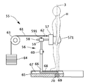
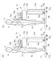
- FIG. 16 is a perspective view showing a third embodiment of the training device of the present invention
- FIG. 17 is a view showing a state of use thereof.
- a pelvis fixing means 57 provided with a band-like fastener 571 and a rotation that supports it rotatably around the rotation center 3 and can be vertically aligned. It comprises the mechanism support means 56.
- the rotation mechanism support means 56 is, in the rotation mechanism storage chamber 67 in the base 65, a rotation shaft 69 erected rotatably around the rotation center 3 by the shaft support portion 70, and one end portion is fixed to the upper end thereof
- the horizontal member 68 extending in a direction substantially orthogonal to the rotation shaft 69, and an arc-shaped elongated hole 66, and is erected from the vicinity of the other end of the horizontal member 68 perpendicularly to the outside of the rotation mechanism housing 67;
- the support column 60, a rectangular cylindrical guide portion 59 provided at the upper end thereof, and a stay 58 movable in the opening direction in the opening of the guide portion 59 are provided.
- Guide part 59 should just be cylindrical, and is not limited to the above-mentioned square cylindrical shape.
- a combination of the guide portion 59 and the stay 58 which makes the pelvic fixation means 57 move in contact with and separate from each other constitutes a slide movement mechanism.
- the slide movement mechanism is included in the rotation mechanism support means 56.
- the stay 58 is a square member provided substantially vertically from the center of the back surface of the pelvis fixing means 57.
- the outer shape of the stay 58 is not limited to this, and can be appropriately changed according to the shape of the opening cross section of the guide portion 59.
- the guide portion 59 is externally fitted to the stay 58. By operating the knob 591 of the guide portion 59, the stay 58 in the opening direction of the guide portion 59, and further, the slide movement of the pelvis fixing means 57 is enabled or regulated.
- the guide portion 59 may be of any known structure without particular limitation.
- the support 60 has an extendable structure including an outer cylinder and an inner cylinder which can be nested therein, thereby raising and lowering the pelvis fixing means 57 up and down to allow the user's H iliac to move. Positioning is possible at the height position of (lifting mechanism). From the upper surface of the pelvis fixing means 57, two poles as shown in FIG. 6 and reference numerals 41 and 42 may be provided as the upper body support.
- the pelvis fixing means 57 can be rotated with the rotation of the rotation shaft 69.
- the rotation range of the pelvis fixing means 57 is determined by the length of the arc of the arc shaped long hole 66 of the base 65.
- the column 60 being rotated using a device such as the braking means 27 in the first embodiment It is preferable not to collide with the end of the arcuate long hole 66.
- the load adjusting means as shown in FIGS.
- one end of a wire 61 is connected to the upper end center of the back surface of the pelvis fixing means 57 and a pulley 62, 62 and a pulley disposed in the middle
- the other end connected to the weight 64 via 63 can be used.
- the load adjusting means switches the load application direction in either the right direction or the left direction as viewed from the user H It is possible to put the same load without.
- the load adjusting means is not limited to such an example, and a conventionally known structure can be used.
- the user H adjusts the weight of the weight 64 in the load adjusting means in advance. Subsequently, the user H takes an upright posture, makes the central axis of the body substantially coincide with the rotation center 3, and operates the knob 591 of the guide portion 59 to set the pelvic fixation means 57 to the height of the ilium. Press to the position. At the same time, the band-like fastener 571 is tightened to bring the height position of the iliac into close contact with the pelvic fixation means 57.
- the central axis of the body of the user H is the center of rotation 3 during rotational movement of the upper body including the pelvis (lower abdomen and waist) so as not to deform the quadrangle ABCD (see FIG. 1) shown in FIG. Rotate the upper body including the pelvis (lower abdomen and hips) rightward and leftward so that it does not swing out of the body. Repeating this exercise enables effective strength training.
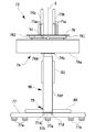
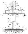
- FIG. 18 is a perspective view showing a fourth embodiment of the training device of the present invention.
- 19 is a front view
- FIG. 20 is a rear view
- FIG. 21 is a left side view
- FIG. 22 is a plan view
- FIG. 23 is a view on arrow AA in FIG.
- FIG. 24 illustrates the configuration and operation of one example of the rotation mechanism unit of the present embodiment, (a) is a plan view showing the configuration, (b) is an explanatory view of the operation (rotation range) is there.
- FIG. 25 shows the structure and operation of one example of the slide mechanism, and (a) is a plan view showing the structure, and (b) is a sectional front view. Furthermore, FIG.
- FIG. 26 is a partial cross-sectional side view for explaining the configuration of an example of the elevation mechanism.
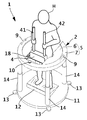
- FIG. 27 is a figure which shows the example of use condition of 4th Embodiment, (a), (b) has shown the example of the variation of the upper-body support part which the user H can select.
- the components attached to the components in addition to the components that work to move the pelvis fixing means toward and away from the rotation center, the components attached to the components.
- the training device 72 of the present embodiment is provided on the pelvis fixing means 73, 73 and the base 77, and can rotate the pelvis fixing means 73, 73, And the upper end portion of a pivot mechanism support means 74 supported so as to be positionally positionable at the height position of the ilium of the user H, and a support shaft 811 vertically disposed concentrically with the rotation center 3 on the base 77 as well. It mainly comprises the rotating body portion 81 provided.
- the rotation mechanism support means 74 will be described first.
- the rotation mechanism support means 74 is A rotation mechanism 82 for rotating the pelvis fixing means 73, 73 around the rotation center 3; A slide mechanism 95 for movably moving the pelvis fixing means 73 and 73 with respect to the rotation center 3; It includes an elevation mechanism portion 96 capable of positioning by vertically moving the rotation mechanism portion 82 and the slide mechanism portion 95 in the vertical direction.
- the elevating mechanism unit 96 corresponds to a support means (the columns 14, 14,... In the first embodiment).
- a pair of pelvic fixation means 73, 73 is disposed in a substantially C shape in plan view.
- Each of the pelvic fixation means 73 is a substantially rectangular parallelepiped (approximately square pole) having an appropriate outer thickness such as a rectangular or square outer diameter shape, and is pressed against the height position of the user H's ilium.
- the contact surface is formed of a soft material.
- the thickness of the pelvic fixation means 73 is usually about 30 mm.
- the outer shape of the pelvis fixing means 73 is not limited to a substantially rectangular parallelepiped, and can be selected appropriately from among various known outer shapes.
- the individual pelvic fixation means 73 may also be provided with separable structures in several parts.
- the front surface may be formed by the longitudinal or lateral arrangement of at least two cylinders or prisms.
- a configuration is adopted in which at least two pairs of pelvic fixing means 73, 73 are used in a square shape in a plan view, but the present invention is not limited to this.
- a pelvic fixation means having a configuration in which the pelvic fixation means is pressed from the front side or the back side to the height position of the ilium of the user H
- a configuration may be adopted in which the user H's position is placed in front of and behind the user H, and the height position of the user H's iliac is inserted from the front and back.
- the pelvic fixation means on the rear side newly needs means for supporting the same, but for example, one having the same configuration as the rotation mechanism support means 74 is installed on the rear side of the user H You may do so.
- the pelvic fixation means 73, 73 according to the present embodiment may be arranged so as to be laterally symmetrical with respect to the user H, in addition to arranging them in a square shape in plan view.
- the rotation mechanism portion 82 shown in FIG. 24 is a rail 83 in the shape of an arc in plan view, and a plate-like body in the shape of a rectangle in plan view.
- Two pulleys 85 are provided on one end in the length direction and the lower surface near the one end.
- 85, 85 and is mainly provided with a traveling body 84 provided with a guide portion 92 on the other end side.
- stoppers 86R and 86L for restricting the traveling of the traveling body 84 are provided.
- the length direction of the traveling body 84 coincides with the radial direction of the rail 83, and two end pulleys 85, 85; 85, 85 are provided at the end on the outer side of the direction and the end near the end.
- Each of the two pulleys 85, 85; 85, 85 is disposed so as to sandwich the rail 83 from the outer peripheral side and the inner peripheral side, respectively.
- the traveling body 84 can travel along the rail 83, and collides with the stoppers 86R or 86L at both ends to stop. That is, the clockwise and counterclockwise rotations of the pelvis fixing means 73, 73 are restricted (stopped) at the positions of reference numeral 73 'in FIG. 24 (b) by the stoppers 86R, 86L.
- the pulleys 85, 85 on the inner peripheral side are movable along long holes 84b, 84b formed obliquely in the traveling body 84 with respect to the radial direction of the rail 83, respectively. And, by fixing the pulleys 85, 85 against the inner peripheral side of the rail 83 along the long holes 84b, 84b, the traveling body 84 can be made to travel more smoothly along the rail 83.
- the rail 83 is not particularly limited to the shape and the material as long as it is curved in an arc shape around the rotation center 3.
- the cross section in the radial direction of the outer periphery and the inner periphery is formed, for example, in a substantially semicircular shape, a substantially semielliptical shape, or the like, more preferably in close contact with the inner surface of the recess in the outer periphery of each pulley 85 .
- Each pulley 85 can be made of metal, hard plastic, rubber, wood, ceramic or the like. Specific examples of the hard plastic include MC nylon (registered trademark) (manufactured by Quaternant Polypenco).
- the rotation mechanism portion 82 includes braking means 87R, 87L that exert a braking force on the traveling body 84 respectively near both ends of the rail 83.
- These braking means 87R, 87L are the stays 88R, 88L fixed respectively to the center of the bottom plate 74j of the housing 74a, and the supporting shafts 891R, 891L similarly provided on the bottom plate 74j (the stoppers 86R, 88R, 88L, 88L, 88L, 88L).
- the spring as an elastic body coupled to rocking levers 89R and 89L, which can be rocked respectively, and stays 88R and 88L and substantially intermediate portions of the rocking levers 89R and 89L. It has 90R and 90L. Both of the springs 90R, 90L have connectors at their ends. The tips of the respective rocking levers 89R, 89L are normally in a state of being intruded under the rail 83.
- a projection 84a is provided on the lower surface of the intermediate region of the traveling body 84, and when the traveling body 84 travels, the projection 84a is configured to move near the inner peripheral side of the rail 83 to draw a circular arc concentric with it. It is done.
- the projection 84a collides with the rocking lever 89R or 89L at the rotation angle ⁇ 1 from the center of the rail 83, and rotates toward the end (See FIG. 24B and reference numeral 89R ').
- the spring 90R or 90L is stretched, and the traveling body 84 reaches and stops the stoppers 86R and 86L at each of the rail both ends, and while it stays at that position, the biasing force (control Receive power).
- the angle range (the braking angle range) that receives the braking force is represented as ⁇ 3.
- the traveling body 84 approaches the stopper 86R or 86L the braking force exerted by the springs 90R and 90L on the traveling body 84 increases in inverse proportion to the approach distance.
- the rotation angle ⁇ 1 is usually set to about 40 degrees
- the braking angle range ⁇ 3 can be set to about 10 degrees (usually from the center of the rail 83 to the stoppers 86R and 86L at both ends is set to about 50 degrees) it can.).
- the rotation mechanism unit 82 may include a load adjusting unit (not shown) capable of adjusting the load applied to the traveling body 84 when the traveling body 84 travels. As such a load adjusting means, the same one as the load adjusting means in the first embodiment can be used.
- the slide mechanism 95 shown in FIG. A rectangular cylindrical guide portion 92 having a rectangular cross section, provided in the traveling body 84;
- the movable body 91 has a rectangular plate shape in plan view and has a stopper 91b at one end and a pelvis fixing means fixing portion 91a for supporting and fixing the pelvis fixing means 73 at the other end as a main component.
- the guide 92 which is a part of the slide mechanism 95 is included in the rotation mechanism 82.
- two pairs of guide members 93, 93; 93, 93 provided with V-shaped guide grooves 93a, 93a facing each other in the direction perpendicular to the opening direction are fixed. It is done.
- the movable body 91 is slidable in the opening direction in a state in which both side edges thereof are respectively fitted in the facing guide grooves 93a, 93a; 93a, 93a.
- FIG. 25 illustrates the configuration of the two pairs of guide members 93, 93; 93, 93
- the present invention is not limited thereto, and at least one pair of guide members is movable along the sliding movement direction of the movable body 91. It may be arranged so as not to interfere with the slide movement of the body 91.
- the cross sections of both side edges in the width direction of the movable body 91 are formed in, for example, an arc shape bulging outward (in FIG.
- the guide member 93 may be made of a material such as metal, hard plastic, wood, or ceramic. Specific examples of the hard plastic include MC nylon (registered trademark) (manufactured by Quaternant Polypenco).
- the stopper 91b abuts on the front end surface of the pair of guide members 93, 93 on the front side in the guide portion 92, and the movable body is further movable 91 is suppressed from sliding movement.
- the front end surface of the pelvis fixing means fixing portion 91 a is the rear side of the pair of guide members 93, 93 on the rear side of the guide portion 92.
- the sliding movement of the movable body 91 is suppressed by abutting on the end face of the movable body 91.
- a frame 761 having a pole support 76 fixed on the upper surface is fixed by welding to the upper end portion of the pelvis fixing means fixing portion 91a.
- a plurality of concave holes 91c, 91c,... are regularly arranged at regular intervals along the length direction.
- Each concave hole 91 c may or may not penetrate in the thickness direction of the movable body 91.
- numbers of serial numbers starting from 1 are displayed corresponding to the respective concave holes 91c on the upper left of the respective concave holes 91c.
- the display position of this number is not limited to said example.
- a through hole is bored in the upper surface of the middle region of the guide 92 near the pelvis fixing means fixing portion 91a, and the index plunger 94 is fixed in a state of penetrating the through hole.
- the index plunger 94 pulls the knob at the upper end against the biasing force of the internal spring, so that the projection projecting from the lower end is accommodated inside, and the knob is released to return to the lower end.
- the protrusion of the lower end of the index plunger 94 engages with any of the concave holes 91c of the movable body 91, and the movable body 91 is in a state in which the sliding movement is restricted.
- the slidable movable range of the movable body 91 is determined by the distance between the concave holes 91c located at the outermost end of the plurality of concave holes 91c provided thereto (see FIG. 25, reference L2).
- an observation window 92a penetrating in the thickness direction of the guide portion 92 is provided on the obliquely upper left of the index plunger 94.
- the user H looks into the viewing window 92a, and can confirm one of the serial numbers corresponding to the recessed holes 91c seen from there (see FIG. 22).
- the user H can know which of the concave holes 91c of the plurality of concave holes 91c of the movable body 91 the protrusion of the index plunger 94 is engaged with, and as a result, use
- the position of the pelvic fixation means 73, 73 with respect to the person H can be known.
- bearings 97a, 97a and pivoting portions 97b, 97b for pivotally supporting rotational shafts (not shown) fitted in these inner rings are fixed.
- the end on the pelvis fixing means fixing portion 91a side of the movable body 91 is bent or not bent from the end on the stopper 91b side by the weight. Also prevents it from becoming relatively low.
- the bearing 97a can be substituted by a rotating wheel or the like having the same function as this.
- the pole support base 76 has a plate shape having a substantially trapezoidal flat surface, and the notches 76a and 76b are provided on the front side and the rear side, respectively.
- the notch 76a is formed in a substantially rectangular shape from the front end edge of the pole support 76 toward the rear side (user H), and the knob of the index plunger 94 and the observation window 92a are exposed. This allows the user H to manipulate the index plunger 94 for alignment of the pelvic fixation means 73, 73 prior to training.
- the notch 76b is formed so that the contact surface of the pelvis fixing means 73, 73 is exposed in plan view.
- pole support base 76 On the upper surface of the pole support base 76, three cylindrical poles 75a, 75a, 75a; 75a, 75a, 75a are equally spaced along the two edges of the surface facing each other by the notches 76a. While being provided as a support portion, two poles 75b, 75b are provided on the left and right of the central region near the notch 76b. Each pole 75b is relatively longer than the pole 75a, and has a shape bent in the middle. In this manner, by providing three poles 75a, 75a, 75a and one pole 75b on the left and right as the upper body support portion, the user H can pole both elbows during training.
- the user H may hold each of the poles 75a, 75a (or 75b, 75b) in a symmetrical position as viewed from the user.
- the user H presses the pair of pelvic fixation means 73, 73 at the height position of his iliac from the front side, as shown in FIG. Can be fixed not to deform the quadrangle ABCD of the upper body shown in FIG.
- the elevating mechanism 96 shown in FIG. 26 has the following configuration.
- the mounting bases 101 and 99 are fixed to the flange 74c and the flange 77h respectively fixed to the lower surface of the housing 74a and the upper surface of the base 77 so as to face each other.
- a gas spring 98 is connected between the mounting bases 101 and 99 via connectors 102 and 100.
- the rod of the gas spring 98 is moved in and out by stepping on a lifting pedal 79 provided so as to project obliquely upward from between the mounting bases 99, and the gas spring 98 has a rotation mechanism 82 and a slide mechanism 95. , And raises and lowers the housing 74a that accommodates these mechanisms 82 and 95.
- the gas spring 98 may be substituted by, for example, a pneumatic cylinder, a hydraulic cylinder, a ratchet, an electric actuator or the like.
- the lifting pedal 79 may be replaced by, for example, a foot switch or a switch that can be operated by hand.
- the switches in the latter case can be provided, for example, at appropriate positions inside and outside the housing 74a.
- the elevating mechanism 96 is additionally provided with a known brake system or stopper for safety. be able to.
- An inner cylindrical portion 74 d is fixed to the flange 74 c downward so as to cover the mounting base 101, the connector 102, and the gas spring 98.
- a guide rail support portion 107 is vertically erected from the upper surface of the base 77.
- a guide rail 104 is vertically attached to a surface of the support portion 107 on the inner cylindrical portion 74 d side via a guide rail attachment 104 a.
- Two sliders 105 and 106 are engaged with the guide rail 104, respectively.
- the two sliders 105 and 106 are connected to connecting portions 105a and 106a fixed to the inner cylindrical portion 74d by welding.
- the inner cylindrical portion 74d is configured to be guided by the guide rail 104 to move up and down as the rod of the gas spring 98 enters and exits.
- the user H can move the pelvis fixing means 73 up and down to the height position of his iliac according to his / her height by operating the lift pedal 79.
- the lifting mechanism 96 including the inner cylinder 74 d and the guide rail support 107 is covered with the front cover 74 f and the rear cover 74 e in the front-rear direction. Both covers 74f and 74e are fixed to both side surfaces of the guide rail support 107 so that their respective joints in the substantially vertical direction join with each other. Thus, the inner cylindrical portion 74d can be raised and lowered relative to the front and rear covers 74f and 74e.
- the base 77 is an outer frame 77a having a substantially U-shape in plan view, a top plate 77b attached to the upper end portion thereof, and a reinforcing material 77c provided on the lower surface of the top plate 77b. And a structure consisting of The cross section of the outer frame 77a is substantially circular. Further, at the lower end of the outer frame 77a, legs 77e, 77e,... Are attached at five different positions in consideration of the center of gravity and the balance of the weight of the training device 72 of the present embodiment. Each leg 77 e has a known function that can adjust its height, and can adjust the horizontal balance when installing the training device 72 of this embodiment.
- the two reinforcing members 77c are fixed by welding to the top plate 77b in parallel in the front-rear direction of the base 77 by welding, and the remaining one is fixed to the two reinforcing members 77c in the width direction on the rear side of the base 77.
- 77c are fixed to the opposing inner surfaces of the top plate 77b and the outer frame 77a by welding, respectively.
- a support shaft 811 whose axis is aligned with the rotation center 3 is vertically provided.
- the rotary body portion 81 having a substantially rectangular external shape with different lengths in horizontal and vertical cross sections is sandwiched between the flanges 811 a and 811 b so that the center of rotation 3 It is rotatably mounted around (see FIG. 23, arrow labeled R).
- the rotating body portion 81 is provided prior to setting the legs in a state of being attached to the flat top plate 77 b of the base 77.
- the user H holds the left and right poles 75a, 75a (or 75b, 75b) while holding the pelvic fixation means 73, 73 against the height position of his iliac.
- the upper body including the pelvis can be rotated around the rotation center 3 without deforming the upper body quadrilateral ABCD (see FIG. 1) more reliably, and more effectively around the trunk Muscle training is possible.
- the rotary body part 81 is formed in a substantially rectangular parallelepiped, the external shape is not limited to this.
- the rod-shaped body 80 is arrange
- the total length of the rod-like body 80 can be set appropriately.
- the rod-like body 80 is fixed to an upper end portion of a support piece 80 a which protrudes from a long hole 77 f formed between the support shaft 811 and the elevating mechanism portion 96.
- the lower end portion of the support piece 80a is an upper surface of a slide plate 80b capable of sliding movement between a pair of jaw-like rails 77d and 77d provided in parallel along both side edges of the long hole 77f on the lower surface of the top plate 77b. It is fixed to Thus, the rod-like body 80 is movable in the front-rear direction within the range of the length of the long hole 77f while maintaining the direction orthogonal to the front-rear direction (see FIG. 23, reference symbol L1).
- appropriate displays may be provided in the left and right regions positioned so as to sandwich the support shaft 811 so as to alert the user H to rotate both feet inwards to be in the crotch state .
- anti-slip rubber mats, anti-slip sheets, etc. are installed on the left and right areas of the top plate 77b so that the user H does not slide their feet during training, and the anti-slip paint is applied or knurled It is possible to apply known anti-slip processing such as processing into irregularities as in the prior art.
- the area to which the anti-slip treatment is applied can be determined as appropriate, and for example, the entire surface of the top plate 77b may be subjected to the treatment.
- the above-mentioned warning display can be provided on the uneven surface or anti-slip treated surface of the top plate 77b.
- the user H slides the rod 80 according to the size of his or her foot as needed, and places the front region of both feet on the rod 80 with the heel attached to the base 77, and the toe Training can be performed in the raised state.
- the user H can more effectively train muscles around the trunk.
- the user who takes a predetermined upright posture while the body central axis substantially coincides with the rotation center of the apparatus is the pelvic fixation means in front of or behind the user.
- Pelvic lower abdomen and lower back
- the central axis of the body against swinging from the center of rotation so as not to deform the upper body (see Fig. 1) by pressing it to the height position of the ilium from front or back Repeat the exercise to rotate the upper body including.
- the user can use the abdominal transverse muscle, rectus abdominis muscle, external oblique muscle, internal oblique muscle, iliopsoas muscle (large lumbar muscle, lumbar muscle, iliac muscle), lumbar square muscle, iliac crest muscle,
- trunks such as multifibular muscles, erector spinae muscles, iliac muscles, middle gluteus muscles, etc.
- contraction contractions, expansion contractions, isometric contractions, etc. easily in a short time to surrounding muscles around the pelvis and hip joints Can cause contraction.
- it is possible to strengthen and stabilize the trunk to increase abdominal pressure, to achieve slimness (size down) around the waist, and to adjust the posture.
- the training apparatus according to the present invention is not limited to the embodiment described above, and for example, the slide movement mechanism and the elevating mechanism of the pelvic fixation means may be mutually applied among the first to fourth embodiments. Modifications and variations that do not depart from the essence of the invention are intended to be included within the scope of the invention.
- the training apparatus of the present invention rotates the upper body including the pelvis so that the user does not deform the upper body.
- the user may be in a kneeling posture, as long as the user is configured to exercise.
- the rotation mechanism support means in the first to fourth embodiments moves the fore-and-aft direction and the up-and-down direction while supporting the pelvis fixing means directly or indirectly, and the height of the user's ilium It may be configured to be able to be positioned, and may be configured to be suspended from, for example, a ceiling or a beam (whether or not the training device of the present invention is provided).
- the training apparatus of the present invention can be effectively used not only for the purpose of muscle training described above, but also for purposes such as rehabilitation and beauty.
Landscapes
- Health & Medical Sciences (AREA)
- Orthopedic Medicine & Surgery (AREA)
- General Health & Medical Sciences (AREA)
- Physical Education & Sports Medicine (AREA)
- Life Sciences & Earth Sciences (AREA)
- Biophysics (AREA)
- Engineering & Computer Science (AREA)
- Biomedical Technology (AREA)
- Neurology (AREA)
- Pulmonology (AREA)
- Rehabilitation Tools (AREA)
Priority Applications (2)
| Application Number | Priority Date | Filing Date | Title |
|---|---|---|---|
| JP2014517306A JP5598785B2 (ja) | 2012-06-15 | 2013-06-11 | トレーニング装置 |
| US14/407,303 US9302150B2 (en) | 2012-06-15 | 2013-06-11 | Training apparatus |
Applications Claiming Priority (2)
| Application Number | Priority Date | Filing Date | Title |
|---|---|---|---|
| JP2012-136449 | 2012-06-15 | ||
| JP2012136449 | 2012-06-15 |
Publications (1)
| Publication Number | Publication Date |
|---|---|
| WO2013187421A1 true WO2013187421A1 (fr) | 2013-12-19 |
Family
ID=49758243
Family Applications (1)
| Application Number | Title | Priority Date | Filing Date |
|---|---|---|---|
| PCT/JP2013/066124 Ceased WO2013187421A1 (fr) | 2012-06-15 | 2013-06-11 | Appareil d'entraînement |
Country Status (4)
| Country | Link |
|---|---|
| US (1) | US9302150B2 (fr) |
| JP (1) | JP5598785B2 (fr) |
| TW (1) | TW201404430A (fr) |
| WO (1) | WO2013187421A1 (fr) |
Families Citing this family (9)
| Publication number | Priority date | Publication date | Assignee | Title |
|---|---|---|---|---|
| GB201117550D0 (en) * | 2011-10-11 | 2011-11-23 | Henson Timothy G | Exercise machine |
| CN105336529A (zh) * | 2014-08-07 | 2016-02-17 | 施耐德电气(澳大利亚)有限公司 | 复位开关 |
| US20160193517A1 (en) * | 2015-01-05 | 2016-07-07 | Flex Ex Solutions, Llc | Body alignment and correction device |
| US20170189758A1 (en) * | 2016-01-04 | 2017-07-06 | Flex Ex Solutions, Llc | Body alignment and correction device |
| CN106492415B (zh) * | 2016-11-04 | 2024-03-26 | 浙江路邦工程机械有限公司 | 游泳训练器械 |
| US10773125B2 (en) * | 2018-04-16 | 2020-09-15 | Zhonghua Ci | Multi-angle electric exercise instrument and control method |
| US12472403B2 (en) * | 2021-08-06 | 2025-11-18 | Paul Steven Schranz | Apparatus and method for physiotherapy |
| CN115999119B (zh) * | 2022-12-27 | 2024-07-30 | 集美大学 | 一种转体运动训练装置 |
| WO2025163551A1 (fr) * | 2024-01-30 | 2025-08-07 | Newton Vr Ltd. | Appareil d'interface de support de poids corporel et procédés associés |
Citations (5)
| Publication number | Priority date | Publication date | Assignee | Title |
|---|---|---|---|---|
| US3709216A (en) * | 1971-08-02 | 1973-01-09 | B Hilyard | Spine-adjustment mechanism |
| JPS6483272A (en) * | 1987-09-24 | 1989-03-29 | Kenko No Kikakushiya Kk | Sporting equipment of twisting type |
| US5474086A (en) * | 1992-07-07 | 1995-12-12 | Chattanooga Group, Inc. | Apparatus for monitoring the motion of the lumbar spine |
| US20030158021A1 (en) * | 2002-02-15 | 2003-08-21 | Robert Prichard | Hip rotation training device |
| JP2008200433A (ja) * | 2007-02-22 | 2008-09-04 | Yuki Fujibayashi | ダイエットマシーン |
Family Cites Families (20)
| Publication number | Priority date | Publication date | Assignee | Title |
|---|---|---|---|---|
| JPS5110841Y2 (fr) | 1973-02-23 | 1976-03-24 | ||
| US4026279A (en) * | 1976-05-10 | 1977-05-31 | Simjian Luther G | Massaging apparatus |
| US4930771A (en) * | 1989-09-14 | 1990-06-05 | Charlie Wilson | Device for exercising the mid-body region |
| JPH0450070U (fr) | 1990-09-01 | 1992-04-27 | ||
| US5433690A (en) * | 1993-06-11 | 1995-07-18 | Gilman; Stewart B. N. | Side jump and body twist exercising apparatus |
| US5449335A (en) * | 1993-12-06 | 1995-09-12 | Better Shape-Up, Inc. | Waist-trimming exercise apparatus |
| US6120418A (en) * | 1998-06-17 | 2000-09-19 | Plough; Bradley N. | Swing trainer |
| DE19840800C1 (de) * | 1998-09-08 | 2000-08-31 | Wolff Sports & Prevention Gmbh | Kraftmeßgerät zur Messung der Kraftfähigkeit einzelner Muskelgruppen eines Menschen |
| KR100395514B1 (ko) * | 2001-05-26 | 2003-08-27 | 장종현 | 허리운동기구 |
| US6758792B1 (en) * | 2003-06-04 | 2004-07-06 | Kuo-Yi Chang | Waist training machine |
| JP3098514U (ja) | 2003-06-12 | 2004-03-04 | 徐 昌俊 | 回転運動器 |
| US6918856B2 (en) * | 2003-07-30 | 2005-07-19 | Kuo-Yi Chang | Waist twisting machine |
| US20080096741A1 (en) * | 2006-06-20 | 2008-04-24 | Guthy-Renker Corporation | Ab spinner abdominal exerciser |
| US7758480B1 (en) * | 2009-01-23 | 2010-07-20 | I-Huang Chen | Exercise hoop |
| JP3151306U (ja) | 2009-04-06 | 2009-06-18 | 株式会社ダイレオ | 水中運動装置 |
| US7955240B2 (en) * | 2009-06-12 | 2011-06-07 | Yasser Nadim | Exercise device and method of using same |
| JP5598753B2 (ja) | 2010-04-09 | 2014-10-01 | 幹夫 福永 | 脊椎矯正筋肉トレーニング装置 |
| KR101233026B1 (ko) * | 2010-10-22 | 2013-02-20 | 주식회사 싸이버메딕 | 동적자세균형훈련시스템 |
| US9056240B2 (en) * | 2012-03-09 | 2015-06-16 | Matthew Carrell | Apparatus for simulating motion in a virtual environment |
| KR20160055812A (ko) * | 2013-09-12 | 2016-05-18 | 후이 얀 | 건요기 |
-
2013
- 2013-06-11 JP JP2014517306A patent/JP5598785B2/ja not_active Expired - Fee Related
- 2013-06-11 US US14/407,303 patent/US9302150B2/en not_active Expired - Fee Related
- 2013-06-11 WO PCT/JP2013/066124 patent/WO2013187421A1/fr not_active Ceased
- 2013-06-14 TW TW102121105A patent/TW201404430A/zh unknown
Patent Citations (5)
| Publication number | Priority date | Publication date | Assignee | Title |
|---|---|---|---|---|
| US3709216A (en) * | 1971-08-02 | 1973-01-09 | B Hilyard | Spine-adjustment mechanism |
| JPS6483272A (en) * | 1987-09-24 | 1989-03-29 | Kenko No Kikakushiya Kk | Sporting equipment of twisting type |
| US5474086A (en) * | 1992-07-07 | 1995-12-12 | Chattanooga Group, Inc. | Apparatus for monitoring the motion of the lumbar spine |
| US20030158021A1 (en) * | 2002-02-15 | 2003-08-21 | Robert Prichard | Hip rotation training device |
| JP2008200433A (ja) * | 2007-02-22 | 2008-09-04 | Yuki Fujibayashi | ダイエットマシーン |
Also Published As
| Publication number | Publication date |
|---|---|
| JP5598785B2 (ja) | 2014-10-01 |
| US20150182791A1 (en) | 2015-07-02 |
| TW201404430A (zh) | 2014-02-01 |
| JPWO2013187421A1 (ja) | 2016-02-04 |
| US9302150B2 (en) | 2016-04-05 |
Similar Documents
| Publication | Publication Date | Title |
|---|---|---|
| WO2013187421A1 (fr) | Appareil d'entraînement | |
| US4672697A (en) | Tilting exercise bed actuated by a linear electromechanical device | |
| JP3750868B2 (ja) | 体力良好維持、リハビリテーションおよび治療のためのストレッチ療法器械 | |
| EP2537564B1 (fr) | Support de pied, jambe et bras pour exercice | |
| US7087005B2 (en) | Exercise stretch bench for back pain treatment | |
| US6004245A (en) | Weightlifting exercise device providing selected body positions of use | |
| JPS5921627B2 (ja) | 体力鍛錬装置 | |
| JP2017511738A (ja) | 首運動のための首運動支持体を備えた椅子 | |
| US8827882B2 (en) | Proprioception balance and coordination enhancement system | |
| CA2661469A1 (fr) | Appareil de reeducation des jambes | |
| KR101652334B1 (ko) | 상지와 하지 슬라이딩에 의한 전동식 기립형 하지재활 장치 | |
| US9302149B1 (en) | Abdominal exercise apparatus | |
| US9713735B2 (en) | Polyvalent apparatus for physical therapy | |
| US9561395B2 (en) | Ankle strengthening exercise device | |
| KR101424386B1 (ko) | 허리 회전 운동기구 | |
| KR101903711B1 (ko) | 푸시업 보조용 운동기구 | |
| KR101723893B1 (ko) | 손가락 운동장치 | |
| KR101438054B1 (ko) | 직립형 재활 운동장치 | |
| CN106512295B (zh) | 一种全身肌肉锻炼用品 | |
| ES2253249T3 (es) | Aparato de musculacion para hacer "bombas". | |
| KR101527593B1 (ko) | 전보행 재활 훈련기 | |
| KR200483889Y1 (ko) | 복합 운동 기구 | |
| KR101419187B1 (ko) | 회선근개 운동기구 | |
| KR102054870B1 (ko) | 등척성 목근력 운동장치 | |
| US7156793B2 (en) | Exercise machine and method for exercising the anterior deltoid muscle group |
Legal Events
| Date | Code | Title | Description |
|---|---|---|---|
| 121 | Ep: the epo has been informed by wipo that ep was designated in this application |
Ref document number: 13803550 Country of ref document: EP Kind code of ref document: A1 |
|
| ENP | Entry into the national phase |
Ref document number: 2014517306 Country of ref document: JP Kind code of ref document: A |
|
| WWE | Wipo information: entry into national phase |
Ref document number: 14407303 Country of ref document: US |
|
| NENP | Non-entry into the national phase |
Ref country code: DE |
|
| 122 | Ep: pct application non-entry in european phase |
Ref document number: 13803550 Country of ref document: EP Kind code of ref document: A1 |