WO2013187497A1 - Lentille intraoculaire - Google Patents
Lentille intraoculaire Download PDFInfo
- Publication number
- WO2013187497A1 WO2013187497A1 PCT/JP2013/066434 JP2013066434W WO2013187497A1 WO 2013187497 A1 WO2013187497 A1 WO 2013187497A1 JP 2013066434 W JP2013066434 W JP 2013066434W WO 2013187497 A1 WO2013187497 A1 WO 2013187497A1
- Authority
- WO
- WIPO (PCT)
- Prior art keywords
- lens
- deformation
- deformation assisting
- filling member
- intraocular lens
- Prior art date
- Legal status (The legal status is an assumption and is not a legal conclusion. Google has not performed a legal analysis and makes no representation as to the accuracy of the status listed.)
- Ceased
Links
- CLJMMQGDJNYDER-UHFFFAOYSA-N CCCC(CCC)N Chemical compound CCCC(CCC)N CLJMMQGDJNYDER-UHFFFAOYSA-N 0.000 description 1
Images


Classifications
-
- A—HUMAN NECESSITIES
- A61—MEDICAL OR VETERINARY SCIENCE; HYGIENE
- A61F—FILTERS IMPLANTABLE INTO BLOOD VESSELS; PROSTHESES; DEVICES PROVIDING PATENCY TO, OR PREVENTING COLLAPSING OF, TUBULAR STRUCTURES OF THE BODY, e.g. STENTS; ORTHOPAEDIC, NURSING OR CONTRACEPTIVE DEVICES; FOMENTATION; TREATMENT OR PROTECTION OF EYES OR EARS; BANDAGES, DRESSINGS OR ABSORBENT PADS; FIRST-AID KITS
- A61F2/00—Filters implantable into blood vessels; Prostheses, i.e. artificial substitutes or replacements for parts of the body; Appliances for connecting them with the body; Devices providing patency to, or preventing collapsing of, tubular structures of the body, e.g. stents
- A61F2/02—Prostheses implantable into the body
- A61F2/14—Eye parts, e.g. lenses or corneal implants; Artificial eyes
- A61F2/16—Intraocular lenses
- A61F2/1613—Intraocular lenses having special lens configurations, e.g. multipart lenses; having particular optical properties, e.g. pseudo-accommodative lenses, lenses having aberration corrections, diffractive lenses, lenses for variably absorbing electromagnetic radiation, lenses having variable focus
- A61F2/1624—Intraocular lenses having special lens configurations, e.g. multipart lenses; having particular optical properties, e.g. pseudo-accommodative lenses, lenses having aberration corrections, diffractive lenses, lenses for variably absorbing electromagnetic radiation, lenses having variable focus having adjustable focus; power activated variable focus means, e.g. mechanically or electrically by the ciliary muscle or from the outside
- A61F2/1635—Intraocular lenses having special lens configurations, e.g. multipart lenses; having particular optical properties, e.g. pseudo-accommodative lenses, lenses having aberration corrections, diffractive lenses, lenses for variably absorbing electromagnetic radiation, lenses having variable focus having adjustable focus; power activated variable focus means, e.g. mechanically or electrically by the ciliary muscle or from the outside for changing shape
-
- A—HUMAN NECESSITIES
- A61—MEDICAL OR VETERINARY SCIENCE; HYGIENE
- A61F—FILTERS IMPLANTABLE INTO BLOOD VESSELS; PROSTHESES; DEVICES PROVIDING PATENCY TO, OR PREVENTING COLLAPSING OF, TUBULAR STRUCTURES OF THE BODY, e.g. STENTS; ORTHOPAEDIC, NURSING OR CONTRACEPTIVE DEVICES; FOMENTATION; TREATMENT OR PROTECTION OF EYES OR EARS; BANDAGES, DRESSINGS OR ABSORBENT PADS; FIRST-AID KITS
- A61F2/00—Filters implantable into blood vessels; Prostheses, i.e. artificial substitutes or replacements for parts of the body; Appliances for connecting them with the body; Devices providing patency to, or preventing collapsing of, tubular structures of the body, e.g. stents
- A61F2/02—Prostheses implantable into the body
- A61F2/14—Eye parts, e.g. lenses or corneal implants; Artificial eyes
- A61F2/16—Intraocular lenses
-
- A—HUMAN NECESSITIES
- A61—MEDICAL OR VETERINARY SCIENCE; HYGIENE
- A61F—FILTERS IMPLANTABLE INTO BLOOD VESSELS; PROSTHESES; DEVICES PROVIDING PATENCY TO, OR PREVENTING COLLAPSING OF, TUBULAR STRUCTURES OF THE BODY, e.g. STENTS; ORTHOPAEDIC, NURSING OR CONTRACEPTIVE DEVICES; FOMENTATION; TREATMENT OR PROTECTION OF EYES OR EARS; BANDAGES, DRESSINGS OR ABSORBENT PADS; FIRST-AID KITS
- A61F2/00—Filters implantable into blood vessels; Prostheses, i.e. artificial substitutes or replacements for parts of the body; Appliances for connecting them with the body; Devices providing patency to, or preventing collapsing of, tubular structures of the body, e.g. stents
- A61F2/02—Prostheses implantable into the body
- A61F2/14—Eye parts, e.g. lenses or corneal implants; Artificial eyes
- A61F2/16—Intraocular lenses
- A61F2/1694—Capsular bag spreaders therefor
-
- A—HUMAN NECESSITIES
- A61—MEDICAL OR VETERINARY SCIENCE; HYGIENE
- A61F—FILTERS IMPLANTABLE INTO BLOOD VESSELS; PROSTHESES; DEVICES PROVIDING PATENCY TO, OR PREVENTING COLLAPSING OF, TUBULAR STRUCTURES OF THE BODY, e.g. STENTS; ORTHOPAEDIC, NURSING OR CONTRACEPTIVE DEVICES; FOMENTATION; TREATMENT OR PROTECTION OF EYES OR EARS; BANDAGES, DRESSINGS OR ABSORBENT PADS; FIRST-AID KITS
- A61F2/00—Filters implantable into blood vessels; Prostheses, i.e. artificial substitutes or replacements for parts of the body; Appliances for connecting them with the body; Devices providing patency to, or preventing collapsing of, tubular structures of the body, e.g. stents
- A61F2/02—Prostheses implantable into the body
- A61F2/14—Eye parts, e.g. lenses or corneal implants; Artificial eyes
- A61F2/16—Intraocular lenses
- A61F2002/1681—Intraocular lenses having supporting structure for lens, e.g. haptics
- A61F2002/1682—Intraocular lenses having supporting structure for lens, e.g. haptics having mechanical force transfer mechanism to the lens, e.g. for accommodating lenses
-
- A—HUMAN NECESSITIES
- A61—MEDICAL OR VETERINARY SCIENCE; HYGIENE
- A61F—FILTERS IMPLANTABLE INTO BLOOD VESSELS; PROSTHESES; DEVICES PROVIDING PATENCY TO, OR PREVENTING COLLAPSING OF, TUBULAR STRUCTURES OF THE BODY, e.g. STENTS; ORTHOPAEDIC, NURSING OR CONTRACEPTIVE DEVICES; FOMENTATION; TREATMENT OR PROTECTION OF EYES OR EARS; BANDAGES, DRESSINGS OR ABSORBENT PADS; FIRST-AID KITS
- A61F2/00—Filters implantable into blood vessels; Prostheses, i.e. artificial substitutes or replacements for parts of the body; Appliances for connecting them with the body; Devices providing patency to, or preventing collapsing of, tubular structures of the body, e.g. stents
- A61F2/02—Prostheses implantable into the body
- A61F2/14—Eye parts, e.g. lenses or corneal implants; Artificial eyes
- A61F2/16—Intraocular lenses
- A61F2002/1681—Intraocular lenses having supporting structure for lens, e.g. haptics
- A61F2002/1683—Intraocular lenses having supporting structure for lens, e.g. haptics having filiform haptics
Definitions
- the present invention relates to an intraocular lens.
- Cataract is known as a disease related to human eyes. This “cataract” is a disease that causes a decrease in visual acuity and the like due to white turbidity of the lens that performs the lens function inside the eyeball.
- a cataract operation is first performed, and an intraocular lens transplantation is further performed.
- the above-described operation is an operation in which a white and cloudy lens is removed and an artificial intraocular lens (IOL: IntraOcular Lens) is inserted therein.
- IOL IntraOcular Lens
- intraocular lenses provide a single focal length desired by the wearer (hereinafter, also simply referred to as “wearer”) (single focal intraocular lens), or a plurality of focal lengths.
- Intraocular that allows focus adjustment from far to near (or vice versa) in the same way that humans do in recent years.
- a lens has been proposed (hereinafter referred to as “accommodating intraocular lens”).
- Various techniques have been proposed as a focus adjustment method using an adjusting intraocular lens, and many of them are methods that replace the focus adjustment mechanism that a living body originally performs.
- Various theories have been proposed as the focus adjustment mechanism that the living body originally performs, but a typical example is a change in refractive power of the lens accompanying tension and relaxation of the ciliary body. In other words, this is as follows.
- the lens is wrapped in a capsular bag and connected to the ciliary body via a ciliary zonule (hereinafter also referred to as “chin band”).
- the ciliary body is muscle tissue that deforms the lens through the ciliary zonules by tension and relaxation. That is, when there is no regulation (that is, when the ciliary muscle tissue (hereinafter simply referred to as “ciliary muscle”) is relaxed), the lens capsule is pulled by the ciliary zonule and the lens is flat. And the focus is in the distance.
- the focus is adjusted in the vicinity, the ciliary muscles become tense, the ciliary zonule relaxes, and the lens becomes substantially spherical, and the focus is set in the vicinity. It is considered that the focus adjustment from far to near (or vice versa) is performed by changing the refractive power of the lens by changing the shape of the lens through a series of operations.
- the lens capsule in the eye is made of a hydrophilic material and has a shape that substantially swells by swelling and has the same elastic force as the human lens
- a method of transplanting a first optical unit that obtains the refractive power and a second optical unit that has a refractive power that complements the refractive power obtained by the first optical unit see, for example, Patent Document 1.
- the optical lens positioning member includes an anterior portion movably connected to the anterior side of the lens capsule (ie, the corneal side), a posterior portion movably connected to the posterior side of the lens capsule (ie, the retinal side), It is composed of a curved portion that connects the front portion and the rear portion at the intersection, and a tactile arm that extends between the optical lens and the optical lens positioning member (hereinafter, the direction of the cornea is referred to as “front”, and the retina The direction of the side is called “rear”).
- the front part, rear part, and curved part of the optical lens positioning member follow the shape of the lens capsule. As a result, the optical lens moves backward. This makes it possible to focus far away.
- the ciliary body is in a tensioned state (ie, the ciliary band is relaxed and the capsular bag is returned to a substantially spherical shape)
- the front part, rear part, and curved part of the optical lens positioning component are pressed against the capsular bag. Accordingly, the optical lens moves forward. This makes it possible to adjust the focus to near.
- Patent Document 1 a method of placing a hydrophilic substance in a lens capsule and swelling it can be inserted through a small incision, and has a certain degree of effectiveness in focus adjustment for far vision and near vision. Conceivable.
- the hydrophilic substance needs to swell and stabilize in an appropriate state.
- the water used for swelling of the hydrophilic substance is a body fluid of the intraocular lens wearer, and the temperature, pH and the like are slightly different for each wearer. Thus, it is considered difficult to accurately swell the hydrophilic substance in a predesigned state under different environments.
- the lens capsule from which the lens has been removed has a shape that is crushed by being pressed by the aqueous humor or the vitreous body.
- the hydrophilic substance can be swollen as designed with external force applied. Is also considered difficult.
- the hydrophilic substance that is, the lens substitute
- the hydrophilic substance cannot have sufficient elastic force, resulting in tension and relaxation of ciliary muscles.
- the specified water content has not been reached, so the refractive index will be higher than the design and the focus adjustment power desired by the wearer will be developed. Can not be.
- the risk that the hydrophilic substance escapes from the incision created when the lens is removed is also increased.
- the swelling is larger than the design, the refractive index becomes lower than the design, and the far and near focus adjustment power desired by the wearer cannot be expressed.
- the size since the size is larger than the design, it may come into contact with surrounding tissues such as irises, and may cause ulceris and inhibition of aqueous humor circulation.
- an intraocular lens having a shape that maintains the space in the lens capsule (hereinafter simply referred to as “capsular”) is inserted, and the ciliary body
- the positioning lens is deformed in the space inside the lens capsule in accordance with the relaxation / contraction of the lens, the optical lens is displaced and an adjustment force is applied.
- the extra-cellular matrix and the fibrous cells are stored so as to fill the space, so that the transparency is lowered, or the movable part of the artificial lens. Adheres and stops working.
- Patent Document 1 it is difficult for the invention described in Patent Document 1 to obtain the desired elasticity and refractive power for adjusting the far and near focus, and the invention described in Patent Document 2 is also disclosed. It is difficult to maintain the function as an optical lens for a long time.
- the main object of the present invention is to provide an intraocular lens that can easily and appropriately maintain appropriate physical properties for realizing desired far vision and near vision focusing.
- the present inventors examined a method for solving the above problems. As a result, even if only the member (for example, artificial lens) that fills the lens capsule is deformed corresponding to the tension or relaxation of the ciliary body as an intraocular lens arranged in the lens capsule, the optical characteristics ( Since it is difficult to simultaneously control the refractive power and the like and the mechanical characteristics (elastic modulus and the like), the inventors have found that the desired refractive power cannot be sufficiently adjusted due to insufficient deformation of the member.
- the member for example, artificial lens
- the present inventors use a deformation assisting member that assists in the deformation of the member filling the lens capsule, by cooperating the member filling the lens capsule and the deformation assisting member, Regardless of the mechanical properties of the member that fills the lens capsule, a configuration has been conceived in which the member is deformed to the extent that the desired refractive power can be adjusted.
- a first aspect of the present invention is an intraocular lens disposed inside a lens capsule, and an intracapsular filling member having a predetermined refractive index, and a deformation assisting member that regulates deformation of the intracapsular filling member. And adjusting the refractive power of the intraocular lens by cooperating with the intracapsular filling member and the deformation assisting member in response to tension or relaxation of the ciliary body. It is an intraocular lens characterized by.
- the deformation assisting member has a deformation assisting portion that is elastically deformed, and the intracapsular filling member and the deformation assisting portion cooperate with each other.
- the capsular filling member and the deformation assisting portion are deformed integrally.
- the deformation assisting portion in the invention described in the second aspect, in the state where the deformation assisting portion is not elastically deformed, the deformation assisting portion has a shape similar to the shape of the crystalline lens in near vision. It is characterized by being reproduced.
- the deformation assisting portion holds the vicinity of the equator portion of the intracapsular filling member.
- the deformation assisting portion is composed of a plurality of arm-like portions that are at least partially similar to the shape of the crystalline lens. It is characterized by that.
- a sixth aspect of the present invention is characterized in that in the invention according to any one of the first to fifth aspects, a lens portion for assisting a refractive index of the capsular filling member is provided.
- an intraocular lens that can easily and appropriately maintain appropriate physical properties for achieving desired far vision and near vision focusing.
- FIG. 3 is a schematic diagram illustrating an intraocular lens according to Embodiment 1.
- FIG. (A) is the schematic which shows the deformation
- (b) is the schematic which shows the deformation
- (C) is a schematic diagram showing a member for filling the capsule in an intraocular lens.
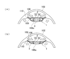
- FIG. 3 is a schematic cross-sectional view for explaining the mechanism of the intraocular lens in the first embodiment.
- FIG. (A) is a figure which shows also a mode that the adjustment power of an intraocular lens is working so that a wearer can be seen near, and (b) is the adjustment power of an intraocular lens so that a wearer can see from a distance. It is a figure which shows a mode that is working.
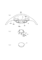
- 6 is a schematic diagram showing an intraocular lens in Embodiment 2.
- FIG. (A) is sectional drawing which shows a mode that the intraocular lens was mounted
- (b) is a perspective view which shows the deformation
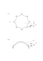
- FIG. 6 is a schematic diagram illustrating a deformation assisting member for an intraocular lens in Embodiment 2.
- FIG. (A) is a plan view, and (b) is a cross-sectional view taken along the line A-A ′.
- FIG. 6 is a schematic cross-sectional view for explaining a method (mechanism) for using an intraocular lens in a second embodiment.
- (A) is a figure which shows a mode that the member for filling in a capsule is inserted in the lens capsule
- (b) is a figure which shows a mode that the deformation
- (c) is a figure which shows a deformation auxiliary member It is a figure which shows a mode that the member for filling in a capsule was swollen in the crystalline lens capsule in which was inserted
- (d) is a figure which shows a mode that focus adjustment is possible with an intraocular lens.
- (c) also shows how the adjustment power of the intraocular lens is working so that the wearer can see from near, and (d) adjusts the intraocular lens so that the wearer can see from far away. It also shows how the force is working.
- Intraocular lens what has a lens function and is arranged inside the lens capsule is referred to as an “intraocular lens”.
- Intraocular lens [Embodiment 1] A) Overall structure of intraocular lens B) Intracapsular filling member C) Deformation assisting member a) Deformation assisting unit [Embodiment 2] A) Overall structure of intraocular lens B) Intracapsular filling member C) Deformation assisting member a) Lens part b) Deformation assisting part Intraocular lens usage (mechanism) 3.
- the intraocular lens according to the present invention is not only worn when the lens is removed by cataract surgery, but also for a wearer who wants to recover the focusing ability to the distant / near distance that has been damaged due to aging etc. Can be applied.
- the inside of the lens capsule is also simply referred to as “inside”.
- the outside of the lens capsule is also simply referred to as “outside”.
- FIG. 1 is a schematic view showing an intraocular lens 1 in the present embodiment.
- (A) And (b) is the schematic which shows the deformation
- (c) is the schematic which shows the member 3 for intracapsular filling in the intraocular lens 1.
- FIG. 1 is a schematic view showing an intraocular lens 1 in the present embodiment.
- (b) is the schematic which shows the deformation
- (c) is the schematic which shows the member 3 for intracapsular filling in the intraocular lens 1.
- FIG. 1 A) Overall Structure of Intraocular Lens
- the intraocular lens 1 in the present embodiment is configured by holding the intracapsular filling member 3 shown in FIG. 1C inside the deformation assisting member 2 shown in FIG. 1A or FIG. 108a (see FIG. 2 (a) or (b)).
- the intracapsular filling member 3 fills the lens capsule 108a and has a predetermined refractive index.
- the deformation assisting member 2 regulates free deformation of the intracapsular filling member 3.
- the intracapsular filling member 3 and the deformation assisting member 2 will be described in detail.
- Intracapsular filling member 3 a gel-like substance that can be deformed by external force is used as the intracapsular filling member 3.
- This gel-like substance has a predetermined refractive index, and the refractive power of the intraocular lens 1 can be adjusted by changing the thickness and the surface shape by deforming the intracapsular filling member 3.
- the refractive index of the gel substance is preferably larger than that of water, for example, about 1.4.
- the intracapsular filling member 3 in the present embodiment has a main surface shape similar to the crystalline lens at least in part.
- the intracapsular filling member 3 when the intracapsular filling member 3 fills the capsule, the intracapsular filling member 3 has a main surface having a shape similar to that of the crystalline lens. If it becomes so, it will become easy to reproduce the shape close
- the intracapsular filling member 3 has a substantially ellipsoidal shape, and the circumference is the longest in the vicinity of the substantially ellipsoidal equator.
- the following effects can be expected by filling the inside of the sac using the capsular filling member 3. That is, if there is a space in the lens capsule 108a, the remaining lens epithelial cells proliferate and transform to form a heterogeneous regenerated lens or produce an extracellular matrix, resulting in a foreign body reaction such as the lens.
- the inside of the sac 108a becomes opaque. However, by filling the sac with the capsular filling member 3, there is no space in the lens capsule 108a, and the above-described opacity does not occur.
- the deformation assisting member 2 includes an annular portion 20, and the deformation assisting portion 22 is formed to protrude from the outer edge of the annular portion 20. More specifically, the deformation assisting portion 22 is a portion extending outward from the annular portion 20 in an open loop shape and an arm shape.
- the deformation assisting portion 22 is smooth from the portion near the boundary between the annular portion 20 and the deformation assisting portion 22 to the distal end portion 22b. And has a contour describing a continuous arc.
- the annular portion 20 and the deformation assisting portion 22 are integrally molded. When the intraocular lens 1 is inserted into the crystalline lens capsule 108a, the inner membrane of the crystalline lens capsule 108a and the deformation assisting portion 22 come into contact with each other.
- the deformation assisting member 2 shown in FIG. 1 (a) the distal end portion 22b of the deformation assisting portion 22 is released. Moreover, in the deformation
- the two annular portions 20a and 20b are arranged coaxially, and the diameters of the openings of the annular portions 20a and 20b may be determined according to the dimensions of the crystalline lens. .
- the annular portion 20 is not particularly limited as long as it is configured so that light from outside the eye enters the intracapsular filling member 3.
- the deformation assisting portion 22 in the present embodiment has a shape that exerts an elastic force (for example, a shape having a spring property, hereinafter also referred to as “spring shape”). That is, the deformation assisting portion 22 is elastically deformed.
- a specific example thereof is a deformation assisting portion 22 having a shape similar to that of a crystalline lens having eight arms as shown in FIG. 1 (a) or (b).
- the deformation assisting portion 22 has such a strength that it is elastically deformed by a force that deforms the lens capsule 108a due to contraction or relaxation of the ciliary body, which will be described later.
- the deformation assisting member 2 holds the intracapsular filling member 3 and regulates free deformation of the intracapsular filling member 3. Therefore, when the ciliary body contracts or relaxes, the intracapsular filling member 3 tries to deform correspondingly, but is restricted by the deformation assisting member 2 and cannot be freely deformed.
- the deformation assisting portion 22 is deformed corresponding to the contraction or relaxation of the ciliary body, and the intracapsular filling member 3 is similarly deformed.
- the deformation assisting portion 22 assists the deformation of the intracapsular filling member 3, and the intracapsular filling member 3 and the deformation assisting member 2 are deformed in cooperation to cope with tension or relaxation of the ciliary body.
- the refractive power of the intracapsular filling member 3 can be adjusted. As a result, focus adjustment as the intraocular lens 1 becomes possible.
- the shape of the deformation assisting portion 22 preferably follows a shape similar to the shape of the crystalline lens during near vision.
- the lens capsule 108a and the deformation assisting portion 22 are formed as shown in FIG. Even if the ciliary zonule is pulled into a flat state, the deformation auxiliaries 22 are brought into a state as shown in FIG. Can be restored.
- the deformation of the capsular bag 108a associated with the distance vision or the near vision in the state where the lens is present is the deformation and the deformation assistance of the intracapsular filling member 3 by the cooperation of the intracapsular filling member 3 and the deformation assisting member 2.
- the deformation assisting portion 22 has a curved shape similar to the shape of the crystalline lens, and the shape of the deformation assisting portion 22 in a state where the deformation assisting portion 22 is not deformed reproduces the shape of the crystalline lens at the near vision. Therefore, the deformation assisting portion 22 can be smoothly restored from the far vision state (FIG. 2B) to the near vision state (FIG. 2A).
- the intracapsular filling member 3 and the deformation can be applied to the tension or relaxation of the ciliary body when the wearer sees far or near.
- Deformation due to the cooperation of the auxiliary portion 22 corresponds, and the refractive power of the intracapsular filling member 3 changes due to this deformation, so that the focus of the intraocular lens 1 can be adjusted.
- the deformation assisting portion 22 holds the vicinity of the equator portion of the intracapsular filling member 3.
- the intracapsular filling member 3 is deformed so as to be flattened from a substantially ellipsoidal shape in response to the tension or relaxation of the ciliary body. Therefore, the deformation assisting portion 22 is the portion having the largest displacement in the intracapsular filling member 3, and the intraocular lens 1 is held by holding the vicinity of the equator corresponding to the connection portion between the ciliary zonule and the lens capsule. Since the lens capsule 108a disposed inside is deformed more smoothly, the refractive power can be adjusted smoothly.
- the intraocular lens 1 according to the present embodiment corresponds to the deformation of the lens capsule 108a when the force (tension / relaxation) acting by the ciliary body is transmitted to the lens capsule 108a, as in the first embodiment. Adjust the focus.
- an intraocular lens 1 in which a lens portion 21 for assisting the refractive power of the intracapsular filling member 3 is provided on the deformation assisting member 2 will be described.
- FIG. 3 is a schematic diagram showing the intraocular lens 1 in the present embodiment.
- (A) is sectional drawing which shows a mode that the intraocular lens 1 was mounted
- (b) is a perspective view which shows the deformation
- (c) is intraocular. It is a perspective view which shows the member 3 for intracapsular filling in the lens 1.
- the intraocular lens 1 in the present embodiment is disposed inside the lens capsule 108a, fills the lens capsule 108a, and has a predetermined refractive index.
- the deformation assisting member 2 in the present embodiment is formed to protrude from the lens portion 21 for assisting the refractive index of the intracapsular filling member 3 and the outer edge of the lens portion 21.
- a deformation assisting portion 22 is integrated. Furthermore, both are integrally molded.
- Intracapsular filling member As in the intracapsular filling member 3, a gel-like substance can be used as in the first embodiment. Moreover, you may swell in a sac using a hydrophilic substance as a gel-like substance. In addition, the intracapsular filling member 3 in FIG. 3C shows a stage before equilibrium swelling. As will be described later in “2. Usage method (mechanism) of intraocular lens”, when a hydrophilic substance is used as the intracapsular filling member 3, first, the intracapsular filling member 3 is inserted into the sac and simultaneously therewith.
- the deformation assisting member 2 inserted after that reproduces the shape in which the intracapsular filling member 3 swells as designed to some extent, and then swells the intracapsular filling member 3.
- the intracapsular filling member 3 absorbs aqueous humor and swells appropriately, and the intracapsular filling member 3 fills the inside of the capsule.
- the intracapsular filling member 3 is a member that fills the inside of the lens capsule 108a.
- the hydrophilic substance described in Patent Document 1 is used.
- a publicly known one may be used.
- An example is a nanocomposite gel (NC gel) having a cross-linking point of a plate-like inorganic viscosity mineral (clay) of several tens of nm dispersed in a solvent.
- the deformation assisting member 2 includes a lens portion 21 and a deformation assisting portion 22, and the deformation assisting portion 22 is formed to protrude from the outer edge of the lens portion 21. That is, the lens portion 21 is provided by replacing the annular portion 20 in the first embodiment. Therefore, the deformation assisting member 2 in the present embodiment may have the same configuration as the deformation assisting member 2 in the first embodiment except that the lens portion 21 is provided. Further, the deformation assisting part 22 plays a role of supporting the lens part 21 in the lens capsule 108a.
- the lens unit 21 in the present embodiment is a part having a lens function that gives a desired optical characteristic (for example, refractive power, addition power, spherical power, astigmatism power, astigmatism, etc.) to the wearer. . More specifically, the lens portion 21 is located at the approximate center of the entire intraocular lens 1 and the shape thereof is a circular or elliptical portion in plan view.
- the lens unit 21 has a predetermined refractive index.
- the refractive index of the lens unit 21 is set according to the refractive index of the intracapsular filling member 3 and assists the refractive index of the intracapsular filling member 3.
- the refractive power of the intraocular lens 1 can be adjusted by the refractive power obtained from the refractive index of the lens unit 21.
- the refractive power of the intracapsular filling member 3 and the refractive power obtained from the refractive index of the lens portion 21 are combined. The refractive power of the intraocular lens 1 can be adjusted.
- the intraocular lens 1 is inserted into the lens capsule 108a, and light from the outside of the eye passes through the intracapsular filling member 3 and the lens unit 21, so that the wearer of the intraocular lens 1
- the desired focal length can be acquired.
- the lens portion 21 is convex with respect to the front (the front surface is convex and the rear surface is concave as shown in FIG. 1 and the like).
- the shape of the lens portion 21 is not particularly limited. That is, as long as the intraocular lens 1 is combined with the intracapsular filling member 3, it may be a convex lens, a concave lens, or a prism.
- the lens unit 21 is made of a soft material that allows the lens unit 21 to be folded.
- the term “foldable” described here is used to mean that the intraocular lens 1 including the lens portion 21 can be folded in at least two. Therefore, the soft material constituting the lens portion 21 may be a material having a high flexibility enough to fold the lens portion 21.
- soft acrylic is used for the lens unit 21.
- soft materials such as silicone resin, acrylic resin, hydrogel, and urethane resin can be used.
- the present invention may be applied to the intraocular lens 1 that does not require folding.
- PP polypropylene
- polyimide polyimide
- PMMA polymethyl methacrylate
- a known material may be used as long as it can be used as the lens portion 21.
- the deformation assisting portion 22 is configured in the same manner as in the first embodiment. Therefore, as in the first embodiment, the intracapsular filling member 3 and the deformation assisting portion 22 are deformed in cooperation with the tension or relaxation of the ciliary body, so that the refractive power of the intracapsular filling member 3 is increased. Changes. Furthermore, in this embodiment, since the deformation
- the displacement of the lens unit 21 assists the focus adjustment due to the deformation of the intracapsular filling member 3, and the focus adjustment as the intraocular lens 1 is realized.
- focus adjustment as the intraocular lens 1 is realized by the displacement of the lens unit 21.
- FIG. 5 is used to describe the usage method and mechanism of the intraocular lens 1 in the second embodiment.
- the present method and mechanism can also be applied to the intraocular lens 1 in the first embodiment. it can.
- FIG. 5A is a diagram showing a state in which the intracapsular filling member 3 is inserted into the lens capsule 108a before the equilibrium swelling
- FIG. 5B is a diagram illustrating the deformation assisting member 2 in the lens capsule 108a.
- FIG. 5C is a view showing a state in which the intracapsular filling member 3 is swollen in the lens capsule 108a in which the deformation assisting member 2 is inserted
- FIG. These are figures which show a mode that focus adjustment is possible with the intraocular lens 1.
- FIG. In addition, (c) also shows how the adjustment power of the intraocular lens is working so that the wearer can see from near, and (d) adjusts the intraocular lens so that the wearer can see from far away. It also shows how the force is working.
- a known method may be used for extracting the lens from the lens capsule 108a.
- a small opening of about 6 mm (CCC: Continuous Curvilleline Capsular Hexis or Continuous Circular Capsule hexis) is formed in the anterior capsule of the lens capsule 108a, and ultrasonic emulsification (PEA) is used.
- CCC Continuous Curvilleline Capsular Hexis or Continuous Circular Capsule hexis
- the intracapsular filling member 3 is prepared in advance.
- This intracapsular filling member 3 is an NC gel that has the property of being swellable by the body fluid of the wearer, and the shape after swelling is designed to be similar to the shape of the crystalline lens. Then, this intracapsular filling member 3 is inserted into the injector.
- the injector may be a known surgical instrument used to insert the intraocular lens 1 into the eye.
- the injector is used to insert the intracapsular filling member 3 and the deformation assisting member 2 into the eye.
- the distal end portion of the injector to which the intracapsular filling member 3 is attached is inserted into the opening on the eye surface, and is further brought into the hole of the crystalline lens capsule 108a, and the intracapsular filling member 3 is pushed out from the injector in this state.
- the intracapsular filling member 3 is inserted into the lens capsule 108a through the opening.
- the deformation assisting member 2 is folded in advance.
- the deformation assisting member 2 may be folded in any way.
- the deformation assisting member 2 can be folded in a manner that the lens portion 21 is folded in half so that the eight deformation assisting portions 22 do not overlap each other ( At that time, the eight deformation assisting portions 22 are folded at the base portion 22a and the folded deformation assisting portion 22 is wrapped by the lens portion 21).
- This is inserted into the injector, the tip of the injector to which the intraocular lens 1 is attached is inserted into the opening on the surface of the eye, and is made to face the hole in the crystalline lens capsule 108a, and in this state, the deformation assisting member 2 is pushed out from the injector. Then, the deformation assisting member 2 is inserted into the eye (the lens capsule 108a) through the opening.
- the deformation assisting member 2 in a folded state is developed into an original shape using a lever or the like.
- shape deformation property may be imparted to the deformation assisting member 2.
- the deformation assisting member 2 can be naturally deployed without using a lever or the like, and the burden on the operator can be reduced.
- the deformation assisting member 2 and the lens capsule 108a become familiar.
- the shape of the intracapsular filling member 3 when swollen as designed can be reproduced to some extent by the deformation assisting member 2.
- the deformation assisting member 2 and the intracapsular filling member 3 are arranged so as to be half-enclosed by the deformation assisting member 2.
- the intracapsular filling member 3 gradually absorbs body fluid (aqueous humor) and swells, and the space in the lens capsule 108a is filled with the intracapsular filling member 3. That is, the body fluid of the wearer is used as part of the configuration of the intraocular lens 1, and the intracapsular filling member 3 is swollen. By doing so, abnormal proliferation of residual cells and foreign body reaction in the body can be suppressed extremely effectively, and the physical burden on the wearer can be reduced.
- body fluid aqueous humor
- the ciliary body contracts or relaxes when the wearer tries to apply the adjusting force of the intraocular lens 1 so that the wearer can see far or near.
- the intracapsular filling member 3 and the deformation assisting portion 22 can be deformed in cooperation with each other.
- the ciliary body 110 relaxes, the chin band 109 contracts, and the capsular bag 108a attempts to deform flatly, the deformation assisting portion 22 is light-transmitted. Try to elastically deform in the axial direction.
- the intracapsular filling member 3 since deformation of the intracapsular filling member 3 is regulated by the deformation assisting portion 22, the intracapsular filling member 3 cannot be freely deformed, and the intracapsular filling member 3 is also deformed flat according to the deformation of the deformation assisting portion 22. To do. As a result, the focal length of the intracapsular filling member 3 is extended, and the focus adjustment during far vision is smoothly performed.
- the ciliary body 110 contracts as shown in FIG. 5C
- the chin band 109 relaxes, and the lens capsule 108a deforms into a substantially spherical shape
- the elastic force applied to the deformation assisting portion 22 is released
- An attempt is made to restore the original shape (for example, the shape of the crystalline lens during near vision) while restricting deformation of the intracapsular filling member 3.
- all of the elastic force applied to the deformation assisting portion 22 is released, the shape in a state where the deformation assisting portion 22 is not deformed is reproduced, and the shape of the crystalline lens capsule 108a is also reproduced in near vision. It will be.
- the intracapsular filling member 3 is also deformed into a substantially spherical shape with the deformation of the deformation assisting portion 22.
- the focal length of the intracapsular filling member 3 is shortened, and the focus adjustment during near vision is smoothly performed.
- the opening formed in the lens capsule 108a may be closed by a known method after the operation.
- the front surface (that is, the front surface) of the lens portion 21 is disposed so as to oppose the opening, and the diameter of the lens portion 21 is preferably larger than the diameter of the opening.
- the force generated by the deformation of the intracapsular filling member 3 is transmitted to the lens portion 21, so that the lens portion 21 is moved into the lens capsule 108 a.
- the lid of the opening With this configuration, the opening of the lens capsule 108a can be efficiently blocked, and the possibility that the intracapsular filling member 3 escapes from the opening can be reduced.
- the intracapsular filling member 3 having a predetermined refractive index is held by the deformation assisting member 2, and the intracapsular filling member 3 cannot be freely deformed. Therefore, the deformation of the intracapsular filling member 3 is regulated by the deformation assisting portion 22 of the deformation assisting member 2. Further, when the deformation assisting portion 22 is elastically deformed by an external force, the intracapsular filling member 3 is similarly deformed according to the deformation of the deformation assisting member 22, so that the intracapsular filling member 3 and the deformation assisting member 2 cooperate. It becomes possible to deform together.
- the deformation assisting portion 22 is deformed in response to the tension or relaxation of the ciliary body when the wearer views far or near, the intracapsular filling member 3 is similarly deformed, and the intraocular lens 1 Therefore, the focus adjustment as the intraocular lens 1 becomes possible.
- the deformation assisting member 22 when the deformation assisting member 22 is not deformed, the deformation assisting member 22 has a shape for near vision, so that the deformation of the lens capsule 108a from far vision to near vision becomes smoother, It is easier to adjust the focus of the intraocular lens.
- the intracapsular filling member 3 can be adjusted to the extent that desired focus adjustment is possible. It is difficult to control the deformation.
- the deformation assisting member 22 has the above-described configuration, so that the deformation assisting member 22 can regulate the deformation of the intracapsular filling member 3.
- the deformation assisting member 22 when the deformation assisting member 22 is deformed so as to correspond to the tension or relaxation of the ciliary body, the deformation assisting member 22 is in the same extent as the deformation assisting member 22 regardless of the mechanical characteristics (such as elastic modulus) of the intracapsular filling member 3. Since the filling member 3 is deformed, desired focus adjustment is possible. That is, the above effect can be obtained even if the substance is designed by paying attention to the refractive index of the intracapsular filling member 3 without considering the mechanical characteristics of the intracapsular filling member 3. The degree of freedom increases.
- the lens portion 21 is deformed by deformation of the deformation assisting member 2 when the refractive power of the intracapsular filling member 3 cannot be obtained. Is displaced in the direction of the optical axis, and the focal length changes. As a result, focus adjustment as the intraocular lens 1 can be realized. Further, when the refractive power of the intracapsular filling member 3 can be obtained to some extent, the displacement of the lens portion 21 assists this refractive power, and the focus adjustment as the intraocular lens 1 can be realized.
- the intracapsular filling member 3 can fill the lens capsule 108a without any gap.
- the deformation assisting member 2 is configured to reproduce the shape in which the intracapsular filling member 3 swells as designed to some extent from the stage before the intracapsular filling member 3 swells. Therefore, when the intracapsular filling member 3 absorbs the body fluid (aqueous humor) of the wearer and swells, the intracapsular filling member 3 swells in the designed shape and can fill the crystalline lens capsule 108a without a gap.
- the focus adjustment corresponding to the deformation of the lens capsule 108a can be easily performed for a long period of time.
- the present invention is not limited to the contents of the above-described embodiment, and can be appropriately changed without departing from the gist thereof.
- the parts such as the deformation assisting member 2 and the intracapsular filling member 3 mentioned in the above embodiment may be integrated structurally only if the material of each part is different if the focus can be adjusted. It can be good or separate. However, in the manufacturing process of the intraocular lens 1, it is efficient to integrally mold it, and that is preferable.
- the deformation assisting portion 22 includes a root portion 22a that is a portion near the boundary between the annular portion 20 or the lens portion 21 and the deformation assisting portion 22, and other portions of the deformation assisting portion 22 (that is, most viewed from the center). And a distal end portion 22b which is an outer portion (the distal end portion of the deformation assisting portion 22).
- FIG. 4 is a schematic diagram showing the deformation assisting member 2 of the intraocular lens 1 in the second embodiment.
- (A) is a plan view
- (b) is a cross-sectional view taken along the line AA ′.
- the base portion 22a of the deformation assisting portion 22 is formed to be wide at the foot of the mountain toward the geometric center of the lens portion 21 when viewed in plan, and the lens portion 21 at the widest portion. Connected to. In this way, in addition to the case where the entire deformation assisting portion 22 is formed of a hard material described later, the load concentrates on the boundary portion between the lens portion 21 and the deformation assisting portion 22 and the deformation assisting member 2 is damaged. It is possible to suppress the risk of being lost.
- the shape of the deformation assisting portion 22 with respect to the above-mentioned root portion 22a (that is, the shape combining the root portion 22a and the tip portion 22b) is initially removed from the root portion 22a as shown in FIG. In the direction toward the outside, it extends slenderly outwardly, and then extends while being further inclined downward in the vertical direction. At this time, the cross-sectional shape of the deformation assisting portion 22 may extend outwardly from the center of the lens portion 21 while curving in a shape following the crystalline lens shape.
- the lens portion 21 and the deformation assisting portion 22 may have a continuous shape on the front and rear surfaces when viewed in cross-section, and are bent at an intermediate portion of the deformation assisting portion 22. You may have a shape.
- assistant part 22 may bend in the shape which followed the shape of a sac initially, and may extend substantially perpendicular
- the cross-sectional view shape and the most advanced portion of the distal end portion 22b are rounded so as not to damage the lens capsule 108a even if it contacts the lens capsule 108a.
- the cross-sectional view shape of the base portion 22a may be rounded.
- the deformation assisting portion 22 in the first and second embodiments is made of a material having a hardness different from that of the annular portion 20 or the lens portion 21.
- the material is not limited in embodying the idea of the present invention.
- the deformation assisting part 22 (at least the base part 22a) is made of a hard material. It is preferable for stable arrangement. If a specific example is given as a material for the deformation assisting portion 22 other than PMMA, a hard material such as polypropylene or polyamide can be used.
- assistant part 22 whole may be comprised with the same material
- tip part 22b and the base part 22a may each be comprised with a different material
- those combinations may be comprised with the same material. good.
- the base portion 22a is made of a mixture of a hard material and a soft material so as to have a certain strength and flexibility. It may be used as
- the hard material content ratio may be changed (for example, decreased) from the lens portion 21 side to the distal end side of the base portion 22a, and the hard material content ratio may be changed in the thickness direction of the deformation assisting portion 22. It may be changed (for example, decreased). By doing so, the flexibility of the base portion 22a on the lens portion 21 side is further increased, and damage during folding can be further suppressed.
- tip part 22b there is no restriction
- Either a soft material or a hard material constituting the lens portion 21 and the base portion 22a can be used, but when the distal end portion 22b is made of a hard material, the shape of the lens capsule after the lens is removed is more firmly Will be able to maintain.
- Specific examples of the constituent material of the tip 22b include one or more selected from polypropylene (PP), polymethyl methacrylate (PMMA), fluororesin (polyvinylidene fluoride), polyimide resin, and the like. In the first and second embodiments, PMMA is used for the tip 22b.
- the base portion 22a has the above shape, and the same material as the lens portion 21 (that is, soft acrylic) is used as the material.
- the tip portion 22b has the above-mentioned shape, and PMMA is used as a material.
- the intraocular lens 1 is folded, when the intraocular lens 1 is returned to the original shape again in the lens capsule 108a, a difference in hardness between the distal end portion 22b and the lens portion 21 is given (depending on the case, the adhesive strength may be increased). Therefore, the folded state of the intraocular lens 1 can be easily released because the distal end portion 22b tries to return to the original shape earlier than the lens portion 21.
- the deformation assisting portions 22 in the first and second embodiments are formed in an open loop shape and an outwardly extending arm shape, and eight of them are formed at equal intervals on the outer edge of the lens portion 21.
- the deformation assisting portion 22 applied to the present invention may have other shapes.
- the deformation assisting portion 22 is not in an open loop shape but in a closed loop shape, the deformation assisting portion 22 is not in an arm shape but is in a flat plate or curved plate shape, or not in number of 7 or less, or 9
- the deformation assisting part 22 may be as described above.
- the arm shape is preferable because the deformation assisting portion 22 can exhibit the elastic force described above.
- the deformation assisting portion 22 preferably has a shape similar to the crystalline lens at least in part, but this need not be the case. That is, even if the deformation assisting portion 22 does not have a shape similar to the crystalline lens, the lens capsule 108a may be supported by the deformation assisting portion 22 at a predetermined portion inside the lens capsule 108a as if a tent is stretched. Absent.
- the diameter of the lens unit 21 in the second embodiment may be set to any size as long as the size is suitable for inserting the intraocular lens 1 into the lens capsule 108a in the eye.
- the diameter D of the lens portion 21 is preferably set in a range of 5 mm to 7 mm, more preferably 6 mm. What is necessary is just to set the thickness of the lens part 21 according to a desired refractive index.
- the lens unit 21 to which the intraocular lens 1 is attached is arranged to serve as a lid for the opening.
Landscapes
- Health & Medical Sciences (AREA)
- Ophthalmology & Optometry (AREA)
- Cardiology (AREA)
- Oral & Maxillofacial Surgery (AREA)
- Transplantation (AREA)
- Engineering & Computer Science (AREA)
- Biomedical Technology (AREA)
- Heart & Thoracic Surgery (AREA)
- Vascular Medicine (AREA)
- Life Sciences & Earth Sciences (AREA)
- Animal Behavior & Ethology (AREA)
- General Health & Medical Sciences (AREA)
- Public Health (AREA)
- Veterinary Medicine (AREA)
- Prostheses (AREA)
Priority Applications (1)
| Application Number | Priority Date | Filing Date | Title |
|---|---|---|---|
| JP2014521422A JP6140155B2 (ja) | 2012-06-14 | 2013-06-14 | 眼内レンズ |
Applications Claiming Priority (2)
| Application Number | Priority Date | Filing Date | Title |
|---|---|---|---|
| JP2012135221 | 2012-06-14 | ||
| JP2012-135221 | 2012-06-14 |
Publications (1)
| Publication Number | Publication Date |
|---|---|
| WO2013187497A1 true WO2013187497A1 (fr) | 2013-12-19 |
Family
ID=49758315
Family Applications (1)
| Application Number | Title | Priority Date | Filing Date |
|---|---|---|---|
| PCT/JP2013/066434 Ceased WO2013187497A1 (fr) | 2012-06-14 | 2013-06-14 | Lentille intraoculaire |
Country Status (2)
| Country | Link |
|---|---|
| JP (1) | JP6140155B2 (fr) |
| WO (1) | WO2013187497A1 (fr) |
Cited By (2)
| Publication number | Priority date | Publication date | Assignee | Title |
|---|---|---|---|---|
| JP2016168205A (ja) * | 2015-03-13 | 2016-09-23 | 株式会社トプコン | 眼機能補助装置 |
| WO2017109624A1 (fr) * | 2015-12-22 | 2017-06-29 | Novartis Ag | Lentille intraoculaire d'accommodation |
Citations (4)
| Publication number | Priority date | Publication date | Assignee | Title |
|---|---|---|---|---|
| JP2003527898A (ja) * | 1999-09-10 | 2003-09-24 | ランドル ウッズ | 眼の調節能力を有する眼内レンズ |
| JP2006516002A (ja) * | 2002-10-25 | 2006-06-15 | クエスト ヴィジョン テクノロジー, アイエヌシー. | 内部に屈折性液体を有するカプセル型埋込人工水晶体 |
| JP2006305070A (ja) * | 2005-04-28 | 2006-11-09 | Nidek Co Ltd | 眼内レンズ |
| US20120116506A1 (en) * | 2010-11-09 | 2012-05-10 | Compertore David C | Accommodating intraocular lens system including a bag |
-
2013
- 2013-06-14 WO PCT/JP2013/066434 patent/WO2013187497A1/fr not_active Ceased
- 2013-06-14 JP JP2014521422A patent/JP6140155B2/ja active Active
Patent Citations (4)
| Publication number | Priority date | Publication date | Assignee | Title |
|---|---|---|---|---|
| JP2003527898A (ja) * | 1999-09-10 | 2003-09-24 | ランドル ウッズ | 眼の調節能力を有する眼内レンズ |
| JP2006516002A (ja) * | 2002-10-25 | 2006-06-15 | クエスト ヴィジョン テクノロジー, アイエヌシー. | 内部に屈折性液体を有するカプセル型埋込人工水晶体 |
| JP2006305070A (ja) * | 2005-04-28 | 2006-11-09 | Nidek Co Ltd | 眼内レンズ |
| US20120116506A1 (en) * | 2010-11-09 | 2012-05-10 | Compertore David C | Accommodating intraocular lens system including a bag |
Cited By (5)
| Publication number | Priority date | Publication date | Assignee | Title |
|---|---|---|---|---|
| JP2016168205A (ja) * | 2015-03-13 | 2016-09-23 | 株式会社トプコン | 眼機能補助装置 |
| WO2017109624A1 (fr) * | 2015-12-22 | 2017-06-29 | Novartis Ag | Lentille intraoculaire d'accommodation |
| US10004595B2 (en) | 2015-12-22 | 2018-06-26 | Novartis Ag | Accommodating intraocular lens |
| CN108430389A (zh) * | 2015-12-22 | 2018-08-21 | 诺华股份有限公司 | 调节性人工晶状体 |
| JP2018538060A (ja) * | 2015-12-22 | 2018-12-27 | ノバルティス アーゲー | 遠近調節型眼内レンズ |
Also Published As
| Publication number | Publication date |
|---|---|
| JP6140155B2 (ja) | 2017-05-31 |
| JPWO2013187497A1 (ja) | 2016-02-08 |
Similar Documents
| Publication | Publication Date | Title |
|---|---|---|
| JP6859409B2 (ja) | 遠近調節型の眼内レンズ | |
| JP6564031B2 (ja) | 調節性曲率変化眼内レンズ | |
| CN102271623B (zh) | 眼内晶状体以及补偿囊体尺寸变化和后植入眼内改变的方法 | |
| JP4933898B2 (ja) | 後方の湾曲可能な光学体を備えた眼内レンズ移植物 | |
| US8070806B2 (en) | Accommodative intra-ocular lens | |
| US5275623A (en) | Elliptical accommodative intraocular lens for small incision surgery | |
| EP3305250B1 (fr) | Ensemble de lentille intraoculaire | |
| US20050107873A1 (en) | Accommodative intraocular lens and method of implantation | |
| US20160235523A1 (en) | Curvature-changing, accommodative intraocular lenses with expandable peripheral reservoirs | |
| TW201632151A (zh) | 雙鏡片、曲率變化調節式iol | |
| KR20040105813A (ko) | 직조된 햅틱부를 갖는 조절기능성 안내 렌즈 | |
| JP2005511201A (ja) | 調節型眼内レンズ | |
| JP2010527261A (ja) | 溝用トーリックレンズ | |
| MX2011005311A (es) | Lente intraocular artificial, lente cristalino natural alterado, o capsula de lente cristalino natural relleno con una o mas protesis esclerales para funcionamiento mejorado. | |
| JP2006516002A (ja) | 内部に屈折性液体を有するカプセル型埋込人工水晶体 | |
| KR101718074B1 (ko) | 안구내렌즈 지지체 | |
| JP6140155B2 (ja) | 眼内レンズ |
Legal Events
| Date | Code | Title | Description |
|---|---|---|---|
| 121 | Ep: the epo has been informed by wipo that ep was designated in this application |
Ref document number: 13805043 Country of ref document: EP Kind code of ref document: A1 |
|
| ENP | Entry into the national phase |
Ref document number: 2014521422 Country of ref document: JP Kind code of ref document: A |
|
| NENP | Non-entry into the national phase |
Ref country code: DE |
|
| 122 | Ep: pct application non-entry in european phase |
Ref document number: 13805043 Country of ref document: EP Kind code of ref document: A1 |