WO2013190761A1 - Machine de massage à l'air - Google Patents
Machine de massage à l'air Download PDFInfo
- Publication number
- WO2013190761A1 WO2013190761A1 PCT/JP2013/002883 JP2013002883W WO2013190761A1 WO 2013190761 A1 WO2013190761 A1 WO 2013190761A1 JP 2013002883 W JP2013002883 W JP 2013002883W WO 2013190761 A1 WO2013190761 A1 WO 2013190761A1
- Authority
- WO
- WIPO (PCT)
- Prior art keywords
- airbag
- armrest
- stimulation
- air
- row
- Prior art date
- Legal status (The legal status is an assumption and is not a legal conclusion. Google has not performed a legal analysis and makes no representation as to the accuracy of the status listed.)
- Ceased
Links
Images







Classifications
-
- A—HUMAN NECESSITIES
- A61—MEDICAL OR VETERINARY SCIENCE; HYGIENE
- A61H—PHYSICAL THERAPY APPARATUS, e.g. DEVICES FOR LOCATING OR STIMULATING REFLEX POINTS IN THE BODY; ARTIFICIAL RESPIRATION; MASSAGE; BATHING DEVICES FOR SPECIAL THERAPEUTIC OR HYGIENIC PURPOSES OR SPECIFIC PARTS OF THE BODY
- A61H9/00—Pneumatic or hydraulic massage
- A61H9/005—Pneumatic massage
- A61H9/0078—Pneumatic massage with intermittent or alternately inflated bladders or cuffs
-
- A—HUMAN NECESSITIES
- A61—MEDICAL OR VETERINARY SCIENCE; HYGIENE
- A61H—PHYSICAL THERAPY APPARATUS, e.g. DEVICES FOR LOCATING OR STIMULATING REFLEX POINTS IN THE BODY; ARTIFICIAL RESPIRATION; MASSAGE; BATHING DEVICES FOR SPECIAL THERAPEUTIC OR HYGIENIC PURPOSES OR SPECIFIC PARTS OF THE BODY
- A61H2201/00—Characteristics of apparatus not provided for in the preceding codes
- A61H2201/01—Constructive details
- A61H2201/0119—Support for the device
- A61H2201/0138—Support for the device incorporated in furniture
- A61H2201/0149—Seat or chair
-
- A—HUMAN NECESSITIES
- A61—MEDICAL OR VETERINARY SCIENCE; HYGIENE
- A61H—PHYSICAL THERAPY APPARATUS, e.g. DEVICES FOR LOCATING OR STIMULATING REFLEX POINTS IN THE BODY; ARTIFICIAL RESPIRATION; MASSAGE; BATHING DEVICES FOR SPECIAL THERAPEUTIC OR HYGIENIC PURPOSES OR SPECIFIC PARTS OF THE BODY
- A61H2201/00—Characteristics of apparatus not provided for in the preceding codes
- A61H2201/16—Physical interface with patient
- A61H2201/1602—Physical interface with patient kind of interface, e.g. head rest, knee support or lumbar support
- A61H2201/1635—Hand or arm, e.g. handle
- A61H2201/1638—Holding means therefor
-
- A—HUMAN NECESSITIES
- A61—MEDICAL OR VETERINARY SCIENCE; HYGIENE
- A61H—PHYSICAL THERAPY APPARATUS, e.g. DEVICES FOR LOCATING OR STIMULATING REFLEX POINTS IN THE BODY; ARTIFICIAL RESPIRATION; MASSAGE; BATHING DEVICES FOR SPECIAL THERAPEUTIC OR HYGIENIC PURPOSES OR SPECIFIC PARTS OF THE BODY
- A61H2205/00—Devices for specific parts of the body
- A61H2205/06—Arms
Definitions
- the present invention relates to an air massage machine including an air bag and an armrest.
- an air massage machine including an armrest having a first armrest portion and a second armrest portion facing the first armrest portion with an arm arrangement space in between is known (for example, Patent Document 1).
- an air bag is disposed on at least one of the first armrest portion and the second armrest portion.
- the conventional air massage machine can only perform a monotonous massage in which an air bag presses the arm.
- An object of the present invention is to provide an air massage machine that can apply various stimuli to the arm.
- the air massage machine includes an armrest including a first armrest portion and a second armrest portion facing the first armrest portion with an arm placement space for placing an arm therebetween.
- An air massage machine is provided with the 1st air bag arrange
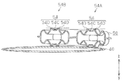
- the second airbag includes a stimulation part row including a plurality of stimulation parts arranged along a longitudinal direction of the armrest, and the plurality of stimulation parts can protrude toward the second armrest part. It is configured as follows.
- the stimulation unit row is one of a plurality of stimulation unit rows in the second airbag.
- the second airbag includes an outer peripheral portion provided around the stimulation portion row, and the plurality of stimulation portions are more than the outer peripheral portion when the second airbag is inflated most.
- the plurality of stimulating portions are located closer to the first armrest portion than the outer peripheral portion when the second airbag is most contracted, or the second stimulation portion is located close to the second armrest portion, or It is preferable to be located at a position separated from one armrest portion by the same distance as the outer peripheral portion.
- each of the plurality of stimulation units includes a first stimulation unit and a second stimulation unit
- the first airbag has two portions that are inflated with different expansion amounts toward the second armrest unit.
- the first stimulation unit and the second stimulation unit are respectively overlapped with two portions of the first airbag that are inflated with different expansion amounts toward the second armrest portion.
- the air massage machine includes a seat portion, the plurality of stimulation unit rows include a first stimulation unit row and a second stimulation unit row, and the first stimulation unit row includes the second stimulation unit.
- the armrests are arranged closer to the seat than the row, and the base end of the armrest is located closer to the seat than the tip of the armrest.
- the present invention provides an air massage machine that can apply various stimuli to the arm.
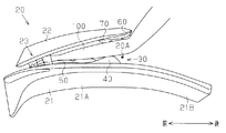
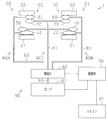
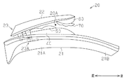
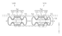
- FIG. 1 It is a perspective view of the air massage machine of an embodiment, and a perspective view showing the whole structure of an air massage machine. It is a front view of the armrest of an embodiment, and a front view showing the front structure of an armrest when an arm is arranged between the 1st armrest part and the 2nd armrest part. It is a schematic diagram of the air massage machine of embodiment, and is a schematic diagram which shows the relationship between each airbag and a supply system. It is a front view of the 1st armrest part of an embodiment, and is a front view showing the front structure of the 1st armrest part. It is a front view of the 2nd air bag of an embodiment, and a front view showing the front structure of the 2nd air bag. FIG.
- FIG. 6 is a cross-sectional view of the second airbag according to the embodiment, showing a cross-sectional structure taken along line Z6-Z6 of FIG. It is a front view of the 2nd armrest part of an embodiment, and a front view showing the front structure of the 2nd armrest part. It is a front view of the armrest of an embodiment, and a front view showing the front structure of an armrest when the 2nd armrest part is closest to the 1st armrest part. It is a front view of the armrest of an embodiment, and a front view showing the front structure of an armrest when the 2nd armrest part is the furthest away from the 1st armrest part.
- the air massage machine 1 is configured as a chair type massage machine.
- the air massage machine 1 has a main body 10, a supply device 80 (see FIG. 3), a control device 90 (see FIG. 3), and a remote controller 91.
- the main body 10 includes a seat portion 11 having a seating surface 11A, a backrest 12, an ottoman 13, and two armrests 20.
- the supply device 80 (see FIG. 3) and the control device 90 (see FIG. 3) are disposed inside the main body 10.
- the remote controller 91 is disposed at the right end of the main body 10.
- the massage machine 1 starts and ends massage by the operation of the user's remote control.
- the two armrests 20 have a right armrest 20 for placing the user's right arm 100 and a left armrest 20 for placing the user's left arm 100.
- the right armrest 20 is disposed adjacent to the right end of the seat 11 and the backrest 12.
- the left armrest 20 is disposed adjacent to the left end of the seat 11 and the backrest 12.
- the right armrest 20 and the left armrest 20 have symmetrical shapes.
- each armrest 20 has a first armrest portion 21, a second armrest portion 22, a rotation mechanism 23, and an airbag group 30.
- An arm placement space 20 ⁇ / b> A is formed between the first armrest portion 21 and the second armrest portion 22.
- the first armrest portion 21 has a forearm arrangement portion 21A provided at the distal end of the first armrest portion 21 and a main body fixing portion 21B provided at the base end of the first armrest portion 21.
- the forearm placement portion 21A has a length that allows the portion from the elbow to the fingertip of the user's arm 100 to be placed.
- the first armrest portion 21 is fixed to the seat portion 11.
- the second armrest portion 22 is provided above the first armrest portion 21.
- the second armrest portion 22 faces the forearm arrangement portion 21 ⁇ / b> A of the first armrest portion 21.
- a proximal end of the second armrest portion 22 is rotatably attached to the first armrest portion 21 via a rotation mechanism 23.
- the airbag group 30 is disposed between the first armrest portion 21 and the second armrest portion 22.
- the airbag group 30 includes a first airbag 40, a second airbag 50, a third airbag 60, and a fourth airbag 70.
- the first airbag 40, the second airbag 50, the third airbag 60, and the fourth airbag 70 are formed by, for example, blow molding.
- the first airbag 40 and the second airbag 50 are disposed on the upper surface of the first armrest portion 21.
- the third airbag 60 and the fourth airbag 70 are disposed on the lower surface of the second armrest portion 22.
- the first armrest portion 21 has a cloth-like cover (not shown) that covers the first airbag 40 and the second airbag 50.
- the second armrest portion 22 has a cloth-like cover (not shown) that covers the third airbag 60 and the fourth airbag 70.
- the supply device 80 includes a pump 81, a solenoid valve 82, and three tubes 83.
- the pump 81 is connected to two groups of airbags 30 through three tubes 83 and a solenoid valve 82. Air from the pump 81 is supplied to the two airbag groups 30 via the three tubes 83 and the electromagnetic valve 82.
- the first air bag 40 on the right side, the third air bag 60 on the right side, and the electromagnetic valve 82 are connected via a first supply system 80A.
- the left side first air bag 40 and the left side third air bag 60 are connected to the electromagnetic valve 82 via the second supply system 80B.
- the second airbag 50 on the right side, the fourth airbag 70 on the right side, the second airbag 50 on the left side, the fourth airbag 70 on the left side, and the solenoid valve 82 are connected via a third supply system 80C.
- the pump 81 is driven and stopped according to a control signal from the control device 90.
- the electromagnetic valve 82 supplies and discharges air in the first supply system 80A, the second supply system 80B, and the third supply system 80C based on a control signal from the control device 90.
- the supply device 80 supplies and discharges air in each of the supply systems 80A to 80C by a combination of the following (state A) to (state F) according to switching of the electromagnetic valve 82.
- (State A) The first supply system 80A and the pump 81 are connected, the second supply system 80B is opened to the atmosphere, and the third supply system 80C is opened to the atmosphere.
- (State B) The first supply system 80A and the pump 81 are connected, the second supply system 80B is opened to the atmosphere, and the third supply system 80C and the pump 81 are connected.
- State C The first supply system 80A is opened to the atmosphere, the second supply system 80B and the pump 81 are connected, and the third supply system 80C is opened to the atmosphere.
- (State D) The first supply system 80A is opened to the atmosphere, the second supply system 80B and the pump 81 are connected, and the third supply system 80C and the pump 81 are connected.
- (State E) The first supply system 80A is opened to the atmosphere, the second supply system 80B is opened to the atmosphere, and the third supply system 80C is opened to the atmosphere.
- (State F) The first supply system 80A is opened to the atmosphere, the second supply system 80B is opened to the atmosphere, and the third supply system 80C and the pump 81 are connected.
- the first airbag 40 covers almost the entire upper surface of the forearm arrangement portion 21 ⁇ / b> A of the first armrest portion 21.
- the first airbag 40 has a flat surface.
- a supply port 43 for connecting to the tube 83 is provided at the front end 41 of the first airbag 40.
- a front end 41 of the first airbag 40 is fixed to the first armrest portion 21.
- the second airbag 50 is arranged so as to be biased toward the tip of the first armrest portion 21.
- the second airbag 50 has an uneven surface.
- a supply port 53 for connecting to the tube 83 is provided at the front end 51 of the second airbag 50.
- a front end 51 of the second airbag 50 is fixed to the first armrest portion 21 and the first airbag 40.
- the second airbag 50 is stacked on the upper surface of the first airbag 40.
- the second airbag 50 is smaller than the first airbag 40.
- the front end 51 of the second airbag 50 is disposed in alignment with the front end 41 of the first airbag 40. Accordingly, the rear end 42 of the first airbag 40 protrudes beyond the rear end 52 of the second airbag 50.
- the second airbag 50 divides the twelve stimulation parts 54 protruding toward the second armrest part 22 and the twelve stimulation parts 54 into three stimulation parts 54. And four outer peripheral portions 55 respectively formed around the four stimulation regions formed by the above.
- first stimulation unit row 54A six of the twelve stimulation units 54 are arranged along the longitudinal direction of the armrest 20 to form a first stimulation unit row 54A.
- the remaining six stimulation parts 54 are arranged along the longitudinal direction of the armrest 20 adjacent to the first stimulation part row 54A to form the second stimulation part row 54B.
- the first stimulation part row 54A is formed closer to the seat part 11 than the second stimulation part row 54B.
- the rear end is located closer to the seat part 11 than the front end.
- Each stimulation part 54 has a side along the longitudinal direction that is longer than a side along the width direction of the armrest 20.
- the four outer peripheral portions 55 are arranged around the three stimulation portions 54 on the front end 51 side of the first stimulation portion row 54A, around the three stimulation portions 54 on the rear end 52 side of the first stimulation portion row 54A, and the second It is formed so as to surround the three stimulation parts 54 on the front end 51 side of the stimulation part row 54B and the three stimulation parts 54 on the rear end 52 side of the first stimulation part row 54A.
- Each outer peripheral portion 55 has a side along the longitudinal direction of the armrest 20 that is longer than the side along the width direction of the armrest 20.
- FIG. 6 shows a cross-sectional structure of the second airbag 50 when air to the second airbag 50 is blocked and no external pressure is applied to the second airbag 50.
- Each stimulator 54 has a central portion 54C and a protrusion 54D surrounding the central portion 54C.
- the central portion 54C of the stimulation portion 54 protrudes toward the second armrest portion 22 from the outer peripheral portion 55, that is, upward.
- the protruding portion 54D protrudes upward from the central portion 54C.
- the third airbag 60 is disposed so as to be biased toward the tip of the second armrest portion 22.
- the third airbag 60 has a flat surface.
- a supply port 63 for connecting to the tube 83 is provided at the front end 61 of the third airbag 60.
- a front end 61 of the third airbag 60 is fixed to the second armrest portion 22.
- the fourth airbag 70 is arranged so as to be biased toward the tip of the second armrest portion 22.
- the fourth airbag 70 has three air chambers 70 ⁇ / b> A arranged from the front end 61 toward the rear end 62.
- a supply port 63 for connecting to the tube 83 is provided at the front end 71 of the fourth airbag 70.
- a front end 71 of the fourth airbag 70 is fixed to the second armrest portion 22.
- the rear end 72 of the fourth airbag 70 is disposed in alignment with the rear end 62 of the third airbag 60.
- the fourth airbag 70 is stacked on the lower surface of the third airbag 60.
- the size of the fourth airbag 70 is substantially equal to the size of the third airbag 60.
- the front end 71 of the fourth airbag 70 is disposed in alignment with the front end 61 of the third airbag 60.
- the rotation mechanism 23 regulates the rotation of the second armrest portion 22 when the second armrest portion 22 rotates until the tip of the second armrest portion 22 reaches the position farthest from the first armrest portion 21. 23A. As shown in FIG. 8, the rotation mechanism 23 is positioned to allow rotation of the second armrest portion 22 relative to the first armrest portion 21, and as shown in FIG. 9, the second armrest portion 22 relative to the first armrest portion 21. Operates between the position where rotation is restricted.
- the rotation mechanism 23 has a first position where the tip of the second armrest 22 contacts the first armrest 21 around the base end of the second armrest 22 and the tip of the second armrest 22 is the first.
- the second armrest portion 22 is rotated between a second position separated from the position by a preset distance.
- the restriction mechanism 23 ⁇ / b> A restricts the rotation of the second armrest portion 22 when the tip of the second armrest portion 22 reaches the second position due to the rotation of the second armrest portion 22.
- the second armrest portion 22 uses the rotation mechanism 23 to center the proximal end of the second armrest portion 22 and the distal end of the second armrest portion 22. Rotates to the position closest to the first armrest portion 21. At this time, a minimum arm arrangement space 20 ⁇ / b> A is formed between the first armrest portion 21 and the second armrest portion 22.
- a minimum arm arrangement space 20 ⁇ / b> A is formed between the first armrest portion 21 and the second armrest portion 22.
- the second armrest portion 22 does not rotate upward.
- the second armrest portion 22 rotates upward.
- the second airbag 50 and the fourth airbag 70 are arranged so that the second airbag 50 and the fourth airbag 70 do not substantially overlap each other when the second armrest portion 22 comes closest to the first armrest portion 21. The For this reason, when the 2nd armrest part 22 approaches the 1st armrest part 21, the armrest 20 can be accommodated compactly in the height direction.
- the second armrest portion 22 uses the rotation mechanism 23 to center the base end of the second armrest portion 22 and the distal end of the second armrest portion 22 is first. Rotates to a position farthest from one armrest 21. At this time, the largest arm arrangement space 20 ⁇ / b> A is formed between the first armrest portion 21 and the second armrest portion 22.
- the restriction mechanism 23 ⁇ / b> A further rotates the second armrest portion 22 upward and downward. regulate.
- an arm 100 indicated by a two-dot chain line in FIG. 10 indicates an arm 100 shorter than the arm 100 indicated by a broken line.
- the stimulation part rows 54A and 54B of the second airbag 50 are arranged along the longitudinal direction of the arm 100 indicated by a two-dot chain line in FIG.
- the first stimulating part row 54A stimulates the arms 100 and the inside of the wrist and the base of the thumb.
- the second stimulation section row 54B stimulates the outside of the arm 100 and the wrist and the base portion of the little finger.
- the elbow of the short arm 100 indicated by a broken line is arranged closer to the seat portion 11 than the elbow of the long arm 100 indicated by a two-dot chain line. Since the second stimulating portion row 54B is formed from the outside toward the seat portion 11 (see FIG. 1) as it goes from the front end to the rear end, as shown by the broken line in FIG. It arrange
- restraint force A The force that prevents the arm 100 from moving relative to the armrest 20 when the first airbag 40 and the third airbag 60 are most inflated (hereinafter referred to as “restraint force A”) is that the second airbag 50 and the fourth airbag 70 It is larger than the restraining force A when it expands most.
- the restraining force A is the dimension of the airbag 40 to 70 in the thickness direction when the airbag 40 to 70 is inflated most, and the air in the thickness direction when the airbag 40 to 70 is most contracted. It is determined according to the difference from the dimensions of the bags 40 to 70 (hereinafter referred to as “expansion amount”) and the area of the air bags 40 to 70 facing the arm 100 (hereinafter referred to as “opposing area”).
- the restraining force A increases as the expansion amount increases, and increases as the facing area increases.
- the sum of the inflation amount of the first airbag 40 and the inflation amount of the third airbag 60 is larger than the sum of the inflation amount of the second airbag 50 and the inflation amount of the fourth airbag 70.
- the sum of the opposing area of the first airbag 40 and the opposing area of the third airbag 60 is larger than the sum of the opposing area of the second airbag 50 and the opposing area of the fourth airbag 70.
- the binding force A is defined as follows according to the airbag group 30.
- A1 The restraint force A when the first airbag 40, the third airbag 60, the second airbag 50, and the fourth airbag 70 are all inflated is defined as a restraint force A1.
- A2) The restraining force A2 when the first airbag 40 and the third airbag 60 are most inflated and the second airbag 50 and the fourth airbag 70 are most contracted is defined as a restraining force A2.
- A3 The restraining force A when the first airbag 40 and the third airbag 60 are most contracted and the second airbag 50 and the fourth airbag 70 are most inflated is defined as a restraining force A3.
- binding force A1> binding force A2> binding force A3> binding force A4 is established.
- the restraining force A is equal to or greater than the restraining force A2
- the movement of the arm 100 with respect to the armrest 20 is hindered by a strong force.
- the restraining force A is equal to or less than the restraining force A3, the arm 100 can easily move with respect to the armrest 20.
- the restraining force A between the restraining force A2 and the restraining force A3 corresponds to the “predetermined value of the restraining force”.
- 14 and 15 indicate the state of the second airbag 50 when no air is supplied from the second airbag 50 and no pressure is applied to the second airbag 50 from the outside. Show.
- the stimulation part 54 protrudes upward from the outer peripheral part 55. For this reason, the stimulation of the stimulation part 54 acts on the arm 100 more strongly than the stimulation of the outer peripheral part 55.
- the stimulation part 54 is recessed by contact with the arm 100, and the position of the outer peripheral part 55 and the stimulation part 54 in the thickness direction of the second airbag 50. It becomes equal to the position of the upper end of. For this reason, the stimulation of both the outer peripheral part 55 and the stimulation part 54 acts on the arm 100 strongly.
- the stimulation part 54 in the first stimulation part row 54A and the stimulation part 54 in the second stimulation part row 54B are inflated at different inflation amounts in the first airbag 40.
- the two parts are superimposed on each other.
- column 54B is located above the stimulation part 54 of 54 A of 1st stimulation part rows
- the stimulation unit 54 in the first stimulation unit row 54A corresponds to a “first stimulation unit”.
- the stimulation unit 54 in the second stimulation unit row 54B corresponds to a “second stimulation unit”.
- the plurality of stimulation sections 54 in the first and second stimulation section rows 54A and 54B are inflated with different expansion amounts in the first airbag 40.
- Each part is overlaid.
- positioned near the center in the longitudinal direction of the 1st airbag 40 is located above the stimulation part 54 arrange
- the contact pressure to the arm 100 of the stimulation unit 54 disposed near the center of the first airbag 40 in the longitudinal direction is such that the arm 100 of the stimulation unit 54 disposed at the end of the first airbag 40 in the longitudinal direction. It becomes larger than the contact pressure.
- the stimulation unit 54 disposed near the center in the longitudinal direction of the first airbag 40 corresponds to a “first stimulation unit”.
- the stimulation part 54 arranged at the end in the longitudinal direction of the first airbag 40 corresponds to a “second stimulation part”.
- the position of the stimulation unit 54 in the first stimulation unit row 54A and the position of the stimulation unit 54 in the second stimulation unit row 54B are as follows. 1 It becomes substantially equal in the thickness direction of the airbag 40. That is, the contact pressure to the arm 100 of the stimulation part 54 in the first stimulation part row 54A is substantially equal to the contact pressure to the arm 100 of the stimulation part 54 in the second stimulation part row 54B.
- the position of the stimulation part 54 in the first stimulation part row 54A and the second stimulation part row 54B in the thickness direction of the first airbag 40 The relationship with the position is different. Therefore, different stimuli can be applied to the arm 100 when the first airbag 40 is inflated and when it is contracted.
- the supply device 80 switches the electromagnetic valve 82 to supply and discharge air according to “state A”. Thereby, the first airbag 40 on the right side and the third airbag 60 on the right side start inflating.
- the supply device 80 switches the electromagnetic valve 82 to change the air in “state B”. Supply and discharge.
- the supply device 80 switches the electromagnetic valve 82 to supply and discharge air in “state A”. I do.
- the supply device 80 switches the electromagnetic valve 82 to supply and discharge air according to “state B”. I do.
- the supply device 80 switches the electromagnetic valve 82 in the same manner as from time t13 to time t14.
- the supply device 80 switches the electromagnetic valve 82 to supply and discharge air in “state E”. I do.
- the supply device 80 switches the solenoid valve 82 to change the air in “state C”. Supply and discharge. Thereby, the first airbag 40 on the left side and the third airbag 60 on the right side start inflating.
- the supply device 80 switches the electromagnetic valve 82 to change the air in “state D”. Supply and discharge.
- the supply device 80 switches the electromagnetic valve 82 to supply and discharge air in “state C”. I do.
- the supply device 80 switches the electromagnetic valve 82 to supply and discharge air according to “state D”. I do.
- the supply device 80 switches the electromagnetic valve 82 in the same manner as from time t23 to time t24.
- the supply device 80 switches the electromagnetic valve 82 to supply and discharge air in “state E”. I do.
- the air massage machine 1 of the present embodiment has the following effects.
- the air massage machine 1 has a plurality of stimulation units 54. For this reason, the air massage machine 1 can give various stimuli to the user's arm 100.
- the plurality of stimulation parts 54 are arranged along the longitudinal direction of the armrest 20 to form stimulation part rows 54A and 54B. For this reason, even when the user's arm 100 is short, or when using the air massage machine 1 with the backrest 12 tilted, the stimulation unit 54 is likely to contact the user's arm 100. For this reason, compared with the air massage machine which has the independent irritation
- the second airbag 50 has a first stimulation part row 54A and a second stimulation part row 54B.
- the first stimulation part row 54A can stimulate the inside of the arm 100 and the wrist and the base part of the thumb.
- the second stimulation section row 54B can stimulate the arm 100 and the outside of the wrist and the base portion of the little finger.
- the stimulating unit 54 applies a large contact pressure to the arm 100. Further, when the second airbag 50 is most contracted, the outer peripheral portion 55 applies a large contact pressure to the arm 100. That is, since the site
- the stimulation part 54 in the first stimulation part row 54A and the stimulation part 54 in the second stimulation part row 54B are respectively overlapped on two parts of the first airbag 40 that are inflated with different expansion amounts. For this reason, when the first airbag 40 contracts, the stimulation unit 54 of the first stimulation unit row 54A applies the same contact pressure to the arm 100 as the stimulation unit 54 of the second stimulation unit row 54B.
- the stimulation unit 54 in the second stimulation unit row 54B applies a larger contact pressure to the arm 100 than the stimulation unit 54 in the first stimulation unit row 54A. That is, there is a difference in contact pressure between the stimulation unit 54 in the first stimulation unit row 54A and the stimulation unit 54 in the second stimulation unit row 54B between the inflated first airbag 40 and the contracted first airbag 40. As a result, various stimuli can be given to the user.
- the airbag group 30 provided in each of the right armrest 20 and the left armrest 20 includes a first airbag 40, a second airbag 50, a third airbag 60, and a fourth airbag 70.
- Air is supplied to the first airbag 40 of the right armrest 20 and the third airbag 60 of the right armrest 20 by the first supply system 80A.
- Air is supplied to the first airbag 40 of the left armrest 20 and the third airbag 60 of the left armrest 20 by the second supply system 80B.
- a third supply is provided to the second airbag 50 of the right armrest 20, the fourth airbag 70 of the right armrest 20, the second airbag 50 of the left armrest 20, and the fourth airbag 70 of the left armrest 20.
- Air is supplied by the system 80C.
- the air massage machine 1 can achieve both a variety of massages and a reduction in the number of supply systems 80A to 80C.
- the air massage machine 1 executes the supply of air to the first supply system 80A and the supply of air to the second supply system 80B at different times so as to be smaller. For this reason, when the user massages one of the right arm 100 and the left arm 100 with a large restraining force A, the user can freely move the other of the right arm 100 and the left arm 100. it can. Thereby, a user's convenience can be improved.
- the second airbag 50 and the fourth airbag 70 are arranged to face each other so that the second airbag 50 overlaps a part of the fourth airbag 70. For this reason, the binding force A when the second airbag 50 and the fourth airbag 70 are inflated most is smaller than the configuration in which the entire second airbag 50 is disposed so as to overlap the fourth airbag 70. Become.
- the second armrest portion 22 is disposed above the first armrest portion 21 and is rotatably attached to the first armrest portion 21 with the base end of the second armrest portion 22 as the center. Further, the second airbag 50 and the fourth airbag 70 are arranged so as not to overlap when the second airbag 50 and the fourth airbag 70 face each other. For this reason, an armrest can be accommodated compactly.
- the second airbag 50 of the first armrest portion 21 is overlapped with the upper surface of the first airbag 40 in the thickness direction. Further, the fourth airbag 70 of the second armrest portion 22 is overlapped with the lower surface of the third airbag 60 in the thickness direction.
- the present invention includes embodiments other than the above embodiment.
- the modification of the said embodiment as other embodiment of this invention is shown.
- the following modifications can be combined with each other.
- the second airbag 50 of the embodiment has a first stimulation part row 54A and a second stimulation part row 54B.
- one of the first stimulation part row 54A and the second stimulation part row 54B may be omitted.
- the second airbag 50 of the embodiment has a first stimulation part row 54A and a second stimulation part row 54B.
- the second airbag 50 of the modified example may have three or more stimulating part rows.
- the second airbag 50 has a plurality of stimulation parts 54.
- at least one of the first airbag 40, the third airbag 60, and the fourth airbag 70 in addition to the second airbag 50 has one or a plurality of stimulation parts 54. May be.
- the stimulation part 54 of the first stimulation part row 54 ⁇ / b> A and the stimulation part 54 of the second stimulation part row 54 ⁇ / b> B of the embodiment are in the direction from the first armrest part 21 of the first airbag 40 toward the second armrest part 22. It is superimposed on two parts that expand with different expansion amounts.
- the stimulation part 54 of the first stimulation part row 54 ⁇ / b> A and the stimulation part 54 of the second stimulation part row 54 ⁇ / b> B in the modification are directions from the first armrest part 21 to the second armrest part 22 in the first airbag 40. May be overlaid on two parts that expand with the same expansion amount.
- the stimulation part 54 when the second airbag 50 is inflated most, the stimulation part 54 applies a large contact pressure to the arm 100, and when the second airbag 50 is contracted most, the outer peripheral part 55 applies a large contact pressure to the arm 100.
- the stimulating unit 54 applies a larger contact pressure to the arm 100 than the outer peripheral unit 55 in both cases where the second airbag 50 is inflated and contracted most.
- the stimulation part 54 is located closer to the second armrest part 22 than the outer peripheral part 55 when the protrusion 54D contracts most.
- the rear end of the second stimulation part row 54B is disposed closer to the seat part 11 than the front end.
- the front end of the second stimulation part row 54B is disposed closer to the seat part 11 than the rear end.
- the distance between the rear end of the second stimulation part row 54B and the seat part 11 is the distance between the front end of the second stimulation part row 54B and the seat part 11. equal.
- the supply device 80 of the embodiment supplies air to the eight airbags 40 to 70 through the three supply systems 80A to 80C.
- the supply device 80 of the modified example may supply air to the eight airbags 40 to 70 by one, two, or four or more supply systems.
- air is supplied and discharged by one supply system for one airbag.
- at least one airbag 40 to 70 that supplies air by the same supply system is appropriately selected.
- the air massage machine 1 of the embodiment executes the supply of air to the first supply system 80A and the supply of air to the second supply system 80B at different times.
- the air massage machine 1 of the modified example may execute the supply of air to the first supply system 80A and the supply of air to the second supply system 80B at the same time.
- the first airbag 40 and the third airbag 60 are inflated most in one of the right armrest 20 and the left armrest 20, and the other of the right armrest 20 and the left armrest 20 is the other.
- the supply of air to the third supply system 80C and the discharge of air from the third supply system 80C are executed.
- the first air bag 40 and the third air bag 60 are inflated by supplying air to the first air bag 40 and the third air bag 60, or the first air massage machine 1 of the modification example.
- the supply of air to the third supply system 80C and the third supply system 80C are performed. Air is discharged from the air.
- the electromagnetic valve 82 of the embodiment opens the four airbags 40 to 70 to the atmosphere when the air is discharged from the four airbags 40 to 70.
- the electromagnetic valve 82 of the modified example discharges air from the four airbags 40 to 70
- the four airbags 40 to 70 are connected to the discharge device, and the air is shortened from the four airbags 40 to 70. It may be discharged in time.
- the first airbag 40 overlaps the fourth airbag 70 in the direction from the second armrest portion 22 toward the first armrest portion 21.
- the first airbag 40 may not overlap with the fourth airbag 70 in the direction from the second armrest portion 22 to the first armrest portion 21.
- the sum of the inflation amount of the first airbag 40 and the inflation amount of the third airbag 60 is larger than the sum of the inflation amount of the second airbag 50 and the inflation amount of the fourth airbag 70.
- the sum of the inflated amount of the first airbag 40 and the inflated amount of the third airbag 60 in the modified example is smaller than the sum of the inflated amount of the second airbag 50 and the inflated amount of the fourth airbag 70.
- the sum of the opposing area of the first airbag 40 and the opposing area of the third airbag 60 in the embodiment is larger than the sum of the opposing area of the second airbag 50 and the opposing area of the fourth airbag 70.
- the sum of the opposing area of the first airbag 40 and the opposing area of the third airbag 60 of the modification is smaller than the sum of the opposing area of the second airbag 50 and the opposing area of the fourth airbag 70.
- the second armrest portion 22 is attached to the upper side of the first armrest portion 21.
- the armrest 20 of the modification has a second armrest portion 22 attached to the lower side of the first armrest portion 21.
- the armrest 20 of the embodiment has a first armrest portion 21 and a second armrest portion 22 that sandwich the arm 100 in the height direction of the air massage machine 1.
- the armrest 20 of the modified example has a groove into which the arm 100 is fitted.
- one of the right side wall and the left side wall of the groove corresponds to the “first armrest”
- the other of the right side wall and the left side wall of the groove corresponds to the “second armrest”.
- the second armrest portion 22 of the embodiment is attached to the first armrest portion 21 so as to be rotatable around the base end of the second armrest portion 22.
- the second armrest portion 22 of the modification may be fixed to the first armrest portion 21. In this case, it is fixed to the first armrest portion 21 in a state where the maximum arm arrangement space 20A is formed.
- the second airbag 50 and the fourth airbag 70 of the embodiment are arranged alternately so as not to overlap when facing each other.
- the second airbag 50 and the fourth airbag 70 according to the modification may be arranged such that the rear end 52 of the second airbag 50 and the front end 71 of the fourth airbag 70 overlap each other when facing each other.
- the second airbag 50 and the fourth airbag 70 of a further modification may be arranged such that the entire fourth airbag 70 overlaps the second airbag 50 when facing each other.
- the air massage machine 1 is a chair-type air massage machine 1 and includes a seat portion 11, a backrest 12, and an ottoman 13.
- a seat portion 11, a backrest 12, and an ottoman 13 On the other hand, in the air massage machine of the modified example, at least one of the seat portion 11, the backrest 12, and the ottoman 13 may be omitted.
- the modified air massage machine 1 is used by placing the armrest 20 on a table or the like.
Landscapes
- Health & Medical Sciences (AREA)
- Epidemiology (AREA)
- Pain & Pain Management (AREA)
- Physical Education & Sports Medicine (AREA)
- Rehabilitation Therapy (AREA)
- Life Sciences & Earth Sciences (AREA)
- Animal Behavior & Ethology (AREA)
- General Health & Medical Sciences (AREA)
- Public Health (AREA)
- Veterinary Medicine (AREA)
- Massaging Devices (AREA)
Priority Applications (1)
| Application Number | Priority Date | Filing Date | Title |
|---|---|---|---|
| CN201380027616.1A CN104334146B (zh) | 2012-06-20 | 2013-04-30 | 空气按摩机 |
Applications Claiming Priority (2)
| Application Number | Priority Date | Filing Date | Title |
|---|---|---|---|
| JP2012138715A JP5938654B2 (ja) | 2012-06-20 | 2012-06-20 | エアーマッサージ機 |
| JP2012-138715 | 2012-06-20 |
Publications (1)
| Publication Number | Publication Date |
|---|---|
| WO2013190761A1 true WO2013190761A1 (fr) | 2013-12-27 |
Family
ID=49768376
Family Applications (1)
| Application Number | Title | Priority Date | Filing Date |
|---|---|---|---|
| PCT/JP2013/002883 Ceased WO2013190761A1 (fr) | 2012-06-20 | 2013-04-30 | Machine de massage à l'air |
Country Status (3)
| Country | Link |
|---|---|
| JP (1) | JP5938654B2 (fr) |
| CN (1) | CN104334146B (fr) |
| WO (1) | WO2013190761A1 (fr) |
Cited By (2)
| Publication number | Priority date | Publication date | Assignee | Title |
|---|---|---|---|---|
| CN105534684A (zh) * | 2014-10-22 | 2016-05-04 | 松下知识产权经营株式会社 | 按摩机 |
| CN105534677A (zh) * | 2014-10-22 | 2016-05-04 | 松下知识产权经营株式会社 | 按摩机 |
Families Citing this family (1)
| Publication number | Priority date | Publication date | Assignee | Title |
|---|---|---|---|---|
| DE102020003823A1 (de) * | 2020-06-25 | 2021-12-30 | Daimler Ag | Massagevorrichtung für einen Arm eines Fahrzeuginsassen |
Citations (4)
| Publication number | Priority date | Publication date | Assignee | Title |
|---|---|---|---|---|
| JPH11128291A (ja) * | 1997-10-31 | 1999-05-18 | Protec Fuji:5K | 携帯用空圧式マッサージ機 |
| JP2005177279A (ja) * | 2003-12-22 | 2005-07-07 | Matsushita Electric Works Ltd | 椅子式マッサージ機 |
| JP2009022789A (ja) * | 2008-10-27 | 2009-02-05 | Fuji Iryoki:Kk | 椅子式マッサージ機 |
| JP2009028549A (ja) * | 2008-09-08 | 2009-02-12 | Fuji Iryoki:Kk | マッサージ装置 |
Family Cites Families (4)
| Publication number | Priority date | Publication date | Assignee | Title |
|---|---|---|---|---|
| JP2004097459A (ja) * | 2002-09-09 | 2004-04-02 | Family Kk | マッサージ機 |
| TWI250871B (en) * | 2003-12-22 | 2006-03-11 | Matsushita Electric Works Ltd | Massage chair |
| JP4843912B2 (ja) * | 2004-06-14 | 2011-12-21 | パナソニック電工株式会社 | 椅子式マッサージ機 |
| US20090048547A1 (en) * | 2007-08-14 | 2009-02-19 | Samuel Chen | Hand massager |
-
2012
- 2012-06-20 JP JP2012138715A patent/JP5938654B2/ja active Active
-
2013
- 2013-04-30 WO PCT/JP2013/002883 patent/WO2013190761A1/fr not_active Ceased
- 2013-04-30 CN CN201380027616.1A patent/CN104334146B/zh active Active
Patent Citations (4)
| Publication number | Priority date | Publication date | Assignee | Title |
|---|---|---|---|---|
| JPH11128291A (ja) * | 1997-10-31 | 1999-05-18 | Protec Fuji:5K | 携帯用空圧式マッサージ機 |
| JP2005177279A (ja) * | 2003-12-22 | 2005-07-07 | Matsushita Electric Works Ltd | 椅子式マッサージ機 |
| JP2009028549A (ja) * | 2008-09-08 | 2009-02-12 | Fuji Iryoki:Kk | マッサージ装置 |
| JP2009022789A (ja) * | 2008-10-27 | 2009-02-05 | Fuji Iryoki:Kk | 椅子式マッサージ機 |
Cited By (2)
| Publication number | Priority date | Publication date | Assignee | Title |
|---|---|---|---|---|
| CN105534684A (zh) * | 2014-10-22 | 2016-05-04 | 松下知识产权经营株式会社 | 按摩机 |
| CN105534677A (zh) * | 2014-10-22 | 2016-05-04 | 松下知识产权经营株式会社 | 按摩机 |
Also Published As
| Publication number | Publication date |
|---|---|
| CN104334146B (zh) | 2016-07-06 |
| JP5938654B2 (ja) | 2016-06-22 |
| JP2014000296A (ja) | 2014-01-09 |
| CN104334146A (zh) | 2015-02-04 |
Similar Documents
| Publication | Publication Date | Title |
|---|---|---|
| KR100388522B1 (ko) | 마사지기 | |
| WO2013190763A1 (fr) | Machine de massage à l'air | |
| JP5049075B2 (ja) | 手腕マッサージ器及びこれを搭載した椅子式マッサージ機 | |
| JP2008237820A (ja) | 椅子型マッサージ機 | |
| JP5890725B2 (ja) | 着座式マッサージ装置 | |
| CN100577132C (zh) | 椅子型按摩机、按摩机用盖、腿载置台用盖、以及按摩机 | |
| WO2013190761A1 (fr) | Machine de massage à l'air | |
| JP5628551B2 (ja) | マッサージ機 | |
| JP6678335B2 (ja) | オットマンおよびこれを備えるマッサージ機 | |
| JP5579489B2 (ja) | マッサージ機 | |
| JP4544196B2 (ja) | マッサージ機 | |
| JP5827713B2 (ja) | マッサージ機 | |
| JP5215922B2 (ja) | マッサージ用エアバッグ | |
| JP5144794B2 (ja) | 椅子式マッサージ機 | |
| JP4893572B2 (ja) | 椅子式マッサージ機 | |
| JP4866978B2 (ja) | 椅子式マッサージ機 | |
| JP5822965B2 (ja) | マッサージ機 | |
| JP5841629B2 (ja) | マッサージ機 | |
| JP2013027650A (ja) | マッサージ機 | |
| JP2005211262A (ja) | 施療装置 | |
| JP5841628B2 (ja) | マッサージ機 | |
| JP5941937B2 (ja) | マッサージ機 | |
| JP5596732B2 (ja) | マッサージ機 | |
| JP5763236B2 (ja) | マッサージ機 | |
| JP2008206631A (ja) | 椅子式マッサージ機 |
Legal Events
| Date | Code | Title | Description |
|---|---|---|---|
| 121 | Ep: the epo has been informed by wipo that ep was designated in this application |
Ref document number: 13807656 Country of ref document: EP Kind code of ref document: A1 |
|
| NENP | Non-entry into the national phase |
Ref country code: DE |
|
| 122 | Ep: pct application non-entry in european phase |
Ref document number: 13807656 Country of ref document: EP Kind code of ref document: A1 |