WO2013190761A1 - エアーマッサージ機 - Google Patents
エアーマッサージ機 Download PDFInfo
- Publication number
- WO2013190761A1 WO2013190761A1 PCT/JP2013/002883 JP2013002883W WO2013190761A1 WO 2013190761 A1 WO2013190761 A1 WO 2013190761A1 JP 2013002883 W JP2013002883 W JP 2013002883W WO 2013190761 A1 WO2013190761 A1 WO 2013190761A1
- Authority
- WO
- WIPO (PCT)
- Prior art keywords
- airbag
- armrest
- stimulation
- air
- row
- Prior art date
- Legal status (The legal status is an assumption and is not a legal conclusion. Google has not performed a legal analysis and makes no representation as to the accuracy of the status listed.)
- Ceased
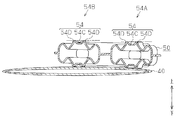
Links
Images







Classifications
-
- A—HUMAN NECESSITIES
- A61—MEDICAL OR VETERINARY SCIENCE; HYGIENE
- A61H—PHYSICAL THERAPY APPARATUS, e.g. DEVICES FOR LOCATING OR STIMULATING REFLEX POINTS IN THE BODY; ARTIFICIAL RESPIRATION; MASSAGE; BATHING DEVICES FOR SPECIAL THERAPEUTIC OR HYGIENIC PURPOSES OR SPECIFIC PARTS OF THE BODY
- A61H9/00—Pneumatic or hydraulic massage
- A61H9/005—Pneumatic massage
- A61H9/0078—Pneumatic massage with intermittent or alternately inflated bladders or cuffs
-
- A—HUMAN NECESSITIES
- A61—MEDICAL OR VETERINARY SCIENCE; HYGIENE
- A61H—PHYSICAL THERAPY APPARATUS, e.g. DEVICES FOR LOCATING OR STIMULATING REFLEX POINTS IN THE BODY; ARTIFICIAL RESPIRATION; MASSAGE; BATHING DEVICES FOR SPECIAL THERAPEUTIC OR HYGIENIC PURPOSES OR SPECIFIC PARTS OF THE BODY
- A61H2201/00—Characteristics of apparatus not provided for in the preceding codes
- A61H2201/01—Constructive details
- A61H2201/0119—Support for the device
- A61H2201/0138—Support for the device incorporated in furniture
- A61H2201/0149—Seat or chair
-
- A—HUMAN NECESSITIES
- A61—MEDICAL OR VETERINARY SCIENCE; HYGIENE
- A61H—PHYSICAL THERAPY APPARATUS, e.g. DEVICES FOR LOCATING OR STIMULATING REFLEX POINTS IN THE BODY; ARTIFICIAL RESPIRATION; MASSAGE; BATHING DEVICES FOR SPECIAL THERAPEUTIC OR HYGIENIC PURPOSES OR SPECIFIC PARTS OF THE BODY
- A61H2201/00—Characteristics of apparatus not provided for in the preceding codes
- A61H2201/16—Physical interface with patient
- A61H2201/1602—Physical interface with patient kind of interface, e.g. head rest, knee support or lumbar support
- A61H2201/1635—Hand or arm, e.g. handle
- A61H2201/1638—Holding means therefor
-
- A—HUMAN NECESSITIES
- A61—MEDICAL OR VETERINARY SCIENCE; HYGIENE
- A61H—PHYSICAL THERAPY APPARATUS, e.g. DEVICES FOR LOCATING OR STIMULATING REFLEX POINTS IN THE BODY; ARTIFICIAL RESPIRATION; MASSAGE; BATHING DEVICES FOR SPECIAL THERAPEUTIC OR HYGIENIC PURPOSES OR SPECIFIC PARTS OF THE BODY
- A61H2205/00—Devices for specific parts of the body
- A61H2205/06—Arms
Definitions
- the present invention relates to an air massage machine including an air bag and an armrest.
- an air massage machine including an armrest having a first armrest portion and a second armrest portion facing the first armrest portion with an arm arrangement space in between is known (for example, Patent Document 1).
- an air bag is disposed on at least one of the first armrest portion and the second armrest portion.
- the conventional air massage machine can only perform a monotonous massage in which an air bag presses the arm.
- An object of the present invention is to provide an air massage machine that can apply various stimuli to the arm.
- the air massage machine includes an armrest including a first armrest portion and a second armrest portion facing the first armrest portion with an arm placement space for placing an arm therebetween.
- An air massage machine is provided with the 1st air bag arrange
- the second airbag includes a stimulation part row including a plurality of stimulation parts arranged along a longitudinal direction of the armrest, and the plurality of stimulation parts can protrude toward the second armrest part. It is configured as follows.
- the stimulation unit row is one of a plurality of stimulation unit rows in the second airbag.
- the second airbag includes an outer peripheral portion provided around the stimulation portion row, and the plurality of stimulation portions are more than the outer peripheral portion when the second airbag is inflated most.
- the plurality of stimulating portions are located closer to the first armrest portion than the outer peripheral portion when the second airbag is most contracted, or the second stimulation portion is located close to the second armrest portion, or It is preferable to be located at a position separated from one armrest portion by the same distance as the outer peripheral portion.
- each of the plurality of stimulation units includes a first stimulation unit and a second stimulation unit
- the first airbag has two portions that are inflated with different expansion amounts toward the second armrest unit.
- the first stimulation unit and the second stimulation unit are respectively overlapped with two portions of the first airbag that are inflated with different expansion amounts toward the second armrest portion.
- the air massage machine includes a seat portion, the plurality of stimulation unit rows include a first stimulation unit row and a second stimulation unit row, and the first stimulation unit row includes the second stimulation unit.
- the armrests are arranged closer to the seat than the row, and the base end of the armrest is located closer to the seat than the tip of the armrest.
- the present invention provides an air massage machine that can apply various stimuli to the arm.
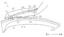
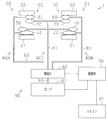
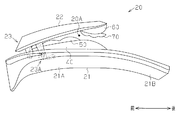
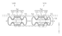
- FIG. 1 It is a perspective view of the air massage machine of an embodiment, and a perspective view showing the whole structure of an air massage machine. It is a front view of the armrest of an embodiment, and a front view showing the front structure of an armrest when an arm is arranged between the 1st armrest part and the 2nd armrest part. It is a schematic diagram of the air massage machine of embodiment, and is a schematic diagram which shows the relationship between each airbag and a supply system. It is a front view of the 1st armrest part of an embodiment, and is a front view showing the front structure of the 1st armrest part. It is a front view of the 2nd air bag of an embodiment, and a front view showing the front structure of the 2nd air bag. FIG.
- FIG. 6 is a cross-sectional view of the second airbag according to the embodiment, showing a cross-sectional structure taken along line Z6-Z6 of FIG. It is a front view of the 2nd armrest part of an embodiment, and a front view showing the front structure of the 2nd armrest part. It is a front view of the armrest of an embodiment, and a front view showing the front structure of an armrest when the 2nd armrest part is closest to the 1st armrest part. It is a front view of the armrest of an embodiment, and a front view showing the front structure of an armrest when the 2nd armrest part is the furthest away from the 1st armrest part.
- the air massage machine 1 is configured as a chair type massage machine.
- the air massage machine 1 has a main body 10, a supply device 80 (see FIG. 3), a control device 90 (see FIG. 3), and a remote controller 91.
- the main body 10 includes a seat portion 11 having a seating surface 11A, a backrest 12, an ottoman 13, and two armrests 20.
- the supply device 80 (see FIG. 3) and the control device 90 (see FIG. 3) are disposed inside the main body 10.
- the remote controller 91 is disposed at the right end of the main body 10.
- the massage machine 1 starts and ends massage by the operation of the user's remote control.
- the two armrests 20 have a right armrest 20 for placing the user's right arm 100 and a left armrest 20 for placing the user's left arm 100.
- the right armrest 20 is disposed adjacent to the right end of the seat 11 and the backrest 12.
- the left armrest 20 is disposed adjacent to the left end of the seat 11 and the backrest 12.
- the right armrest 20 and the left armrest 20 have symmetrical shapes.
- each armrest 20 has a first armrest portion 21, a second armrest portion 22, a rotation mechanism 23, and an airbag group 30.
- An arm placement space 20 ⁇ / b> A is formed between the first armrest portion 21 and the second armrest portion 22.
- the first armrest portion 21 has a forearm arrangement portion 21A provided at the distal end of the first armrest portion 21 and a main body fixing portion 21B provided at the base end of the first armrest portion 21.
- the forearm placement portion 21A has a length that allows the portion from the elbow to the fingertip of the user's arm 100 to be placed.
- the first armrest portion 21 is fixed to the seat portion 11.
- the second armrest portion 22 is provided above the first armrest portion 21.
- the second armrest portion 22 faces the forearm arrangement portion 21 ⁇ / b> A of the first armrest portion 21.
- a proximal end of the second armrest portion 22 is rotatably attached to the first armrest portion 21 via a rotation mechanism 23.
- the airbag group 30 is disposed between the first armrest portion 21 and the second armrest portion 22.
- the airbag group 30 includes a first airbag 40, a second airbag 50, a third airbag 60, and a fourth airbag 70.
- the first airbag 40, the second airbag 50, the third airbag 60, and the fourth airbag 70 are formed by, for example, blow molding.
- the first airbag 40 and the second airbag 50 are disposed on the upper surface of the first armrest portion 21.
- the third airbag 60 and the fourth airbag 70 are disposed on the lower surface of the second armrest portion 22.
- the first armrest portion 21 has a cloth-like cover (not shown) that covers the first airbag 40 and the second airbag 50.
- the second armrest portion 22 has a cloth-like cover (not shown) that covers the third airbag 60 and the fourth airbag 70.
- the supply device 80 includes a pump 81, a solenoid valve 82, and three tubes 83.
- the pump 81 is connected to two groups of airbags 30 through three tubes 83 and a solenoid valve 82. Air from the pump 81 is supplied to the two airbag groups 30 via the three tubes 83 and the electromagnetic valve 82.
- the first air bag 40 on the right side, the third air bag 60 on the right side, and the electromagnetic valve 82 are connected via a first supply system 80A.
- the left side first air bag 40 and the left side third air bag 60 are connected to the electromagnetic valve 82 via the second supply system 80B.
- the second airbag 50 on the right side, the fourth airbag 70 on the right side, the second airbag 50 on the left side, the fourth airbag 70 on the left side, and the solenoid valve 82 are connected via a third supply system 80C.
- the pump 81 is driven and stopped according to a control signal from the control device 90.
- the electromagnetic valve 82 supplies and discharges air in the first supply system 80A, the second supply system 80B, and the third supply system 80C based on a control signal from the control device 90.
- the supply device 80 supplies and discharges air in each of the supply systems 80A to 80C by a combination of the following (state A) to (state F) according to switching of the electromagnetic valve 82.
- (State A) The first supply system 80A and the pump 81 are connected, the second supply system 80B is opened to the atmosphere, and the third supply system 80C is opened to the atmosphere.
- (State B) The first supply system 80A and the pump 81 are connected, the second supply system 80B is opened to the atmosphere, and the third supply system 80C and the pump 81 are connected.
- State C The first supply system 80A is opened to the atmosphere, the second supply system 80B and the pump 81 are connected, and the third supply system 80C is opened to the atmosphere.
- (State D) The first supply system 80A is opened to the atmosphere, the second supply system 80B and the pump 81 are connected, and the third supply system 80C and the pump 81 are connected.
- (State E) The first supply system 80A is opened to the atmosphere, the second supply system 80B is opened to the atmosphere, and the third supply system 80C is opened to the atmosphere.
- (State F) The first supply system 80A is opened to the atmosphere, the second supply system 80B is opened to the atmosphere, and the third supply system 80C and the pump 81 are connected.
- the first airbag 40 covers almost the entire upper surface of the forearm arrangement portion 21 ⁇ / b> A of the first armrest portion 21.
- the first airbag 40 has a flat surface.
- a supply port 43 for connecting to the tube 83 is provided at the front end 41 of the first airbag 40.
- a front end 41 of the first airbag 40 is fixed to the first armrest portion 21.
- the second airbag 50 is arranged so as to be biased toward the tip of the first armrest portion 21.
- the second airbag 50 has an uneven surface.
- a supply port 53 for connecting to the tube 83 is provided at the front end 51 of the second airbag 50.
- a front end 51 of the second airbag 50 is fixed to the first armrest portion 21 and the first airbag 40.
- the second airbag 50 is stacked on the upper surface of the first airbag 40.
- the second airbag 50 is smaller than the first airbag 40.
- the front end 51 of the second airbag 50 is disposed in alignment with the front end 41 of the first airbag 40. Accordingly, the rear end 42 of the first airbag 40 protrudes beyond the rear end 52 of the second airbag 50.
- the second airbag 50 divides the twelve stimulation parts 54 protruding toward the second armrest part 22 and the twelve stimulation parts 54 into three stimulation parts 54. And four outer peripheral portions 55 respectively formed around the four stimulation regions formed by the above.
- first stimulation unit row 54A six of the twelve stimulation units 54 are arranged along the longitudinal direction of the armrest 20 to form a first stimulation unit row 54A.
- the remaining six stimulation parts 54 are arranged along the longitudinal direction of the armrest 20 adjacent to the first stimulation part row 54A to form the second stimulation part row 54B.
- the first stimulation part row 54A is formed closer to the seat part 11 than the second stimulation part row 54B.
- the rear end is located closer to the seat part 11 than the front end.
- Each stimulation part 54 has a side along the longitudinal direction that is longer than a side along the width direction of the armrest 20.
- the four outer peripheral portions 55 are arranged around the three stimulation portions 54 on the front end 51 side of the first stimulation portion row 54A, around the three stimulation portions 54 on the rear end 52 side of the first stimulation portion row 54A, and the second It is formed so as to surround the three stimulation parts 54 on the front end 51 side of the stimulation part row 54B and the three stimulation parts 54 on the rear end 52 side of the first stimulation part row 54A.
- Each outer peripheral portion 55 has a side along the longitudinal direction of the armrest 20 that is longer than the side along the width direction of the armrest 20.
- FIG. 6 shows a cross-sectional structure of the second airbag 50 when air to the second airbag 50 is blocked and no external pressure is applied to the second airbag 50.
- Each stimulator 54 has a central portion 54C and a protrusion 54D surrounding the central portion 54C.
- the central portion 54C of the stimulation portion 54 protrudes toward the second armrest portion 22 from the outer peripheral portion 55, that is, upward.
- the protruding portion 54D protrudes upward from the central portion 54C.
- the third airbag 60 is disposed so as to be biased toward the tip of the second armrest portion 22.
- the third airbag 60 has a flat surface.
- a supply port 63 for connecting to the tube 83 is provided at the front end 61 of the third airbag 60.
- a front end 61 of the third airbag 60 is fixed to the second armrest portion 22.
- the fourth airbag 70 is arranged so as to be biased toward the tip of the second armrest portion 22.
- the fourth airbag 70 has three air chambers 70 ⁇ / b> A arranged from the front end 61 toward the rear end 62.
- a supply port 63 for connecting to the tube 83 is provided at the front end 71 of the fourth airbag 70.
- a front end 71 of the fourth airbag 70 is fixed to the second armrest portion 22.
- the rear end 72 of the fourth airbag 70 is disposed in alignment with the rear end 62 of the third airbag 60.
- the fourth airbag 70 is stacked on the lower surface of the third airbag 60.
- the size of the fourth airbag 70 is substantially equal to the size of the third airbag 60.
- the front end 71 of the fourth airbag 70 is disposed in alignment with the front end 61 of the third airbag 60.
- the rotation mechanism 23 regulates the rotation of the second armrest portion 22 when the second armrest portion 22 rotates until the tip of the second armrest portion 22 reaches the position farthest from the first armrest portion 21. 23A. As shown in FIG. 8, the rotation mechanism 23 is positioned to allow rotation of the second armrest portion 22 relative to the first armrest portion 21, and as shown in FIG. 9, the second armrest portion 22 relative to the first armrest portion 21. Operates between the position where rotation is restricted.
- the rotation mechanism 23 has a first position where the tip of the second armrest 22 contacts the first armrest 21 around the base end of the second armrest 22 and the tip of the second armrest 22 is the first.
- the second armrest portion 22 is rotated between a second position separated from the position by a preset distance.
- the restriction mechanism 23 ⁇ / b> A restricts the rotation of the second armrest portion 22 when the tip of the second armrest portion 22 reaches the second position due to the rotation of the second armrest portion 22.
- the second armrest portion 22 uses the rotation mechanism 23 to center the proximal end of the second armrest portion 22 and the distal end of the second armrest portion 22. Rotates to the position closest to the first armrest portion 21. At this time, a minimum arm arrangement space 20 ⁇ / b> A is formed between the first armrest portion 21 and the second armrest portion 22.
- a minimum arm arrangement space 20 ⁇ / b> A is formed between the first armrest portion 21 and the second armrest portion 22.
- the second armrest portion 22 does not rotate upward.
- the second armrest portion 22 rotates upward.
- the second airbag 50 and the fourth airbag 70 are arranged so that the second airbag 50 and the fourth airbag 70 do not substantially overlap each other when the second armrest portion 22 comes closest to the first armrest portion 21. The For this reason, when the 2nd armrest part 22 approaches the 1st armrest part 21, the armrest 20 can be accommodated compactly in the height direction.
- the second armrest portion 22 uses the rotation mechanism 23 to center the base end of the second armrest portion 22 and the distal end of the second armrest portion 22 is first. Rotates to a position farthest from one armrest 21. At this time, the largest arm arrangement space 20 ⁇ / b> A is formed between the first armrest portion 21 and the second armrest portion 22.
- the restriction mechanism 23 ⁇ / b> A further rotates the second armrest portion 22 upward and downward. regulate.
- an arm 100 indicated by a two-dot chain line in FIG. 10 indicates an arm 100 shorter than the arm 100 indicated by a broken line.
- the stimulation part rows 54A and 54B of the second airbag 50 are arranged along the longitudinal direction of the arm 100 indicated by a two-dot chain line in FIG.
- the first stimulating part row 54A stimulates the arms 100 and the inside of the wrist and the base of the thumb.
- the second stimulation section row 54B stimulates the outside of the arm 100 and the wrist and the base portion of the little finger.
- the elbow of the short arm 100 indicated by a broken line is arranged closer to the seat portion 11 than the elbow of the long arm 100 indicated by a two-dot chain line. Since the second stimulating portion row 54B is formed from the outside toward the seat portion 11 (see FIG. 1) as it goes from the front end to the rear end, as shown by the broken line in FIG. It arrange
- restraint force A The force that prevents the arm 100 from moving relative to the armrest 20 when the first airbag 40 and the third airbag 60 are most inflated (hereinafter referred to as “restraint force A”) is that the second airbag 50 and the fourth airbag 70 It is larger than the restraining force A when it expands most.
- the restraining force A is the dimension of the airbag 40 to 70 in the thickness direction when the airbag 40 to 70 is inflated most, and the air in the thickness direction when the airbag 40 to 70 is most contracted. It is determined according to the difference from the dimensions of the bags 40 to 70 (hereinafter referred to as “expansion amount”) and the area of the air bags 40 to 70 facing the arm 100 (hereinafter referred to as “opposing area”).
- the restraining force A increases as the expansion amount increases, and increases as the facing area increases.
- the sum of the inflation amount of the first airbag 40 and the inflation amount of the third airbag 60 is larger than the sum of the inflation amount of the second airbag 50 and the inflation amount of the fourth airbag 70.
- the sum of the opposing area of the first airbag 40 and the opposing area of the third airbag 60 is larger than the sum of the opposing area of the second airbag 50 and the opposing area of the fourth airbag 70.
- the binding force A is defined as follows according to the airbag group 30.
- A1 The restraint force A when the first airbag 40, the third airbag 60, the second airbag 50, and the fourth airbag 70 are all inflated is defined as a restraint force A1.
- A2) The restraining force A2 when the first airbag 40 and the third airbag 60 are most inflated and the second airbag 50 and the fourth airbag 70 are most contracted is defined as a restraining force A2.
- A3 The restraining force A when the first airbag 40 and the third airbag 60 are most contracted and the second airbag 50 and the fourth airbag 70 are most inflated is defined as a restraining force A3.
- binding force A1> binding force A2> binding force A3> binding force A4 is established.
- the restraining force A is equal to or greater than the restraining force A2
- the movement of the arm 100 with respect to the armrest 20 is hindered by a strong force.
- the restraining force A is equal to or less than the restraining force A3, the arm 100 can easily move with respect to the armrest 20.
- the restraining force A between the restraining force A2 and the restraining force A3 corresponds to the “predetermined value of the restraining force”.
- 14 and 15 indicate the state of the second airbag 50 when no air is supplied from the second airbag 50 and no pressure is applied to the second airbag 50 from the outside. Show.
- the stimulation part 54 protrudes upward from the outer peripheral part 55. For this reason, the stimulation of the stimulation part 54 acts on the arm 100 more strongly than the stimulation of the outer peripheral part 55.
- the stimulation part 54 is recessed by contact with the arm 100, and the position of the outer peripheral part 55 and the stimulation part 54 in the thickness direction of the second airbag 50. It becomes equal to the position of the upper end of. For this reason, the stimulation of both the outer peripheral part 55 and the stimulation part 54 acts on the arm 100 strongly.
- the stimulation part 54 in the first stimulation part row 54A and the stimulation part 54 in the second stimulation part row 54B are inflated at different inflation amounts in the first airbag 40.
- the two parts are superimposed on each other.
- column 54B is located above the stimulation part 54 of 54 A of 1st stimulation part rows
- the stimulation unit 54 in the first stimulation unit row 54A corresponds to a “first stimulation unit”.
- the stimulation unit 54 in the second stimulation unit row 54B corresponds to a “second stimulation unit”.
- the plurality of stimulation sections 54 in the first and second stimulation section rows 54A and 54B are inflated with different expansion amounts in the first airbag 40.
- Each part is overlaid.
- positioned near the center in the longitudinal direction of the 1st airbag 40 is located above the stimulation part 54 arrange
- the contact pressure to the arm 100 of the stimulation unit 54 disposed near the center of the first airbag 40 in the longitudinal direction is such that the arm 100 of the stimulation unit 54 disposed at the end of the first airbag 40 in the longitudinal direction. It becomes larger than the contact pressure.
- the stimulation unit 54 disposed near the center in the longitudinal direction of the first airbag 40 corresponds to a “first stimulation unit”.
- the stimulation part 54 arranged at the end in the longitudinal direction of the first airbag 40 corresponds to a “second stimulation part”.
- the position of the stimulation unit 54 in the first stimulation unit row 54A and the position of the stimulation unit 54 in the second stimulation unit row 54B are as follows. 1 It becomes substantially equal in the thickness direction of the airbag 40. That is, the contact pressure to the arm 100 of the stimulation part 54 in the first stimulation part row 54A is substantially equal to the contact pressure to the arm 100 of the stimulation part 54 in the second stimulation part row 54B.
- the position of the stimulation part 54 in the first stimulation part row 54A and the second stimulation part row 54B in the thickness direction of the first airbag 40 The relationship with the position is different. Therefore, different stimuli can be applied to the arm 100 when the first airbag 40 is inflated and when it is contracted.
- the supply device 80 switches the electromagnetic valve 82 to supply and discharge air according to “state A”. Thereby, the first airbag 40 on the right side and the third airbag 60 on the right side start inflating.
- the supply device 80 switches the electromagnetic valve 82 to change the air in “state B”. Supply and discharge.
- the supply device 80 switches the electromagnetic valve 82 to supply and discharge air in “state A”. I do.
- the supply device 80 switches the electromagnetic valve 82 to supply and discharge air according to “state B”. I do.
- the supply device 80 switches the electromagnetic valve 82 in the same manner as from time t13 to time t14.
- the supply device 80 switches the electromagnetic valve 82 to supply and discharge air in “state E”. I do.
- the supply device 80 switches the solenoid valve 82 to change the air in “state C”. Supply and discharge. Thereby, the first airbag 40 on the left side and the third airbag 60 on the right side start inflating.
- the supply device 80 switches the electromagnetic valve 82 to change the air in “state D”. Supply and discharge.
- the supply device 80 switches the electromagnetic valve 82 to supply and discharge air in “state C”. I do.
- the supply device 80 switches the electromagnetic valve 82 to supply and discharge air according to “state D”. I do.
- the supply device 80 switches the electromagnetic valve 82 in the same manner as from time t23 to time t24.
- the supply device 80 switches the electromagnetic valve 82 to supply and discharge air in “state E”. I do.
- the air massage machine 1 of the present embodiment has the following effects.
- the air massage machine 1 has a plurality of stimulation units 54. For this reason, the air massage machine 1 can give various stimuli to the user's arm 100.
- the plurality of stimulation parts 54 are arranged along the longitudinal direction of the armrest 20 to form stimulation part rows 54A and 54B. For this reason, even when the user's arm 100 is short, or when using the air massage machine 1 with the backrest 12 tilted, the stimulation unit 54 is likely to contact the user's arm 100. For this reason, compared with the air massage machine which has the independent irritation
- the second airbag 50 has a first stimulation part row 54A and a second stimulation part row 54B.
- the first stimulation part row 54A can stimulate the inside of the arm 100 and the wrist and the base part of the thumb.
- the second stimulation section row 54B can stimulate the arm 100 and the outside of the wrist and the base portion of the little finger.
- the stimulating unit 54 applies a large contact pressure to the arm 100. Further, when the second airbag 50 is most contracted, the outer peripheral portion 55 applies a large contact pressure to the arm 100. That is, since the site
- the stimulation part 54 in the first stimulation part row 54A and the stimulation part 54 in the second stimulation part row 54B are respectively overlapped on two parts of the first airbag 40 that are inflated with different expansion amounts. For this reason, when the first airbag 40 contracts, the stimulation unit 54 of the first stimulation unit row 54A applies the same contact pressure to the arm 100 as the stimulation unit 54 of the second stimulation unit row 54B.
- the stimulation unit 54 in the second stimulation unit row 54B applies a larger contact pressure to the arm 100 than the stimulation unit 54 in the first stimulation unit row 54A. That is, there is a difference in contact pressure between the stimulation unit 54 in the first stimulation unit row 54A and the stimulation unit 54 in the second stimulation unit row 54B between the inflated first airbag 40 and the contracted first airbag 40. As a result, various stimuli can be given to the user.
- the airbag group 30 provided in each of the right armrest 20 and the left armrest 20 includes a first airbag 40, a second airbag 50, a third airbag 60, and a fourth airbag 70.
- Air is supplied to the first airbag 40 of the right armrest 20 and the third airbag 60 of the right armrest 20 by the first supply system 80A.
- Air is supplied to the first airbag 40 of the left armrest 20 and the third airbag 60 of the left armrest 20 by the second supply system 80B.
- a third supply is provided to the second airbag 50 of the right armrest 20, the fourth airbag 70 of the right armrest 20, the second airbag 50 of the left armrest 20, and the fourth airbag 70 of the left armrest 20.
- Air is supplied by the system 80C.
- the air massage machine 1 can achieve both a variety of massages and a reduction in the number of supply systems 80A to 80C.
- the air massage machine 1 executes the supply of air to the first supply system 80A and the supply of air to the second supply system 80B at different times so as to be smaller. For this reason, when the user massages one of the right arm 100 and the left arm 100 with a large restraining force A, the user can freely move the other of the right arm 100 and the left arm 100. it can. Thereby, a user's convenience can be improved.
- the second airbag 50 and the fourth airbag 70 are arranged to face each other so that the second airbag 50 overlaps a part of the fourth airbag 70. For this reason, the binding force A when the second airbag 50 and the fourth airbag 70 are inflated most is smaller than the configuration in which the entire second airbag 50 is disposed so as to overlap the fourth airbag 70. Become.
- the second armrest portion 22 is disposed above the first armrest portion 21 and is rotatably attached to the first armrest portion 21 with the base end of the second armrest portion 22 as the center. Further, the second airbag 50 and the fourth airbag 70 are arranged so as not to overlap when the second airbag 50 and the fourth airbag 70 face each other. For this reason, an armrest can be accommodated compactly.
- the second airbag 50 of the first armrest portion 21 is overlapped with the upper surface of the first airbag 40 in the thickness direction. Further, the fourth airbag 70 of the second armrest portion 22 is overlapped with the lower surface of the third airbag 60 in the thickness direction.
- the present invention includes embodiments other than the above embodiment.
- the modification of the said embodiment as other embodiment of this invention is shown.
- the following modifications can be combined with each other.
- the second airbag 50 of the embodiment has a first stimulation part row 54A and a second stimulation part row 54B.
- one of the first stimulation part row 54A and the second stimulation part row 54B may be omitted.
- the second airbag 50 of the embodiment has a first stimulation part row 54A and a second stimulation part row 54B.
- the second airbag 50 of the modified example may have three or more stimulating part rows.
- the second airbag 50 has a plurality of stimulation parts 54.
- at least one of the first airbag 40, the third airbag 60, and the fourth airbag 70 in addition to the second airbag 50 has one or a plurality of stimulation parts 54. May be.
- the stimulation part 54 of the first stimulation part row 54 ⁇ / b> A and the stimulation part 54 of the second stimulation part row 54 ⁇ / b> B of the embodiment are in the direction from the first armrest part 21 of the first airbag 40 toward the second armrest part 22. It is superimposed on two parts that expand with different expansion amounts.
- the stimulation part 54 of the first stimulation part row 54 ⁇ / b> A and the stimulation part 54 of the second stimulation part row 54 ⁇ / b> B in the modification are directions from the first armrest part 21 to the second armrest part 22 in the first airbag 40. May be overlaid on two parts that expand with the same expansion amount.
- the stimulation part 54 when the second airbag 50 is inflated most, the stimulation part 54 applies a large contact pressure to the arm 100, and when the second airbag 50 is contracted most, the outer peripheral part 55 applies a large contact pressure to the arm 100.
- the stimulating unit 54 applies a larger contact pressure to the arm 100 than the outer peripheral unit 55 in both cases where the second airbag 50 is inflated and contracted most.
- the stimulation part 54 is located closer to the second armrest part 22 than the outer peripheral part 55 when the protrusion 54D contracts most.
- the rear end of the second stimulation part row 54B is disposed closer to the seat part 11 than the front end.
- the front end of the second stimulation part row 54B is disposed closer to the seat part 11 than the rear end.
- the distance between the rear end of the second stimulation part row 54B and the seat part 11 is the distance between the front end of the second stimulation part row 54B and the seat part 11. equal.
- the supply device 80 of the embodiment supplies air to the eight airbags 40 to 70 through the three supply systems 80A to 80C.
- the supply device 80 of the modified example may supply air to the eight airbags 40 to 70 by one, two, or four or more supply systems.
- air is supplied and discharged by one supply system for one airbag.
- at least one airbag 40 to 70 that supplies air by the same supply system is appropriately selected.
- the air massage machine 1 of the embodiment executes the supply of air to the first supply system 80A and the supply of air to the second supply system 80B at different times.
- the air massage machine 1 of the modified example may execute the supply of air to the first supply system 80A and the supply of air to the second supply system 80B at the same time.
- the first airbag 40 and the third airbag 60 are inflated most in one of the right armrest 20 and the left armrest 20, and the other of the right armrest 20 and the left armrest 20 is the other.
- the supply of air to the third supply system 80C and the discharge of air from the third supply system 80C are executed.
- the first air bag 40 and the third air bag 60 are inflated by supplying air to the first air bag 40 and the third air bag 60, or the first air massage machine 1 of the modification example.
- the supply of air to the third supply system 80C and the third supply system 80C are performed. Air is discharged from the air.
- the electromagnetic valve 82 of the embodiment opens the four airbags 40 to 70 to the atmosphere when the air is discharged from the four airbags 40 to 70.
- the electromagnetic valve 82 of the modified example discharges air from the four airbags 40 to 70
- the four airbags 40 to 70 are connected to the discharge device, and the air is shortened from the four airbags 40 to 70. It may be discharged in time.
- the first airbag 40 overlaps the fourth airbag 70 in the direction from the second armrest portion 22 toward the first armrest portion 21.
- the first airbag 40 may not overlap with the fourth airbag 70 in the direction from the second armrest portion 22 to the first armrest portion 21.
- the sum of the inflation amount of the first airbag 40 and the inflation amount of the third airbag 60 is larger than the sum of the inflation amount of the second airbag 50 and the inflation amount of the fourth airbag 70.
- the sum of the inflated amount of the first airbag 40 and the inflated amount of the third airbag 60 in the modified example is smaller than the sum of the inflated amount of the second airbag 50 and the inflated amount of the fourth airbag 70.
- the sum of the opposing area of the first airbag 40 and the opposing area of the third airbag 60 in the embodiment is larger than the sum of the opposing area of the second airbag 50 and the opposing area of the fourth airbag 70.
- the sum of the opposing area of the first airbag 40 and the opposing area of the third airbag 60 of the modification is smaller than the sum of the opposing area of the second airbag 50 and the opposing area of the fourth airbag 70.
- the second armrest portion 22 is attached to the upper side of the first armrest portion 21.
- the armrest 20 of the modification has a second armrest portion 22 attached to the lower side of the first armrest portion 21.
- the armrest 20 of the embodiment has a first armrest portion 21 and a second armrest portion 22 that sandwich the arm 100 in the height direction of the air massage machine 1.
- the armrest 20 of the modified example has a groove into which the arm 100 is fitted.
- one of the right side wall and the left side wall of the groove corresponds to the “first armrest”
- the other of the right side wall and the left side wall of the groove corresponds to the “second armrest”.
- the second armrest portion 22 of the embodiment is attached to the first armrest portion 21 so as to be rotatable around the base end of the second armrest portion 22.
- the second armrest portion 22 of the modification may be fixed to the first armrest portion 21. In this case, it is fixed to the first armrest portion 21 in a state where the maximum arm arrangement space 20A is formed.
- the second airbag 50 and the fourth airbag 70 of the embodiment are arranged alternately so as not to overlap when facing each other.
- the second airbag 50 and the fourth airbag 70 according to the modification may be arranged such that the rear end 52 of the second airbag 50 and the front end 71 of the fourth airbag 70 overlap each other when facing each other.
- the second airbag 50 and the fourth airbag 70 of a further modification may be arranged such that the entire fourth airbag 70 overlaps the second airbag 50 when facing each other.
- the air massage machine 1 is a chair-type air massage machine 1 and includes a seat portion 11, a backrest 12, and an ottoman 13.
- a seat portion 11, a backrest 12, and an ottoman 13 On the other hand, in the air massage machine of the modified example, at least one of the seat portion 11, the backrest 12, and the ottoman 13 may be omitted.
- the modified air massage machine 1 is used by placing the armrest 20 on a table or the like.
Landscapes
- Health & Medical Sciences (AREA)
- Epidemiology (AREA)
- Pain & Pain Management (AREA)
- Physical Education & Sports Medicine (AREA)
- Rehabilitation Therapy (AREA)
- Life Sciences & Earth Sciences (AREA)
- Animal Behavior & Ethology (AREA)
- General Health & Medical Sciences (AREA)
- Public Health (AREA)
- Veterinary Medicine (AREA)
- Massaging Devices (AREA)
Description
本発明は、エアーバッグおよび肘掛を備えるエアーマッサージ機に関する。
従来、第1肘掛部と、腕配置空間を挟んで第1肘掛部に対向する第2肘掛部とを有する肘掛を備えたエアーマッサージ機が知られている(例えば、特許文献1)。この種のエアーマッサージ機では、第1肘掛部および第2肘掛部の少なくとも一方にエアーバッグが配置されている。
上記従来のエアーマッサージ機は、エアーバッグが腕を圧迫する単調なマッサージしか行うことができない。
本発明の目的は、多彩な刺激を腕に付与することのできるエアーマッサージ機を提供することである。
本発明の一側面は、エアーマッサージ機である。エアーマッサージ機は、第1肘掛部と、腕を配置するための腕配置空間を挟んで前記第1肘掛部と対向する第2肘掛部とを含む肘掛を備える。エアーマッサージ機は、前記第1肘掛部に配置された第1エアーバッグと、前記第1エアーバッグの少なくとも一部と重ねて配置された第2エアーバッグとを備える。前記第2エアーバッグは、前記肘掛の長手方向に沿って配置された複数の刺激部からなる刺激部列を含み、前記複数の刺激部は、前記第2肘掛部に向かって突出することができるように構成されている。
上記構成において、前記刺激部列は、前記第2エアーバッグにおける複数の刺激部列の一つであることが好ましい。
上記構成において、前記第2エアーバッグは、前記刺激部列の周囲に設けられた外周部を含み、前記複数の刺激部は、前記第2エアーバッグが最も膨張するとき、前記外周部よりも前記第2肘掛部に近接して位置し、前記複数の刺激部は、前記第2エアーバッグが最も収縮するとき、前記外周部よりも前記第1肘掛部に近接して位置するか、または前記第1肘掛部から前記外周部と同じ距離だけ離間した位置に位置することが好ましい。
上記構成において、前記複数の刺激部の各々は、第1刺激部および第2刺激部を含み、前記第1エアーバッグは、前記第2肘掛部に向かって異なる膨張量で膨張する2つの部分を含み、前記第1刺激部および前記第2刺激部は、前記第1エアーバッグのうちの前記第2肘掛部に向かって異なる膨張量で膨張する2つの部分にそれぞれ重ねられることが好ましい。
上記構成において、前記エアーマッサージ機は、座部を備え、前記複数の刺激部列は、第1刺激部列および第2刺激部列を含み、前記第1刺激部列は、前記第2刺激部列よりも前記座部に近接して配置され、前記肘掛の基端が、前記肘掛の先端よりも前記座部に近接して位置することが好ましい。
本発明は、多彩な刺激を腕に付与することのできるエアーマッサージ機を提供する。
図1に示されるように、エアーマッサージ機1は、椅子型のマッサージ機として構成される。
エアーマッサージ機1は、本体10、供給装置80(図3参照)、制御装置90(図3参照)、およびリモコン91を有する。
本体10は、座面11Aを有する座部11、背もたれ12、オットマン13、および2つの肘掛20を有する。
供給装置80(図3参照)、および制御装置90(図3参照)は、本体10の内部に配置される。リモコン91は、本体10の右側端部に配置される。マッサージ機1は、使用者のリモコンの操作によりマッサージを開始および終了する。
2つの肘掛20は、使用者の右腕100を置くための右側の肘掛20、および使用者の左腕100を置くための左側の肘掛20を有する。右側の肘掛20は、座部11および背もたれ12の右側端部と隣接して配置される。左側の肘掛20は、座部11および背もたれ12の左側端部と隣接して配置される。右側の肘掛20および左側の肘掛20は、互いに左右対称の形状を有する。
図2に示されるように、各肘掛20は、第1肘掛部21、第2肘掛部22、回転機構23、およびエアーバッグ群30を有する。また、第1肘掛部21および第2肘掛部22の間に、腕配置空間20Aが形成されている。
第1肘掛部21は、第1肘掛部21の先端に設けられた前腕配置部分21Aと、第1肘掛部21の基端に設けられた本体固定部分21Bを有する。前腕配置部分21Aは、使用者の腕100のうちの肘から指先までの部分を配置できる長さを有する。第1肘掛部21は、座部11に固定される。
第2肘掛部22は、第1肘掛部21の上方に設けられる。第2肘掛部22は、第1肘掛部21の前腕配置部分21Aに対向する。第2肘掛部22の基端は、回転機構23を介して第1肘掛部21に回転自在に取り付けられる。
エアーバッグ群30は、第1肘掛部21および第2肘掛部22の間に配置される。エアーバッグ群30は、第1エアーバッグ40、第2エアーバッグ50、第3エアーバッグ60、および第4エアーバッグ70を有する。第1エアーバッグ40、第2エアーバッグ50、第3エアーバッグ60、および第4エアーバッグ70は、例えばブロー成形により形成される。
第1エアーバッグ40および第2エアーバッグ50は、第1肘掛部21の上面に配置される。第3エアーバッグ60および第4エアーバッグ70は、第2肘掛部22の下面に配置される。なお、第1肘掛部21は、第1エアーバッグ40および第2エアーバッグ50を覆う布状のカバー(図示略)を有する。第2肘掛部22は、第3エアーバッグ60および第4エアーバッグ70を覆う布状のカバー(図示略)を有する。
図3に示されるように、供給装置80は、ポンプ81、電磁弁82、および3つのチューブ83を有する。
ポンプ81は、3つのチューブ83および電磁弁82を介して2つのエアーバッグ群30群に接続される。ポンプ81からのエアーが、3つのチューブ83および電磁弁82を介して2つのエアーバッグ群30に供給される。
右側の第1エアーバッグ40および右側の第3エアーバッグ60と、電磁弁82とは、第1供給系統80Aを介して接続される。
左側の第1エアーバッグ40および左側の第3エアーバッグ60と、電磁弁82とは、第2供給系統80Bを介して接続される。
右側の第2エアーバッグ50、右側の第4エアーバッグ70、左側の第2エアーバッグ50、および左側の第4エアーバッグ70と、電磁弁82とは、第3供給系統80Cを介して接続される。
ポンプ81は、制御装置90からの制御信号に応じて駆動および停止を行う。
電磁弁82は、制御装置90からの制御信号に基づいて第1供給系統80A、第2供給系統80B、および第3供給系統80Cにおけるエアーの供給および排出を行う。
供給装置80は、電磁弁82の切り替えに応じた以下の(状態A)~(状態F)の組み合わせで各供給系統80A~80Cにおけるエアーの供給および排出を行う。
(状態A)第1供給系統80Aとポンプ81とを接続し、第2供給系統80Bを大気開放し、第3供給系統80Cを大気開放する。
(状態B)第1供給系統80Aとポンプ81とを接続し、第2供給系統80Bを大気開放し、第3供給系統80Cとポンプ81とを接続する。
(状態C)第1供給系統80Aを大気開放し、第2供給系統80Bとポンプ81とを接続し、第3供給系統80Cを大気開放する。
(状態D)第1供給系統80Aを大気開放し、第2供給系統80Bとポンプ81とを接続し、第3供給系統80Cとポンプ81とを接続する。
(状態E)第1供給系統80Aを大気開放し、第2供給系統80Bを大気開放し、第3供給系統80Cを大気開放する。
(状態F)第1供給系統80Aを大気開放し、第2供給系統80Bを大気開放し、第3供給系統80Cとポンプ81とを接続する。
(状態A)第1供給系統80Aとポンプ81とを接続し、第2供給系統80Bを大気開放し、第3供給系統80Cを大気開放する。
(状態B)第1供給系統80Aとポンプ81とを接続し、第2供給系統80Bを大気開放し、第3供給系統80Cとポンプ81とを接続する。
(状態C)第1供給系統80Aを大気開放し、第2供給系統80Bとポンプ81とを接続し、第3供給系統80Cを大気開放する。
(状態D)第1供給系統80Aを大気開放し、第2供給系統80Bとポンプ81とを接続し、第3供給系統80Cとポンプ81とを接続する。
(状態E)第1供給系統80Aを大気開放し、第2供給系統80Bを大気開放し、第3供給系統80Cを大気開放する。
(状態F)第1供給系統80Aを大気開放し、第2供給系統80Bを大気開放し、第3供給系統80Cとポンプ81とを接続する。
図4に示されるように、第1エアーバッグ40は、第1肘掛部21の前腕配置部分21Aの上面のほぼ全体を覆う。第1エアーバッグ40は、平坦な形状の表面を有する。第1エアーバッグ40の前端41には、チューブ83と接続するための供給口43が設けられる。第1エアーバッグ40の前端41は、第1肘掛部21に固定される。
第2エアーバッグ50は、第1肘掛部21の先端に偏って配置される。第2エアーバッグ50は、凸凹形状の表面を有する。第2エアーバッグ50の前端51には、チューブ83と接続するための供給口53が設けられる。第2エアーバッグ50の前端51は、第1肘掛部21および第1エアーバッグ40に固定される。
第2エアーバッグ50は、第1エアーバッグ40の上面に重ねられる。第2エアーバッグ50は、第1エアーバッグ40よりも小さい。第2エアーバッグ50の前端51は、第1エアーバッグ40の前端41に合わせて配置される。従って、第1エアーバッグ40の後端42は、第2エアーバッグ50の後端52よりも突出している。
図5に示されるように、第2エアーバッグ50は、第2肘掛部22に向かって突出する12個の刺激部54と、12個の刺激部54を3個の刺激部54毎に区分けすることにより形成された4つの刺激領域の周りにそれぞれ形成される4つの外周部55を有する。
詳しくは、12個の刺激部54のうち6個の刺激部54は、肘掛20の長手方向に沿って配置されて、第1刺激部列54Aを形成する。残りの6個の刺激部54は、第1刺激部列54Aと隣接して肘掛20の長手方向に沿って配置されて、第2刺激部列54Bを形成する。第1刺激部列54Aは、第2刺激部列54Bよりも座部11に近接して形成される。第2刺激部列54Bでは、後端が前端よりも座部11に近接して位置する。各刺激部54は、肘掛20の幅方向に沿った辺よりも長い長手方向に沿った辺を有する。
4つの外周部55は、第1刺激部列54Aの前端51側の3つの刺激部54の周りと、第1刺激部列54Aの後端52側の3つの刺激部54の周りと、第2刺激部列54Bの前端51側の3つの刺激部54の周りと、第1刺激部列54Aの後端52側の3つの刺激部54の周りを囲んで形成される。各外周部55は、肘掛20の幅方向に沿った辺よりも長い肘掛20の長手方向に沿った辺を有する。
図6は、第2エアーバッグ50へのエアーが遮断され、且つ第2エアーバッグ50に外圧が付与されていない場合の第2エアーバッグ50の断面構造を示す。
各刺激部54は、中央部54Cおよび中央部54Cを囲む突起部54Dを有する。刺激部54の中央部54Cは、外周部55よりも第2肘掛部22に向かって、すなわち上方に突出する。突起部54Dは、中央部54Cよりも上方に突出する。
図7に示されるように、第3エアーバッグ60は、第2肘掛部22の先端に偏って配置される。第3エアーバッグ60は、平坦な形状の表面を有する。第3エアーバッグ60の前端61には、チューブ83と接続するための供給口63が設けられる。第3エアーバッグ60の前端61は、第2肘掛部22に固定される。
第4エアーバッグ70は、第2肘掛部22の先端に偏って配置される。第4エアーバッグ70は、前端61から後端62に向かって並ぶ3つの空気室70Aを有する。第4エアーバッグ70の前端71には、チューブ83と接続するための供給口63が設けられる。第4エアーバッグ70の前端71は、第2肘掛部22に固定される。第4エアーバッグ70の後端72は、第3エアーバッグ60の後端62に合わせて配置される。
第4エアーバッグ70は、第3エアーバッグ60の下面に重ねられる。第4エアーバッグ70の大きさは、第3エアーバッグ60の大きさとほぼ等しい。第4エアーバッグ70の前端71は、第3エアーバッグ60の前端61に合わせて配置される。
図8および図9を参照して、回転機構23の動作について説明する。
回転機構23は、第2肘掛部22の先端が第1肘掛部21に対して最も離れる位置に到達するまで第2肘掛部22が回転したとき、第2肘掛部22の回転を規制する規制機構23Aを有する。回転機構23は、図8に示されるように第2肘掛部22の第1肘掛部21に対する回転を許容する位置と、図9に示されるように第2肘掛部22の第1肘掛部21に対する回転を規制する位置との間で動作する。
即ち、回転機構23は、第2肘掛部22の基端を中心にして第2肘掛部22の先端が第1肘掛部21と当接する第1位置と、第2肘掛部22の先端が第1位置から予め設定された距離だけ離れた第2位置との間で第2肘掛部22を回転させる。規制機構23Aは、第2肘掛部22の回転により第2肘掛部22の先端が第2位置に到達したとき、第2肘掛部22の回転を規制する。
図8に示されるように、腕100のマッサージを行わないとき、第2肘掛部22は、回転機構23を用いて、第2肘掛部22の基端を中心にして第2肘掛部22の先端が第1肘掛部21に対して最も近づく位置に回転する。このとき、第1肘掛部21と第2肘掛部22との間には、最小の腕配置空間20Aが形成される。第2肘掛部22の先端が第1肘掛部21に対して最も近づく位置に回転したとき、第1肘掛部21および第1および第2エアーバック40,50と、第2肘掛部22および第3および第4エアーバック60,70とが接触することにより、第2肘掛部22がさらに下方に回転しない。また、第2肘掛部22および第3および第4エアーバック60,70の重さにより、第2肘掛部22が上方に回転しない。一方、使用者が第2肘掛部22の先端を持ち上げたときは、第2肘掛部22は、上方へ回転する。
第2エアーバッグ50および第4エアーバッグ70は、第2肘掛部22が第1肘掛部21に最も近づいたときに第2エアーバッグ50および第4エアーバッグ70が互いにほぼ重ならないように配置される。このため、第2肘掛部22が第1肘掛部21に最も近づいたとき、肘掛20は高さ方向においてコンパクトに収容できる。
図9に示されるように、腕100のマッサージを行うとき、第2肘掛部22は、回転機構23を用いて第2肘掛部22の基端を中心にして第2肘掛部22の先端が第1肘掛部21に対して最も離れる位置に回転する。このとき、第1肘掛部21と第2肘掛部22との間には、最大の腕配置空間20Aが形成される。第2肘掛部22の先端が第1肘掛部21に対して最も離れる位置にまで第2肘掛部22が回転したとき、規制機構23Aは、第2肘掛部22の上方および下方へのさらなる回転を規制する。
図10を参照して、腕配置空間20Aに腕100が配置されるときの腕100と第2エアーバッグ50との関係について説明する。なお、図10の二点鎖線の腕100は、破線の腕100よりも短い腕100を示している。
第2エアーバッグ50の刺激部列54A、54Bは、図10の二点鎖線で示される腕100の長手方向に沿って配置される。腕100の指先を肘掛20の先端に合わせて配置したとき、第1刺激部列54Aは、腕100および手首の内側と、親指の付け根部分とを刺激する。第2刺激部列54Bは、腕100および手首の外側と、小指の付け根部分とを刺激する。
破線で示す短い腕100の肘は、二点鎖線で示す長い腕100の肘よりも座部11に近接して配置される。第2刺激部列54Bは、前端から後端に向かうにつれて外側から座部11(図1参照)側に向かって形成されるため、図10の破線で示されるように、短い腕100は、第2エアーバッグ50の刺激部列54A、54Bに沿うように肘掛20に配置される。
エアーバッグ群30の動作について説明する。
図11に示されるように、第1エアーバッグ40および第3エアーバッグ60にエアーが供給され、第2エアーバッグ50および第4エアーバッグ70からエアーが排出されるとき、第1エアーバッグ40および第3エアーバッグ60が膨張し、第2エアーバッグ50および第4エアーバッグ70は収縮する。
図12に示されるように、第1エアーバッグ40および第3エアーバッグ60にエアーが供給され、第2エアーバッグ50および第4エアーバッグ70にエアーが供給されるとき、第1エアーバッグ40、第3エアーバッグ60、第2エアーバッグ50、および第4エアーバッグ70は膨張する。
図13に示されるように、第1エアーバッグ40および第3エアーバッグ60からエアーが排出され、第2エアーバッグ50および第4エアーバッグ70にエアーが供給されるとき、第1エアーバッグ40および第3エアーバッグ60は収縮し、第2エアーバッグ50および第4エアーバッグ70は膨張する。
第1エアーバッグ40および第3エアーバッグ60が最も膨張したときの腕100の肘掛20に対する移動を妨げる力(以下、「拘束力A」)は、第2エアーバッグ50および第4エアーバッグ70が最も膨張したときの拘束力Aよりも大きい。
具体的には、拘束力Aは、エアーバッグ40~70が最も膨張する際の厚さ方向におけるエアーバッグ40~70の寸法、およびエアーバッグ40~70が最も収縮する際の厚さ方向におけるエアーバッグ40~70の寸法との差(以下、「膨張量」)、およびエアーバッグ40~70のうちの腕100と対向する部分の面積(以下、「対向面積」)に応じて決定される。拘束力Aは、膨張量が大きいほど大きく、対向面積が大きいほど大きい。
第1エアーバッグ40の膨張量および第3エアーバッグ60の膨張量の和は、第2エアーバッグ50の膨張量および第4エアーバッグ70の膨張量の和よりも大きい。
第1エアーバッグ40の対向面積および第3エアーバッグ60の対向面積の和は、第2エアーバッグ50の対向面積および第4エアーバッグ70の対向面積の和よりも大きい。
エアーバッグ群30に応じて拘束力Aを以下のように定義する。
(A1)第1エアーバッグ40、第3エアーバッグ60、第2エアーバッグ50、および第4エアーバッグ70の全てが最も膨張しているときの拘束力Aを拘束力A1とする。
(A2)第1エアーバッグ40および第3エアーバッグ60が最も膨張し、かつ第2エアーバッグ50および第4エアーバッグ70が最も収縮しているときの拘束力Aを拘束力A2とする。
(A3)第1エアーバッグ40および第3エアーバッグ60が最も収縮し、かつ第2エアーバッグ50および第4エアーバッグ70が最も膨張しているときの拘束力Aを拘束力A3とする。
(A4)第1エアーバッグ40、第3エアーバッグ60、第2エアーバッグ50、および第4エアーバッグ70の全てが最も収縮しているときの拘束力Aを拘束力A4とする。
(A1)第1エアーバッグ40、第3エアーバッグ60、第2エアーバッグ50、および第4エアーバッグ70の全てが最も膨張しているときの拘束力Aを拘束力A1とする。
(A2)第1エアーバッグ40および第3エアーバッグ60が最も膨張し、かつ第2エアーバッグ50および第4エアーバッグ70が最も収縮しているときの拘束力Aを拘束力A2とする。
(A3)第1エアーバッグ40および第3エアーバッグ60が最も収縮し、かつ第2エアーバッグ50および第4エアーバッグ70が最も膨張しているときの拘束力Aを拘束力A3とする。
(A4)第1エアーバッグ40、第3エアーバッグ60、第2エアーバッグ50、および第4エアーバッグ70の全てが最も収縮しているときの拘束力Aを拘束力A4とする。
拘束力A1~A4においては、「拘束力A1>拘束力A2>拘束力A3>拘束力A4」の関係が成立する。拘束力Aが拘束力A2以上のとき、腕100の肘掛20に対する移動が強い力で妨げられる。一方、拘束力Aが拘束力A3以下のとき、腕100は、肘掛20に対して簡単に移動できる。なお、拘束力A2かつ拘束力A3の間の拘束力Aが「拘束力の所定値」に相当する。
図14および図15を参照して、刺激部54の作用について説明する。なお、図14および図15の二点鎖線は、第2エアーバッグ50からエアーが供給されず、かつ第2エアーバッグ50に外から圧力が付加されていないときの第2エアーバッグ50の状態を示している。
図14に示されるように、第2エアーバッグ50が最も膨張するとき、外周部55よりも刺激部54が上方に突出する。このため、刺激部54の刺激が外周部55の刺激よりも腕100に強く作用する。
図15に示されるように、第2エアーバッグ50が最も収縮するとき、腕100との接触により刺激部54が凹み、第2エアーバッグ50の厚さ方向において外周部55の位置と刺激部54の上方の端部の位置とは等しくなる。このため、外周部55および刺激部54の両方の刺激が腕100に強く作用する。
第1エアーバッグ40と第2エアーバッグ50との関係について説明する。
図16に示されるように、第1エアーバッグ40は、平坦な形状の表面を有するため、第1エアーバッグ40が膨張したとき、幅方向の中央部分および長手方向の中央部分が最も大きくなる。
第1エアーバッグ40が膨張しているとき、第1刺激部列54Aの刺激部54と、第2刺激部列54Bの刺激部54とが、第1エアーバッグ40のうちの異なる膨張量で膨張する2つの部分にそれぞれ重ねられている。このため、第2刺激部列54Bの刺激部54が、第1刺激部列54Aの刺激部54よりも上方に位置する。すなわち、第2刺激部列54Bの刺激部54による腕100への刺激の強さである接触圧力が、第1刺激部列54Aの刺激部54の腕100への接触圧力よりも大きくなる。なお、この場合、第1刺激部列54Aの刺激部54は、「第1刺激部」に相当する。第2刺激部列54Bの刺激部54は、「第2刺激部」に相当する。
また、第1エアーバッグ40が膨張しているとき、第1および第2の刺激部列54A、54Bにおける複数の刺激部54は、第1エアーバッグ40のうちの異なる膨張量で膨張する複数の部分にそれぞれ重ねられている。このため、第1エアーバッグ40の長手方向における中央付近に配置される刺激部54が第1エアーバッグ40の長手方向における端部に配置される刺激部54よりも上方に位置する。すなわち、第1エアーバッグ40の長手方向における中央付近に配置される刺激部54の腕100への接触圧力が、第1エアーバッグ40の長手方向における端部に配置される刺激部54の腕100への接触圧力よりも大きくなる。なお、この場合、第1エアーバッグ40の長手方向における中央付近に配置される刺激部54は、「第1刺激部」に相当する。第1エアーバッグ40の長手方向における端部に配置される刺激部54は、「第2刺激部」に相当する。
図17に示されるように、第1エアーバッグ40が収縮しているとき、第1刺激部列54Aの刺激部54の位置と、第2刺激部列54Bの刺激部54の位置とは、第1エアーバッグ40の厚さ方向において略等しくなる。すなわち、第1刺激部列54Aの刺激部54の腕100への接触圧力と、第2刺激部列54Bの刺激部54の腕100への接触圧力とが略等しくなる。
第1エアーバッグ40が膨張しているときと収縮しているときとにおいて、第1エアーバッグ40の厚さ方向における第1刺激部列54Aの刺激部54の位置と第2刺激部列54Bの位置との関係が異なる。このため、第1エアーバッグ40が膨張しているときと収縮しているときとにおいて腕100に異なる刺激を付与することができる。
図18を参照して、エアーバッグ群30によるマッサージ動作の一例について説明する。
時刻t11において、使用者がリモコン91によりマッサージの実行の操作を行ったとき、供給装置80は、電磁弁82を切り替えて「状態A」によりエアーの供給および排出を行う。これにより、右側の第1エアーバッグ40および右側の第3エアーバッグ60が膨張を開始する。
時刻t12において、時刻t11から所定期間が経過し、右側の第1エアーバッグ40および右側の第3エアーバッグ60が最も膨張すると、供給装置80は、電磁弁82を切り替えて「状態B」によりエアーの供給および排出を行う。
時刻t13において、時刻t12から所定期間が経過し、第2エアーバッグ50および第4エアーバッグ70が最も膨張すると、供給装置80は、電磁弁82を切り替えて「状態A」によりエアーの供給および排出を行う。
時刻t14において、時刻t13から所定期間が経過し、第2エアーバッグ50および第4エアーバッグ70が最も収縮すると、供給装置80は、電磁弁82を切り替えて「状態B」によりエアーの供給および排出を行う。
時刻t15~時刻t19において、供給装置80は、時刻t13~時刻t14と同様に電磁弁82を切り替える。
時刻t20において、時刻t19から所定期間が経過し、第2エアーバッグ50および第4エアーバッグ70が最も収縮すると、供給装置80は、電磁弁82を切り替えて「状態E」によりエアーの供給および排出を行う。
時刻t21において、時刻t20から所定期間が経過し、右側の第1エアーバッグ40および右側の第3エアーバッグ60が最も収縮すると、供給装置80は、電磁弁82を切り替えて「状態C」によりエアーの供給および排出を行う。これにより、左側の第1エアーバッグ40および右側の第3エアーバッグ60が膨張を開始する。
時刻t22において、時刻t21から所定期間が経過し、左側の第1エアーバッグ40および左側の第3エアーバッグ60が最も膨張すると、供給装置80は、電磁弁82を切り替えて「状態D」によりエアーの供給および排出を行う。
時刻t23において、時刻t22から所定期間が経過し、第2エアーバッグ50および第4エアーバッグ70が最も膨張すると、供給装置80は、電磁弁82を切り替えて「状態C」によりエアーの供給および排出を行う。
時刻t24において、時刻t23から所定期間が経過し、第2エアーバッグ50および第4エアーバッグ70が最も収縮すると、供給装置80は、電磁弁82を切り替えて「状態D」によりエアーの供給および排出を行う。
時刻t25~時刻t29において、供給装置80は、時刻t23~時刻t24と同様に電磁弁82を切り替える。
時刻t30において、時刻t29から所定期間が経過し、第2エアーバッグ50および第4エアーバッグ70が最も収縮すると、供給装置80は、電磁弁82を切り替えて「状態E」によりエアーの供給および排出を行う。
本実施形態のエアーマッサージ機1は、以下の効果を奏する。
(1)エアーマッサージ機1は、複数の刺激部54を有する。このため、エアーマッサージ機1は、使用者の腕100に多彩な刺激を付与することができる。
(2)複数の刺激部54は、肘掛20の長手方向に沿って配置され、刺激部列54A,54Bを形成する。このため、使用者の腕100が短い場合、または背もたれ12を倒してエアーマッサージ機1を使用する場合においても、使用者の腕100に刺激部54が接触しやすい。このため、単独の刺激部54を有するエアーマッサージ機と比較して、使用者の使い勝手が良い。
(3)第2エアーバッグ50は、第1刺激部列54Aおよび第2刺激部列54Bを有する。第1刺激部列54Aは、腕100および手首の内側と、親指の付け根部分とを刺激することができる。また、第2刺激部列54Bは、腕100および手首の外側と小指の付け根部分とを刺激することができる。
(4)第2エアーバッグ50が最も膨張した場合に、刺激部54が腕100に大きな接触圧力を付与する。また、第2エアーバッグ50が最も収縮した場合に外周部55が腕100に大きな接触圧力を付与する。すなわち、第2エアーバッグ50の膨張状態に応じて第2エアーバッグ50のうちの大きな接触圧力を腕100に付与する部位が異なるため、使用者に多彩な刺激を付与することができる。
(5)第1刺激部列54Aの刺激部54および第2刺激部列54Bの刺激部54は、第1エアーバッグ40のうちの異なる膨張量で膨張する2つの部分にそれぞれ重ねられる。このため、第1エアーバッグ40が収縮した際に、第1刺激部列54Aの刺激部54は、第2刺激部列54Bの刺激部54と同じ接触圧力を腕100に付与する。一方、第1エアーバッグ40において、第2刺激部列54Bの刺激部54と重なる部分が、第1刺激部列54Aの刺激部54と重なる部分よりも大きな膨張量で膨張するため、第1エアーバッグ40が膨張した際に、第2刺激部列54Bの刺激部54は、第1刺激部列54Aの刺激部54よりも大きな接触圧力を腕100に付与する。すなわち、膨張した第1エアーバッグ40と収縮した第1エアーバッグ40との間には、第1刺激部列54Aの刺激部54および第2刺激部列54Bの刺激部54による接触圧力の差が生じるため、使用者に多彩な刺激を付与することができる。
(6)小さな体格の使用者の肘は、大きな体格の使用者の肘よりも座部11の近くに配置される。エアーマッサージ機1では、第2刺激部列54Bの後端が前端よりも座部11に近接して配置される。このため、小さな体格の使用者の腕も、刺激部列54A,54Bに沿うように配置される。
(7)右側の肘掛20および左側の肘掛20の各々に設けられたエアーバッグ群30は、第1エアーバッグ40、第2エアーバッグ50、第3エアーバッグ60、および第4エアーバッグ70を有する。右側の肘掛20の第1エアーバッグ40および右側の肘掛20の第3エアーバッグ60には、第1供給系統80Aによりエアーが供給される。左側の肘掛20の第1エアーバッグ40および左側の肘掛20の第3エアーバッグ60には、第2供給系統80Bによりエアーが供給される。右側の肘掛20の第2エアーバッグ50、右側の肘掛20の第4エアーバッグ70、左側の肘掛20の第2エアーバッグ50、および左側の肘掛20の第4エアーバッグ70には、第3供給系統80Cによりエアーが供給される。このため、エアーマッサージ機1は、多彩なマッサージを行うことと供給系統80A~80Cの数を少なくすることとを両立できる。
(8)右側の肘掛20および左側の肘掛20のうちの一方の拘束力Aが拘束力A2以上となるときに右側の肘掛20および左側の肘掛20のうちの他方の拘束力Aが拘束力A2よりも小さくなるように、エアーマッサージ機1は、第1供給系統80Aへのエアーの供給および第2供給系統80Bへのエアーの供給を互いに異なる時期に実行する。このため、使用者は、右側の腕100および左側の腕100のうちの一方に大きな拘束力Aで強くマッサージするとき、右側の腕100および左側の腕100のうちの他方を自由に動かすことができる。これにより、使用者の利便性を高めることができる。
(9)エアーマッサージ機1では、第2エアーバッグ50および第4エアーバッグ70は、第2エアーバッグ50が第4エアーバッグ70の一部と重なるように対向して配置される。このため、第2エアーバッグ50の全体が第4エアーバッグ70に重なって配置される構成と比較して、第2エアーバッグ50および第4エアーバッグ70が最も膨張したときの拘束力Aが小さくなる。
(10)第2肘掛部22は、第1肘掛部21の上方に配置され、第2肘掛部22の基端を中心にして第1肘掛部21に対して回転可能に取り付けられる。また、第2エアーバッグ50および第4エアーバッグ70は、第2エアーバッグ50および第4エアーバッグ70が対向したときに重ならないように配置される。このため、肘掛をコンパクトに収容できる。
(11)第1肘掛部21の第2エアーバッグ50は、厚さ方向において第1エアーバッグ40の上面と重ねられる。また、第2肘掛部22の第4エアーバッグ70は、厚さ方向において第3エアーバッグ60の下面と重ねられる。
このため、第1エアーバッグ40および第3エアーバッグ60のみが膨張するときと、第1エアーバッグ40、第2エアーバッグ50、第3エアーバッグ60、および第4エアーバッグ70が膨張するときと、第2エアーバッグ50および第4エアーバッグ70のみが膨張するときとの間で、使用者の腕100の同一の部分に対して異なるマッサージを行うことができる。
本発明は、上記実施形態以外の実施形態を含む。以下、本発明のその他の実施形態としての上記実施形態の変形例を示す。なお、以下の各変形例は、互いに組み合わせることもできる。
・実施形態の第2エアーバッグ50は、第1刺激部列54Aおよび第2刺激部列54Bを有する。一方、変形例の第2エアーバッグ50では、第1刺激部列54Aおよび第2刺激部列54Bの一方が省略されてもよい。
・実施形態の第2エアーバッグ50は、第1刺激部列54Aおよび第2刺激部列54Bを有する。一方、変形例の第2エアーバッグ50は、3列以上の刺激部列を有してもよい。
・実施形態のエアーバッグ群30では、第2エアーバッグ50が複数の刺激部54を有する。一方、変形例のエアーバッグ群30では、第2エアーバッグ50に加えて第1エアーバッグ40、第3エアーバッグ60、および第4エアーバッグ70の少なくとも1つが1または複数の刺激部54を有してもよい。
・実施形態の第1刺激部列54Aの刺激部54および第2刺激部列54Bの刺激部54は、第1エアーバッグ40のうちの第1肘掛部21から第2肘掛部22に向かう方向における異なる膨張量で膨張する2つの部分にそれぞれ重ねられる。一方、変形例の第1刺激部列54Aの刺激部54および第2刺激部列54Bの刺激部54は、第1エアーバッグ40のうちの第1肘掛部21から第2肘掛部22に向かう方向における同じ膨張量で膨張する2つの部分にそれぞれ重ねられてもよい。
・実施形態では、第2エアーバッグ50が最も膨張すると刺激部54が腕100に大きな接触圧力を付与し、第2エアーバッグ50が最も収縮すると外周部55が腕100に大きな接触圧力を付与する。一方、変形例では、第2エアーバッグ50が最も膨張した場合および最も収縮した場合のいずれにおいても刺激部54は、外周部55よりも腕100に大きな接触圧力を付与する。具体的には、刺激部54は、突起部54Dが最も収縮した場合に外周部55よりも第2肘掛部22の近くに位置する。
・実施形態の第2エアーバッグ50では、第2刺激部列54Bの後端が前端よりも座部11に近接して配置される。一方、変形例の第2エアーバッグ50では、第2刺激部列54Bの前端が後端よりも座部11に近接して配置される。または、変形例の第2エアーバッグ50では、第2刺激部列54Bの後端と座部11との間の距離は、第2刺激部列54Bの前端と座部11との間の距離と等しい。
・実施形態の供給装置80は、3つの供給系統80A~80Cにより8つのエアーバッグ40~70にエアーを供給する。一方、変形例の供給装置80は、1または2または、4以上の供給系統により8つのエアーバッグ40~70にエアーを供給してもよい。8以上の供給系統により8つのエアーバッグ40~70にエアーを供給する構成においては、1つのエアーバッグに対して1つの供給系統によりエアーを供給および排出する。また、7以下の供給系統により8つのエアーバッグ40~70にエアーを供給する構成においては、同一の供給系統によりエアーを供給する少なくとも1つのエアーバッグ40~70が、適宜選択される。
・実施形態のエアーマッサージ機1は、第1供給系統80Aへのエアーの供給および第2供給系統80Bへのエアーの供給を互いに異なる時期に実行する。一方、変形例のエアーマッサージ機1は、第1供給系統80Aへのエアーの供給および第2供給系統80Bへのエアーの供給を同一の時期に実行してもよい。
・実施形態のエアーマッサージ機1は、右側の肘掛20および左側の肘掛20の一方において第1エアーバッグ40および第3エアーバッグ60が最も膨張し、かつ右側の肘掛20および左側の肘掛20の他方の第1エアーバッグ40および第3エアーバッグ60が最も収縮したときに、第3供給系統80Cへのエアーの供給および第3供給系統80Cからのエアーの排出を実行する。一方、変形例のエアーマッサージ機1は、第1エアーバッグ40および第3エアーバッグ60にエアーが供給されて第1エアーバッグ40および第3エアーバッグ60が膨張しているときに、または第1エアーバッグ40および第3エアーバッグ60からエアーが排出されて第1エアーバッグ40および第3エアーバッグ60が収縮しているときに、第3供給系統80Cへのエアーの供給および第3供給系統80Cからのエアーの排出を実行する。
・実施形態の電磁弁82は、4つのエアーバッグ40~70からエアーを排出するとき、4つのエアーバッグ40~70を大気開放する。一方、変形例の電磁弁82は、4つのエアーバッグ40~70からエアーを排出するとき、4つのエアーバッグ40~70と排出装置とを接続し、4つのエアーバッグ40~70からエアーを短時間で排出してもよい。
・実施形態のエアーバッグ群30では、第1エアーバッグ40が、第2肘掛部22から第1肘掛部21に向かう方向において第4エアーバッグ70と重なる。一方、変形例のエアーバッグ群30では、第1エアーバッグ40が、第2肘掛部22から第1肘掛部21に向かう方向において第4エアーバッグ70と重ならなくてもよい。
・実施形態の第1エアーバッグ40の膨張量および第3エアーバッグ60の膨張量の和は、第2エアーバッグ50の膨張量および第4エアーバッグ70の膨張量の和よりも大きい。一方、変形例の第1エアーバッグ40の膨張量および第3エアーバッグ60の膨張量の和は、第2エアーバッグ50の膨張量および第4エアーバッグ70の膨張量の和よりも小さい。
・実施形態の第1エアーバッグ40の対向面積および第3エアーバッグ60の対向面積の和は、第2エアーバッグ50の対向面積および第4エアーバッグ70の対向面積の和よりも大きい。一方、変形例の第1エアーバッグ40の対向面積および第3エアーバッグ60の対向面積の和は、第2エアーバッグ50の対向面積および第4エアーバッグ70の対向面積の和よりも小さい。
・実施形態の肘掛20では、第1肘掛部21の上側に第2肘掛部22が取り付けられる。一方、変形例の肘掛20は、第1肘掛部21の下側に第2肘掛部22が取り付けられる。
・実施形態の肘掛20は、エアーマッサージ機1の高さ方向において腕100を挟む第1肘掛部21および第2肘掛部22を有する。一方、変形例の肘掛20は、腕100を嵌め込む溝を有する。この場合、溝の右側壁および左側壁の一方が「第1肘掛部」に相当し、溝の右側壁および左側壁の他方が「第2肘掛部」に相当する。
・実施形態の第2肘掛部22は、第2肘掛部22の基端を中心にして回転可能に第1肘掛部21に取り付けられる。一方、変形例の第2肘掛部22は、第1肘掛部21に固定されてもよい。この場合、最大の腕配置空間20Aが形成された状態で、第1肘掛部21に固定される。
・実施形態の第2エアーバッグ50および第4エアーバッグ70は、互いに対向したときに重ならないように互い違いに配置される。一方、変形例の第2エアーバッグ50および第4エアーバッグ70は、互いに対向したときに第2エアーバッグ50の後端52および第4エアーバッグ70の前端71が重なるように配置されてもよい。さらなる変形例の第2エアーバッグ50および第4エアーバッグ70は、互いに対向したときに第4エアーバッグ70の全体が第2エアーバッグ50に重なるように配置されてもよい。
・実施形態のエアーマッサージ機1は、椅子型のエアーマッサージ機1であって、座部11、背もたれ12、およびオットマン13を有する。一方、変形例のエアーマッサージ機では、座部11、背もたれ12、およびオットマン13の少なくとも1つが省略されてもよい。座部11、背もたれ12、およびオットマン13の全部を省略する場合、変形例のエアーマッサージ機1は、肘掛20をテーブル等に置いて使用する。
Claims (5)
- 第1肘掛部と、腕を配置するための腕配置空間を挟んで前記第1肘掛部と対向する第2肘掛部とを含む肘掛を備えるエアーマッサージ機であって、
前記第1肘掛部に配置された第1エアーバッグと、
前記第1エアーバッグの少なくとも一部と重ねて配置された第2エアーバッグとを備え、
前記第2エアーバッグは、
前記肘掛の長手方向に沿って配置された複数の刺激部からなる刺激部列を含み、
前記複数の刺激部は、前記第2肘掛部に向かって突出することができるように構成されている、エアーマッサージ機。 - 前記刺激部列は、前記第2エアーバッグにおける複数の刺激部列の一つである、請求項1に記載のエアーマッサージ機。
- 前記第2エアーバッグは、前記刺激部列の周囲に設けられた外周部を含み、
前記複数の刺激部は、前記第2エアーバッグが最も膨張するとき、前記外周部よりも前記第2肘掛部に近接して位置し、
前記複数の刺激部は、前記第2エアーバッグが最も収縮するとき、前記外周部よりも前記第1肘掛部に近接して位置するか、または前記第1肘掛部から前記外周部と同じ距離だけ離間した位置に位置する、請求項1または2に記載のエアーマッサージ機。 - 前記複数の刺激部の各々は、第1刺激部および第2刺激部を含み、
前記第1エアーバッグは、前記第2肘掛部に向かって異なる膨張量で膨張する2つの部分を含み、
前記第1刺激部および前記第2刺激部は、前記第1エアーバッグのうちの前記第2肘掛部に向かって異なる膨張量で膨張する2つの部分にそれぞれ重ねられる、請求項1~3のいずれか一項に記載のエアーマッサージ機。 - 前記エアーマッサージ機は、座部を備え、
前記複数の刺激部列は、第1刺激部列および第2刺激部列を含み、
前記第1刺激部列は、前記第2刺激部列よりも前記座部に近接して配置され、
前記肘掛の基端が、前記肘掛の先端よりも前記座部に近接して位置する、請求項2に記載のエアーマッサージ機。
Priority Applications (1)
| Application Number | Priority Date | Filing Date | Title |
|---|---|---|---|
| CN201380027616.1A CN104334146B (zh) | 2012-06-20 | 2013-04-30 | 空气按摩机 |
Applications Claiming Priority (2)
| Application Number | Priority Date | Filing Date | Title |
|---|---|---|---|
| JP2012138715A JP5938654B2 (ja) | 2012-06-20 | 2012-06-20 | エアーマッサージ機 |
| JP2012-138715 | 2012-06-20 |
Publications (1)
| Publication Number | Publication Date |
|---|---|
| WO2013190761A1 true WO2013190761A1 (ja) | 2013-12-27 |
Family
ID=49768376
Family Applications (1)
| Application Number | Title | Priority Date | Filing Date |
|---|---|---|---|
| PCT/JP2013/002883 Ceased WO2013190761A1 (ja) | 2012-06-20 | 2013-04-30 | エアーマッサージ機 |
Country Status (3)
| Country | Link |
|---|---|
| JP (1) | JP5938654B2 (ja) |
| CN (1) | CN104334146B (ja) |
| WO (1) | WO2013190761A1 (ja) |
Cited By (2)
| Publication number | Priority date | Publication date | Assignee | Title |
|---|---|---|---|---|
| CN105534684A (zh) * | 2014-10-22 | 2016-05-04 | 松下知识产权经营株式会社 | 按摩机 |
| CN105534677A (zh) * | 2014-10-22 | 2016-05-04 | 松下知识产权经营株式会社 | 按摩机 |
Families Citing this family (1)
| Publication number | Priority date | Publication date | Assignee | Title |
|---|---|---|---|---|
| DE102020003823A1 (de) * | 2020-06-25 | 2021-12-30 | Daimler Ag | Massagevorrichtung für einen Arm eines Fahrzeuginsassen |
Citations (4)
| Publication number | Priority date | Publication date | Assignee | Title |
|---|---|---|---|---|
| JPH11128291A (ja) * | 1997-10-31 | 1999-05-18 | Protec Fuji:5K | 携帯用空圧式マッサージ機 |
| JP2005177279A (ja) * | 2003-12-22 | 2005-07-07 | Matsushita Electric Works Ltd | 椅子式マッサージ機 |
| JP2009022789A (ja) * | 2008-10-27 | 2009-02-05 | Fuji Iryoki:Kk | 椅子式マッサージ機 |
| JP2009028549A (ja) * | 2008-09-08 | 2009-02-12 | Fuji Iryoki:Kk | マッサージ装置 |
Family Cites Families (4)
| Publication number | Priority date | Publication date | Assignee | Title |
|---|---|---|---|---|
| JP2004097459A (ja) * | 2002-09-09 | 2004-04-02 | Family Kk | マッサージ機 |
| TWI250871B (en) * | 2003-12-22 | 2006-03-11 | Matsushita Electric Works Ltd | Massage chair |
| JP4843912B2 (ja) * | 2004-06-14 | 2011-12-21 | パナソニック電工株式会社 | 椅子式マッサージ機 |
| US20090048547A1 (en) * | 2007-08-14 | 2009-02-19 | Samuel Chen | Hand massager |
-
2012
- 2012-06-20 JP JP2012138715A patent/JP5938654B2/ja active Active
-
2013
- 2013-04-30 WO PCT/JP2013/002883 patent/WO2013190761A1/ja not_active Ceased
- 2013-04-30 CN CN201380027616.1A patent/CN104334146B/zh active Active
Patent Citations (4)
| Publication number | Priority date | Publication date | Assignee | Title |
|---|---|---|---|---|
| JPH11128291A (ja) * | 1997-10-31 | 1999-05-18 | Protec Fuji:5K | 携帯用空圧式マッサージ機 |
| JP2005177279A (ja) * | 2003-12-22 | 2005-07-07 | Matsushita Electric Works Ltd | 椅子式マッサージ機 |
| JP2009028549A (ja) * | 2008-09-08 | 2009-02-12 | Fuji Iryoki:Kk | マッサージ装置 |
| JP2009022789A (ja) * | 2008-10-27 | 2009-02-05 | Fuji Iryoki:Kk | 椅子式マッサージ機 |
Cited By (2)
| Publication number | Priority date | Publication date | Assignee | Title |
|---|---|---|---|---|
| CN105534684A (zh) * | 2014-10-22 | 2016-05-04 | 松下知识产权经营株式会社 | 按摩机 |
| CN105534677A (zh) * | 2014-10-22 | 2016-05-04 | 松下知识产权经营株式会社 | 按摩机 |
Also Published As
| Publication number | Publication date |
|---|---|
| CN104334146B (zh) | 2016-07-06 |
| JP5938654B2 (ja) | 2016-06-22 |
| JP2014000296A (ja) | 2014-01-09 |
| CN104334146A (zh) | 2015-02-04 |
Similar Documents
| Publication | Publication Date | Title |
|---|---|---|
| KR100388522B1 (ko) | 마사지기 | |
| WO2013190763A1 (ja) | エアーマッサージ機 | |
| JP5049075B2 (ja) | 手腕マッサージ器及びこれを搭載した椅子式マッサージ機 | |
| JP2008237820A (ja) | 椅子型マッサージ機 | |
| JP5890725B2 (ja) | 着座式マッサージ装置 | |
| CN100577132C (zh) | 椅子型按摩机、按摩机用盖、腿载置台用盖、以及按摩机 | |
| WO2013190761A1 (ja) | エアーマッサージ機 | |
| JP5628551B2 (ja) | マッサージ機 | |
| JP6678335B2 (ja) | オットマンおよびこれを備えるマッサージ機 | |
| JP5579489B2 (ja) | マッサージ機 | |
| JP4544196B2 (ja) | マッサージ機 | |
| JP5827713B2 (ja) | マッサージ機 | |
| JP5215922B2 (ja) | マッサージ用エアバッグ | |
| JP5144794B2 (ja) | 椅子式マッサージ機 | |
| JP4893572B2 (ja) | 椅子式マッサージ機 | |
| JP4866978B2 (ja) | 椅子式マッサージ機 | |
| JP5822965B2 (ja) | マッサージ機 | |
| JP5841629B2 (ja) | マッサージ機 | |
| JP2013027650A (ja) | マッサージ機 | |
| JP2005211262A (ja) | 施療装置 | |
| JP5841628B2 (ja) | マッサージ機 | |
| JP5941937B2 (ja) | マッサージ機 | |
| JP5596732B2 (ja) | マッサージ機 | |
| JP5763236B2 (ja) | マッサージ機 | |
| JP2008206631A (ja) | 椅子式マッサージ機 |
Legal Events
| Date | Code | Title | Description |
|---|---|---|---|
| 121 | Ep: the epo has been informed by wipo that ep was designated in this application |
Ref document number: 13807656 Country of ref document: EP Kind code of ref document: A1 |
|
| NENP | Non-entry into the national phase |
Ref country code: DE |
|
| 122 | Ep: pct application non-entry in european phase |
Ref document number: 13807656 Country of ref document: EP Kind code of ref document: A1 |