WO2013190803A1 - Dispositif de raccordement de tuyauterie et dispositif de cycle de pompe à chaleur qui comprend ce dernier - Google Patents
Dispositif de raccordement de tuyauterie et dispositif de cycle de pompe à chaleur qui comprend ce dernier Download PDFInfo
- Publication number
- WO2013190803A1 WO2013190803A1 PCT/JP2013/003658 JP2013003658W WO2013190803A1 WO 2013190803 A1 WO2013190803 A1 WO 2013190803A1 JP 2013003658 W JP2013003658 W JP 2013003658W WO 2013190803 A1 WO2013190803 A1 WO 2013190803A1
- Authority
- WO
- WIPO (PCT)
- Prior art keywords
- block member
- pipe
- female block
- passage
- female
- Prior art date
- Legal status (The legal status is an assumption and is not a legal conclusion. Google has not performed a legal analysis and makes no representation as to the accuracy of the status listed.)
- Ceased
Links
Images





Classifications
-
- F—MECHANICAL ENGINEERING; LIGHTING; HEATING; WEAPONS; BLASTING
- F16—ENGINEERING ELEMENTS AND UNITS; GENERAL MEASURES FOR PRODUCING AND MAINTAINING EFFECTIVE FUNCTIONING OF MACHINES OR INSTALLATIONS; THERMAL INSULATION IN GENERAL
- F16L—PIPES; JOINTS OR FITTINGS FOR PIPES; SUPPORTS FOR PIPES, CABLES OR PROTECTIVE TUBING; MEANS FOR THERMAL INSULATION IN GENERAL
- F16L23/00—Flanged joints
- F16L23/003—Auxiliary devices
-
- F—MECHANICAL ENGINEERING; LIGHTING; HEATING; WEAPONS; BLASTING
- F16—ENGINEERING ELEMENTS AND UNITS; GENERAL MEASURES FOR PRODUCING AND MAINTAINING EFFECTIVE FUNCTIONING OF MACHINES OR INSTALLATIONS; THERMAL INSULATION IN GENERAL
- F16L—PIPES; JOINTS OR FITTINGS FOR PIPES; SUPPORTS FOR PIPES, CABLES OR PROTECTIVE TUBING; MEANS FOR THERMAL INSULATION IN GENERAL
- F16L21/00—Joints with sleeve or socket
- F16L21/08—Joints with sleeve or socket with additional locking means
-
- B—PERFORMING OPERATIONS; TRANSPORTING
- B60—VEHICLES IN GENERAL
- B60H—ARRANGEMENTS OF HEATING, COOLING, VENTILATING OR OTHER AIR-TREATING DEVICES SPECIALLY ADAPTED FOR PASSENGER OR GOODS SPACES OF VEHICLES
- B60H1/00—Heating, cooling or ventilating devices
- B60H1/00507—Details, e.g. mounting arrangements, desaeration devices
- B60H1/00557—Details of ducts or cables
- B60H1/00571—Details of ducts or cables of liquid ducts, e.g. for coolant liquids or refrigerants
-
- F—MECHANICAL ENGINEERING; LIGHTING; HEATING; WEAPONS; BLASTING
- F16—ENGINEERING ELEMENTS AND UNITS; GENERAL MEASURES FOR PRODUCING AND MAINTAINING EFFECTIVE FUNCTIONING OF MACHINES OR INSTALLATIONS; THERMAL INSULATION IN GENERAL
- F16L—PIPES; JOINTS OR FITTINGS FOR PIPES; SUPPORTS FOR PIPES, CABLES OR PROTECTIVE TUBING; MEANS FOR THERMAL INSULATION IN GENERAL
- F16L19/00—Joints in which sealing surfaces are pressed together by means of a member, e.g. a swivel nut, screwed on, or into, one of the joint parts
-
- F—MECHANICAL ENGINEERING; LIGHTING; HEATING; WEAPONS; BLASTING
- F16—ENGINEERING ELEMENTS AND UNITS; GENERAL MEASURES FOR PRODUCING AND MAINTAINING EFFECTIVE FUNCTIONING OF MACHINES OR INSTALLATIONS; THERMAL INSULATION IN GENERAL
- F16L—PIPES; JOINTS OR FITTINGS FOR PIPES; SUPPORTS FOR PIPES, CABLES OR PROTECTIVE TUBING; MEANS FOR THERMAL INSULATION IN GENERAL
- F16L21/00—Joints with sleeve or socket
- F16L21/02—Joints with sleeve or socket with elastic sealing rings between pipe and sleeve or between pipe and socket, e.g. with rolling or other prefabricated profiled rings
- F16L21/04—Joints with sleeve or socket with elastic sealing rings between pipe and sleeve or between pipe and socket, e.g. with rolling or other prefabricated profiled rings in which sealing rings are compressed by axially-movable members
-
- F—MECHANICAL ENGINEERING; LIGHTING; HEATING; WEAPONS; BLASTING
- F16—ENGINEERING ELEMENTS AND UNITS; GENERAL MEASURES FOR PRODUCING AND MAINTAINING EFFECTIVE FUNCTIONING OF MACHINES OR INSTALLATIONS; THERMAL INSULATION IN GENERAL
- F16L—PIPES; JOINTS OR FITTINGS FOR PIPES; SUPPORTS FOR PIPES, CABLES OR PROTECTIVE TUBING; MEANS FOR THERMAL INSULATION IN GENERAL
- F16L23/00—Flanged joints
- F16L23/02—Flanged joints the flanges being connected by members tensioned axially
- F16L23/032—Flanged joints the flanges being connected by members tensioned axially characterised by the shape or composition of the flanges
-
- F—MECHANICAL ENGINEERING; LIGHTING; HEATING; WEAPONS; BLASTING
- F16—ENGINEERING ELEMENTS AND UNITS; GENERAL MEASURES FOR PRODUCING AND MAINTAINING EFFECTIVE FUNCTIONING OF MACHINES OR INSTALLATIONS; THERMAL INSULATION IN GENERAL
- F16L—PIPES; JOINTS OR FITTINGS FOR PIPES; SUPPORTS FOR PIPES, CABLES OR PROTECTIVE TUBING; MEANS FOR THERMAL INSULATION IN GENERAL
- F16L23/00—Flanged joints
- F16L23/02—Flanged joints the flanges being connected by members tensioned axially
- F16L23/036—Flanged joints the flanges being connected by members tensioned axially characterised by the tensioning members, e.g. specially adapted bolts or C-clamps
-
- F—MECHANICAL ENGINEERING; LIGHTING; HEATING; WEAPONS; BLASTING
- F16—ENGINEERING ELEMENTS AND UNITS; GENERAL MEASURES FOR PRODUCING AND MAINTAINING EFFECTIVE FUNCTIONING OF MACHINES OR INSTALLATIONS; THERMAL INSULATION IN GENERAL
- F16L—PIPES; JOINTS OR FITTINGS FOR PIPES; SUPPORTS FOR PIPES, CABLES OR PROTECTIVE TUBING; MEANS FOR THERMAL INSULATION IN GENERAL
- F16L41/00—Branching pipes; Joining pipes to walls
- F16L41/08—Joining pipes to walls or pipes, the joined pipe axis being perpendicular to the plane of a wall or to the axis of another pipe
- F16L41/086—Joining pipes to walls or pipes, the joined pipe axis being perpendicular to the plane of a wall or to the axis of another pipe fixed with screws
-
- E—FIXED CONSTRUCTIONS
- E03—WATER SUPPLY; SEWERAGE
- E03B—INSTALLATIONS OR METHODS FOR OBTAINING, COLLECTING, OR DISTRIBUTING WATER
- E03B7/00—Water main or service pipe systems
- E03B7/09—Component parts or accessories
- E03B7/10—Devices preventing bursting of pipes by freezing
- E03B7/12—Devices preventing bursting of pipes by freezing by preventing freezing
-
- F—MECHANICAL ENGINEERING; LIGHTING; HEATING; WEAPONS; BLASTING
- F16—ENGINEERING ELEMENTS AND UNITS; GENERAL MEASURES FOR PRODUCING AND MAINTAINING EFFECTIVE FUNCTIONING OF MACHINES OR INSTALLATIONS; THERMAL INSULATION IN GENERAL
- F16L—PIPES; JOINTS OR FITTINGS FOR PIPES; SUPPORTS FOR PIPES, CABLES OR PROTECTIVE TUBING; MEANS FOR THERMAL INSULATION IN GENERAL
- F16L2201/00—Special arrangements for pipe couplings
- F16L2201/40—Special arrangements for pipe couplings for special environments
Definitions
- the present disclosure relates to a pipe connection device formed by connecting block members to which pipes are respectively connected, and a heat pump cycle device having the pipe connection device.
- a conventionally known pipe connection structure is a structure in which two pipes are joined by joining a block-like member to which one pipe is fixed and a block member to which the other pipe is fixed by a fastening means. It is.
- Patent Document 1 in a refrigeration cycle, when a predetermined condition is satisfied, frosting of the outdoor heat exchanger is suppressed by switching to an operation state in which the outdoor heat exchanger functions as a radiator.
- Patent Document 2 in the expansion valve integrated with a solenoid valve, freezing of the valve body surface is suppressed by including a heat transfer member that transmits heat generated by the solenoid coil of the solenoid valve to the valve body. .
- This indication is made in view of the above-mentioned point, and aims at providing a pipe connection device which can control breakage of a member resulting from freezing of water etc. which entered between members, and a heat pump cycle device having the same. .
- the pipe connection device connects the first pipe and the second pipe through which a fluid can flow.
- a female block member inserted so as to support the first pipe, an internal passage inserted so as to support the second pipe, and a fluid can flow therethrough, and a cylindrical male protrusion.
- a connector that fixes the female block member and the male block member in a state where the end surface of the female block member and the end surface of the male block member are in close contact with each other.
- the first pipe communicates with the second pipe via the internal passage of the male block member, and the cylindrical male protrusion is inserted into the first pipe.
- the shaft center of the connection tool is provided at a position spaced from the shaft centers of the first pipe and the second pipe.
- the female block member includes a drainage passage that communicates a part of the outer peripheral surface of the first pipe inserted therein and the outer surface of the female block member.
- water generated in the gap between the female block member and the first pipe can escape to the drainage passage and be discharged from the gap.
- the water generated in the gap between the female block member and the first pipe freezes and expands as the fluid temperature decreases to expand the gap, and this freezing is repeated. It is possible to suppress the deformation and breakage of each part.
- the drainage passage may be provided in a part of the female block member other than the part having the smallest heat capacity.
- part in which a drainage channel is provided is a site
- the drainage passage is difficult to cool among the female block members, and the rate of temperature decrease is slow. Therefore, even if the water that has escaped from the gap between the female block member and the first pipe is retained in the drainage passage, freezing of the retained water is delayed or not frozen, so that damage to the member is suppressed. can do.
- FIG. 4 is a sectional view taken along line IV-IV in FIG. 3. It is the top view which showed the arrangement
- FIG. 7 is a sectional view taken along line VII-VII in FIG. 6.
- the pipe connection device is a device for connecting pipes through which fluid flows.
- Each pipe is fixed in a state where it is inserted into a block member having a block of a predetermined shape, and the two block members are combined and fixed in a predetermined state so that the inside of the pipe communicates and fluid flows smoothly.
- the fluid that circulates in the pipe is a medium that can be at a low temperature depending on the operating conditions and usage environment, such as water, refrigerant, and various gases.
- the pipe connection device according to the present disclosure is used as a device that connects refrigerant pipes used in a cycle in which a refrigerant flows, such as a refrigerator, a vehicle air conditioner, and a hot water supply device. .
- 1st Embodiment which is one Embodiment of this indication is described using FIGS. 1-5.
- 1st Embodiment demonstrates the case where it employ
- the vehicle air conditioner includes a heat pump cycle device 100 installed in a hybrid vehicle, an electric vehicle, or the like.
- the air conditioning unit case 1 is provided on the back side of the instrument panel in front of the passenger compartment.
- the air conditioning unit case 1 is formed with an outside air inlet 6 and an inside air inlet 7 on one side, and a differential outlet 10, a face outlet 11, a foot outlet 12, and a rear foot, which are a plurality of outlets into the passenger compartment on the other side.
- An air outlet 13 is formed.
- the outside air inlet 6 and the inside air inlet 7 can be opened and closed freely by an inside / outside air switching door (not shown).
- the differential air outlet 10, the face air outlet 11, the foot air outlet 12, and the rear foot air outlet 13 are each connected to the vehicle interior space via an air outlet duct (not shown).
- the air conditioning unit case 1 includes an inside / outside air switching box (not shown) including an inside / outside air switching door, and a blower 2 whose suction portion is connected to the outside air suction port 6 and the inside air suction port 7.
- the blower outlet of the blower 2 is connected to a downstream air passage extending in the centrifugal direction of the centrifugal multiblade fan.
- This ventilation path includes an outside air ventilation path 8 through which the outside air introduced from the outside air inlet 6 by the suction force of the blower 2 flows, and an inside air ventilation path through which the inside air introduced from the inside air suction opening 7 by the suction force of the blower 2 flows.
- Each functional component is connected by a refrigerant pipe, and exhibits a predetermined function by switching operation of the refrigerant path.
- a supercooler 3 In the air conditioning unit case 1 on the downstream side of the blower air from the blower 2, a supercooler 3, an evaporator 4, and a condenser 5 are arranged in order from the upstream side to the downstream side.
- the subcooler 3 is arranged on the upstream side of the blowing air from the evaporator 4 so that at least the heat transfer section is located only in the outside air ventilation path 8.
- the supercooler 3 is provided in order to ensure a subcool (supercooling degree) during heating or dehumidification mode, and the outside air ventilation path is formed by the heat radiation action of the liquid refrigerant flowing from the receiver 15 in the heating mode or dehumidification mode.
- 8 functions as a heat exchanger for dehumidifying and heating the outside air flowing through the air.
- the evaporator 4 is arranged so as to cross both the outside air ventilation path 8 and the inside air ventilation path 9 in the air conditioning unit case 1 on the downstream side of the blown air from the supercooler 3.
- the evaporator 4 functions as a cooling heat exchanger that dehumidifies and cools the blown air flowing in the outside air ventilation path 8 and the inside air ventilation path 9 by the heat absorption action of the refrigerant flowing in the cooling mode and the dehumidifying mode.
- the condenser 5 is disposed so as to cross both the outside air ventilation path 8 and the inside air ventilation path 9 in the ventilation path in the air conditioning unit case 1 close to the plurality of outlets.
- the condenser 5 functions as a heating heat exchanger that heats the blown air flowing through the outside air ventilation path 8 and the inside air ventilation path 9 by the heat radiation action of the refrigerant flowing inside during the heating mode, the dehumidification mode, and the cooling mode.
- a first ventilation path switching door switching between a ventilation path passing through the condenser 5 and a ventilation path bypassing the condenser 5 is provided in the ventilation path downstream of the evaporator 4 and upstream of the condenser 5. (Not shown in FIG. 1).
- the conditioned air flowing through the outside air ventilation path 8 or the inside air ventilation path 9 is opened by the first ventilation path switching door and is heated through the condenser 5 or is not heated by bypassing the condenser 5. It reaches the downstream outlet through either of the above.
- a second ventilation path switching door that switches between the action of partitioning the outside air ventilation path 8 and the inside air ventilation path 9 and the action of communicating the outside air ventilation path 8 and the inside air ventilation path 9 in the ventilation path downstream of the condenser 5. (Not shown in FIG. 1) is provided.
- the conditioned air that has flowed through the outside air ventilation path 8 or the inside air ventilation path 9 is opened by the second ventilation path switching door, and is connected to the differential air outlet 10 and the face air outlet 11 or the foot air outlet 12 and the rear foot air outlet. 13 is blown out into the passenger compartment through one of the routes connected to the vehicle 13.
- the heat pump cycle apparatus 100 can perform cooling, heating and dehumidification by the cooling evaporator 4 and the heating condenser 5.
- the components are a compressor 20 that sucks and discharges refrigerant, a condenser 5, a receiver 15, a supercooler 3, an expansion valve 16, an outdoor heat exchanger 17, and an electromagnetic valve 18.
- the refrigeration cycle is configured by connecting these in an annular shape by refrigerant piping.
- the condenser 5 heats the air by exchanging heat between the refrigerant discharged from the compressor 20 and the air in the heating mode.
- the receiver 15 performs gas-liquid separation when the refrigerant from the condenser 5 flows in the heating mode.
- the supercooler 3 supercools the liquid refrigerant flowing from the receiver 15 in the heating mode by exchanging heat with the outside air in the outside air passage 8.
- the expansion valve 16 is a decompression device that decompresses the refrigerant supercooled by the supercooler 3 in the heating mode.
- the outdoor heat exchanger 17 evaporates the refrigerant decompressed by the expansion valve 16 in the heating mode.
- the electromagnetic valve 18 is provided so as to control the refrigerant flow from the outdoor heat exchanger 17 to the compressor 20.
- the heat pump cycle device 100 is provided with a path through which the refrigerant decompressed by the expansion valve 16 in the dehumidifying mode flows into the evaporator 4 without flowing into the outdoor heat exchanger 17 and is then sucked into the compressor 20. .
- This path is a path through which the refrigerant flows from the expansion valve 16 to the branching unit 21 to the branching unit 23 to the evaporator 4 to the branching unit 24 to the compressor 20.
- the refrigerant heat-exchanged with the blown air in the condenser 5 during the cooling mode does not flow into the receiver 15 by the three-way valve 14 on the downstream side of the condenser 5 but flows into the outdoor heat exchanger 17 and is opened by the electromagnetic valve 19.
- the heat pump cycle device 100 is provided with a path to be sucked into the compressor 20.
- This path is a path through which the refrigerant flows through the three-way valve 14 ⁇ the branch part 22 ⁇ the outdoor heat exchanger 17 ⁇ the branch part 21 ⁇ the electromagnetic valve 19 ⁇ the evaporator 4 ⁇ the branch part 24 ⁇ the compressor 20.
- the outdoor heat exchanger 17 is arranged outside the vehicle compartment of the vehicle, and exchanges heat between the outside air forcedly blown by the outdoor fan and the refrigerant.
- the expansion valve 16 is a fixed expansion valve.
- the expansion valve 16 may be a mechanical expansion valve.
- Adopt a temperature operation system that controls the flow rate of refrigerant by appropriate valve opening.
- the compressor 20 is an electric compressor, to which an AC voltage whose frequency is adjusted by an inverter is applied, and the rotational speed of the motor is controlled.
- the inverter is supplied with DC power from a vehicle-mounted battery and is controlled by a control device.
- Sensor signals are input to the control device from an outside air temperature sensor, an evaporator temperature sensor, a discharge temperature sensor of the compressor 20, a refrigerant temperature sensor at the outlet of the outdoor heat exchanger 17, and the like (all not shown). ing.
- a signal based on occupant setting information from an air conditioning control panel installed on the instrument panel is input to the control device.
- each operation mode (cooling mode, heating mode, dehumidification mode) of the vehicle air conditioner according to the above configuration
- the flow of the refrigerant in the cooling mode is a flow indicated by a broken-line arrow in FIG.
- the high-temperature and high-pressure gas refrigerant discharged from the compressor 20 flows into the condenser 5 and is cooled by being deprived of heat by the surrounding air when passing through the condenser 5, but is condensed because the blowing mode is face blowing.
- the amount of blown air that passes around the vessel 5 is small and the degree of cooling is not large.
- the refrigerant passes through the branch portion 22 by the three-way valve 14 closing the flow path on the receiver 15 side, flows into the outdoor heat exchanger 17, and is blown by the outdoor fan when passing through the outdoor heat exchanger 17. Heat is taken away and cooled to become a mist refrigerant.
- the mist refrigerant flows into the evaporator 4 through the electromagnetic valve 19, absorbs heat from the blown air in the ventilation path in the air conditioning unit case 1 in the evaporator 4, evaporates, and passes through the branch portion 24 to compress 20 is inhaled.
- the cool air absorbed and cooled by the evaporator 4 further proceeds through the ventilation path and is mainly blown out from the face air outlet 11 toward the upper body of the occupant to cool the passenger compartment.
- the flow of the refrigerant in the heating mode is the flow indicated by the solid line arrow in FIG. 1, and the high-temperature and high-pressure gas refrigerant discharged from the compressor 20 flows into the condenser 5 and passes through the condenser 5. The air is deprived of heat and cooled and condensed. Then, the refrigerant flows into the receiver 15 by the three-way valve 14 that opens the flow path on the receiver 15 side, where it is separated into a gas refrigerant and a liquid refrigerant.
- the receiver 15 is provided between the condenser 5 and the subcooler 3 and stores excess refrigerant corresponding to the amount of refrigerant that changes due to vehicle load fluctuations, etc., and separates gas and liquid, and ensures a subcool. This contributes to an increase in the amount of heat absorbed.
- the liquid refrigerant flowing out from the receiver 15 flows into the supercooler 3 and is cooled again and sufficiently subcooled by the low-temperature outside air such as in winter that flows through the outside air ventilation path 8 when passing through the subcooler 3.
- the high-temperature refrigerant that has flowed out of the supercooler 3 flows into the expansion valve 16, and is decompressed by the expansion valve 16 to a refrigerant pressure that has an appropriate degree of superheat at the outlet of the outdoor heat exchanger 17.
- the valve 16 is a fixed throttle valve, the pressure is reduced to a predetermined low pressure.
- the refrigerant decompressed to a low pressure by the expansion valve 16 passes through the branch portion 21 and flows into the outdoor heat exchanger 17 and absorbs heat from the air blown by the outdoor fan when passing through the outdoor heat exchanger 17. Evaporate.
- the gas refrigerant evaporated in the outdoor heat exchanger 17 is sucked into the compressor 20 via the branch part 22, the electromagnetic valve 18, and the branch part 24.
- the outside air heated by the subcooler 3 travels along a path passing through the condenser 5 opened by the first ventilation path switching door, and is further heated by the condenser 5 to become hot air.
- the warm air passes through the condenser 5 and then passes through the path leading to the differential outlet 10 opened by the second ventilation path switching door. It is blown out toward the inner surface.
- the foot blowing mode of the heating operation is performed, the warm air passes through the condenser 5 and is then connected to the foot blowing port 12 and the rear foot blowing port 13 through the second ventilation path switching door. Both of the paths connected to the outlet 10 are opened, and the air is blown toward the feet of the occupant through these paths and blown toward the inner surface of the front window.
- the flow of the refrigerant when the dehumidifying mode is performed will be described.
- the refrigerant flows through the subcooler 3, the evaporator 4 and the condenser 5, and the blown air in the air conditioning unit case 1 is first heated by the subcooler 3, then cooled and dehumidified by the evaporator 4, and then It is reheated by the condenser 5 and becomes hot air.
- This warm air is mainly blown out from the differential blower outlet 10 toward the inner surface of the front window, exhibits an anti-fogging effect and dehumidifies and heats the passenger compartment.
- the refrigerant flow in the dehumidifying mode is the flow indicated by the one-dot chain line arrow in FIG. 1, and the high-temperature and high-pressure gas refrigerant discharged from the compressor 20 flows into the condenser 5 and passes through the condenser 5. The air is deprived of heat and cooled and condensed. Then, the refrigerant flows into the receiver 15 by the three-way valve 14 that opens the flow path on the receiver 15 side, where it is separated into a gas refrigerant and a liquid refrigerant. The receiver 15 ensures a subcool.
- the liquid refrigerant flowing out from the receiver 15 flows into the supercooler 3 and is cooled again by low-temperature outside air such as in winter when it flows through the outside air ventilation path 8 when passing through the subcooler 3 as in the heating mode. Sufficiently supercooled.
- the high-temperature refrigerant that has flowed out of the supercooler 3 flows into the expansion valve 16, and is decompressed by the expansion valve 16 to a refrigerant pressure that has an appropriate degree of superheat at the outlet of the outdoor heat exchanger 17.
- the valve 16 is a fixed throttle valve, the pressure is reduced to a predetermined low pressure.
- the refrigerant decompressed to a low pressure by the expansion valve 16 reaches the branch portion 21, does not flow into the outdoor heat exchanger 17, passes through the branch portion 23 and flows into the evaporator 4, and the air conditioning unit in the evaporator 4. Heat is absorbed from the blown air in the ventilation path in the case 1 to evaporate, and the air is sucked into the compressor 20 through the branch portion 24.
- the outside air heated by the subcooler 3 is absorbed by the evaporator 4 to be cooled and dehumidified, and is further heated by the condenser 5 through the ventilation path to become hot air. After passing through the condenser 5, the warm air is blown out toward the inner surface of the front window through a path connected to the differential outlet 10 opened by the second ventilation path switching door.
- the pipe connection device 30 includes a female block member 31, a male block member 32, and a bolt 35 as an example of a connector for fixing the male block member 32 and the female block member 31. And a nut 36.
- the female block member 31 has a through hole in which piping can be installed on one side, and a through hole 314 for passing a bolt for fixing the male block member 32 integrally with the other side. Is a massive member having a predetermined length in the thickness direction.
- the through holes for installing pipes are a tip hole portion 311 and a large diameter hole portion 312 formed near the end surface 310 contacting the end surface 320 of the male block member 32, and a small diameter hole portion formed near the end surface on the opposite side. 313 is a through hole continuously provided.
- the tip hole 311 is slightly larger than the large diameter hole 312.
- the female block member 31 has an asymmetric shape in plan view when viewed in the axial direction of both through holes.
- a shape of the female block member 31 is also referred to as a daruma shape, for example.
- the female block member 31 has one outer surface 317 that surrounds a through hole (a through hole including a large-diameter hole portion 312 and a small-diameter hole portion 313) for pipe installation, and a through-hole 314 for bolt passage.
- the other outer surface 316 of the shape surrounding the shape is irregular.
- One outer surface 317 and the other outer surface 316 are continuous outer surfaces, and form the outer shape of the female block member 31.
- One outer surface 317 is circular.
- the other outer surface 316 is an outer peripheral surface on the fastening portion side and has a track shape.
- the radial dimension when viewed from above is larger on one outer surface 317, but the thickness dimension in the axial direction (vertical direction in FIG. 4) of both is the same.
- the thick part forming the distance between one outer surface 317 and the large-diameter hole 312 is thinner than the thick part forming the distance between the other outer surface 316 and the through hole 314 for passing the bolt. Yes.
- the female block member 31 has a first pipe 34 that is supported while being inserted into a through hole for pipe installation.
- the first pipe 34 forms an internal passage of the female block member 31 through which fluid flows.
- the first pipe 34 has, from its tip, a tip flare 340 shaped along the tip hole 311, a large diameter pipe shaped along the large diameter hole 312, and a small diameter pipe shaped along the small diameter hole 313. 341 is formed.
- the first pipe 34 is inserted into the female block member 31 so as to be in contact with the through hole for pipe installation. In this state, the first pipe 34 is coupled to the female block member 31 by brazing or caulking, and is integrally fixed to the female block member 31.
- the female block member 31 can be configured to include a drainage passage 315 formed so as to communicate the internal passage located inside the large-diameter hole portion 312 and the other outer surface 316. Accordingly, the drainage passage 315 can constitute a passage formed so as to communicate a part of the outer peripheral surface of the inserted first pipe 34 with the other outer surface 316 of the female block member 31. .
- the drainage passage 315 is a groove formed in the end surface 310 continuously from the large diameter hole 312 to the other outer surface 316. Accordingly, the water that has entered the inner surfaces of the large-diameter hole 312 and the tip hole 311 can reach the other outer surface 316 through the drainage passage 315 and be discharged to the outside.
- the female block member 31 is made of, for example, the same material as a whole, such as metal (eg, aluminum, aluminum alloy), resin (eg, nylon resin, polypropylene resin, epoxy resin, polyester resin), etc. Can be adopted. In other words, the material of the female block member 31 is uniform as a whole. Therefore, since the site
- metal eg, aluminum, aluminum alloy
- resin eg, nylon resin, polypropylene resin, epoxy resin, polyester resin
- a portion having a large heat capacity in which the drainage passage 315 is provided is an area 131 shown by a shaded portion in FIG.
- the area 231 around the tip hole portion 311 and the large-diameter hole portion 312 other than this is a portion where the drainage passage 315 is not provided in the female block member 31.
- the male block member 32 is provided with a through-hole that can be installed on one side and constituting an internal passage, and a through-hole 324 for bolt passage for fixing the female block member 31 integrally with the other side. It is a massive member having a predetermined length in the thickness direction.
- the through hole on one side is formed near the end face 320 that contacts the end face 310 of the female block member 31 and the pipe on which the second pipe 33 is inserted and installed near the end face on the opposite side. It is a through hole provided with an installation part continuously.
- the male block member 32 has an asymmetric shape in a plan view when viewed in the axial direction of both through holes.
- the shape of the male block member 32 is also referred to as a daruma shape, for example.
- the male block member 32 has the same outer shape when viewed in plan as the female block member 31 described above.
- the male-side block member 32 includes a male-side protrusion 322 that is inscribed in the large-diameter pipe portion of the first pipe 34 that fits into the large-diameter hole portion 312 when fixed to the female-side block member 31 integrally.
- the male-side protrusion 322 is a cylindrical portion in which an internal passage 321 through which fluid flows is formed, and protrudes outward from the end surface 320 of the male-side block member 32.
- the male block member 32 is supported in the inserted state and communicates with the first pipe 34, the second pipe 33, the internal passage 321 communicated with the internal passage of the female block member 31, and A cylindrical male protrusion 322;
- annular groove 323 is formed on the entire circumference of the male protrusion 322.
- An O-ring 37 is fitted in the annular groove 323. The O-ring 37 is pressed from the inner wall surface of the first pipe 34 in a state where the male-side protrusion 322 is inserted into the first pipe 34 and elastically deforms, whereby the fluid is transferred from the internal passage of the pipe to the outside. Seal to prevent leakage.
- connection tool the male block member 32 is inserted into the first pipe 34 by the fastening structure of the bolt 35 and the nut 36 in a state where the end surfaces 310 and 320 are in close contact with each other. And the female block member 31 are fixed so as to press each other.
- the connecting tool is provided at a position where its axis is separated from the axes of the first pipe 34 and the second pipe 33.
- a female screw is formed on one of the female block member 31 or the male block member 32, and the other A configuration may be adopted in which a screw inserted from the block member is screwed into a female screw of one block member and fastened and fixed.
- the pipe connection device 30 includes a female block member 31, a male block member 32, and a connector that fixes the male block member 32 and the female block member 31.
- the female block member 31 has an internal passage through which a fluid flows by having a first pipe 34 supported in an inserted state.
- the male block member 32 is supported in the inserted state and communicates with the first pipe 34, the second pipe 33, the internal passage communicating with the internal passage of the female block member 31, and the cylindrical male side.
- a protrusion 322 is provided.
- the connector includes a male block member 32 and a female block member that are combined in a state in which the cylindrical male protrusion 322 is inserted into the first pipe 34 and the end faces 310 and 320 are in close contact with each other. 31 is fixed.
- the female block member 31 includes a drainage passage 315 formed so as to communicate a part of the outer peripheral surface of the inserted first pipe 34 with the outer surface of the female block member 31.
- the drainage passage 315 is provided at an arbitrary place in the female block member 31. If the drainage passage 315 is configured to communicate a part of the outer peripheral surface of the first pipe 34 and the outer surface of the female block member 31 in the female block member 31, the following effects can be obtained. Can do.
- the water melted from the frozen state can be released to the outside through the drainage passage 315.
- the infiltrated water can be appropriately discharged without continuing to stay, so that the freezing growth can be suppressed when it becomes possible to freeze the next time. Therefore, according to the pipe connection device 30, it is possible to suppress damage to the member due to freezing of water or the like that has entered between the members.
- the drainage passage 315 is provided in the area 131 where the heat capacity is set larger in the female block member 31 than in other parts having the smallest heat capacity.
- the portion where the drainage passage 315 is provided in this manner is a portion having a large heat capacity in the female block member 31, it is a portion that is less likely to be heated and cooled than the other portions. Therefore, when the fluid temperature is lowered, the female block member 31 is frozen in order from a part having a small heat capacity to a part having a large heat capacity. In the drainage passage 315, it is difficult to cool among the female block members 31, and the rate of temperature decrease is slow. For this reason, even if the water which escaped from the clearance gap between the female side block member 31 and the 1st piping 34 is staying in the drainage channel 315, since the freezing of staying water is overdue, damage to a member can be suppressed. In addition, since the freezing in the drainage passage 315 forming the drainage path is delayed or not frozen, repeated freezing in the gap can be avoided.
- the drainage passage 315 of the pipe connection device 30 is a passage formed in advance in the female block member 31 before being fixed integrally with the male block member 32. According to this, in the state which fixed the male side block member 32 and the female side block member 31 integrally, the shape and magnitude
- the female block member 31 is entirely made of the same material.
- the drainage passage 315 has a longer distance between the outer peripheral surface of the first pipe 34 and the outer surface 316 of the female block member 31 than the other thinnest portion of the female block member 31, and is thicker. It is provided in a large area 131 (part).
- the area 131 is a portion having a large heat capacity in the female block member 31, when the temperature of the circulating fluid is decreased, the female block member 31 is difficult to cool and the rate of temperature decrease. This is the part that slows down and slows down. Therefore, in the drainage passage 315 provided in this area 131, freezing is delayed even when there is stagnant water. For this reason, the water which escaped from the other site
- the pipe connection device 30 is used to connect refrigerant pipes through which refrigerant flows in the heat pump cycle apparatus 100 used as vehicle air conditioning using refrigerant action.
- a very low temperature refrigerant often circulates in the refrigerant pipe, and depending on the operation mode, a high temperature refrigerant may circulate and the refrigerant pipe may be warmed. For this reason, it may occur repeatedly that moisture permeates into a gap between members constituting the pipe connection device 30 due to condensation or freezes.
- the pipe connection device 30 drains the water that has entered the gaps between the members to the outside in a situation where such a phenomenon can occur repeatedly, the pipe connection device 30 is not limited to the installation location and prevents freezing between the members in a wide range. it can. Therefore, according to the pipe connection device 30 applied to the heat pump cycle device 100, it is possible to effectively realize suppression of cracking, deformation, and the like of the member due to freezing.
- At least one pipe connection device 30 is provided in a passage that forms part of the heat pump cycle device 100 and connects the suction side of the compressor 20 and the evaporator 4.
- the pipe connecting device 30 is installed in a posture in which the male block member 32 and the female block member 31 are arranged vertically in the vertical direction (gravity direction) (see FIG. 2).
- this installation posture no matter which direction the female block member 31 is installed, the drainage passage 315 is installed at a predetermined angle assumed in advance with respect to the vertical direction.
- the female block member 31 is installed in a posture that faces in the vertical direction with respect to the axis of the pipe. For this reason, it is not installed in a state where the height relationship between one end and the other end of the drainage passage 315 is reversed by construction. Therefore, the accumulated water after the freezing generated on the first pipe 34 side is melted can be surely discharged through the drainage passage 315 by the assumed discharge structure.
- the drainage passage 315 may be installed such that the opening on the outer surface of the female block member 31 is positioned lower than the opening facing a part of the outer peripheral surface of the first pipe 34.
- the drainage passage 315 it is possible to provide a structure in which the accumulated water after freezing generated on the first pipe 34 side is easily discharged using the gravity through the drainage passage 315.
- a pipe connection device which is another embodiment of the first embodiment will be described with reference to FIGS.
- FIGS. 6 to 8 the components denoted by the same reference numerals as those of the drawings referred to in the first embodiment are the same elements, and the operational effects thereof are also the same.
- FIGS. 6 to 8 the components denoted by the same reference numerals as those of the drawings referred to in the first embodiment are the same elements, and the operational effects thereof are also the same.
- different forms, processing procedures, operations, and the like from the first embodiment will be described.
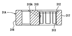
- the pipe connection device of the second embodiment is characterized by a drainage passage 315A formed in the female block member 31A.
- the drainage passage 315A is a passage formed so as to communicate the internal passage located inside the small-diameter hole 313 and the other outer surface 316. Therefore, the drainage passage 315A is a passage formed so as to communicate a part of the outer peripheral surface of the first pipe 34 with the other outer surface 316 of the female block member 31A at a portion in contact with the small diameter hole portion 313. is there.
- the drainage passage 315A is also a tunnel-like passage that penetrates the female block member 31A from the small-diameter hole 313 to the other outer surface 316.
- the water that has entered the inner surface of the small-diameter hole 313 reaches the other outer surface 316 through the drainage passage 315A and can be discharged to the outside.
- a predetermined shape is provided in advance in the small-diameter hole 313 of the female block member 31 ⁇ / b> A in order to caulk and fix the first pipe 34.
- the drainage passage 315A may be provided at an arbitrary place in the female block member 31A, as in the first embodiment.
- the drainage passages 315 and 315A disclosed in the first embodiment and the second embodiment are provided in any place in the female block members 31 and 31A regardless of the above-described areas. This form will be described with reference to FIGS. Hereinafter, configurations, operations, and the like different from the above-described embodiments will be described. Therefore, configurations, operations, and the like that are not particularly described are the same as those in the above embodiments.
- the drainage passage 415 has a passage cross-sectional area, for example, a lower limit value of the passage diameter, determined according to the position of the female block member 41.
- the passage cross-sectional area of the drainage passage 415 is based on the position of the drainage passage 415 that angularly displaces around the axis of the first pipe 34 starting from the thinnest portion of the female block member 41. Is set. The characteristics of the drainage passage 415 are obtained based on the following verification.
- the heat pump cycle device 100A has a passage formed in an annular shape by pipe connection of the compressor 20, the high pressure side heat exchanger 17A, the expansion valve 25, the low pressure side heat exchanger 4A, and the accumulator tank 26. Furthermore, the heat pump cycle device 100A is provided with an electromagnetic valve 19 that opens and closes a bypass passage that connects the upstream portion and the downstream portion of the expansion valve 25.
- the expansion valve 25, the low-pressure side heat exchanger 4A, the accumulator tank 26, and the electromagnetic valve 19 were tested in a state where they were accommodated in the same tank 27.
- the positions where the pipe connection devices are installed are a portion near the inlet and a portion near the outlet of the accumulator tank 26. That is, the pipe connection device is installed at least between the low pressure side heat exchanger 4 ⁇ / b> A and the accumulator tank 26 and between the accumulator tank 26 and the compressor 20.
- the above-mentioned inside of the tank 27 was set to 25 ° C. and a humidity of 90%, and water was sufficiently adhered to the pipe connection device in advance.
- the heat pump operation and the defrosting operation are alternately controlled about 20,000 times while controlling the pipe temperature so as to fluctuate in the range of about ⁇ 15 ° C. to about 15 ° C.
- visual evaluation was performed.
- the heat pump operation is an operation in which the compressor 20 is operated by controlling the solenoid valve 19 so that the bypass passage is closed.
- the defrosting operation is an operation of operating the compressor 20 by controlling the electromagnetic valve 19 so that the bypass passage is fully opened.
- the visual evaluation for example, when abnormal deformation occurs in the female block member 41, it is determined as rejected.
- nitrogen gas etc. were inject
- the determination result is as shown in FIG.
- the circle shown in FIG. 10 is a pass determination, and the cross is a fail determination.
- a solid line shown in FIG. 10 can be drawn at the boundary between the circle and the cross.
- the lower limit line of the passage cross-sectional area corresponding to the boundary of the failure evaluation.
- the passage cross-sectional area of the drainage passage 415 can be reduced in a portion thicker than a thin portion.
- the lower limit line of the passage cross-sectional area seems to exist due to the balance between the drainage speed and the water expansion speed due to freezing. Moreover, since the pressure of the water at the time of draining the drainage passage 415 is relatively higher as the angle ⁇ is smaller, it is necessary to increase the drainage speed. In order to increase the drainage speed, it is preferable that the pressure loss during drainage is low. Therefore, it is considered that the lower limit line of the passage cross-sectional area becomes larger as the angle ⁇ is smaller.
- the drainage passage 415 can grasp the lower limit value of the passage cross-sectional area that exhibits the effect according to the position as described above, it is possible to avoid setting a large drainage passage carelessly. Therefore, since a passage cross-sectional area that can be predicted to exhibit the effect can be set, it is possible to provide a pipe connection device that prevents a decrease in strength and sealing performance.
- the drainage passage 415 can be replaced with the drainage passage 315 of the first embodiment. That is, the female block member 41 may be configured by a groove portion formed continuously on the end surface 410 from the large-diameter hole portion 312 to one outer surface 417 or the other outer surface 416.
- the passage cross-sectional area of the drainage passage 415 changes from the inner surface side to the outer surface side of the female block member 41
- the passage cross-section here is applied to the smallest passage cross-sectional area in the drainage passage. It shall be. That is, in the case of a passage where the passage cross-sectional area is not constant, the passage cross-sectional area of the smallest portion is set to be equal to or more than the above lower limit line.
- the through hole 414 for passing a bolt is the above-described through hole 314, the large-diameter hole portion 412 is the above-described large-diameter hole portion 312, and the small-diameter hole portion 413 is the above-described small-diameter hole portion 313.
- a pipe connection device which is another form of the first embodiment will be described with reference to FIG.
- the constituent elements denoted by the same reference numerals as those of the drawings referred to in the first embodiment are the same elements, and the operational effects thereof are also the same.
- different forms, processing procedures, operations, and the like from the first embodiment will be described.
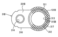
- the pipe connection device of the fourth embodiment is characterized by the material constituting the female block member 31B.
- the female block member 31B is composed of a plurality of different materials, and the material differs depending on the part.
- the area 131B shown by the shaded portion in FIG. 12 is set as a portion having a large heat capacity, and the area 231B set around the through hole 314 other than the area 131B has a smaller heat capacity than the area 131B and is drained. This is a portion where the passage 315B is not provided.
- the area 131B is formed of a resin material
- the area 231B is formed of a metal material having a smaller heat capacity than the resin.
- female side block member 31B is provided with drainage passage 315B in area 131B with a larger heat capacity than other parts.
- the drainage passage 315 ⁇ / b> B is a passage that allows the internal passage located inside the large-diameter hole portion 312 or the small-diameter hole portion 313 to communicate with one outer surface 317.
- the drainage passage 515 is provided at an arbitrary place of the female block member 51 regardless of the above-described area with respect to the female block member 31B disclosed in the fourth embodiment. Will be described with reference to FIGS. 13 and 14.
- FIG. Hereinafter, configurations and operations different from those of the above embodiment will be described. Therefore, configurations, operations, and the like that are not particularly described are the same as those in the above embodiment.
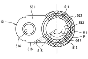
- the female block member 51 is characterized by the material constituting the female block member 51, similar to the female block member 31 ⁇ / b> B.
- the female block member 51 is composed of a plurality of different materials, and the material differs depending on the part.
- an area 532 indicated by a shaded portion in FIG. 13 is set as a portion having a large heat capacity, and an area 531 set around the through hole 514 other than the area 532 has a smaller heat capacity than the area 532.
- the drainage passage 515 has a passage cross-sectional area, for example, a lower limit value of the passage diameter, determined according to the position of the female block member 51.
- the passage cross-sectional area of the drainage passage 515 is based on the position of the drainage passage 515 that is angularly displaced about the axis of the first pipe 34 with the thinnest portion of the female block member 51 as the starting position. Is set.
- the features of the drainage passage 515 are obtained based on verification based on tests and evaluations similar to those of the third embodiment.
- the determination result is as shown in FIG.
- the circle shown in FIG. 14 is a pass determination, and the cross is a fail determination.
- a solid line shown in FIG. 14 can be drawn at the boundary between the circle and the cross.
- This solid line is the lower limit line of the passage cross-sectional area corresponding to the boundary between the pass evaluation and the fail evaluation.
- the lower limit line has a constant value in the range of ⁇ corresponding to the area 532 from 0 ° to ⁇ 1. Further, when the lower limit line exceeds ⁇ 1, the lower limit line becomes a value larger than the predetermined value, and decreases as ⁇ increases therefrom. Therefore, the lower limit line is a small constant value in the area 532, is larger than the value in the area 532 in the area 531, and decreases as ⁇ increases.
- the passage cross-sectional area of the drainage passage 515 can be set in a range above the characteristic line shown in FIG. That is, the drainage passage 515 can be set to any value as long as it is a passage diameter included in the range above the characteristic line in FIG. 14. If the drainage passage 515 is set in this way, The above-described freezing suppression effect is exhibited.
- ⁇ can be set to an arbitrary angle in the range of 0 ° to 180 °.
- the drainage passage 515 can grasp the lower limit value of the passage cross-sectional area that exerts the effect according to the position as described above, it is possible to avoid inadvertently setting a large drainage passage. Therefore, since a passage cross-sectional area that can be predicted to exhibit the effect can be set, it is possible to provide a pipe connection device that prevents a decrease in strength and sealing performance.
- the drainage passage 515 can be replaced with the drainage passage 315B of the fourth embodiment. That is, the female block member 51 may be configured by a groove portion formed continuously on the end surface from the large-diameter hole portion 512 to one outer surface 517 or the other outer surface 516.
- the tip hole portion 511 corresponds to the tip hole portion 311 described above
- the small diameter hole portion 513 corresponds to the aforementioned small diameter hole portion 313.
- the drainage passage is a passage formed in advance in the female block member 31 before the female block member 31 and the male block member 32 are assembled, and is also present in the resultant product after assembly. It is a passage to do.
- the drainage passage is not limited to the one described in the above embodiment. For example, when the female block member 31 and the male block member 32 are not formed in advance, the female block member 31 and the like are intentionally deformed to fix the result. It may be a passage formed.
- the heat pump cycle device 100 described in the first embodiment is merely an example, and the heat pump cycle device to which the pipe connection device of the present disclosure can be applied is not limited to the configuration and operation disclosed in the first embodiment. Absent.
- the male protrusion 322 provided on the male block member 32 is a part of a solid part forming the male block member 32 and is formed into a cylindrical shape integrally with the end surface 320.
- the present invention is not limited to such a form.
- the male-side protrusion provided on the male-side block member 32 may be configured by a tip portion of the second pipe 33 that is formed integrally with the second pipe 33. That is, the second pipe 33 is fixed to the male block member 32 in a state in which the distal end portion protrudes from the end surface 320 in a shape like a male protrusion.
- a means for heating the female block member and the like may be further provided to freeze the freeze.
Landscapes
- Engineering & Computer Science (AREA)
- General Engineering & Computer Science (AREA)
- Mechanical Engineering (AREA)
- Physics & Mathematics (AREA)
- Thermal Sciences (AREA)
- Air-Conditioning For Vehicles (AREA)
- Flanged Joints, Insulating Joints, And Other Joints (AREA)
- Joints With Pressure Members (AREA)
Abstract
Priority Applications (3)
| Application Number | Priority Date | Filing Date | Title |
|---|---|---|---|
| US14/408,896 US9568128B2 (en) | 2012-06-22 | 2013-06-11 | Piping connection device and heat pump cycle device having same |
| DE112013003101.9T DE112013003101T5 (de) | 2012-06-22 | 2013-06-11 | Verbindungsvorrichtung für Rohrleitungen und Wärmepumpenkreislaufvorrichtung, welche dieselbige aufweist |
| CN201380032186.2A CN104395664B (zh) | 2012-06-22 | 2013-06-11 | 配管连接装置及具有该配管连接装置的热泵循环装置 |
Applications Claiming Priority (4)
| Application Number | Priority Date | Filing Date | Title |
|---|---|---|---|
| JP2012-141197 | 2012-06-22 | ||
| JP2012141197 | 2012-06-22 | ||
| JP2013-110165 | 2013-05-24 | ||
| JP2013110165A JP6056657B2 (ja) | 2012-06-22 | 2013-05-24 | 配管接続装置及びこれを有するヒートポンプサイクル装置 |
Publications (1)
| Publication Number | Publication Date |
|---|---|
| WO2013190803A1 true WO2013190803A1 (fr) | 2013-12-27 |
Family
ID=49768418
Family Applications (1)
| Application Number | Title | Priority Date | Filing Date |
|---|---|---|---|
| PCT/JP2013/003658 Ceased WO2013190803A1 (fr) | 2012-06-22 | 2013-06-11 | Dispositif de raccordement de tuyauterie et dispositif de cycle de pompe à chaleur qui comprend ce dernier |
Country Status (5)
| Country | Link |
|---|---|
| US (1) | US9568128B2 (fr) |
| JP (1) | JP6056657B2 (fr) |
| CN (1) | CN104395664B (fr) |
| DE (1) | DE112013003101T5 (fr) |
| WO (1) | WO2013190803A1 (fr) |
Cited By (3)
| Publication number | Priority date | Publication date | Assignee | Title |
|---|---|---|---|---|
| US10378686B2 (en) * | 2016-07-08 | 2019-08-13 | Hanon Systems | Plastic seal fitting |
| US11001126B2 (en) * | 2016-03-22 | 2021-05-11 | Denso Corporation | Vehicle air-conditioning unit |
| CN116240956A (zh) * | 2023-04-10 | 2023-06-09 | 江苏力达自动化设备有限公司 | 可调式箱式无负压供水设备 |
Families Citing this family (7)
| Publication number | Priority date | Publication date | Assignee | Title |
|---|---|---|---|---|
| WO2016185243A1 (fr) * | 2015-05-15 | 2016-11-24 | Carrier Corporation | Système d'expansion à étages |
| DE202016100195U1 (de) * | 2016-01-15 | 2016-02-01 | Ti Automotive Engineering Centre (Heidelberg) Gmbh | Verbindungsanordnung für eine Klimaanlage |
| DE102016206459B3 (de) * | 2016-04-18 | 2017-10-05 | Continental Automotive Gmbh | Kombination, umfassend ein Gehäuse und einen Flansch, und Anordnung |
| US20220235891A1 (en) * | 2021-01-25 | 2022-07-28 | Hutchinson Fluid Management Systems, Inc. | Dual plane seal air conditioner connector |
| FR3124567B1 (fr) * | 2021-06-25 | 2026-02-06 | Hutchinson | Dispositif de raccordement fluidique et vanne inserable anti-retour pour vehicule |
| CN116105940B (zh) * | 2022-07-04 | 2025-07-29 | 浙江中骐科技有限公司 | 热管理集成模块智能生产线 |
| US12311729B2 (en) * | 2022-07-04 | 2025-05-27 | ZHEJIANG ZOCH TECHNOLOGY Co. Ltd. | Apparatus for assembling a heat pump |
Citations (4)
| Publication number | Priority date | Publication date | Assignee | Title |
|---|---|---|---|---|
| JP2001004251A (ja) * | 1999-04-22 | 2001-01-12 | Denso Corp | 冷凍機用漏洩防止装置 |
| JP2005042815A (ja) * | 2003-07-22 | 2005-02-17 | Denso Corp | 冷凍サイクル用配管継手 |
| JP2005147320A (ja) * | 2003-11-18 | 2005-06-09 | Nissan Motor Co Ltd | 配管接続構造および配管取付用コネクタ |
| WO2007015434A1 (fr) * | 2005-08-03 | 2007-02-08 | Eagle Industry Co., Ltd. | Raccord pour tube |
Family Cites Families (11)
| Publication number | Priority date | Publication date | Assignee | Title |
|---|---|---|---|---|
| DE1525925A1 (de) * | 1966-09-16 | 1970-01-22 | Vickers Zimmer Ag | Flanschverbindung,insbesondere fuer Doppelrohrleitungen |
| US3948315A (en) * | 1974-08-13 | 1976-04-06 | Brown Fintube Company | Closure for heat exchanger |
| JP3170840B2 (ja) * | 1992-01-31 | 2001-05-28 | 日産自動車株式会社 | パイプ取付構造 |
| DE19817331A1 (de) * | 1998-04-18 | 1999-10-21 | Karl Hiestand | Druckmittelzuführungseinrichtung |
| US6443502B1 (en) | 1999-04-22 | 2002-09-03 | Denso Corporation | Leakage restriction device for refrigeration cycle |
| US6908117B1 (en) * | 2000-10-06 | 2005-06-21 | Hutchinson Fts, Inc. | Block-conduit connection alignment device |
| ES2263857T3 (es) * | 2003-02-05 | 2006-12-16 | CONTITECH KUHNER GMBH & CIE. KG | Disposicion de union para tuberias de agente frigorifico. |
| NL1025631C2 (nl) * | 2004-03-03 | 2005-09-08 | Berkin Bv | Afdichtingsamenstel. |
| US7971910B2 (en) * | 2006-11-30 | 2011-07-05 | Ford Motor Company | Conduit to component fitting having a leak detection mechanism |
| JP2009257743A (ja) | 2008-03-25 | 2009-11-05 | Daikin Ind Ltd | 冷凍装置 |
| JP5619526B2 (ja) | 2010-08-25 | 2014-11-05 | 株式会社不二工機 | 電磁弁一体型膨張弁 |
-
2013
- 2013-05-24 JP JP2013110165A patent/JP6056657B2/ja not_active Expired - Fee Related
- 2013-06-11 US US14/408,896 patent/US9568128B2/en not_active Expired - Fee Related
- 2013-06-11 WO PCT/JP2013/003658 patent/WO2013190803A1/fr not_active Ceased
- 2013-06-11 CN CN201380032186.2A patent/CN104395664B/zh not_active Expired - Fee Related
- 2013-06-11 DE DE112013003101.9T patent/DE112013003101T5/de not_active Withdrawn
Patent Citations (4)
| Publication number | Priority date | Publication date | Assignee | Title |
|---|---|---|---|---|
| JP2001004251A (ja) * | 1999-04-22 | 2001-01-12 | Denso Corp | 冷凍機用漏洩防止装置 |
| JP2005042815A (ja) * | 2003-07-22 | 2005-02-17 | Denso Corp | 冷凍サイクル用配管継手 |
| JP2005147320A (ja) * | 2003-11-18 | 2005-06-09 | Nissan Motor Co Ltd | 配管接続構造および配管取付用コネクタ |
| WO2007015434A1 (fr) * | 2005-08-03 | 2007-02-08 | Eagle Industry Co., Ltd. | Raccord pour tube |
Cited By (4)
| Publication number | Priority date | Publication date | Assignee | Title |
|---|---|---|---|---|
| US11001126B2 (en) * | 2016-03-22 | 2021-05-11 | Denso Corporation | Vehicle air-conditioning unit |
| US10378686B2 (en) * | 2016-07-08 | 2019-08-13 | Hanon Systems | Plastic seal fitting |
| CN116240956A (zh) * | 2023-04-10 | 2023-06-09 | 江苏力达自动化设备有限公司 | 可调式箱式无负压供水设备 |
| CN116240956B (zh) * | 2023-04-10 | 2024-02-20 | 江苏力达自动化设备有限公司 | 可调式箱式无负压供水设备 |
Also Published As
| Publication number | Publication date |
|---|---|
| JP2014025579A (ja) | 2014-02-06 |
| DE112013003101T5 (de) | 2015-04-02 |
| JP6056657B2 (ja) | 2017-01-11 |
| CN104395664A (zh) | 2015-03-04 |
| US9568128B2 (en) | 2017-02-14 |
| CN104395664B (zh) | 2016-03-02 |
| US20150300544A1 (en) | 2015-10-22 |
Similar Documents
| Publication | Publication Date | Title |
|---|---|---|
| JP6056657B2 (ja) | 配管接続装置及びこれを有するヒートポンプサイクル装置 | |
| JP6141744B2 (ja) | 冷凍サイクル装置 | |
| JP6909889B2 (ja) | 電気自動車用ヒートポンプシステム及びその制御方法 | |
| JP5983335B2 (ja) | 熱交換器 | |
| KR100332532B1 (ko) | 공기조화기 | |
| US8413456B2 (en) | Refrigeration apparatus | |
| EP3252402B1 (fr) | Pompe à chaleur | |
| JP2008121985A (ja) | 熱交換システム | |
| US20080202156A1 (en) | Air-conditioning system for vehicles | |
| JP2012007821A (ja) | 熱交換器 | |
| CN102109202A (zh) | 空气调节器 | |
| CN105698424A (zh) | 一种超低温制冷的单冷分体式空调器及其超低温制冷方法 | |
| JP2006170500A (ja) | 空気調和装置およびその運転方法 | |
| KR100253417B1 (ko) | 카에어컨 | |
| JP4265677B2 (ja) | エジェクタ式冷凍サイクル用ユニット | |
| JP4462435B2 (ja) | 冷凍装置 | |
| US9228762B2 (en) | Refrigeration system having dual suction port compressor | |
| CN115143555A (zh) | 空调系统 | |
| JP2010052478A (ja) | 車両用空気調和装置 | |
| KR101060614B1 (ko) | 자동차용 에어컨 시스템 | |
| JP2009204183A (ja) | 冷凍サイクル装置 | |
| JP2007107853A (ja) | 空気調和装置 | |
| JP4513896B2 (ja) | エジェクタおよびエジェクタの製造方法 | |
| JPH08271102A (ja) | 冷凍装置 | |
| JP2006242443A (ja) | 空気調和装置 |
Legal Events
| Date | Code | Title | Description |
|---|---|---|---|
| 121 | Ep: the epo has been informed by wipo that ep was designated in this application |
Ref document number: 13806682 Country of ref document: EP Kind code of ref document: A1 |
|
| WWE | Wipo information: entry into national phase |
Ref document number: 14408896 Country of ref document: US |
|
| WWE | Wipo information: entry into national phase |
Ref document number: 112013003101 Country of ref document: DE Ref document number: 1120130031019 Country of ref document: DE |
|
| 122 | Ep: pct application non-entry in european phase |
Ref document number: 13806682 Country of ref document: EP Kind code of ref document: A1 |