WO2013190816A1 - 洗濯機および洗濯機制御システム - Google Patents
洗濯機および洗濯機制御システム Download PDFInfo
- Publication number
- WO2013190816A1 WO2013190816A1 PCT/JP2013/003757 JP2013003757W WO2013190816A1 WO 2013190816 A1 WO2013190816 A1 WO 2013190816A1 JP 2013003757 W JP2013003757 W JP 2013003757W WO 2013190816 A1 WO2013190816 A1 WO 2013190816A1
- Authority
- WO
- WIPO (PCT)
- Prior art keywords
- washing machine
- unit
- display unit
- power
- course
- Prior art date
- Legal status (The legal status is an assumption and is not a legal conclusion. Google has not performed a legal analysis and makes no representation as to the accuracy of the status listed.)
- Ceased
Links
Images


Classifications
-
- D—TEXTILES; PAPER
- D06—TREATMENT OF TEXTILES OR THE LIKE; LAUNDERING; FLEXIBLE MATERIALS NOT OTHERWISE PROVIDED FOR
- D06F—LAUNDERING, DRYING, IRONING, PRESSING OR FOLDING TEXTILE ARTICLES
- D06F34/00—Details of control systems for washing machines, washer-dryers or laundry dryers
- D06F34/28—Arrangements for program selection, e.g. control panels therefor; Arrangements for indicating program parameters, e.g. the selected program or its progress
-
- G—PHYSICS
- G08—SIGNALLING
- G08C—TRANSMISSION SYSTEMS FOR MEASURED VALUES, CONTROL OR SIMILAR SIGNALS
- G08C17/00—Arrangements for transmitting signals characterised by the use of a wireless electrical link
- G08C17/02—Arrangements for transmitting signals characterised by the use of a wireless electrical link using a radio link
-
- D—TEXTILES; PAPER
- D06—TREATMENT OF TEXTILES OR THE LIKE; LAUNDERING; FLEXIBLE MATERIALS NOT OTHERWISE PROVIDED FOR
- D06F—LAUNDERING, DRYING, IRONING, PRESSING OR FOLDING TEXTILE ARTICLES
- D06F34/00—Details of control systems for washing machines, washer-dryers or laundry dryers
- D06F34/14—Arrangements for detecting or measuring specific parameters
-
- D—TEXTILES; PAPER
- D06—TREATMENT OF TEXTILES OR THE LIKE; LAUNDERING; FLEXIBLE MATERIALS NOT OTHERWISE PROVIDED FOR
- D06F—LAUNDERING, DRYING, IRONING, PRESSING OR FOLDING TEXTILE ARTICLES
- D06F39/00—Details of washing machines not specific to a single type of machines covered by groups D06F9/00 - D06F27/00
- D06F39/12—Casings; Tubs
-
- G—PHYSICS
- G08—SIGNALLING
- G08C—TRANSMISSION SYSTEMS FOR MEASURED VALUES, CONTROL OR SIMILAR SIGNALS
- G08C2201/00—Transmission systems of control signals via wireless link
- G08C2201/50—Receiving or transmitting feedback, e.g. replies, status updates, acknowledgements, from the controlled devices
Definitions
- the present invention relates to a washing machine for washing clothes put in a washing and dewatering tub, and a washing machine control system for controlling the washing machine.
- FIG. 9 is a cross-sectional view seen from the side showing the configuration of the conventional washing machine 101
- FIG. 10 is a circuit block diagram of the washing machine 101
- FIG. 11 shows the operation unit 102 of the washing machine 101. It is a figure which shows a structure.
- the washing machine 101 includes a housing 103 configured substantially in a rectangular parallelepiped shape. Inside the housing 103, a water receiving tank 104 configured in a substantially cylindrical shape is suspended by a suspension bar 105. In the water receiving tub 104, a washing and dewatering tub 106 having a substantially cylindrical shape is rotatably included. A stirring blade 107 is provided at the bottom of the washing and dewatering tank 106 so as to be rotatable about an axis along the vertical direction.
- a motor 108 for rotating the stirring blade 107 is provided on the outer bottom of the water receiving tank 104.
- the motor 108 is constituted by a direct current brushless motor.
- a power switching mechanism 109 is provided between the motor 108 and the stirring blade 107. The power switching mechanism 109 decelerates the driving force from the motor 108 during washing and transmits it to the stirring blade 107, and transmits the driving force from the motor 108 to the stirring blade 107 one-on-one during dehydration.
- a cover body 110 that constitutes a sprinkling part for watering is provided on the water receiving tank 104.
- a water supply valve 111 for supplying water into the washing and dewatering tub 106 is provided above the housing 103.
- a drain valve 112 for draining the washing water in the water receiving tank 104 is provided below the water receiving tank 104.
- a connecting portion 113 is provided at the lower part of the outer wall of the water receiving tank 104.
- a water level detector 114 that detects the water level of the water receiving tank 104 is connected to the connection unit 113.
- the water level detector 114 is configured to convert the water pressure at the connection portion 113 into an electrical frequency.
- an operation unit 102 is disposed on the front upper surface of the washing machine 101. Selection of a mode such as a driving course and various functions is performed by a user inputting to the input unit 126 of the operation unit 102.
- the control unit 122 provided inside the front upper surface of the washing machine 101 displays on the display unit 127 of the operation unit 102 based on the input information to notify the user.
- the motor 108 is driven by the inverter circuit 115.
- the inverter circuit 115 has six switching elements 116A to 116F. Each of the switching elements 116A to 116F has a parallel circuit composed of a power transistor and a reverse conducting diode.
- the power source 117 supplies a voltage to the inverter circuit 115 through a DC power source conversion device including a diode bridge 118, a choke coil 119, and a smoothing capacitor 120.
- the power source 117 also supplies a voltage to the pump 160, the water supply valve 111, the drain valve 112, and the power switching mechanism 109.
- the motor 108 is provided with three position detectors 121.
- the position detector 121 detects the rotational position of the motor 108.
- the control unit 122 has a rotation control unit 123.
- the rotation control unit 123 controls the drive circuit 124 based on the rotation position of the motor 108 detected by the position detector 121 and the water level of the water receiving tank 104 detected by the water level detector 114.
- the drive circuit 124 drives the inverter circuit 115 based on an instruction from the rotation control unit 123.
- the pump 160, the water supply valve 111, the drain valve 112, and the power switching mechanism 109 are connected to the load driving unit 125.
- the load driving unit 125 drives the pump 160, the water supply valve 111, the drain valve 112, and the power switching mechanism 109 based on an instruction from the control unit 122.
- the operation unit 102 includes an input unit 126 for inputting the washing time, the number of times of rinsing, and the dehydration time, and a display unit 127 for displaying the washing time, the number of times of rinsing, the dehydration time, and the like input to the input unit 126.
- an input unit 126 for inputting the washing time, the number of times of rinsing, and the dehydration time
- a display unit 127 for displaying the washing time, the number of times of rinsing, the dehydration time, and the like input to the input unit 126.
- the input unit 126 includes a washing time setting switch 126a for setting a washing time, a rinsing frequency setting switch 126b for setting a rinsing frequency, a dehydration time setting switch 126c for setting a dehydration time, and a drying time.
- a drying time setting switch 126d has a drying time setting switch 126d.
- the input unit 126 includes a start / pause switch 126e, a power-on switch 126f, a power-off switch 126g, and the like.
- the display unit 127 includes a washing time display unit 127a, a rinse count display unit 127b, a dehydration time display unit 127c, a drying time display unit 127d, and the like.
- the input unit 126 includes a driving course selection switch 126h that selects any one of a plurality of basic driving courses and special driving courses, and a plurality of driving courses corresponding to each of the plurality of basic driving courses and special driving courses. And a selection display portion 127e.
- the special operation course is set by changing at least one of the washing time, the number of times of rinsing, and the dehydrating time by input to the input unit 126.
- the plurality of driving course selection display units 127e are each configured by a light emitting diode.
- the basic driving course includes, for example, an “automatic course”, a “hurry course”, and a “home cleaning course”. “Omakase Course” is the most standard driving course. For example, the washing time is set to “9 minutes”, the number of times of rinsing is set to “twice water injection”, and the dehydration time is set to “7 minutes”. ing.
- the “hurry course” is a basic operation course for washing in a hurry.
- the washing time is set to “3 minutes”
- the number of rinsings is set to “1 water injection”
- the dehydration time is “3 minutes”. "Is set.
- the “house cleaning course” is a basic operation course for washing clothes recommended for dry cleaning with the washing machine 101 in the home.
- the washing time is set to “12 minutes” and the number of times of rinsing is “ “Twice” is set, and the dehydration time is set to “40 seconds”.
- the driving course selection display section 127e is provided for each of the “automatic course”, “hurry course”, “house cleaning course”, and “special driving course”. Every time the driving course selection switch 126h is pressed, the driving course selection display section 127e is switched in order of “automatic course”, “hurry course”, “home cleaning course”, and “special driving course”, and lights up.
- the washing time, the number of times of rinsing, and the dehydrating time specified in advance in the “automatic course” that is the most standard driving course are selected.
- the washing time display portion 127a, the rinse count display portion 127b, and the dehydration time display portion 127c are displayed on the washing time display portion 127a, the rinse count display portion 127b, and the dehydration time display portion 127c, respectively.
- the user then performs his / her own washing while referring to the washing time, the number of times of rinsing, and the dehydrating time of the “Omakase Course” displayed on the washing time display portion 127a, the rinse count display portion 127b, and the dehydration time display portion 127c.
- the washing time setting switch 126a the rinsing number setting switch 126b, and the dehydration time setting switch 126c is pressed a desired number of times.
- the user can set a special operation course by changing at least one of the washing time, the number of times of rinsing, and the dehydration time of the “Random Course”.
- control unit 122 performs a series of steps of washing, rinsing, and dehydration based on the conditions of the “special operation course” set by the input unit 126, and the drive circuit 124 and the load driving unit 125. To control.
- ⁇ Provides a washing machine with excellent operability and a washing machine control system that can set a washing machine operation course from a remote location.
- the washing machine performs wireless communication with the terminal device.
- the washing machine includes a control unit that controls the operation and communication of the washing machine, and an operation display unit that is arranged in the left-right direction above the washing machine and sets and displays an operation course.
- the operation display unit includes a power-on switch for turning on the power, a display unit for displaying setting details of the driving course, and a washing machine transmission / reception unit for communicating with the terminal device.
- the control unit receives the driving course information transmitted from the terminal device by the washing machine transmission / reception unit, and displays the driving course and controls the driving based on the driving course information.
- the power-on switch is disposed on either the left or right side of the operation display unit, and the washing machine transmission / reception unit is disposed on the left or right side of the operation display unit on the opposite side to the position where the power-on switch is disposed. ing.
- the washing machine control system includes a terminal device and a washing machine that performs wireless communication with the terminal device.
- the washing machine includes a control unit that controls the operation and communication of the washing machine, and an operation display unit that is arranged in the left-right direction above the washing machine and sets and displays an operation course.
- the operation display unit includes a power-on switch that turns on the power, a display unit that displays the setting content of the driving course, and a washing machine transmission / reception unit that communicates with the terminal device.
- the terminal device has a terminal transmission / reception unit that communicates with the washing machine.
- the control unit of the washing machine receives the driving course information transmitted from the terminal transmission / reception unit of the terminal device, and displays the driving course and controls driving based on the driving course information.
- the power-on switch is arranged on either the left or right side of the operation display unit, and the washing machine transmission / reception unit is arranged on the left or right side of the operation display unit on the side opposite to the position where the power-on switch is arranged.
- FIG. 1 is a perspective view showing the configuration of the washing machine control system according to the first embodiment of the present invention.
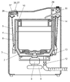
- FIG. 2 is a cross-sectional view of the washing machine of the washing machine control system according to the first embodiment of the present invention as seen from the side.
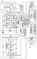
- FIG. 3 is a circuit block diagram of the washing machine control system according to the first embodiment of the present invention.
- FIG. 4 is a diagram showing an operation display unit of the washing machine in the washing machine control system according to the first embodiment of the present invention.
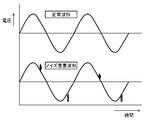
- FIG. 5 is a diagram showing a normal waveform of a power supply voltage and a noise superimposed waveform in the first embodiment of the present invention.
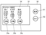
- FIG. 6A is a diagram illustrating a terminal operation unit of the terminal device of the washing machine control system according to the first embodiment of the present invention.
- FIG. 6B is a diagram illustrating a terminal operation unit for explaining a procedure of transferring the net course setting content of the terminal device of the washing machine control system according to the first embodiment of the present invention.
- FIG. 7 is a flowchart showing the operation of the washing machine control system in the embodiment of the present invention.
- FIG. 8 is a perspective view of a drum-type washing machine according to the second embodiment of the present invention.
- FIG. 9 is a cross-sectional view seen from the side showing the configuration of a conventional washing machine.
- FIG. 10 is a circuit block diagram of a conventional washing machine.
- FIG. 11 is a diagram illustrating a configuration of an operation unit of a conventional washing machine.
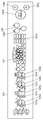
- FIG. 1 is a perspective view showing the configuration of the washing machine control system 50 according to the first embodiment of the present invention
- FIG. 2 is a sectional view of the washing machine 29 of the washing machine control system 50 as viewed from the side.
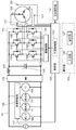
- FIG. 3 is a circuit block diagram of the washing machine control system 50.
- the washing machine 29 and the terminal device 28 are connected by wireless communication.
- the user can control the washing machine 29 while confirming the setting contents on the display unit 27 by operating the input unit 26 of the operation display unit 37 of the washing machine 29.
- the user can also operate the terminal device 28 to control the washing machine 29. Therefore, the terminal device 28 has a terminal transmission / reception unit 33 that exchanges information with the washing machine 29.
- the operation display unit 37 of the washing machine 29 includes a washing machine transmission / reception unit 38 that exchanges information with the terminal device 28.
- the washing machine 29 includes a housing 3 configured substantially in a rectangular parallelepiped.
- a water receiving tank 4 configured substantially in a cylindrical shape is suspended inside a housing 3 by a suspension bar 5.
- a washing and dewatering tub 6 having a substantially cylindrical shape is rotatably included in the water receiving tub 4, a washing and dewatering tub 6 having a substantially cylindrical shape is rotatably included in the water receiving tub 4, a washing and dewatering tub 6 having a substantially cylindrical shape is rotatably included.
- a stirring blade 7 is provided at the bottom of the washing and dewatering tub 6 so as to be rotatable about an axis along the vertical direction.
- a motor 8 for rotating the stirring blade 7 is provided on the outer bottom of the water receiving tank 4.
- the motor 8 is configured by a direct current brushless motor.
- a power switching mechanism 9 is provided between the motor 8 and the stirring blade 7. The power switching mechanism 9 decelerates the driving force from the motor 8 during washing and transmits it to the stirring blade 7, and transmits the driving force from the motor 8 to the stirring blade 7 one-on-one during dehydration.
- a cover body 10 that constitutes a sprinkling discharge section is provided on the water receiving tank 4.
- a water supply valve 11 for supplying water into the washing and dewatering tub 6 is provided above the housing 3.
- a drain valve 12 for draining the washing water in the water receiving tank 4 is provided below the water receiving tank 4.
- a connecting portion 13 is provided at the lower part of the outer wall of the water receiving tank 4.
- a water level detector 14 that detects the water level of the water receiving tank 4 is connected to the connecting portion 13.
- the water level detector 14 is configured to convert the water pressure at the connection portion 13 into an electrical frequency.
- the mode such as the driving course and various functions are selected when the user inputs to the input unit 26. Based on the input information, display is performed on the display unit 27 to notify the user.
- the operation display unit 37 is disposed on the front upper surface of the washing machine 29 and has a shape extending in the left-right direction.
- the operation display unit 37 is provided on an inclined surface on the front upper surface of the washing machine 29.
- a control unit 39 that controls the washing machine is disposed inside the front upper surface of the washing machine 29.
- the terminal transmission / reception part 33 protruded from the terminal device 28 was shown in FIG. 1, it is not limited to such a shape.
- the terminal transmission / reception unit 33 may be built in the terminal device 28.
- the inverter circuit 15 has six switching elements 16A to 16F. Each of the switching elements 16A to 16F has a parallel circuit composed of a power transistor and a reverse conducting diode.
- the power source 17 supplies a voltage to the inverter circuit 15 through a DC power source conversion device including a diode bridge 18, a choke coil 19, and a smoothing capacitor 20.
- the power source 17 also supplies voltage to the pump 60, the water supply valve 11, the drain valve 12, and the power switching mechanism 9.
- the motor 8 is provided with three position detectors 21.
- the position detector 21 detects the rotational position of the motor 8.
- the control unit 39 has a rotation control unit 23.
- the rotation control unit 23 controls the drive circuit 24 based on the rotation position of the motor 8 detected by the position detector 21 and the water level of the water receiving tank 4 detected by the water level detector 14.
- the drive circuit 24 drives the inverter circuit 15 based on an instruction from the rotation control unit 23.
- the pump 60, the water supply valve 11, the drain valve 12, and the power switching mechanism 9 are connected to the load driving unit 25.
- the load drive unit 25 drives the pump 60, the water supply valve 11, the drain valve 12, and the power switching mechanism 9 based on an instruction from the control unit 39.
- the operation display unit 37 includes an input unit 26 for inputting the washing time, the number of times of rinsing, and the dehydration time, and the display unit 27 for displaying the washing time, the number of times of rinsing, the dehydration time, and the like input to the input unit 26. have.
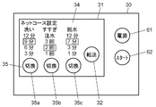
- the terminal device 28 includes a terminal operation unit 30.
- the terminal operation unit 30 includes a net course setting unit 31 and a transfer start button 32.
- the net course setting unit 31 sets the contents of the net course executed by the washing machine 29 by changing the contents of at least one of the series of washing, rinsing, and dehydration processes from the basic operation course.
- the terminal transmission / reception unit 33 transmits information representing the contents of the net course set by the net course setting unit 31 to the washing machine 29 by wireless communication.
- a wireless communication method NFC (which has been recently used in mobile phones and the like, which has a power supply for supplying voltage to the terminal operation unit 30 and the terminal transmission / reception unit 33 and supplies power using energy at the time of transmission.
- Communication can be performed by Near Field Communication), or a battery can be used as a power source.
- the net course setting unit 31 includes a terminal display unit 34 and a terminal input unit 35.
- the terminal display unit 34 displays the contents of the washing, rinsing, and dehydration processes set in the net course.
- the terminal input unit 35 allows the user to change the setting contents.
- the driving state determination unit 36 determines the driving state of the washing machine 29 based on the data received by the terminal transmission / reception unit 33.
- the terminal operation unit 30 is configured by a touch panel, and is formed to include a net course setting unit 31 and a transfer start button 32.
- a mobile phone can be used as the terminal device 28 . Details of the terminal operation unit 30 will be described later (see FIGS. 6A and 6B).
- the washing machine 29 includes a control unit 39.
- the control unit 39 has a storage unit 40.
- the storage unit 40 stores information indicating the contents of the net course received by the washing machine transmission / reception unit 38.
- the control unit 39 performs program control on a series of steps of washing, rinsing, and dehydration based on information indicating the contents of the net course received by the washing machine transmission / reception unit 38 and stored in the storage unit 40.
- FIG. 4 is a diagram showing the operation display unit 37 of the washing machine 29 of the washing machine control system 50 according to the first embodiment of the present invention.
- the input unit 26 of the operation display unit 37 has a washing time setting switch 26a for setting a washing time, a rinse number setting switch 26b for setting the number of rinses, and a dehydration time setting switch 26c for setting the dehydration time. is doing.
- the input unit 26 includes a drying time setting switch 26d for setting a drying time, a start / pause switch 26e, a power-on switch 26f, a power-off switch 26g, and the like, and an existing course selection switch 26i. .
- the existing course selection switch 26i can select one of the courses that the washing machine 29 has in advance.
- An operation start can be instructed by the start / pause switch 26e.
- the washing machine 29 can be turned on and off by the power-on switch 26f and the power-off switch 26g.
- At least one of the washing time, the number of times of rinsing, and the dehydration time of the course selected by the existing course selection switch 26i is set as at least one of the washing time setting switch 26a, the number of times of rinsing setting switch 26b, and the dehydration time setting switch 26c.
- the display unit 27 includes a washing time display unit 27 a, a rinse count display unit 27 b, a dehydration time display unit 27 c, a drying time display unit 27 d, and the like, and a net that is turned on when a net course is selected by the terminal device 28.
- a course display portion 27f is provided.
- the display unit 27 includes a plurality of driving course selection display units 27e corresponding to the plurality of basic driving courses and the special driving course, respectively.
- the special operation course is set by changing at least one of the washing time, the number of times of rinsing, and the dehydrating time by the input to the input unit 26.
- the plurality of driving course selection display units 27e are each configured by a light emitting diode.
- the basic driving course includes, for example, an “automatic course”, a “hurry course”, and a “home cleaning course”. “Omakase Course” is the most standard driving course. For example, the washing time is set to “9 minutes”, the number of times of rinsing is set to “twice water injection”, and the dehydration time is set to “7 minutes”. ing.
- the “hurry course” is a basic operation course for washing in a hurry.
- the washing time is set to “3 minutes”
- the number of rinsings is set to “1 water injection”
- the dehydration time is “3 minutes”. "Is set.
- the “house cleaning course” is a basic operation course for washing clothes recommended for dry cleaning with the washing machine 29 in the home.
- the washing time is set to “12 minutes” and the number of times of rinsing is “ “Twice” is set, and the dehydration time is set to “40 seconds”.
- the driving course selection display unit 27e is provided for each of the “automatic course”, “hurry course”, “house cleaning course”, and “special driving course”.
- the operation display unit 37 further includes a washing machine transmission / reception unit 38, and the terminal device 28 is set by the user approaching the washing machine transmission / reception unit 38 by setting the terminal device 28 set by inputting the contents of the net course.
- Information is transmitted by the terminal transmission / reception unit 33 provided in, and input to the washing machine 29.
- the washing machine transmission / reception unit 38 is disposed on the left side that is the opposite side of the power-on switch 26f provided on the right side with respect to the horizontal center of the operation display unit 37.
- the washing machine transmission / reception unit 38 in the operation display unit 37 is arranged on the left side of the center.
- the power-on switch 26f is connected to a power supply line (for example, a commercial power supply with a power supply voltage of 100 V).
- a noise component is superimposed on the power supply voltage.
- FIG. 5 is a diagram showing a normal waveform of the power supply voltage and a noise superimposed waveform in the first embodiment of the present invention.
- a switch for turning on / off the power such as the power-on switch 26f, is often arranged on the right side so that it can be easily operated with the right hand, which is the dominant hand of many users. Switches that require action are preferentially placed on the right.
- the user's dominant hand is a right hand and a mobile phone is used as the terminal device 28.
- the user performs the setting operation on the washing machine 29 side with the right hand that is the dominant hand while holding the mobile phone with the left hand opposite to the dominant hand.
- the user When transmitting the operating conditions set in the terminal device 28 to the washing machine transmission / reception unit 38 of the washing machine 29, the user performs an operation of bringing the terminal device 28 close to the vicinity of the washing machine transmission / reception unit 38.
- the user's hand performing this action is the left hand.
- the user-friendly configuration can be realized by disposing the washing machine transmitting / receiving unit 38 on the left side of the center.
- the width of the washing machine 29 is about 640 mm, but is generally formed between about 520 mm and 640 mm.
- the power-on switch 26f is arranged on either the left or right side of the operation display unit 37, and the washing machine transmission / reception unit 38 is on the side opposite to the arrangement position of the power-on switch 26f. It is arranged on either the left or right side.
- the position of the washing machine transmitting / receiving unit 38 can be separated from the power-on switch 26f by 200 mm or more. It can be secured sufficiently.
- the terminal transmission / reception part 33 provided in the terminal device 28 and the washing machine transmission / reception part 38 provided in the washing machine 29 can transmit / receive information using NFC, for example.
- FIG. 6A is a diagram illustrating the terminal operation unit 30 of the terminal device 28 of the washing machine control system 50 according to the first embodiment of the present invention
- FIG. 6B transfers the net course setting content of the terminal device 28. It is a figure which shows the terminal operation part 30 explaining a procedure.
- the user presses the power button 61 of the terminal operation unit 30 of the terminal device 28 and then presses the switching buttons 35a to 35c of the terminal input unit 35 in the net course setting unit 31.
- the washing time of the net course, the number of rinses, and the dehydration time can be set.
- the user can check the setting contents on the terminal display unit 34.
- the user can transmit the setting contents to the washing machine 29 by pressing the transfer start button 32 after the setting is completed.
- the function of the transfer start button 32 will be described later with reference to the flowchart of FIG.
- the terminal device 28 can perform the above-described operation by starting and functioning a dedicated application.
- washing machine control system 50 configured as described above will be described below.
- FIG. 7 is a flowchart showing the operation of the washing machine control system 50 in the embodiment of the present invention.
- Step S43 shows a case where the washing time is changed.
- FIG. 6A shows an example in which the washing time “6 minutes” is changed to the washing time “9 minutes” by the user touching the switching button 35 a of the touch panel as the terminal input unit 35.
- Step S44 shows a case where the number of times of rinsing is changed.
- FIG. 6A shows an example in which the number of times of rinsing “1” is changed to the number of times of rinsing “2” by the user touching the switching button 35 b of the touch panel as the terminal input unit 35.
- Step S45 shows a case where the dehydration time is changed.
- FIG. 6A shows an example in which the dehydration time “3 minutes” is changed to the dehydration time “7 minutes” by the user touching the switching button 35 c of the touch panel as the terminal input unit 35.
- the power of the washing machine 29 is in the “off” state (S46). Since the power is turned off, the washing machine 29 is not ready to receive information (receivable state). Therefore, the transfer start button 32 is not displayed as shown in FIG. 6A.
- the washing machine 29 When the user presses the power-on switch 26f of the washing machine 29, the washing machine 29 is turned on (S47).
- the washing machine 29 transmits power-on data (data notifying that the power has been turned on) to the terminal device 28 through the washing machine transmission / reception unit 38 (S48).
- the terminal device 28 receives the power-on data, and recognizes that the washing machine 29 is turned on by the driving state determination unit 36 (S49). The terminal device 28 recognizes that the washing machine 29 is ready to receive. As a result, the terminal device 28 displays the transfer start button 32 on the terminal operation unit 30 as shown in FIG. 6B (S50).
- the washing machine 29 receives all data of the net course setting by the washing machine transmission / reception unit 38 (S54).
- the washing machine 29 stores all data of the net course setting in the storage unit 40 (S55) and lights the net course display unit 27f of the operation display unit 37 (S56).
- S55 the storage unit 40
- S56 the washing machine 29 stores all data of the net course setting in the storage unit 40
- all data can be stored even when the power of the washing machine 29 is shut off.
- the washing machine 29 starts a sequence operation based on the received net course setting content (S57). Note that the washing machine 29 can also drive a sequence based on the received net course setting contents by pressing a start button 62 provided on the terminal operation unit 30 of the terminal device 28.
- FIG. 8 is a perspective view of a drum-type washing machine 129 according to the second embodiment of the present invention. Note that in this embodiment, the same components as those described in the first embodiment are denoted by the same reference numerals, and description thereof is omitted.
- the washing machine 129 and the terminal device 28 are connected by wireless communication as in the first embodiment.
- the user can control the washing machine 129 while operating the input unit 26 of the operation display unit 37 of the washing machine 129 and confirming the setting contents on the display unit 27. Further, the washing machine 129 can be controlled by operating the terminal device 28. Therefore, the terminal device 28 is provided with a terminal transmission / reception unit 33 for exchanging information with the washing machine 129, and the operation display unit 37 of the washing machine 129 has a washing machine transmission / reception unit 38 for exchanging information with the terminal device 28. Is provided.
- the operation display unit 37 has a shape extending in the left-right direction on the front upper surface of the washing machine 129.
- the operation display unit 37 is provided on an inclined surface on the front upper surface of the washing machine 129.
- a control unit 39 for controlling the washing machine is disposed inside the front upper surface of the washing machine 129.
- the operation display unit 37, the operation unit, the washing machine transmission / reception unit 38, and the like for example, the arrangement shown in FIG. 4 can be used.
- washing machine 129 Since the specific operation of the washing machine 129 is the same as that of the washing machine 29 of the first embodiment, detailed description thereof is omitted.
- washing machine transmission / reception unit 38 is disposed on the left side opposite to the power-on switch 26f provided on the right side with respect to the center in the lateral direction of the operation display unit 37.
- washing machine transmission / reception unit 38 in the operation display unit 37 will be described. Similar to the first embodiment, as shown in the lower side of FIG. 5, there may be a case where a large amount of noise components are superimposed on the power supply voltage. It is also assumed that it is affected by the magnetic field due to the main current flowing.
- the power-on switch 26f is arranged on either the left or right side of the operation display unit 37, and the washing machine transmission / reception unit 38 is provided. It is arranged on the left or right side of the operation display section 37 on the opposite side to the arrangement position of the power-on switch 26f.
- the position of the washing machine transmission / reception unit 38 can be sufficiently separated from the power-on switch 26f, so that the distance from the communication switch 26f is less susceptible to noise generated around the power-on switch 26f. It can be secured sufficiently.
- a switch for turning on / off the power such as the power-on switch 26f, is arranged on the right side so that the right hand, which is the dominant hand of many users, is easy to operate.
- the switch that requires quick action is preferentially arranged on the right side.
- the user's dominant hand is the right hand and a mobile phone is used as the terminal device 28.
- the user operates the setting operation on the washing machine 29 side with the right hand which is the dominant hand while holding the mobile phone with the left hand opposite to the dominant hand.
- the user performs an operation of bringing the terminal device 28 close to the vicinity of the washing machine transmission / reception unit 38 when transmitting the operation condition set by the terminal device 28 to the washing machine transmission / reception unit 38 of the washing machine 129.
- the user's hand performing this approach is the left hand.
- the user-friendly configuration can be realized by arranging the washing machine transmitting / receiving unit 38 on the left side of the center.
- the washing machine transmission / reception unit 38 of the washing machines 29 and 129 is arranged on the left side of the center of the operation display unit 37, and the power-on switch 26 f is arranged on the right side of the operation display unit 37.
- washing machine transmission / reception unit 38 on the inclined surface of the operation display unit 37, it is possible to prevent water from adhering to the washing machine transmission / reception unit 38. For this reason, water does not adhere to the terminal device 28 that is close to the washing machine transmitting / receiving unit 38 at the time of transmission, and communication failure can be prevented.
- washing machine control system 50 which communicates the terminal device 28 close to the washing machine transmission / reception part 38 of the washing machines 29 and 129 was demonstrated, this invention is not limited to this example.
- it may be configured to be connected by a short-range wireless communication technology using infrared rays or radio waves.
- the control system in the case where the washing machines 29 and 129 are used has been described.
- the apparatus controlled by the program is not limited to the washing machines 29 and 129. Any device that is program-controlled using a microcomputer can be applied to other devices, and the same operations and effects as those using the washing machines 29 and 129 can be obtained.
- the operability for the user can be improved and the transmission / reception function can be provided without being affected by electromagnetic noise. It is possible to realize an easy-to-use configuration that operates reliably and does not cause malfunction.
- washing machines 29 and 129 described in the embodiments are the washing machines 29 and 129 that perform wireless communication with the terminal device 28.
- the washing machines 29 and 129 include a control unit 39 that controls the operation and communication of the washing machines 29 and 129, and an operation display unit that is disposed in the left and right directions above the washing machines 29 and 129 and sets and displays an operation course. 37.
- the operation display unit 37 includes a power-on switch 26 f that turns on the power, a display unit 27 that displays the setting contents of the driving course, and a washing machine transmission / reception unit 38 that communicates with the terminal device 28.
- the control unit 39 receives the driving course information transmitted from the terminal device 28 by the washing machine transmission / reception unit 38, and performs driving course display and driving control based on the driving course information.
- the power-on switch 26f is arranged on either the left or right side of the operation display unit 37, and the washing machine transmission / reception unit 38 is either on the left or right side of the operation display unit 37 on the opposite side to the position where the power-on switch 26f is arranged. Arranged on the other side.
- the washing machine control system 50 in each embodiment includes a terminal device 28 and washing machines 29 and 129 that perform wireless communication with the terminal device 28.
- the washing machines 29 and 129 include a control unit 39 that controls the operation and communication of the washing machines 29 and 129, and an operation display unit that is disposed in the left and right directions above the washing machines 29 and 129 and sets and displays an operation course.
- the operation display unit 37 includes a power-on switch 26 f that turns on the power, a display unit 27 that displays the setting contents of the driving course, and a washing machine transmission / reception unit 38 that communicates with the terminal device 28.
- the terminal device 28 includes a terminal transmission / reception unit 33 that communicates with the washing machines 29 and 129.
- the control unit 39 of the washing machines 29 and 129 receives the driving course information transmitted from the terminal transmission / reception unit 33 of the terminal device 28 by the washing machine transmission / reception unit 38, and displays the driving course information and the driving course information based on the driving course information. Control the operation.
- the power-on switch 26f is arranged on either the left or right side of the operation display unit 37, and the washing machine transmission / reception unit 38 is either the left or right side of the operation display unit 37 on the side opposite to the position where the power-on switch 26f is arranged. Arranged on the side.
- the washing machine transmission / reception unit 38 can be operated by electromagnetic noise or the like by separating the washing machine transmission / reception unit 38 from the power-on switch 26f that is easy to operate and easily generate electromagnetic noise. It is possible to reliably transmit and receive a signal transmitted without being affected by the above.
- washing machine transmission / reception unit 38 is arranged on the left side of the center of the operation display unit 37, and the power-on switch 26f is arranged on the right side of the center of the operation display unit 37.
- Such a configuration makes it possible to realize a configuration that is easy to operate for a user whose right hand is the dominant hand.
- washing machine transmission / reception unit 38 is disposed on an inclined surface of the operation display unit 37.
- the present invention is useful as a washing machine for washing clothes put in the washing and dewatering tub, a washing machine control system for controlling the washing machine, and the like. Further, the present invention can also be applied to control of other electric devices that are electronically controlled.
Landscapes
- Engineering & Computer Science (AREA)
- Computer Networks & Wireless Communication (AREA)
- Physics & Mathematics (AREA)
- General Physics & Mathematics (AREA)
- Textile Engineering (AREA)
- Control Of Washing Machine And Dryer (AREA)
- Main Body Construction Of Washing Machines And Laundry Dryers (AREA)
- Detail Structures Of Washing Machines And Dryers (AREA)
- Selective Calling Equipment (AREA)
Priority Applications (2)
| Application Number | Priority Date | Filing Date | Title |
|---|---|---|---|
| EP13806528.9A EP2862972B1 (de) | 2012-06-18 | 2013-06-17 | Waschmaschine und steuersystem für eine waschmaschine |
| CN201380031758.5A CN104411874B (zh) | 2012-06-18 | 2013-06-17 | 洗衣机以及洗衣机控制系统 |
Applications Claiming Priority (2)
| Application Number | Priority Date | Filing Date | Title |
|---|---|---|---|
| JP2012136594A JP6019390B2 (ja) | 2012-06-18 | 2012-06-18 | 洗濯機制御システム |
| JP2012-136594 | 2012-06-18 |
Publications (1)
| Publication Number | Publication Date |
|---|---|
| WO2013190816A1 true WO2013190816A1 (ja) | 2013-12-27 |
Family
ID=49768430
Family Applications (1)
| Application Number | Title | Priority Date | Filing Date |
|---|---|---|---|
| PCT/JP2013/003757 Ceased WO2013190816A1 (ja) | 2012-06-18 | 2013-06-17 | 洗濯機および洗濯機制御システム |
Country Status (4)
| Country | Link |
|---|---|
| EP (1) | EP2862972B1 (de) |
| JP (1) | JP6019390B2 (de) |
| CN (1) | CN104411874B (de) |
| WO (1) | WO2013190816A1 (de) |
Cited By (3)
| Publication number | Priority date | Publication date | Assignee | Title |
|---|---|---|---|---|
| CN106154848A (zh) * | 2014-12-22 | 2016-11-23 | Lg电子株式会社 | 家用电器 |
| CN106715778A (zh) * | 2015-02-02 | 2017-05-24 | 夏普株式会社 | 洗涤系统 |
| CN108931944A (zh) * | 2017-05-27 | 2018-12-04 | 青岛海尔洗衣机有限公司 | 用于洗衣机的控制终端和洗衣机 |
Families Citing this family (5)
| Publication number | Priority date | Publication date | Assignee | Title |
|---|---|---|---|---|
| JP6159267B2 (ja) | 2014-01-20 | 2017-07-05 | アクア株式会社 | 洗濯機 |
| CN108625112A (zh) * | 2017-03-23 | 2018-10-09 | 青岛海尔滚筒洗衣机有限公司 | 一种洗衣机控制系统 |
| JP7438669B2 (ja) * | 2019-03-28 | 2024-02-27 | シャープ株式会社 | 洗濯機 |
| JP7516026B2 (ja) * | 2019-09-20 | 2024-07-16 | 日立グローバルライフソリューションズ株式会社 | 洗濯機 |
| JP2021094258A (ja) * | 2019-12-18 | 2021-06-24 | 東芝ライフスタイル株式会社 | 洗濯システム、サーバ、制御方法及びプログラム |
Citations (8)
| Publication number | Priority date | Publication date | Assignee | Title |
|---|---|---|---|---|
| JPH0542293A (ja) * | 1991-08-12 | 1993-02-23 | Toshiba Corp | 洗濯機 |
| JPH0580486U (ja) * | 1992-04-03 | 1993-11-02 | ソニー株式会社 | 洗濯機 |
| JPH05293293A (ja) * | 1992-04-21 | 1993-11-09 | Toshiba Corp | 洗濯機 |
| JP2002119788A (ja) | 2000-10-13 | 2002-04-23 | Matsushita Electric Ind Co Ltd | 洗濯乾燥機 |
| JP2003210890A (ja) * | 2002-01-23 | 2003-07-29 | Matsushita Electric Ind Co Ltd | 洗濯機 |
| JP2005034179A (ja) * | 2003-07-15 | 2005-02-10 | Matsushita Electric Ind Co Ltd | 機器の制御システム |
| JP2009226060A (ja) * | 2008-03-24 | 2009-10-08 | Sanyo Electric Co Ltd | 電気洗濯機 |
| JP2012105694A (ja) * | 2010-11-15 | 2012-06-07 | Panasonic Corp | 洗浄機器 |
Family Cites Families (5)
| Publication number | Priority date | Publication date | Assignee | Title |
|---|---|---|---|---|
| CN1465770A (zh) * | 2002-07-05 | 2004-01-07 | 乐金电子(天津)电器有限公司 | 洗衣机以及洗衣机的外部信号接收方法 |
| DE602005001194T3 (de) * | 2005-03-04 | 2012-01-12 | Electrolux Home Products Corporation N.V. | Haushaltsgeräteanordnung mit integriertem Betrieb |
| KR20070075548A (ko) * | 2006-01-13 | 2007-07-24 | 엘지전자 주식회사 | 무선통신 방식의 콘트롤러를 갖는 세탁 또는 세탁물 건조를위한 기계장치 |
| CN101545191B (zh) * | 2008-03-25 | 2012-03-07 | 松下家电研究开发(杭州)有限公司 | 具有蓝牙通信功能的洗衣机及通信工作方法 |
| KR20110128005A (ko) * | 2010-05-20 | 2011-11-28 | 엘지전자 주식회사 | 세탁물 처리기기 및 세탁물 처리 시스템 |
-
2012
- 2012-06-18 JP JP2012136594A patent/JP6019390B2/ja active Active
-
2013
- 2013-06-17 EP EP13806528.9A patent/EP2862972B1/de not_active Not-in-force
- 2013-06-17 CN CN201380031758.5A patent/CN104411874B/zh active Active
- 2013-06-17 WO PCT/JP2013/003757 patent/WO2013190816A1/ja not_active Ceased
Patent Citations (8)
| Publication number | Priority date | Publication date | Assignee | Title |
|---|---|---|---|---|
| JPH0542293A (ja) * | 1991-08-12 | 1993-02-23 | Toshiba Corp | 洗濯機 |
| JPH0580486U (ja) * | 1992-04-03 | 1993-11-02 | ソニー株式会社 | 洗濯機 |
| JPH05293293A (ja) * | 1992-04-21 | 1993-11-09 | Toshiba Corp | 洗濯機 |
| JP2002119788A (ja) | 2000-10-13 | 2002-04-23 | Matsushita Electric Ind Co Ltd | 洗濯乾燥機 |
| JP2003210890A (ja) * | 2002-01-23 | 2003-07-29 | Matsushita Electric Ind Co Ltd | 洗濯機 |
| JP2005034179A (ja) * | 2003-07-15 | 2005-02-10 | Matsushita Electric Ind Co Ltd | 機器の制御システム |
| JP2009226060A (ja) * | 2008-03-24 | 2009-10-08 | Sanyo Electric Co Ltd | 電気洗濯機 |
| JP2012105694A (ja) * | 2010-11-15 | 2012-06-07 | Panasonic Corp | 洗浄機器 |
Non-Patent Citations (1)
| Title |
|---|
| See also references of EP2862972A4 |
Cited By (7)
| Publication number | Priority date | Publication date | Assignee | Title |
|---|---|---|---|---|
| CN106154848A (zh) * | 2014-12-22 | 2016-11-23 | Lg电子株式会社 | 家用电器 |
| CN106154848B (zh) * | 2014-12-22 | 2020-01-31 | Lg电子株式会社 | 家用电器 |
| US11092937B2 (en) | 2014-12-22 | 2021-08-17 | Lg Electronics Inc. | Electric product |
| CN106715778A (zh) * | 2015-02-02 | 2017-05-24 | 夏普株式会社 | 洗涤系统 |
| CN106715778B (zh) * | 2015-02-02 | 2019-04-12 | 夏普株式会社 | 洗涤系统 |
| CN108931944A (zh) * | 2017-05-27 | 2018-12-04 | 青岛海尔洗衣机有限公司 | 用于洗衣机的控制终端和洗衣机 |
| CN108931944B (zh) * | 2017-05-27 | 2022-10-25 | 重庆海尔洗衣机有限公司 | 用于洗衣机的控制终端和洗衣机 |
Also Published As
| Publication number | Publication date |
|---|---|
| EP2862972A4 (de) | 2015-09-16 |
| EP2862972A1 (de) | 2015-04-22 |
| JP2014000187A (ja) | 2014-01-09 |
| EP2862972B1 (de) | 2017-08-30 |
| CN104411874A (zh) | 2015-03-11 |
| CN104411874B (zh) | 2016-11-23 |
| JP6019390B2 (ja) | 2016-11-02 |
Similar Documents
| Publication | Publication Date | Title |
|---|---|---|
| CN104411874B (zh) | 洗衣机以及洗衣机控制系统 | |
| KR102504104B1 (ko) | 세탁기, 그와 통신하는 단말기 및 그의 제어 방법 | |
| KR100555999B1 (ko) | 세탁기, 식기 세척 건조기 및 이들의 제어 시스템 | |
| US9722668B2 (en) | Home appliance, home appliance system, and method of controlling the same | |
| JP2015080657A (ja) | 洗濯機制御システム | |
| JP2014054279A (ja) | 洗濯機制御システム | |
| US20140018961A1 (en) | Pool system with user selectable communication protocols and method of operating the same | |
| KR101814328B1 (ko) | 가전기기의 원격조작시스템 | |
| JP2004097645A5 (de) | ||
| EP2824230B1 (de) | Waschmaschine und kommunikationssystem für waschmaschine | |
| KR20110137614A (ko) | 가전기기 및 그 동작방법 | |
| KR20110126437A (ko) | 가전기기 및 그 동작방법 | |
| JP5945693B2 (ja) | 洗濯機通信システム | |
| JP5945694B2 (ja) | 洗濯機通信システム | |
| JP2005034179A (ja) | 機器の制御システム | |
| JP6573094B2 (ja) | 洗濯機制御システム | |
| JP2009226060A (ja) | 電気洗濯機 | |
| JP2014023810A (ja) | 洗濯機制御システム | |
| JP6149251B2 (ja) | 洗濯機通信システム | |
| JP2005034412A (ja) | 洗濯機 | |
| JP4265344B2 (ja) | 洗濯機の制御システム | |
| JP2014023809A (ja) | 洗濯機 | |
| JP2005034413A (ja) | 洗濯機および洗濯機システム | |
| JP2005034180A (ja) | 洗濯機 | |
| JP2014195542A (ja) | 洗濯機 |
Legal Events
| Date | Code | Title | Description |
|---|---|---|---|
| 121 | Ep: the epo has been informed by wipo that ep was designated in this application |
Ref document number: 13806528 Country of ref document: EP Kind code of ref document: A1 |
|
| REEP | Request for entry into the european phase |
Ref document number: 2013806528 Country of ref document: EP |
|
| NENP | Non-entry into the national phase |
Ref country code: DE |