WO2013190860A1 - ステータ製造装置及びステータ製造方法 - Google Patents
ステータ製造装置及びステータ製造方法 Download PDFInfo
- Publication number
- WO2013190860A1 WO2013190860A1 PCT/JP2013/053246 JP2013053246W WO2013190860A1 WO 2013190860 A1 WO2013190860 A1 WO 2013190860A1 JP 2013053246 W JP2013053246 W JP 2013053246W WO 2013190860 A1 WO2013190860 A1 WO 2013190860A1
- Authority
- WO
- WIPO (PCT)
- Prior art keywords
- extending
- extension
- radial direction
- radial
- tip
- Prior art date
- Legal status (The legal status is an assumption and is not a legal conclusion. Google has not performed a legal analysis and makes no representation as to the accuracy of the status listed.)
- Ceased
Links
Images


Classifications
-
- H—ELECTRICITY
- H02—GENERATION; CONVERSION OR DISTRIBUTION OF ELECTRIC POWER
- H02K—DYNAMO-ELECTRIC MACHINES
- H02K15/00—Processes or apparatus specially adapted for manufacturing, assembling, maintaining or repairing of dynamo-electric machines
- H02K15/30—Manufacture of winding connections
- H02K15/33—Connecting winding sections; Forming leads; Connecting leads to terminals
- H02K15/35—Form-wound windings
- H02K15/36—Processes or apparatus for simultaneously twisting two or more open ends of hairpins after their insertion into the machine
-
- Y—GENERAL TAGGING OF NEW TECHNOLOGICAL DEVELOPMENTS; GENERAL TAGGING OF CROSS-SECTIONAL TECHNOLOGIES SPANNING OVER SEVERAL SECTIONS OF THE IPC; TECHNICAL SUBJECTS COVERED BY FORMER USPC CROSS-REFERENCE ART COLLECTIONS [XRACs] AND DIGESTS
- Y10—TECHNICAL SUBJECTS COVERED BY FORMER USPC
- Y10T—TECHNICAL SUBJECTS COVERED BY FORMER US CLASSIFICATION
- Y10T29/00—Metal working
- Y10T29/49—Method of mechanical manufacture
- Y10T29/49002—Electrical device making
- Y10T29/49009—Dynamoelectric machine
-
- Y—GENERAL TAGGING OF NEW TECHNOLOGICAL DEVELOPMENTS; GENERAL TAGGING OF CROSS-SECTIONAL TECHNOLOGIES SPANNING OVER SEVERAL SECTIONS OF THE IPC; TECHNICAL SUBJECTS COVERED BY FORMER USPC CROSS-REFERENCE ART COLLECTIONS [XRACs] AND DIGESTS
- Y10—TECHNICAL SUBJECTS COVERED BY FORMER USPC
- Y10T—TECHNICAL SUBJECTS COVERED BY FORMER US CLASSIFICATION
- Y10T29/00—Metal working
- Y10T29/53—Means to assemble or disassemble
- Y10T29/5313—Means to assemble electrical device
- Y10T29/53143—Motor or generator
Definitions
- the present invention relates to a stator manufacturing apparatus and a stator manufacturing method for bending an extended portion of a conductor segment extending from a slot of an annular stator core.
- stator segments are inserted into a plurality of slots provided in an annular stator core, and the extension portions of the conductor segments extending in the axial direction of the stator core from each slot are bent, and adjacent extensions are made.
- a technique for forming a stator coil by joining tip portions of parts is known.
- each conductor segment constitutes a conductor layer composed of a plurality of layers having different radial positions in the stator core. Therefore, as a technique to bend the extension part of such a conductor segment, a bending jig in which the extension part of each layer is folded for each layer and the jig for each layer is concentrically stacked for the number of layers is adopted. Has been proposed (see, for example, Patent Document 1).
- Each jig constituting the bending jig is provided with a plurality of holes into which the leading ends of the extending portions of the corresponding layers are inserted. By rotating the jig that holds the tips of the extending portions through these holes, the extending portions are bent in the circumferential direction of the stator core.
- stator coil can be formed by each conductor segment.
- the corresponding tip portions of the extended portions of the bent conductor segments are welded to form a stator coil.
- Patent Document 1 a bending jig is used in which jigs for each layer of the conductor layer are stacked by the number of layers. For this reason, different bending jigs are required depending on the number of conductor layers and the distance between the layers. Further, according to this bending jig, since the diameter of the jig for each layer is constant, it is structurally possible to bend the extending portion while widening the interval between the extending portions adjacent in the radial direction of the stator core. Impossible. Therefore, the technique of Patent Document 1 is poor in versatility.
- An object of the present invention is to provide a highly versatile stator manufacturing apparatus in view of the problems of the prior art.
- a stator manufacturing apparatus is a stator manufacturing apparatus that bends extending portions of a plurality of conductor segments extending in an axial direction from slots of the stator core at a plurality of different extending positions in the radial direction of the annular stator core.
- An engaging portion engageable with the distal end portion of the extending portion at a position corresponding to the extending position of the extending portion in the radial direction, and the engaging portion engaged with the distal end portion of the extending portion
- a radial drive unit for driving the engagement portion in the radial direction and driving the engagement unit in the radial direction.
- the engaging portion that can be engaged with the distal ends of the extending portions of the plurality of conductor segments can be engaged with the distal ends of the extending portions whose extending positions are different in the radial direction. It can be driven in the radial direction according to the extension position of each extension part. Thereby, it can respond to the bending of the some extension part from which an extension position differs in radial direction by one engaging part. Further, it is possible to cope with a change in the extension position of the extension part.
- the engaging portion when the engaging portion is driven in the circumferential direction and the extension portion is bent, the engaging portion can be driven in the radial direction, so that the bending in the radial direction is more than that in the case where the engaging portion is simply bent along the circumferential direction. Bending with a large twist can also be performed.
- a second invention is characterized in that, in the first invention, an axial direction driving portion for driving the engaging portion in an axial direction of the stator core is provided. According to this, the positional relationship between the engagement portion and the distal end portion of the extension portion is constant by driving the engagement portion in the axial direction with a drive amount corresponding to the drive amount of the engagement portion by the circumferential drive portion. It is possible to bend the extending portion without hindrance while holding it.
- the radial drive unit includes a guide unit that guides the engagement unit to be movable in the radial direction, a follower unit fixed to the engagement unit, A rotating portion rotatably supported in a circumferential direction of the stator core, and the rotating portion acts on a driven portion of the engaging portion when rotated, and the radial driving force is applied to the engaging portion. It has the circular-arc-shaped cam surface which provides.
- the radial drive unit can be configured with a compact and simple configuration.
- the engagement portion supports the engagement tip portion that engages with the tip portion of the extension portion and the engagement tip portion in an exchangeable manner. And a tip support portion. According to this, the front-end
- a base end support member disposed on an end surface of the stator core and supporting a base end portion of the extension portion when the extension portion is bent. And a support member driving section for driving the base end support member in the radial direction between a support position for supporting the base end portion of the extending portion and a predetermined retracted position. According to this, the base end support member can be easily arranged at the support position regardless of the shape of the conductor segment extending from each slot.
- a stator manufacturing method comprising: a conductor segment extending in an axial direction of a stator core from a first extension position and a second extension position different in a radial direction of the stator core in a slot formed in the annular stator core; A stator manufacturing method for bending a first extending portion and a second extending portion, wherein the first extending position and the second extending portion are respectively formed with respect to the distal ends of the first extending portion and the second extending portion.
- An engaging portion that can be engaged when positioned at the radial position corresponding to the position is engaged with the distal end portion of the first extending portion, and is driven in one direction along the circumferential direction of the stator core.
- a second bending step of engaging the engaging portion with the tip of the second extending portion and driving the second extending portion in a direction opposite to the one direction to bend the second extending portion in the opposite direction is characterized by that.
- the engaging portion is engaged with the tip portion of the first extending portion, driven in one direction along the circumferential direction to bend the first extending portion, and then the engaging portion is 2 Drive in the radial direction to a position corresponding to the extended position, engage with the tip of the second extended portion, and drive in the reverse direction to bend the second extended portion in the reverse direction.
- the first extending portion and the second extending portion can be bent at the engaging portion. Moreover, it can respond also when manufacturing the stator from which a 1st extension position and a 2nd extension position differ variously.
- FIG. 1 It is a front view of the stator manufacturing apparatus which concerns on one Embodiment of this invention. It is a perspective view which shows a part of workpiece processed by the stator manufacturing apparatus of FIG. It is an exploded view which shows the principal part of the radial direction drive part of the apparatus of FIG. It is a figure which illustrates a mode that the engagement front-end
- FIG. 1 is a front view of a stator manufacturing apparatus according to an embodiment.
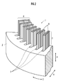
- FIG. 2 is a perspective view showing a part of a workpiece of the stator that is bent by the stator manufacturing apparatus.
- a workpiece 1 to be bent is formed by inserting a plurality of conductor segments 4 for forming a stator coil into each slot 3 of an annular stator core 2. From each slot 3, the end side of each conductor segment 4 extends in the axial direction A of the stator core 2.
- Each extending portion 5 which is an extended portion of each conductor segment 4 constitutes a conductor layer 6 composed of a plurality of layers having different positions in the radial direction R of the stator core 2.
- Each layer constituting the conductor layer 6 is constituted by each extending portion 5 having the same position in the radial direction R in each slot 3. That is, from each slot 3, the same number of extending portions 5 as the number of layers constituting the conductor layer 6 extend at different extending positions in the radial direction R.
- a process of bending the extending portion 5 of the conductor segment 4 extending from each slot 3 of the stator core 2 in the circumferential direction C of the stator core 2 is performed.
- This bending process is performed for each layer constituting the conductor layer 6 (hereinafter referred to as “processed layer”).
- processed layer the layer constituting the conductor layer 6
- the bending process is simultaneously performed for all the extending portions 5 belonging to the processed layer.
- the stator manufacturing apparatus 7 includes a plurality of engaging portions 8 that can be engaged with the distal end portions of the extending portions 5, and a workpiece 1 set in the stator manufacturing apparatus 7.
- the stator core 2 includes a circumferential drive unit 9, a radial drive unit 10, and an axial drive unit 11 that move the respective engaging units 8 in the circumferential direction C, radial direction R, and axial direction A (see FIG. 2).
- the number of engaging portions 8 is the same as the number of slots 3 so that all the extended portions 5 belonging to the processed layer are bent at a time. Are all driven simultaneously and in the same manner.
- the radial direction drive part 10 drives each engagement part 8 to radial direction R according to the extension position in the radial direction R of the extension part 5 which each engagement part 8 should engage.
- the circumferential drive unit 9 holds the radial drive unit 10 and rotates it in the circumferential direction C. Thereby, the circumferential direction drive part 9 can bend each extension part 5 in the circumferential direction C by driving each engagement part 8 engaged with the tip part of each extension part 5 in the circumferential direction C.
- the axial drive unit 11 is provided on the frame 12 of the apparatus and holds the circumferential drive unit 9 to drive in the axial direction A. Thereby, the axial direction drive part 11 drives each engaging part 8 to the axial direction A.
- FIG. When the circumferential drive unit 9 drives each engagement portion 8 in the circumferential direction C and bends each extending portion 5, each of the axial drive units 11 has a drive amount corresponding to the drive amount in the circumferential direction C.
- the engaging portion 8 is driven in the axial direction A.
- FIG. 3 is an exploded view showing a main part of the radial drive unit 10.
- the radial drive unit 10 includes a guide unit 13 that guides each engagement unit 8 to be movable in the radial direction R, a follower unit 14 fixed to each engagement unit 8, and a circumferential direction. And a rotating unit 15 that is rotatably supported by C.
- the rotating portion 15 is provided with the same number of cam grooves 16 as the engaging portion 8.
- the cam groove 16 has an arcuate cam surface that acts on the driven portion 14 of each engaging portion 8 to apply a driving force in the radial direction R to each engaging portion 8 when the rotating portion 15 is rotated.
- the guide portion 13 has the same number of guide grooves 17 in the radial direction R as the engagement portions 8.
- Each engaging portion 8 has three guide pins 18 inserted in the axial direction A with respect to the corresponding guide groove 17.
- Each engagement portion 8 is guided in the radial direction R by the guide portion 13 via the guide pin 18 and the corresponding guide groove 17.
- a spacer 19 is provided between the guide unit 13 and the rotating unit 15.
- the spacer 19 has one surface perpendicular to the axial direction A facing one surface of the guide portion 13 and forms a space for each engaging portion 8 to move in the radial direction R between these facing surfaces.
- Each engaging portion 8 has a roller 20 that rolls on each opposing surface so that it can smoothly move in the radial direction R between these opposing surfaces.
- the spacer 19 has the same number of through grooves 21 as the guide grooves 17 that are long in the radial direction R and penetrate in the axial direction A at positions corresponding to the respective guide grooves 17 of the guide portion 13.
- the driven portion 14 of each engaging portion 8 is inserted in the axial direction A with respect to the corresponding cam groove 16 of the rotating portion 15 through the corresponding through groove 21.
- the driven portion 14 does not contact the through groove 21.
- the rotating unit 15 is rotated in the circumferential direction C via a timing pulley and a timing belt by a motor 22 (see FIG. 1) whose position is fixed to the guide unit 13 and the spacer 19.
- a motor 22 see FIG. 1
- each cam groove 16 of the rotating portion 15 acts on the driven portion 14 of each engaging portion 8.
- each engagement portion 8 is driven in the radial direction R along each guide groove 17 of the guide portion 13.
- each engaging portion 8 is driven in the reverse direction in the radial direction R.
- Each engagement portion 8 includes an engagement tip portion 23 that can be engaged with the tip portion of the extension portion 5 (see FIG. 2), and a tip support portion 24 that supports the engagement tip portion 23 in a replaceable manner.
- the engagement tip portion 23 is attached to the tip support portion 24 by screws 25 so as to be replaceable.
- FIG. 4 illustrates a state in which the engagement tip portion 23 is engaged with the tip portion of the corresponding extension portion 5.
- the front end of the engagement front end portion 23 has a claw shape, and the front end portion of the extension portion 5 is provided with a recess corresponding to the claw-shaped front end portion.
- the claw-like tip of the engagement tip 23 engages with the recess at the tip of the extension 5, and a bending force is applied to the extension 5. That is, the engaging portion 8 can be engaged with the distal end portion of the extending portion 5 when positioned in a position corresponding to the extending position of the extending portion 5 in the radial direction R.
- the stator manufacturing apparatus 7 includes a base end support mechanism 26 that supports the base end portion of each extension portion 5 when each extension portion 5 is bent.
- the base end support mechanism 26 prevents the base end portion of the extension portion 5 from being damaged by the edge portion where the end surface of the stator core 2 and the inner wall of the slot 3 intersect when the extension portion 5 is bent.
- the protruding portion 5 is provided to bend in the circumferential direction C without any trouble at the proximal end portion.
- FIG. 5 is a perspective view showing a main part of the proximal end support mechanism 26.
- the extension part 5 is not shown in FIG.
- the base end support mechanism 26 is disposed on the end face of the stator core 2 and supports a base end portion of each extension portion 5 when the extension portion 5 (see FIG. 2) is bent.
- An end support member 27 and a support member drive unit 28 that drives the base end support member 27 in the radial direction R between a support position for supporting the base end portion of the extending portion 5 and a predetermined retracted position are provided.
- the support member drive unit 28 has the same configuration as the radial drive unit 10 described above.
- the support member drive unit 28 drives the proximal end support member 27 in the radial direction R in the same manner as the radial drive unit 10 drives the engagement unit 8.
- the same number of the proximal support members 27 as the slots 3 are provided, and all of them are driven in the same manner at the same time.
- the support member drive unit 28 rotates in the circumferential direction C, a guide unit 29 that guides each base end support member 27 to be movable in the radial direction R, a driven unit 30 fixed to each base end support member 27. And a rotating part 31 that is freely supported.
- the rotating portion 31 has the same number of arc-shaped cam grooves 32 as the base end support member 27.
- the cam groove 32 acts on the driven portion 30 of each base end support member 27 to apply a driving force in the radial direction R to each base end support member 27 when the rotating portion 31 is rotated.
- the guide portion 29 has the same number of guide grooves 33 in the radial direction R as the base end support member 27 and is fixed to the work support portion 34.
- Each base end support member 27 has three guide pins 35 inserted in the axial direction A with respect to the guide groove 33.
- Each base end support member 27 is guided in the radial direction R by the guide portion 29 via the guide pin 35 and the guide groove 33.
- a spacer 36 is provided between the guide unit 29 and the rotating unit 31.
- one surface perpendicular to the axial direction A is opposed to one surface of the guide portion 29, and a space for moving each base end support member 27 in the radial direction R between these opposed surfaces is provided. It fixes to the guide part 29 so that it may form.
- the spacer 36 has the same number of through grooves 37 as the guide grooves 33 that are long in the radial direction R and penetrate in the axial direction A at positions corresponding to the respective guide grooves 33 of the guide portion 29.
- the driven portion 30 of each base end support member 27 is inserted in the axial direction A with respect to the corresponding cam groove 32 of the rotating portion 31 via the corresponding through groove 37.
- the driven portion 30 does not contact the through groove 37.
- the rotating unit 31 is rotated in the circumferential direction C via a timing pulley and a timing belt by a motor 38 (see FIG. 1) fixed to the frame 12.
- a motor 38 (see FIG. 1) fixed to the frame 12.
- each cam groove 32 of the rotating portion 31 acts on the driven portion 30 of each proximal end support member 27, and each proximal end support member 27 is moved to each guide portion 29.
- the stator manufacturing apparatus 7 further includes a work support portion 34 that supports the workpiece 1 of FIG. 2, and a base end portion and a distal end portion of each extension portion 5 that is bent by the circumferential drive portion 9. And an expansion portion 39 that expands outward by pressing an intermediate portion between the portions from the inside in the radial direction R.
- the work support portion 34 is provided on the frame 12.
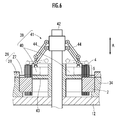
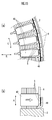
- FIG. 6 is a cross-sectional view showing the main part of the expansion part 39.
- the extended portion 39 includes a pressing member 40 for pressing an intermediate portion of each extending portion 5, and a pressing member driving portion 41 that drives the pressing member 40 in the radial direction R.
- the pressing members 40 are provided in the same number as the slots 3 (see FIG. 1).
- the pressing member driving portion 41 drives the pressing member 40 in the radial direction R in the space between the extending portions 5 extending from each slot 3. At that time, all the pressing members 40 are simultaneously driven in the radial direction R in the same manner.
- the pressing member driving unit 41 includes a lifting shaft 42 driven in the axial direction A, a metal guide 43 fixed to the frame 12, and a link mechanism 44 interposed between the lifting shaft 42 and each pressing member 40. .
- the link mechanism 44 is provided in the same number as the pressing member 40.
- the elevating shaft 42 is driven in the axial direction A by a motor 45 shown in FIG. 1 via a timing pulley, a timing belt, a ball screw, and the like.
- the metal guide 43 guides each pressing member 40 to be movable in the radial direction R.
- Each link mechanism 44 converts the movement of the lifting shaft 42 in the axial direction A into the movement of each pressing member 40 in the radial direction R following the guidance by the metal guide 43.
- the expansion part 39 expands the intermediate part of each bent extension part 5 by the movement of each pressing member 40.
- FIG. 7 is a flowchart showing a bending process performed by the stator manufacturing apparatus 7. As shown in FIG. 7, in the bending process, first, the workpiece 1 to be processed is attached to the stator manufacturing apparatus 7 (step S1).
- This attachment is performed by supporting the workpiece 1 on the workpiece support 34.
- the conductor segment 4 is inserted into each slot 3 of the stator core 2, and the conductor layer 6 is formed by the extending portion 5.
- each base end support member 27 is driven from a predetermined retracted position to a support position inward in the radial direction R by the support member driving unit 28 (step S2). Thereby, each base end supporting member 27 is disposed at a position where the base end portion of each extending portion 5 can be supported, as shown in FIG. 5.
- the positioning of the engaging portion 8 in step S3 and the bending process in steps S4 to S7 are repeated as many times as the number of processed layers constituting the conductor layer 6.
- the bending process is performed on all the extending portions 5 of one processed layer by one bending process.
- Each bending process is sequentially performed for each processing layer from the outermost outermost processing layer to the innermost innermost processing layer among the processing layers constituting the conductor layer 6.
- step S3 the engaging portion 8 is applied to each extending portion 5 belonging to one processed layer subjected to the current bending process by the axial direction driving portion 11, the radial direction driving portion 10, and the like. As shown in FIG.
- each engagement portion 8 is driven in the radial direction R by the radial direction drive portion 10 so as to be positioned in the radial direction R corresponding to the extension position of each extension portion 5 (radial direction). Driving process). At this time, each engaging portion 8 is driven in the circumferential direction C and the axial direction A by the circumferential direction driving portion 9 and the axial direction driving portion 11 as necessary.
- step S4 the extension 5 is slightly bent.
- each engagement portion 8 is driven in the circumferential direction C and the axial direction A by the circumferential direction driving portion 9 and the axial direction driving portion 11.
- the engagement tip portion 23 of each engagement portion 8 is engaged with the tip portion of the extension portion 5.
- this driving is performed so that the positional relationship between each engaging portion 8 and the tip end portion of each extending portion 5 engaged therewith is kept constant and the engaged state is maintained. Further, this driving is performed such that the position in the circumferential direction C of the distal end portion of each extending portion 5 is moved from the initial position by about half of the interval between the adjacent slots 3.
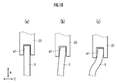
- each extension part 5 will be in the state bent a little like FIG. FIGS. 11A and 11B schematically show how this state is seen in the axial direction A and the circumferential direction C, respectively.
- step S5 an expansion process is performed in which each extending portion 5 bent in step S4 is pressed from the inside in the radial direction R to expand outward. That is, the elevating shaft 42 is driven in the axial direction A in the extension portion 39, and the pressing member 40 is moved to a predetermined position outside the radial direction R.
- each engagement portion 8 is driven outward in the radial direction R by the radial direction drive portion 10 so that the engagement with the distal end portion of each extension portion 5 is maintained.
- each extended part 5 bent a little by step S4 will be in the state expanded outward of radial direction R so that it may be illustrated in FIG.
- step S6 each extending portion 5 is further bent. That is, the engaging portions 8 are further driven in the circumferential direction C and the axial direction A by the circumferential direction drive unit 9 and the axial direction drive unit 11 while the pressing member 40 is disposed at the predetermined position.
- This driving is performed so that the positional relationship between each engaging portion 8 and the tip portion of each extending portion 5 engaged with the engaging portion 8 is kept constant, and the engaged state is maintained. Further, this drive is such that the position in the circumferential direction C of the distal end portion of each extending portion 5 is moved from the initial position in FIG. 8 to the circumferential direction C by about three times the interval between adjacent slots 3. To be done.
- each extending portion 5 is bent along the end surface of the corresponding pressing member 40 on the outer side in the radial direction R while being expanded outward in the radial direction R by the end surface.
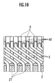
- each extending part 5 is in the state illustrated in FIG. 10 as viewed in the radial direction R, and the state viewed in the axial direction A and the circumferential direction C is in the state illustrated in FIG. .
- step S7 as shown in FIG. 14, if necessary, the interphase paper 46 for insulating the coils of the adjacent phases is provided with each extension portion of the processing layer that is the object of the current bending process. 5 and each extending portion 5 of the processed layer to be subjected to the next bending process. Thereby, the bending process for one processed layer of the conductor layer 6 is completed.
- step S8 it is determined whether or not the processing layer subjected to the current bending process (first bending process) is the innermost innermost processing layer in the radial direction R. If it is not the innermost processed layer, the process returns to step S3, and each extending portion 5 belonging to the next processed layer is subjected to the next bending step (second bending step) of steps S3 to S6. However, in the next bending step, the extension portion 5 is bent in a direction opposite to the bending direction of the extension portion 5 in the current bending step, if necessary.
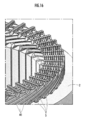
- FIG. 15 shows a state when the bending direction is reversed. That is, for the outermost processed layer, the folding direction is clockwise with respect to the circumferential direction C, while the innermost processed layer is counterclockwise. In addition, about the one inner side processed layer, the extension part 5 of the state slightly bent by step S4 is shown.
- Step S8 when it is determined that the processed layer subjected to the current bending process is the innermost processed layer, the bending process of FIG. 7 ends.
- the workpiece 1 after the bending process is in a state shown in FIG. About this workpiece 1, after that, the front-end
- each gap for inserting the interphase paper 46 can be adjusted to be constant by changing the expansion amount in the expansion process for each processed layer.
- the engaging portion 8 can be driven in the radial direction R, a plurality of extending portions 5 whose extending positions are different in the radial direction by one engaging portion 8. Can be bent. Moreover, it can respond also to the workpiece 1 from which the extension position of the extension part 5 differs.
- the engaging portion 8 when the engaging portion 8 is driven in the circumferential direction and the extending portion 5 is bent, the engaging portion 8 can also be driven in the radial direction, so that the extending portion 5 is bent while being expanded in the radial direction R. Even in this case, the engaging portion 8 can be made to follow the distal end portion of the extending portion 5 so that the engaged state between the engaging portion 8 and the distal end portion of the extending portion 5 can be maintained.
- the extension portion 5 can be bent without any trouble while maintaining the engagement state between the engagement portion 8 and the distal end portion of the extension portion 5.
- the radial direction drive part 10 was comprised using the guide part 13, the driven part 14, and the rotation part 15, it is not necessary to provide the drive mechanism for every engaging part 8, and it is one process by a compact and simple structure. All the engaging portions 8 belonging to the layer can be simultaneously driven in the radial direction R.
- the engaging part 8 is comprised by the engagement front-end
- the tip of the engaging portion 8 can be easily replaced.
- the support member drive unit 28 for driving the base end support member 27 between a support position for supporting the base end portion of the extension portion 5 and a predetermined retracted position is provided, a conductor segment extending from each slot 3 is provided. Regardless of the shape of 4, the base end support member 27 can be easily disposed at the support position.
- each extending portion 5 extending in the axial direction A from the first extending position and the second extending position, which are different extending positions in the radial direction R, respectively.
- the engaging portion 8 in the first bending step, is engaged with the tip end portion of the first extending portion, and is driven in one direction along the circumferential direction C to move the first extending portion in the one direction. Bend it.
- the engaging portion 8 In the radial movement step, the engaging portion 8 is driven in the radial direction R to a position corresponding to the second extending position.
- the engaging part 8 in a 2nd bending process, is engaged with the front-end
- the first extending portion and the second extending portion can be bent by the same engaging portion 8. Moreover, it can respond also when manufacturing the stator from which a 1st extension position and a 2nd extension position differ variously.
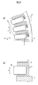
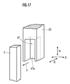
- the engagement tip portion 23 of the engagement portion 8 is replaced with a recess 47 that engages with the tip portion of the extension portion 5 as shown in FIG. It may be provided.
- the recess 47 has a rectangular parallelepiped shape that is long in the axial direction A. The three opposing faces of the rectangular parallelepiped shape are perpendicular to the axial direction A, the circumferential direction C, and the radial direction R, respectively.
- One of the opposing surfaces perpendicular to the axial direction A is an open surface opened at the distal end surface of the engagement distal end portion 23.
- One of the opposing surfaces perpendicular to the radial direction R is an open surface that is open on the surface inside the radial direction R of the engagement tip 23. That is, the recessed part 47 is comprised by four surfaces other than these two open surfaces. The size of the recess 47 is larger than that of the tip so that a slight gap is generated when the tip of the extension portion 5 is fitted into the recess 47.
- the engaging tip portion 23 can be fitted to the tip portion of the extending portion 5 and can be positioned also in the radial direction R.
- the inner wall 47 a perpendicular to the radial direction R of the recess 47 is used for positioning in the radial direction R.
- the extending portion 5 can be bent.
- the present invention is used to bend a conductor segment for constituting a stator coil in the manufacture of a stator used in a motor. In that case, it can respond to manufacture of the various stator from which the number and position of a conductor segment differ.
Landscapes
- Engineering & Computer Science (AREA)
- Manufacturing & Machinery (AREA)
- Power Engineering (AREA)
- Manufacture Of Motors, Generators (AREA)
- Windings For Motors And Generators (AREA)
Description
、各基端支持部材27が、図5に示されるように、各延出部5の基端部を支持し得る位置に配置される。
Claims (6)
- 環状のステータコアの径方向に異なる複数の延出位置において該ステータコアのスロットから軸方向に延出した複数の導体セグメントの延出部を折り曲げるステータ製造装置であって、
前記径方向において前記延出部の延出位置に対応する位置で該延出部の先端部に係合可能な係合部と、
前記延出部の先端部に係合した前記係合部を前記ステータコアの周方向に駆動して該延出部を折り曲げる周方向駆動部と、
前記係合部を前記径方向に駆動する径方向駆動部とを備えるステータ製造装置。 - 前記係合部を前記ステータコアの軸方向に駆動する軸方向駆動部を備える請求項1に記載のステータ製造装置。
- 前記径方向駆動部は、
前記係合部を前記径方向に移動自在に案内する案内部と、
前記係合部に固定された従動部と、
前記ステータコアの周方向に回転自在に支持された回転部とを備え、
前記回転部は、回転されたときに前記係合部の従動部に作用して該係合部に前記径方向の駆動力を付与する円弧状のカム面を有する請求項1に記載のステータ製造装置。 - 前記係合部は、
前記延出部の先端部に係合する係合先端部と、
前記係合先端部を交換可能に支持する先端支持部とを備える請求項1に記載のステータ製造装置。 - 前記ステータコアの端面上に配置され、前記延出部が折り曲げられるときに該延出部の基端部を支持する基端支持部材と、
前記延出部の基端部を支持する支持位置と所定の退避位置との間で前記基端支持部材を前記径方向に駆動する支持部材駆動部とを備える請求項1に記載のステータ製造装置。 - 環状のステータコアに形成されたスロットにおいて、該ステータコアの径方向に異なる第1延出位置及び第2延出位置から該ステータコアの軸方向にそれぞれ延出した導体セグメントの第1延出部及び第2延出部を折り曲げるステータ製造方法であって、
それぞれ前記第1延出位置及び第2延出位置に対応する前記径方向の位置で前記第1延出部及び第2延出部の先端部に係合可能な係合部を、該第1延出部の先端部に係合させ、前記ステータコアの周方向に沿った一方向に駆動して該第1延出部を該一方向に折り曲げる第1折曲げ工程と、
前記第1折曲げ工程の後、前記係合部を前記第2延出位置に対応する位置へ前記径方向に駆動する径方向駆動工程と、
前記径方向駆動工程の後、前記係合部を前記第2延出部の先端部に係合させ、前記一方向とは逆方向に駆動して該第2延出部を該逆方向に折り曲げる第2折曲げ工程とを備えるステータ製造方法。
Priority Applications (2)
| Application Number | Priority Date | Filing Date | Title |
|---|---|---|---|
| JP2014520967A JP5782566B2 (ja) | 2012-06-22 | 2013-02-12 | ステータ製造装置及びステータ製造方法 |
| US14/408,095 US10284057B2 (en) | 2012-06-22 | 2013-02-12 | Stator manufacturing device and stator manufacturing method |
Applications Claiming Priority (2)
| Application Number | Priority Date | Filing Date | Title |
|---|---|---|---|
| JP2012140639 | 2012-06-22 | ||
| JP2012-140639 | 2012-06-22 |
Publications (1)
| Publication Number | Publication Date |
|---|---|
| WO2013190860A1 true WO2013190860A1 (ja) | 2013-12-27 |
Family
ID=49768470
Family Applications (1)
| Application Number | Title | Priority Date | Filing Date |
|---|---|---|---|
| PCT/JP2013/053246 Ceased WO2013190860A1 (ja) | 2012-06-22 | 2013-02-12 | ステータ製造装置及びステータ製造方法 |
Country Status (3)
| Country | Link |
|---|---|
| US (1) | US10284057B2 (ja) |
| JP (1) | JP5782566B2 (ja) |
| WO (1) | WO2013190860A1 (ja) |
Cited By (10)
| Publication number | Priority date | Publication date | Assignee | Title |
|---|---|---|---|---|
| US9479033B2 (en) | 2011-05-16 | 2016-10-25 | Atop S.P.A. | Apparatus and method for manufacturing coil members for cores of dynamo electric machines by bending |
| JP2017085678A (ja) * | 2015-10-22 | 2017-05-18 | トヨタ自動車株式会社 | コイルエンド折曲治具及びコイルエンド折曲方法 |
| JP2017085806A (ja) * | 2015-10-29 | 2017-05-18 | トヨタ自動車株式会社 | ステータ用セグメントコイルのコイルエンド接合方法 |
| US9692283B2 (en) | 2014-03-07 | 2017-06-27 | Atop S.P.A | Apparatus and method for forming coil members |
| US10224789B2 (en) | 2011-03-07 | 2019-03-05 | Atop S.P.A. | Apparatus for aligning conductors of coil members in cores of electric dynamo machines |
| US10305354B2 (en) | 2013-10-18 | 2019-05-28 | Atop S.P.A. | Apparatus for manufacturing components of dynamoelectric machines |
| WO2019123977A1 (ja) * | 2017-12-21 | 2019-06-27 | 日立オートモティブシステムズ株式会社 | 固定子の製造方法 |
| US10749418B2 (en) | 2015-04-30 | 2020-08-18 | Atop S.P.A. | Methods for forming woven undulated coil assemblies |
| JPWO2021019749A1 (ja) * | 2019-07-31 | 2021-02-04 | ||
| US11557946B2 (en) | 2015-07-20 | 2023-01-17 | Atop S.P.A. | Method for inserting undulated coil assemblies in slots of cores of dynamoelectric machines |
Families Citing this family (21)
| Publication number | Priority date | Publication date | Assignee | Title |
|---|---|---|---|---|
| DE102015217922A1 (de) * | 2015-09-18 | 2017-03-23 | Continental Automotive Gmbh | Verfahren und zweiteilige Werkzeuganordnung zum Herstellen eines Stators für eine elektrische Maschine |
| DE102015217936A1 (de) * | 2015-09-18 | 2017-03-23 | Continental Automotive Gmbh | Verfahren und einteilige Werkzeuganordnung zum Herstellen eines Stators für eine elektrische Maschine |
| US10425229B2 (en) * | 2016-02-12 | 2019-09-24 | Microsoft Technology Licensing, Llc | Secure provisioning of operating systems |
| JP6305471B2 (ja) * | 2016-07-25 | 2018-04-04 | 本田技研工業株式会社 | ステータの製造方法及びその装置 |
| DE102018103100A1 (de) | 2017-07-04 | 2019-01-10 | Grob-Werke Gmbh & Co. Kg | Verfahren und Vorrichtung zum Positionieren und Spannen von Drahtenden für elektrische Maschinen |
| JP6779527B2 (ja) * | 2017-08-04 | 2020-11-04 | 株式会社小田原エンジニアリング | コイル組立装置、コイル組立方法及び回転電機の製造装置 |
| DE102017213967A1 (de) * | 2017-08-10 | 2019-02-14 | Bayerische Motoren Werke Aktiengesellschaft | Vorrichtung zum Bearbeiten von Wicklungen |
| CN111434015B (zh) | 2017-11-13 | 2022-10-11 | 小田原机械工程株式会社 | 线圈段处理方法、线圈段处理装置以及线圈段的连接结构 |
| JP7066466B2 (ja) * | 2018-03-22 | 2022-05-13 | 本田技研工業株式会社 | 捻り曲げ装置 |
| MX2020012958A (es) * | 2018-09-17 | 2021-02-16 | Tecnomatic Spa | Aparato y proceso para deformar conductores que sobresalen de un lado de un estator o de un rotor de una maquina electrica. |
| DE102019201037A1 (de) * | 2019-01-28 | 2020-01-02 | Thyssenkrupp Ag | Positioniervorrichtung zur Positionierung von Kupferstäben |
| AT522292A1 (de) * | 2019-04-11 | 2020-10-15 | Miba Automation Systems Ges M B H | Verfahren sowie Umformeinheit zum Umformen von freien Stabendabschnitten eines Blechpakets |
| DE102019207126A1 (de) * | 2019-05-16 | 2020-11-19 | Thyssenkrupp Ag | Greifervorrichtung |
| DE102019211859A1 (de) * | 2019-08-07 | 2021-02-11 | Felsomat Gmbh & Co. Kg | Fertigungssystem und Verfahren zum Fertigen eines Stators mit Stableitern |
| DE102019219500A1 (de) * | 2019-12-12 | 2021-06-17 | Thyssenkrupp Ag | Biegevorrichtung für Kupferstäbe |
| DE102020106430A1 (de) | 2020-03-10 | 2021-09-16 | Schaeffler Technologies AG & Co. KG | Verteilte Wicklung für einen Elektromotor mit nach außen und zurückgebogenen freien Enden, Elektromotor, Werkzeug zum Herstellen und Herstellverfahren |
| DE102020204278A1 (de) | 2020-04-02 | 2021-10-07 | Thyssenkrupp Ag | Positioniervorrichtung und Verfahren zum umfänglichen Positionieren von Kupferstäben |
| KR102804916B1 (ko) * | 2020-09-04 | 2025-05-08 | 현대자동차 주식회사 | 평각형 고정자 코일의 인서팅 가이드 장치 |
| IT202000030824A1 (it) * | 2020-12-15 | 2022-06-15 | Tecnomatic Spa | Apparato e procedimento per la deformazione di conduttori di almeno un gruppo di avvolgimento, sporgenti da un lato di uno statore o di un rotore di una macchina elettrica |
| DE112022001441A5 (de) * | 2021-03-11 | 2024-01-25 | Miba Automation Systems Ges.M.B.H. | Vorrichtung und verfahren zum verformen von freien stabendabschnitten eines leiterpaketes |
| CN116418154B (zh) * | 2021-12-31 | 2026-04-17 | 联合汽车电子有限公司 | 绕组端部加工方法、绕组端部结构及定子组件 |
Citations (3)
| Publication number | Priority date | Publication date | Assignee | Title |
|---|---|---|---|---|
| JP2002010585A (ja) * | 2000-05-11 | 2002-01-11 | Valeo Equip Electric Moteur | 回転電気機器のステータの巻線ヘッドを所定形状に形成するための装置 |
| JP2003259612A (ja) * | 2002-02-27 | 2003-09-12 | Denso Corp | 回転電機の巻線接合方法 |
| JP2004236375A (ja) * | 2003-01-28 | 2004-08-19 | Toyota Motor Corp | コイルの捻り成形方法および捻り治具 |
Family Cites Families (3)
| Publication number | Priority date | Publication date | Assignee | Title |
|---|---|---|---|---|
| JP3196738B2 (ja) | 1998-09-11 | 2001-08-06 | 株式会社デンソー | ステータ製造装置及びステータ製造方法 |
| JP3975947B2 (ja) * | 2003-03-07 | 2007-09-12 | 株式会社デンソー | 回転電機の巻線の製造方法 |
| JP5434704B2 (ja) * | 2010-03-12 | 2014-03-05 | 株式会社豊田自動織機 | 回転電機のステータの製造方法及び製造装置 |
-
2013
- 2013-02-12 WO PCT/JP2013/053246 patent/WO2013190860A1/ja not_active Ceased
- 2013-02-12 JP JP2014520967A patent/JP5782566B2/ja not_active Expired - Fee Related
- 2013-02-12 US US14/408,095 patent/US10284057B2/en active Active
Patent Citations (3)
| Publication number | Priority date | Publication date | Assignee | Title |
|---|---|---|---|---|
| JP2002010585A (ja) * | 2000-05-11 | 2002-01-11 | Valeo Equip Electric Moteur | 回転電気機器のステータの巻線ヘッドを所定形状に形成するための装置 |
| JP2003259612A (ja) * | 2002-02-27 | 2003-09-12 | Denso Corp | 回転電機の巻線接合方法 |
| JP2004236375A (ja) * | 2003-01-28 | 2004-08-19 | Toyota Motor Corp | コイルの捻り成形方法および捻り治具 |
Cited By (16)
| Publication number | Priority date | Publication date | Assignee | Title |
|---|---|---|---|---|
| US10224789B2 (en) | 2011-03-07 | 2019-03-05 | Atop S.P.A. | Apparatus for aligning conductors of coil members in cores of electric dynamo machines |
| US9479033B2 (en) | 2011-05-16 | 2016-10-25 | Atop S.P.A. | Apparatus and method for manufacturing coil members for cores of dynamo electric machines by bending |
| US10411570B2 (en) | 2011-05-16 | 2019-09-10 | Atop S.P.A. | Apparatus for manufacturing coil members for cores of dynamo electric machines by bending |
| US10305354B2 (en) | 2013-10-18 | 2019-05-28 | Atop S.P.A. | Apparatus for manufacturing components of dynamoelectric machines |
| US9692283B2 (en) | 2014-03-07 | 2017-06-27 | Atop S.P.A | Apparatus and method for forming coil members |
| US10749418B2 (en) | 2015-04-30 | 2020-08-18 | Atop S.P.A. | Methods for forming woven undulated coil assemblies |
| US11336160B2 (en) | 2015-04-30 | 2022-05-17 | Atop S.Pa. | Methods for forming woven undulated coil assemblies |
| US11658553B2 (en) | 2015-04-30 | 2023-05-23 | Atop S.P.A. | Apparatuses for forming woven undulated coil assemblies |
| US11557946B2 (en) | 2015-07-20 | 2023-01-17 | Atop S.P.A. | Method for inserting undulated coil assemblies in slots of cores of dynamoelectric machines |
| US12470114B2 (en) | 2015-07-20 | 2025-11-11 | Atop S.P.A. | Apparatus for inserting an undulated coil assembly in slots of a core of a stator of a dynamoelectric machine |
| JP2017085678A (ja) * | 2015-10-22 | 2017-05-18 | トヨタ自動車株式会社 | コイルエンド折曲治具及びコイルエンド折曲方法 |
| JP2017085806A (ja) * | 2015-10-29 | 2017-05-18 | トヨタ自動車株式会社 | ステータ用セグメントコイルのコイルエンド接合方法 |
| WO2019123977A1 (ja) * | 2017-12-21 | 2019-06-27 | 日立オートモティブシステムズ株式会社 | 固定子の製造方法 |
| JPWO2019123977A1 (ja) * | 2017-12-21 | 2020-11-19 | 日立オートモティブシステムズ株式会社 | 固定子の製造方法 |
| JPWO2021019749A1 (ja) * | 2019-07-31 | 2021-02-04 | ||
| WO2021019749A1 (ja) * | 2019-07-31 | 2021-02-04 | 株式会社 東芝 | 固定子の製造方法 |
Also Published As
| Publication number | Publication date |
|---|---|
| JP5782566B2 (ja) | 2015-09-24 |
| US10284057B2 (en) | 2019-05-07 |
| US20150180319A1 (en) | 2015-06-25 |
| JPWO2013190860A1 (ja) | 2016-02-08 |
Similar Documents
| Publication | Publication Date | Title |
|---|---|---|
| JP5782566B2 (ja) | ステータ製造装置及びステータ製造方法 | |
| JP5869434B2 (ja) | ステータ製造方法及びステータ製造装置 | |
| JP5233682B2 (ja) | 曲げ加工機 | |
| JP7172834B2 (ja) | 整列装置および整列コイルの製造方法 | |
| JP4616131B2 (ja) | エッジワイズコイル巻線方法及び装置 | |
| JP5699054B2 (ja) | コイル挿入方法及びコイル挿入装置 | |
| JP6642494B2 (ja) | 回転電機のステータの製造装置 | |
| WO2011111682A1 (ja) | 回転電機のステータ、ステータの製造方法、及びステータにおけるコイル製造方法 | |
| EP3379704A1 (en) | Coil forming device and coil forming method | |
| US10418887B2 (en) | Stator assembly method and stator assembly apparatus | |
| CN111201700B (zh) | 用于制造定子的半成品的方法和用于制造定子的半成品的设备 | |
| JP5233901B2 (ja) | 曲げ加工方法 | |
| JP5046754B2 (ja) | コイル挿入装置 | |
| US20230318414A1 (en) | Coil insertion apparatus and coil insertion method | |
| JP2011036874A (ja) | 曲げ加工装置 | |
| JP6111135B2 (ja) | 捻り曲げ装置 | |
| JP6202961B2 (ja) | ステータ及びその製造方法 | |
| JP7693084B2 (ja) | ステータの製造装置、ステータの製造方法及びステータ | |
| JP5402503B2 (ja) | 回転電機の固定子又は回転子のコイル成形装置 | |
| JP7797996B2 (ja) | 巻線用整形装置及び巻線用整形方法 | |
| JP5505527B2 (ja) | 曲げ加工装置及び曲げ加工機 | |
| JPWO2023162403A5 (ja) | ||
| CN115694098A (zh) | 保持装置、定子的制造方法 | |
| JP7474816B2 (ja) | ステータ製造装置及びステータ製造方法 | |
| JP4713222B2 (ja) | 巻線方法及び巻線装置 |
Legal Events
| Date | Code | Title | Description |
|---|---|---|---|
| 121 | Ep: the epo has been informed by wipo that ep was designated in this application |
Ref document number: 13807785 Country of ref document: EP Kind code of ref document: A1 |
|
| ENP | Entry into the national phase |
Ref document number: 2014520967 Country of ref document: JP Kind code of ref document: A |
|
| WWE | Wipo information: entry into national phase |
Ref document number: 14408095 Country of ref document: US |
|
| NENP | Non-entry into the national phase |
Ref country code: DE |
|
| 122 | Ep: pct application non-entry in european phase |
Ref document number: 13807785 Country of ref document: EP Kind code of ref document: A1 |