WO2014002745A1 - シール材および押輪および継手および弁 - Google Patents
シール材および押輪および継手および弁 Download PDFInfo
- Publication number
- WO2014002745A1 WO2014002745A1 PCT/JP2013/066013 JP2013066013W WO2014002745A1 WO 2014002745 A1 WO2014002745 A1 WO 2014002745A1 JP 2013066013 W JP2013066013 W JP 2013066013W WO 2014002745 A1 WO2014002745 A1 WO 2014002745A1
- Authority
- WO
- WIPO (PCT)
- Prior art keywords
- receiving port
- valve
- sealing material
- port
- push
- Prior art date
- Legal status (The legal status is an assumption and is not a legal conclusion. Google has not performed a legal analysis and makes no representation as to the accuracy of the status listed.)
- Ceased
Links
Images










Classifications
-
- F—MECHANICAL ENGINEERING; LIGHTING; HEATING; WEAPONS; BLASTING
- F16—ENGINEERING ELEMENTS AND UNITS; GENERAL MEASURES FOR PRODUCING AND MAINTAINING EFFECTIVE FUNCTIONING OF MACHINES OR INSTALLATIONS; THERMAL INSULATION IN GENERAL
- F16L—PIPES; JOINTS OR FITTINGS FOR PIPES; SUPPORTS FOR PIPES, CABLES OR PROTECTIVE TUBING; MEANS FOR THERMAL INSULATION IN GENERAL
- F16L21/00—Joints with sleeve or socket
- F16L21/02—Joints with sleeve or socket with elastic sealing rings between pipe and sleeve or between pipe and socket, e.g. with rolling or other prefabricated profiled rings
- F16L21/03—Joints with sleeve or socket with elastic sealing rings between pipe and sleeve or between pipe and socket, e.g. with rolling or other prefabricated profiled rings placed in the socket before connection
-
- F—MECHANICAL ENGINEERING; LIGHTING; HEATING; WEAPONS; BLASTING
- F16—ENGINEERING ELEMENTS AND UNITS; GENERAL MEASURES FOR PRODUCING AND MAINTAINING EFFECTIVE FUNCTIONING OF MACHINES OR INSTALLATIONS; THERMAL INSULATION IN GENERAL
- F16J—PISTONS; CYLINDERS; SEALINGS
- F16J15/00—Sealings
- F16J15/02—Sealings between relatively-stationary surfaces
- F16J15/021—Sealings between relatively-stationary surfaces with elastic packing
- F16J15/022—Sealings between relatively-stationary surfaces with elastic packing characterised by structure or material
-
- F—MECHANICAL ENGINEERING; LIGHTING; HEATING; WEAPONS; BLASTING
- F16—ENGINEERING ELEMENTS AND UNITS; GENERAL MEASURES FOR PRODUCING AND MAINTAINING EFFECTIVE FUNCTIONING OF MACHINES OR INSTALLATIONS; THERMAL INSULATION IN GENERAL
- F16J—PISTONS; CYLINDERS; SEALINGS
- F16J15/00—Sealings
- F16J15/02—Sealings between relatively-stationary surfaces
- F16J15/021—Sealings between relatively-stationary surfaces with elastic packing
- F16J15/028—Sealings between relatively-stationary surfaces with elastic packing the packing being mechanically expanded against the sealing surface
-
- F—MECHANICAL ENGINEERING; LIGHTING; HEATING; WEAPONS; BLASTING
- F16—ENGINEERING ELEMENTS AND UNITS; GENERAL MEASURES FOR PRODUCING AND MAINTAINING EFFECTIVE FUNCTIONING OF MACHINES OR INSTALLATIONS; THERMAL INSULATION IN GENERAL
- F16K—VALVES; TAPS; COCKS; ACTUATING-FLOATS; DEVICES FOR VENTING OR AERATING
- F16K27/00—Construction of housing; Use of materials therefor
-
- F—MECHANICAL ENGINEERING; LIGHTING; HEATING; WEAPONS; BLASTING
- F16—ENGINEERING ELEMENTS AND UNITS; GENERAL MEASURES FOR PRODUCING AND MAINTAINING EFFECTIVE FUNCTIONING OF MACHINES OR INSTALLATIONS; THERMAL INSULATION IN GENERAL
- F16K—VALVES; TAPS; COCKS; ACTUATING-FLOATS; DEVICES FOR VENTING OR AERATING
- F16K27/00—Construction of housing; Use of materials therefor
- F16K27/04—Construction of housing; Use of materials therefor of sliding valves
- F16K27/044—Construction of housing; Use of materials therefor of sliding valves slide valves with flat obturating members
-
- F—MECHANICAL ENGINEERING; LIGHTING; HEATING; WEAPONS; BLASTING
- F16—ENGINEERING ELEMENTS AND UNITS; GENERAL MEASURES FOR PRODUCING AND MAINTAINING EFFECTIVE FUNCTIONING OF MACHINES OR INSTALLATIONS; THERMAL INSULATION IN GENERAL
- F16K—VALVES; TAPS; COCKS; ACTUATING-FLOATS; DEVICES FOR VENTING OR AERATING
- F16K3/00—Gate valves or sliding valves, i.e. cut-off apparatus with closing members having a sliding movement along the seat for opening and closing
- F16K3/30—Details
-
- F—MECHANICAL ENGINEERING; LIGHTING; HEATING; WEAPONS; BLASTING
- F16—ENGINEERING ELEMENTS AND UNITS; GENERAL MEASURES FOR PRODUCING AND MAINTAINING EFFECTIVE FUNCTIONING OF MACHINES OR INSTALLATIONS; THERMAL INSULATION IN GENERAL
- F16L—PIPES; JOINTS OR FITTINGS FOR PIPES; SUPPORTS FOR PIPES, CABLES OR PROTECTIVE TUBING; MEANS FOR THERMAL INSULATION IN GENERAL
- F16L21/00—Joints with sleeve or socket
- F16L21/02—Joints with sleeve or socket with elastic sealing rings between pipe and sleeve or between pipe and socket, e.g. with rolling or other prefabricated profiled rings
- F16L21/04—Joints with sleeve or socket with elastic sealing rings between pipe and sleeve or between pipe and socket, e.g. with rolling or other prefabricated profiled rings in which sealing rings are compressed by axially-movable members
-
- F—MECHANICAL ENGINEERING; LIGHTING; HEATING; WEAPONS; BLASTING
- F16—ENGINEERING ELEMENTS AND UNITS; GENERAL MEASURES FOR PRODUCING AND MAINTAINING EFFECTIVE FUNCTIONING OF MACHINES OR INSTALLATIONS; THERMAL INSULATION IN GENERAL
- F16L—PIPES; JOINTS OR FITTINGS FOR PIPES; SUPPORTS FOR PIPES, CABLES OR PROTECTIVE TUBING; MEANS FOR THERMAL INSULATION IN GENERAL
- F16L21/00—Joints with sleeve or socket
- F16L21/08—Joints with sleeve or socket with additional locking means
-
- F—MECHANICAL ENGINEERING; LIGHTING; HEATING; WEAPONS; BLASTING
- F16—ENGINEERING ELEMENTS AND UNITS; GENERAL MEASURES FOR PRODUCING AND MAINTAINING EFFECTIVE FUNCTIONING OF MACHINES OR INSTALLATIONS; THERMAL INSULATION IN GENERAL
- F16L—PIPES; JOINTS OR FITTINGS FOR PIPES; SUPPORTS FOR PIPES, CABLES OR PROTECTIVE TUBING; MEANS FOR THERMAL INSULATION IN GENERAL
- F16L23/00—Flanged joints
- F16L23/02—Flanged joints the flanges being connected by members tensioned axially
- F16L23/024—Flanged joints the flanges being connected by members tensioned axially characterised by how the flanges are joined to, or form an extension of, the pipes
-
- F—MECHANICAL ENGINEERING; LIGHTING; HEATING; WEAPONS; BLASTING
- F16—ENGINEERING ELEMENTS AND UNITS; GENERAL MEASURES FOR PRODUCING AND MAINTAINING EFFECTIVE FUNCTIONING OF MACHINES OR INSTALLATIONS; THERMAL INSULATION IN GENERAL
- F16L—PIPES; JOINTS OR FITTINGS FOR PIPES; SUPPORTS FOR PIPES, CABLES OR PROTECTIVE TUBING; MEANS FOR THERMAL INSULATION IN GENERAL
- F16L23/00—Flanged joints
- F16L23/02—Flanged joints the flanges being connected by members tensioned axially
- F16L23/032—Flanged joints the flanges being connected by members tensioned axially characterised by the shape or composition of the flanges
-
- F—MECHANICAL ENGINEERING; LIGHTING; HEATING; WEAPONS; BLASTING
- F16—ENGINEERING ELEMENTS AND UNITS; GENERAL MEASURES FOR PRODUCING AND MAINTAINING EFFECTIVE FUNCTIONING OF MACHINES OR INSTALLATIONS; THERMAL INSULATION IN GENERAL
- F16L—PIPES; JOINTS OR FITTINGS FOR PIPES; SUPPORTS FOR PIPES, CABLES OR PROTECTIVE TUBING; MEANS FOR THERMAL INSULATION IN GENERAL
- F16L37/00—Couplings of the quick-acting type
- F16L37/08—Couplings of the quick-acting type in which the connection between abutting or axially overlapping ends is maintained by locking members
- F16L37/084—Couplings of the quick-acting type in which the connection between abutting or axially overlapping ends is maintained by locking members combined with automatic locking
- F16L37/0845—Couplings of the quick-acting type in which the connection between abutting or axially overlapping ends is maintained by locking members combined with automatic locking by means of retaining members associated with the packing member
-
- F—MECHANICAL ENGINEERING; LIGHTING; HEATING; WEAPONS; BLASTING
- F16—ENGINEERING ELEMENTS AND UNITS; GENERAL MEASURES FOR PRODUCING AND MAINTAINING EFFECTIVE FUNCTIONING OF MACHINES OR INSTALLATIONS; THERMAL INSULATION IN GENERAL
- F16L—PIPES; JOINTS OR FITTINGS FOR PIPES; SUPPORTS FOR PIPES, CABLES OR PROTECTIVE TUBING; MEANS FOR THERMAL INSULATION IN GENERAL
- F16L47/00—Connecting arrangements or other fittings specially adapted to be made of plastics or to be used with pipes made of plastics
- F16L47/06—Connecting arrangements or other fittings specially adapted to be made of plastics or to be used with pipes made of plastics with sleeve or socket formed by or in the pipe end
- F16L47/08—Connecting arrangements or other fittings specially adapted to be made of plastics or to be used with pipes made of plastics with sleeve or socket formed by or in the pipe end with sealing rings arranged between the outer surface of one pipe end and the inner surface of the sleeve or socket, the sealing rings being placed previously in the sleeve or socket
-
- F—MECHANICAL ENGINEERING; LIGHTING; HEATING; WEAPONS; BLASTING
- F16—ENGINEERING ELEMENTS AND UNITS; GENERAL MEASURES FOR PRODUCING AND MAINTAINING EFFECTIVE FUNCTIONING OF MACHINES OR INSTALLATIONS; THERMAL INSULATION IN GENERAL
- F16L—PIPES; JOINTS OR FITTINGS FOR PIPES; SUPPORTS FOR PIPES, CABLES OR PROTECTIVE TUBING; MEANS FOR THERMAL INSULATION IN GENERAL
- F16L21/00—Joints with sleeve or socket
- F16L21/02—Joints with sleeve or socket with elastic sealing rings between pipe and sleeve or between pipe and socket, e.g. with rolling or other prefabricated profiled rings
- F16L21/04—Joints with sleeve or socket with elastic sealing rings between pipe and sleeve or between pipe and socket, e.g. with rolling or other prefabricated profiled rings in which sealing rings are compressed by axially-movable members
- F16L21/045—Joints with sleeve or socket with elastic sealing rings between pipe and sleeve or between pipe and socket, e.g. with rolling or other prefabricated profiled rings in which sealing rings are compressed by axially-movable members the members passing through the sealing rings
-
- F—MECHANICAL ENGINEERING; LIGHTING; HEATING; WEAPONS; BLASTING
- F16—ENGINEERING ELEMENTS AND UNITS; GENERAL MEASURES FOR PRODUCING AND MAINTAINING EFFECTIVE FUNCTIONING OF MACHINES OR INSTALLATIONS; THERMAL INSULATION IN GENERAL
- F16L—PIPES; JOINTS OR FITTINGS FOR PIPES; SUPPORTS FOR PIPES, CABLES OR PROTECTIVE TUBING; MEANS FOR THERMAL INSULATION IN GENERAL
- F16L23/00—Flanged joints
- F16L23/16—Flanged joints characterised by the sealing means
- F16L23/162—Flanged joints characterised by the sealing means the pipe ends abutting each other
-
- F—MECHANICAL ENGINEERING; LIGHTING; HEATING; WEAPONS; BLASTING
- F16—ENGINEERING ELEMENTS AND UNITS; GENERAL MEASURES FOR PRODUCING AND MAINTAINING EFFECTIVE FUNCTIONING OF MACHINES OR INSTALLATIONS; THERMAL INSULATION IN GENERAL
- F16L—PIPES; JOINTS OR FITTINGS FOR PIPES; SUPPORTS FOR PIPES, CABLES OR PROTECTIVE TUBING; MEANS FOR THERMAL INSULATION IN GENERAL
- F16L23/00—Flanged joints
- F16L23/16—Flanged joints characterised by the sealing means
- F16L23/18—Flanged joints characterised by the sealing means the sealing means being rings
- F16L23/22—Flanged joints characterised by the sealing means the sealing means being rings made exclusively of a material other than metal
-
- F—MECHANICAL ENGINEERING; LIGHTING; HEATING; WEAPONS; BLASTING
- F16—ENGINEERING ELEMENTS AND UNITS; GENERAL MEASURES FOR PRODUCING AND MAINTAINING EFFECTIVE FUNCTIONING OF MACHINES OR INSTALLATIONS; THERMAL INSULATION IN GENERAL
- F16L—PIPES; JOINTS OR FITTINGS FOR PIPES; SUPPORTS FOR PIPES, CABLES OR PROTECTIVE TUBING; MEANS FOR THERMAL INSULATION IN GENERAL
- F16L27/00—Adjustable joints; Joints allowing movement
- F16L27/08—Adjustable joints; Joints allowing movement allowing adjustment or movement only about the axis of one pipe
- F16L27/0804—Adjustable joints; Joints allowing movement allowing adjustment or movement only about the axis of one pipe the fluid passing axially from one joint element to another
- F16L27/0808—Adjustable joints; Joints allowing movement allowing adjustment or movement only about the axis of one pipe the fluid passing axially from one joint element to another the joint elements extending coaxially for some distance from their point of separation
- F16L27/0812—Adjustable joints; Joints allowing movement allowing adjustment or movement only about the axis of one pipe the fluid passing axially from one joint element to another the joint elements extending coaxially for some distance from their point of separation with slide bearings
- F16L27/0816—Adjustable joints; Joints allowing movement allowing adjustment or movement only about the axis of one pipe the fluid passing axially from one joint element to another the joint elements extending coaxially for some distance from their point of separation with slide bearings having radial sealing
-
- F—MECHANICAL ENGINEERING; LIGHTING; HEATING; WEAPONS; BLASTING
- F16—ENGINEERING ELEMENTS AND UNITS; GENERAL MEASURES FOR PRODUCING AND MAINTAINING EFFECTIVE FUNCTIONING OF MACHINES OR INSTALLATIONS; THERMAL INSULATION IN GENERAL
- F16L—PIPES; JOINTS OR FITTINGS FOR PIPES; SUPPORTS FOR PIPES, CABLES OR PROTECTIVE TUBING; MEANS FOR THERMAL INSULATION IN GENERAL
- F16L27/00—Adjustable joints; Joints allowing movement
- F16L27/12—Adjustable joints; Joints allowing movement allowing substantial longitudinal adjustment or movement
- F16L27/125—Adjustable joints; Joints allowing movement allowing substantial longitudinal adjustment or movement having longitudinal and rotary movement
Definitions
- the present invention relates to a sealing material used for a joint for inserting an insertion port into a receiving port, a joint using the sealing material, a push ring used for the joint, a joint provided with the push ring, and a valve connected to a pipe by the joint.
- a sealing material used for a joint for inserting an insertion port into a receiving port a joint using the sealing material
- a push ring used for the joint a joint provided with the push ring
- a valve connected to a pipe by the joint about.
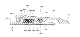
- this kind of sealing material there is one used for a slip-on type separation preventing pipe joint 271 as shown in FIG.
- this pipe joint 271 an insertion opening 275 formed at the end of the other pipe 274 is inserted into a receiving opening 273 formed at the end of one pipe 272 connected to each other.
- a sealing material placement recess 276 is formed on the inner periphery of the receiving port 273, and a rubber-made annular sealing material 277 is placed in the sealing material placement recess 276.
- a lock ring groove 278 is formed on the back side of the sealing material arranging recess 276.
- a lock ring 279 is attached to the lock ring groove 278.
- An elastic member 280 for centering the lock ring 279 is disposed between the outer periphery of the lock ring 279 and the bottom surface of the lock ring groove 278.
- a protrusion 281 that can be engaged with the lock ring 279 from the back side of the receiving port is formed on the outer periphery of the distal end portion of the insertion port 275.
- a fitting groove 282 is formed in the peripheral surface 284 of the sealing material disposing recess 276.
- the sealing material 277 includes a heel portion 283 that is fitted and engaged in the fitting groove 282, and a valve portion 285 that is compressed between the peripheral surface 284 and the outer peripheral surface of the insertion port 275 to generate a seal surface pressure. ing.
- the valve portion 285 has first to third convex portions 286 to 288.
- the first convex portion 286 is formed on the outer peripheral portion of the valve portion 285 and protrudes outward in the radial direction A. Further, the second convex portion 287 is formed on the back end side of the valve portion 285.
- the third convex portion 288 is formed on the inner peripheral portion of the valve portion 285 and protrudes inward in the radial direction A.
- the inner diameter of the third convex portion 288 is set smaller than the outer diameter of the insertion opening 275.
- a tapered portion 289 that gradually decreases in diameter from the inner circumference of the heel portion 283 toward the third convex portion 288 is formed.
- the heel portion 283 is fitted into the fitting groove 282 and the insertion port 275 is inserted into the receiving port 273, whereby the third convex portion 288 is expanded in diameter.
- the valve portion 285 is sandwiched between the inner peripheral surface of the receiving port 273 and the outer peripheral surface of the insertion port 275.
- the space between the first convex portion 286 and the third convex portion 288 is compressed in the radial direction A.
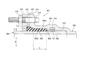
- FIG. 30 there is a pipe joint 301 of a GX-shaped deformed pipe for joining pipes made of cast iron.
- this pipe joint 301 an insertion opening 305 formed at the end of the second pipe 304 is inserted into a receiving opening 303 formed at the end of the first pipe 302 to be joined together.
- a peripheral wall portion 306 that protrudes inward in the radial direction is formed on the inner periphery of the inner portion of the receiving port 303 over the entire periphery.
- a sealing material insertion space 308 is formed over the entire circumference between the outer peripheral surface 305a of the insertion port 305 and the inner peripheral surface 303a of the reception port 303 between the opening end surface 307 of the reception port 303 and the peripheral wall portion 306.
- An annular sealing material 309 that seals between the outer peripheral surface 305 a of the insertion port 305 and the inner peripheral surface 303 a of the receiving port 303 is inserted into the sealing material insertion space 308.
- a lock ring groove 310 is formed on the inner side of the peripheral wall portion 306 over the entire circumference.
- the lock ring groove 310 is provided with a lock ring 311 which is divided in the circumferential direction.
- a protrusion 312 that can be engaged with the lock ring 311 from the back side of the receiving port is formed on the outer periphery of the distal end portion of the insertion port 305 over the entire periphery.
- a push ring 313 is fitted on the insertion opening 305 so as to face the opening end surface 307 of the receiving opening 303 from the outside.
- the pusher wheel 313 pushes the sealing material 309 into the back side of the receiving port 303, and is fastened to the flange portion 316 of the receiving port 303 by a plurality of T-head bolts 314 and nuts 315.
- the pusher wheel 313 includes a pressing surface 317 that abuts against an end of the sealing material 309 and a protrusion 318.
- the protrusion 318 maintains the interval A from the pressing surface 317 to the opening end surface 307 of the receiving port 303 at a predetermined interval by contacting the opening end surface 307 of the receiving port 303.
- the lock ring 311 is fitted into the lock ring groove 310, and further, the insertion port 305 is fitted with the sealing material 309 and the push ring 313 fitted to the insertion port 305.
- the insertion port 305 is inserted into the receiving port 303 until the protruding portion 112 passes through the inner periphery of the lock ring 311 to the inner side of the receiving port 303.
- the sealing material 309 is inserted into the sealing material insertion space 308 from the opening end surface 307 of the receiving port 303, and the presser wheel 313 is fastened to the flange portion 316 of the receiving port 303 using the T-head bolt 314 and the nut 315.
- the pusher wheel 313 moves along the tube axis in the pushing direction B, so that the pushing surface 317 of the pushing wheel 313 pushes the sealing material 309 in the pushing direction B, and the sealing material 309 It is pushed into the sealing material insertion space 308.
- the protrusion 318 of the pusher wheel 313 comes into contact with the opening end surface 307 of the receiving port 303 to prevent the pusher wheel 313 from moving in the pushing direction B.
- the nut 315 is stopped from being tightened, and the pusher wheel 313 is stopped.
- the distance A from the pressing surface 317 to the opening end face 107 of the receiving port 303 is maintained at a predetermined distance.
- the back end portion of the sealing material 309 does not reach the peripheral wall portion 306, and a slight space 320 is formed between the back end portion of the sealing material 309 and the peripheral wall portion 306.
- the sealing material 309 is in the compression region C. Compressed in the radial direction D, the water tightness (sealability) between the inner peripheral surface 303a of the receiving port 303 and the outer peripheral surface 305a of the insertion port 305 is maintained.
- the magnitude of E is not constant and varies slightly. That is, when the inner diameter dimension of the receiving port 303 is on the maximum side of the manufacturing tolerance and the outer diameter dimension of the insertion port 305 is on the minimum side of the manufacturing tolerance, the gap E is maximized. On the other hand, when the inner diameter dimension of the receiving port 303 is on the minimum side of the manufacturing tolerance and the outer diameter dimension of the insertion port 305 is on the maximum side of the manufacturing tolerance, the gap E is minimized.
- the operator cannot visually recognize from the outside that the back end portion of the sealing material 309 has reached the peripheral wall portion 306 as described above, and therefore, the protrusion 318 of the pusher wheel 313 is received by the receiving port 303.
- the nut 315 is forcibly tightened in an attempt to make contact with the open end surface 307.
- an excessive force is applied to the sealing material 309 and the push ring 313, and there is a possibility that the joining of the tubes 302 and 304 may be hindered.
- the present invention provides a sealing material and a joint that can reduce the maximum insertion force required to insert the insertion port into the receiving port and can improve the water tightness between the receiving port and the insertion port.
- a press ring and a joint capable of bringing the contact portion of the press ring into contact with the receiving port and joining the flow path forming members such as pipes without hindrance, and further capable of suppressing the length of the receiving port, and
- the purpose is to provide a valve.
- the first invention is used for a joint in which an insertion opening formed at the end of one pipe is inserted into a receiving opening formed at the end of one pipe connected to each other.
- An annular sealing material made of elastic material A heel portion fitted in a fitting portion formed in the receiving port, and a valve portion sandwiched between the inner peripheral surface of the receiving port and the outer peripheral surface of the insertion port,
- the valve portion has first to third convex portions, The first convex portion is formed on the outer peripheral portion of the valve portion and protrudes outward in the radial direction.
- the second convex portion is formed on the back end side of the valve portion, A tapered portion is formed which is reduced in diameter from the inner periphery of the heel portion toward the inner periphery of the second convex portion,
- the third convex portion is formed in the tapered portion and protrudes inward in the radial direction, and is located between the heel portion and the second convex portion in the tube axis direction,
- the inner diameter of the third convex portion is smaller than the outer diameter of the insertion opening and larger than the inner diameter of the second convex portion,
- the first dimension from the first convex part to the third convex part in the inclination direction opposite to the inclination direction of the taper part is from the outer periphery of the first convex part to the inner periphery of the second convex part in the radial direction.
- the heel portion of the sealing material is fitted into the fitting portion in the receiving port, and the insertion port is inserted into the receiving port.
- the distal end portion of the insertion port abuts on the third convex portion of the sealing material and pushes the third convex portion in the depth direction of the receiving port, whereby the second convex portion is expanded in diameter and third.
- the convex part is drawn in the back direction of the receptacle.
- a tensile force in the tube axis direction is generated in the valve portion, and the valve portion is stretched in the depth direction of the receiving port, so that the first dimension is reduced and the compression allowance (compression amount) of the valve portion in the radial direction is reduced.
- the distal end portion of the insertion port compresses the valve portion of the sealing material while passing through the third convex portion, and at this time, the space between the first convex portion and the third convex portion is compressed in the radial direction.
- the sealing material has a first dimension from the first convex part to the third convex part that is smaller than a second dimension from the outer periphery of the first convex part to the inner periphery of the second convex part. The compression allowance of the valve part in the radial direction is reduced, thereby reducing the maximum insertion force.
- the space between the first convex portion and the third convex portion is radially compressed between the inner peripheral surface of the receiving port and the outer peripheral surface of the insertion port, so that it is between the receiving port and the insertion port. Therefore, the water tightness between the receiving port and the insertion port can be improved.
- concave portions are formed between the heel portion and the first convex portion and between the heel portion and the third convex portion, respectively.
- the tensile force generated in the valve portion when the insertion port is inserted into the receiving port and the third convex portion is pushed in the depth direction of the receiving port at the distal end portion of the insertion port is reduced, and the second convex portion Can be easily expanded.
- tip part of an insertion port can pass a valve
- the third invention is a joint provided with the sealing material according to the first invention or the second invention,
- the heel part of the sealing material is fitted into the fitting part in the receiving port,
- the insertion port is inserted into the receiving port,
- the valve portion of the sealing material is sandwiched between the inner peripheral surface of the receiving port and the outer peripheral surface of the insertion port.
- the insertion port formed in the second flow path forming member is inserted into the receiving port formed in the first flow path forming member joined to each other, On the inner periphery of the back part of the receiving port, a peripheral wall part protruding inward in the radial direction is formed, A sealing material insertion space is formed between the outer peripheral surface of the insertion port and the inner peripheral surface of the reception port between the opening end surface of the reception port and the peripheral wall portion, Used for joints in which an annular seal material is inserted in the seal material insertion space, A push ring that is externally fitted to the insertion opening and faces the opening end face of the receiving opening from the outside, and moves in the pushing direction along the axis of the flow path forming member by the pushing member to push the sealing material into the sealing material insertion space.
- a pressing surface that contacts the end of the sealing material; a contact portion that maintains a predetermined distance from the pressing surface to the opening end surface of the receiving port by contacting the receiving port; and a part of the sealing material pressed by the pressing surface Has an escape portion that can escape.
- the insertion port is inserted into the receiving port in a state where the sealing material and the push ring are fitted on the insertion port. Thereafter, the sealing material is inserted into the sealing material insertion space from the opening end face of the receiving port, and the pusher wheel is moved in the pushing direction by the pushing member. Thereby, the pressing surface of the push wheel presses the sealing material in the pressing direction, and the sealing material is pressed into the sealing material insertion space.
- the gap between the inner peripheral surface of the receiving port and the outer peripheral surface of the insertion port is reduced, and before the contact portion of the press ring contacts the receiving port, the inner end of the sealing material reaches the peripheral wall portion, Even when the seal material cannot be pushed into the seal material insertion space any more, the push wheel is continuously moved in the push direction by the push member, so that one of the seal materials pressed by the push surface of the push wheel. Since the part escapes into the escape part, the contact part of the push ring can be brought into contact with the receiving port without difficulty, and the flow path forming members are hindered without applying excessive force (excessive force) to the sealing material or push ring. In addition to being able to be joined, it is possible to prevent the receiving port from becoming long.
- the escape portion is a concave-shaped portion in which the opening end surface side of the opposite receiving port is opened, is formed on the outer side in the radial direction than the pressing surface, and is formed over the entire circumference. It is depressed in the direction of pulling out the insertion slot.
- the escape portion has a centering portion that guides the press wheel in the radial direction so that the center of the press wheel is aligned with the axis of the flow path forming member.
- the escape portion has an inner peripheral side wall surface and an outer peripheral side wall surface that is a centering portion, These inner peripheral side wall surface and outer peripheral side wall surface are opposed to each other in the radial direction, The outer peripheral side wall surface is inclined so as to decrease in diameter toward the back of the escape portion, The outer peripheral side wall surface is guided in the radial direction by being in sliding contact with the end portion of the sealing material.
- the outer peripheral side wall surface of the escape portion is in sliding contact with the end portion of the sealing material, so that the push ring is guided in the radial direction, and the center of the push ring forms a flow path. Aligned with the axis of the member.
- the eighth aspect of the invention is a joint provided with the push wheel according to any one of the fourth aspect to the seventh aspect of the invention,
- the first and second flow path forming members are pipes,
- the press ring is fitted to the insertion opening and faces the opening end face of the receiving opening from the outside,
- the push member moves the push ring along the tube axis in the push direction so that the push ring pushes the seal material into the seal material insertion space until the contact portion contacts the receiving port.
- the contact portion of the push wheel can be brought into contact with the receiving port, and the tubes can be joined without any trouble, and further, it is possible to prevent the receiving port from becoming long. Mouth extension and tube mass increase are suppressed.
- a ninth aspect of the present invention is a joint provided with the press wheel according to any one of the fourth to seventh aspects of the invention
- One of the first and second flow path forming members is a valve and the other is a pipe
- the press ring is fitted to the insertion opening and faces the opening end face of the receiving opening from the outside,
- the push member moves the push ring along the tube axis in the push direction so that the push ring pushes the seal material into the seal material insertion space until the contact portion contacts the receiving port.
- the contact portion of the push wheel can be brought into contact with the receiving port, the valve and the pipe can be joined without any trouble, and further, it is possible to prevent the receiving port from becoming long.
- the extension of the mouth and the increase in mass of the tube or valve are suppressed.
- the tenth aspect of the present invention is a valve connected to a pipe by the joint according to the ninth aspect of the present invention, Having a valve box and a valve body for opening and closing a flow path formed in the valve box,
- the valve box is provided with at least one of a receiving port and an insertion port.
- the present invention it is possible to reduce the maximum insertion force required when inserting the insertion opening into the receiving opening, and to improve the water tightness between the receiving opening and the insertion opening.
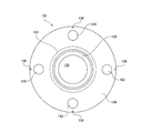
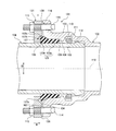
- FIG. 13 is a view on arrow XX in FIG. 12. It is sectional drawing which shows the procedure which attaches the push ring of a joint similarly. It is sectional drawing which shows the procedure which attaches the push ring of a joint similarly. It is sectional drawing which shows the procedure which attaches the push ring of a joint similarly. It is sectional drawing which shows the procedure which attaches the push ring of a joint similarly.
- FIG. 6 is a cross-sectional view showing a state in the middle of attachment of the press ring when the clearance between the receiving port and the insertion port is small in the joint.
- FIG. 6 is a cross-sectional view showing a state after the press ring has been attached when the clearance between the receiving port and the insertion port is small in the joint. It is a front view of the push ring in the 3rd Embodiment of this invention.
- FIG. 20 is a view on arrow XX in FIG. 19.
- FIG. 20 is a view on arrow YY in FIG. 19. It is sectional drawing of the joint which showed the location of the pressing surface of a press ring in the cross section similarly. It is sectional drawing of the joint which showed the location of the escape part of the push ring in the cross section similarly.
- FIG. 6 is a cross-sectional view showing a state in the middle of attachment of the press ring when the clearance between the receiving port and the insertion port is small in the joint.
- FIG. 6 is a cross-sectional view showing a state after the press ring has been attached when the clearance between the receiving port and the insertion port is small in the joint.
- reference numeral 1 denotes a push-on type detachment prevention pipe joint, and the other receiving port 3 formed at the end of one pipe 2 connected to the other is connected to the other.
- An insertion opening 5 formed at the end of the tube 4 is inserted.
- a recess 6 for sealing material placement and a lock ring groove 7 located on the back side of the recess 6 for sealing material placement are formed on the inner peripheral surface of the receiving port 3 over the entire circumference.
- the lock ring groove 7 is fitted with a lock ring 8 which is divided by one in the circumferential direction.
- an elastic biasing means 9 such as a rubber ring for fixing the lock ring 8 is disposed.
- a back end surface 11 in the radial direction A is formed inside the receiving port 3 spaced from the lock ring groove 7 to the back side.
- the insertion opening 5 has a protrusion 12 that can be engaged with the lock ring 8 from the back side of the receiving port on the outer periphery of the distal end portion over the entire periphery.
- a fitting groove 14 (an example of a fitting portion) is formed on the entire peripheral surface of the sealing material arranging recess 6 over the entire circumference.
- Between the receiving port 3 and the insertion port 5 is made of rubber (an example of an elastic material) and sealed with an annular sealing material 16 over the entire circumference.
- the sealing material 16 is configured as follows.
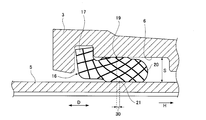
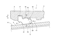
- FIG. 2 shows a single cross-sectional structure of the sealing material 16 that is not attached to the pipe joint 1.
- the sealing material 16 includes a heel portion 17 that is fitted in the fitting groove 14, and a valve portion 18 that is sandwiched between the inner peripheral surface of the receiving port 3 (the peripheral surface of the sealing material disposing recess 6) and the outer peripheral surface of the insertion port 5. And have.
- the heel portion 17 is an annular member having a rectangular cross-sectional shape (cross-sectional shape perpendicular to the circumferential direction).
- the valve portion 18 is an annular member, and includes first to third valves 19 to 21 (an example of first to third convex portions) and first to fourth concave portions 23 to 26. Yes.
- bulb 19 has circular arc shape, is formed in the outer peripheral part of the valve
- the second valve 20 has an arc shape, is formed over the entire periphery of the receiving end of the valve portion 18 and protrudes obliquely toward the center of the tube.
- the valve portion 18 is formed with a tapered portion 28 that gradually decreases in diameter from the inner periphery of the heel portion 17 toward the inner periphery of the second valve 20.
- the third valve 21 has an arc shape, is formed over the entire circumference of the tapered portion 28, protrudes inward in the radial direction A, and in the tube axis direction D, the heel portion 17, the second valve 20, Located between. Further, the inner diameter E1 of the third valve 21 is smaller than the outer diameter E2 of the insertion port 5 and larger than the inner diameter E3 of the second valve 20.
- the first valve 19 to the third valve 21 in the inclination direction opposite to the inclination direction G of the tapered portion 28 that is, the direction closer to the center of the tube toward the front side of the receiving port 3.
- the dimension B is smaller than the second dimension C from the outer periphery of the first valve 19 to the inner periphery of the second valve 20 in the radial direction A.
- the first to fourth recesses 23 to 26 each have an arc shape and are formed in the valve portion 18 over the entire circumference.
- the 1st recessed part 23 is between the heel part 17 and the 1st valve
- the 2nd recessed part 24 is between the 1st valve
- the 3rd recessed part 25 is the 1st valve
- the second recess 20 is formed between the second valve 20 and the third valve 21
- the protrusion 12 of the insertion port 5 compresses the valve portion 18 in the radial direction A while passing through the inside of the third valve 21.
- the positional relationship between the first to third valves 19 to 21 is close to a triangle having the third valve 21 as an apex inside the radial direction A, and the first valve 19 and the third valve 21 Is compressed in the radial direction A.
- the first dimension B is smaller than the second dimension C.
- both the pipes 2 and 4 are joined by the protrusion 12 of the insertion port 5 passing through the inside of the lock ring 8 toward the back of the receiving port.
- the first valve is formed between the inner peripheral surface of the receiving port 3 (the peripheral surface of the sealing material disposing recess 6) and the outer peripheral surface of the insertion port 5. Since the space between 19 and the third valve 21 is compressed in the radial direction A, the watertightness between the receiving port 3 and the insertion port 5 is maintained. It is possible to improve water tightness.
- FIG. 4 is a graph showing the relationship between the insertion amount of the insertion slot 5 with respect to the receiving slot 3 and the insertion force.
- the 1st graph M1 shown as the continuous line corresponds to this 1st Embodiment, and has the two peaks P1 and P2 from which insertion force becomes the maximum.
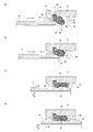
- the peak P1 of the first insertion force indicates that the distal end portion of the insertion port 5 passes the third valve 21 in the depth direction J of the receiving port in the joining procedure (2) shown in FIG. This occurs when the valve portion 18 is extended in the depth direction J of the receiving port by being pushed in.
- the peak P2 of the second insertion force is obtained when the protrusion 12 of the insertion port 5 passes inside the third valve 21 in the joining procedure (3) shown in FIG. This occurs when the valve portion 18 is compressed in the radial direction A.
- the valve portion 18 when the insertion port 5 is inserted into the receiving port 3, the valve portion 18 is mainly stretched in the depth direction J of the receiving port, and the valve portion 18 is mainly used in the diameter. Since the phenomenon of being compressed in the direction A occurs with a slight shift in time according to the insertion amount of the insertion opening 5, the insertion force of the insertion opening 5 with respect to the reception opening 3 is dispersed into the two peaks P1 and P2. Reduced.
- the second graph M2 indicated by a dotted line is the conventional graph shown in FIGS. 28 and 29 and has one peak P.
- the phenomenon that the valve portion 285 is stretched mainly in the depth direction of the receiving port, and the phenomenon that the valve portion 285 is compressed mainly in the radial direction A It occurs almost simultaneously according to the insertion amount of the insertion opening 275. For this reason, the insertion force of the insertion port 5 with respect to the receiving port 3 is concentrated in one peak P, without being disperse
- the above description shows the case where the gap S between the inner periphery of the receiving port 3 and the outer periphery of the insertion port 5 is standard (that is, when the gap S has a specified dimension), as shown in FIG.
- the position of the third valve 21 hardly shifts to the insertion direction H side with respect to the position of the first valve 19. Therefore, the position of the first valve 19 in the tube axis direction D and the third valve The amount of deviation 30 from the position 21 is slight.
- the inner diameter dimension of the receiving port 3 is the minimum side of the manufacturing tolerance and the outer diameter dimension of the insertion port 5 is the maximum side of the manufacturing tolerance, as shown in FIG. Is minimized.
- the hooking margin (hanging amount) between the third valve 21 and the distal end portion of the insertion port 5 increases, so that the gap S shown in FIGS. 3 and 5 is a standard case.
- the third valve 21 is pulled further into the receiving port 3.
- the 1st dimension B (refer FIG. 2) is further reduced, and the compression margin of the valve
- the gap S is maximized as shown in FIG. Become.
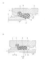
- the diameter of the second valve 20 is expanded by the insertion port 5 when the pipes 2 and 4 are joined.
- the diameter amount is smaller than the diameter expansion amount when the gap S is standard, and as shown in FIG. 7B, the first valve 19 abuts against the inner peripheral surface of the receiving port 3, and the second valve 20 and the third valve 21 are in contact with the outer peripheral surface of the insertion slot 5, the space between the first valve 19 and the second and third valves 20, 21 is compressed in the radial direction A.
- water tightness between the receiving port 3 and the insertion port 5 can be ensured.
- an external force acts on the pipe joint 1 and the pipes 2 and 4 in an earthquake or the like, and the pipe joint 1 may be bent or the pipes 2 and 4 may be deformed flat due to such an external force.
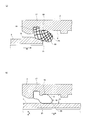
- the first valve 19 contacts the inner peripheral surface of the receiving port 3 and the third valve 21. Comes into contact with the outer peripheral surface of the insertion slot 5.
- the pushing force F1 acts on the second valve 20 to deform the valve portion 18, and the pushing force F2 proportional to the pushing force F1 by the self-sealing action. Occurs in the radial direction A of the valve portion 18, thereby improving water tightness.
- the insertion opening 5 is inclined with respect to the receiving opening 3, and the gap S between the inner periphery of the receiving opening 3 and the outer periphery of the insertion opening 5 is an opening end portion than the back side of the receiving opening 3. Even when the third valve 21 is enlarged on the side, the third valve 21 is reliably pressed against the outer peripheral surface of the insertion port 5 by the inward pressing force F2 in the radial direction. It is possible to prevent insufficient watertightness with the surface.
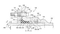
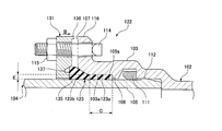
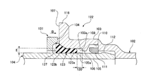
- the joint 122 in the second embodiment includes a first pipe 102 (an example of a first flow path forming member) and a second pipe 104 (second flow path formation). It is a pipe joint which joins an example of a member.
- an insertion port 105 formed at the end of the second tube 104 is inserted into a receiving port 103 formed at the end of the first tube 102 to be joined to each other.
- a peripheral wall portion 106 that protrudes inward in the radial direction is formed on the inner periphery of the inner portion of the mouth 103 over the entire periphery.
- a sealing material insertion space 108 is formed over the entire circumference between the outer peripheral surface 105 a of the insertion port 105 and the inner peripheral surface 103 a of the receiving port 103 between the opening end surface 107 of the receiving port 103 and the peripheral wall portion 106.
- An annular sealing material 123 that seals between the outer peripheral surface 105 a of the insertion port 105 and the inner peripheral surface 103 a of the receiving port 103 is inserted into the sealing material insertion space 108.
- a region where the inner peripheral surface 103a of the receiving port 103 and the outer peripheral surface 105a of the insertion port 105 face each other in parallel is defined as a compression region C.
- the inner peripheral surface 103 a of the receiving port 103 has a tapered portion 103 b between the opening end surface 107 and the compression region C.
- the tapered portion 103 b increases in diameter from the back side of the receiving port 103 to the opening end surface 107.
- a lock ring groove 110 is formed over the entire circumference on the back side of the peripheral wall portion 106.
- the lock ring groove 110 is provided with a lock ring 111 that is divided in the circumferential direction.
- the insertion port 105 has a protrusion 112 that can be engaged with the lock ring 111 from the back side of the receiving port on the outer periphery of the distal end portion.
- a push ring 131 that pushes the sealing material 123 into the back side of the receiving port 103 is externally fitted to the insertion port 105 and faces the opening end surface 107 of the receiving port 103 from the outside.
- the sealing material 123 is made of an elastic material such as rubber and is formed in an annular shape.
- the cross-section of the sealing material 123 is such that a circular tip portion 123a formed in a circle at a position that becomes a tip when press-fitted, and a portion connected to the circular tip portion 123a are thin-walled, and the side closer to the push wheel 131 is thicker.
- the trapezoidal base 123b is integrally formed.
- the push wheel 131 is fastened to the flange portion 116 of the receiving port 103 by a plurality of T-head bolts 114 (an example of a pushing member) and nuts 115 (an example of a pushing member). It can be moved in the pushing direction B along the tube axis 119 (see FIG. 16).
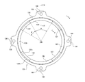
- the pusher wheel 131 contacts the central opening 132 through which the insertion hole 105 is inserted, the plurality of bolt insertion holes 133, the pusher wheel end surface 134 facing the opening end surface 107 of the receiving port 103, and the end surface of the base 123 b of the sealing material 123.
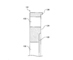
- the distance A (see FIG. 10) from the pressing surface 135 to the opening end surface 107 of the receiving port 103 is maintained at a predetermined interval by contacting the pressing surface 135 that contacts and presses the sealing material 123 and the opening end surface 107 of the receiving port 103. It has a plurality of protrusions 136 (an example of a contact portion) and an escape portion 137 into which the base portion 123b of the sealing material 123 pressed by the pressing surface 135 can escape.
- the protrusion 136 is formed outside the bolt insertion hole 133 in the radial direction D. Further, the pressing surface 135 enters the drawing direction F of the insertion opening 105 from the pusher wheel end surface 134, and is formed over the entire circumference on the inner peripheral side from the pusher wheel end surface 134. Thereby, a step in the tube axis direction is formed between the pressing surface 135 and the wheel end surface 134.
- the escape portion 137 is a concave-shaped portion (groove-shaped portion) in which the opening end surface 107 side of the receiving port 103 facing the opening 103 is opened, and is outside in the radial direction D from the pressing surface 135 and in the radial direction D from the pusher wheel end surface 134. Is formed over the entire circumference, and is recessed from the pressing surface 135 in the drawing direction F of the insertion opening 105.
- the escape portion 137 has an inner peripheral side wall surface 137a, an outer peripheral side wall surface 137b, and a rear surface 137c.
- the inner peripheral side wall surface 137a and the outer peripheral side wall surface 137b are opposed to each other in the radial direction D, and the inner surface 137c is It is formed between the back end portion of the side wall surface 137a and the back end portion of the outer peripheral side wall surface 137b.
- the outer peripheral side wall surface 137b is an example of a centering portion that guides the pusher wheel 131 in the radial direction D so that the center of the pusher wheel 131 is aligned with the tube shaft center 119 (see FIG. 16, an example of the shaft center of the flow path forming member). Inclined so that the diameter of the escape portion 137 decreases.
- the width G of the pressing surface 135 in the radial direction D shown in FIG. 12 is set to a dimension of about 30 to 70% of the width H of the base 123b of the sealing material 123 shown in FIG.
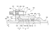
- the lock ring 111 When joining the pipes 102 and 104, first, as shown in FIG. 14, the lock ring 111 is fitted into the lock ring groove 110 in the receiving port 103, and the sealing material 123 and the push ring 131 are removed from the insertion port 105. In the fitted state, the insertion port 105 is inserted into the receiving port 103 until the protrusion 112 of the insertion port 105 passes through the inner periphery of the lock ring 111 to the back side of the receiving port 103.
- the circular tip 123a of the sealing material 123 is brought into contact with the tapered portion 103b of the receiving port 103, and the T-head bolt 114 is connected to the bolt through hole 124 of the flange portion 116 of the receiving port 103 and the bolt insertion hole 133 of the press ring 131. Insert.
- the center of the pusher wheel 131 rises and is aligned with the tube axis 119, and the pusher wheel 131 is automatically centered. Thereby, it is possible to save labor for the operator to lift the push wheel 131 and move it in the radial direction D for centering.
- the protrusion 136 of the pusher wheel 131 comes into contact with the opening end surface 107 of the receiving port 103, thereby preventing the pusher wheel 131 from moving in the pushing direction B.
- the nut 115 is tightened. Is stopped, the interval A from the pressing surface 135 of the push wheel 131 to the opening end surface 107 of the receiving port 103 is maintained at a predetermined interval.
- the back end portion of the sealing material 123 does not reach the peripheral wall portion 106, and a slight space 120 is formed between the back end portion of the sealing material 123 and the peripheral wall portion 106.
- the circular tip 123 a of the sealing material 123 is compressed in the radial direction D in the compression region C, whereby the inner peripheral surface 103 a of the receiving port 103 and the outer peripheral surface 105 a of the insertion port 105. The water tightness between them is maintained.
- the joint 122 shown in FIG. 9 and FIG. 16 shows a case where a sufficiently large gap E is secured between the inner peripheral surface 103 a of the receiving port 103 and the outer peripheral surface 105 a of the insertion port 105. ing.
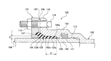
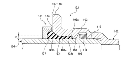
- the gap E is reduced due to manufacturing tolerances, before the protrusion 136 of the pusher wheel 131 contacts the opening end surface 107 of the receiving port 103, the back end of the sealing material 123 is The portion may reach the peripheral wall portion 106, and the sealing material 123 may not be pushed into the sealing material insertion space 108 any more.
- the base 123 b of the sealing material 123 pressed by the press surface 135 of the push wheel 131 is used.
- the end portion enters the escape portion 137.
- the protrusion 136 of the push wheel 131 can be reasonably brought into contact with the opening end surface 107 of the receiving port 103.
- the pipes 102 and 104 can be joined without any trouble without applying an excessive force (excessive force) to the push wheel 131, and the receiving port 103 can be prevented from becoming long, thereby suppressing an increase in cost. be able to.
- a predetermined area surrounded by the pressing surface 135 of the push wheel 131, the escape portion 137, the inner peripheral surface 103a of the receiving port 103, the outer peripheral surface 105a of the insertion port 105, and the peripheral wall portion 106 is shown.
- the volume of the gap region 140 is V1 and the volume of the sealing material 123 is V2
- the volume V1 of the predetermined gap region 140 is not less than the volume V2 of the sealing material 123 (that is, V1 ⁇ V2).
- the size of the insert portion 137 is set.
- the volume V1 is obtained by multiplying the cross-sectional area of the gap region 140 by the circumference of the centroid of the gap region 140
- the volume V2 is obtained by multiplying the cross-sectional area of the seal material 123 by the circumference of the centroid of the seal material 123. Is required.
- the width G of the pressing surface 135 (see FIG. 12) is set to a size of about 30 to 70% of the width H (see FIG. 11) of the base 123b of the sealing material 123.
- the dimension is set to be smaller than about 30%, the force received by the end surface of the base 123b of the sealing material 123 from the pressing surface 135 of the press wheel 131 may be too small. There is a possibility that the force to push in the pushing direction B is insufficient.
- the width G is set to a size larger than about 70% of the width H, the outer diameter of the pressing surface 135 of the press wheel 131 increases and the outer diameter of the escape portion 137 is constant. Since the inner diameter of the escape portion 137 increases, the volume (internal volume) of the escape portion 137 decreases, and when the gap E is small, the escape amount of the sealing material 123 entering the escape portion 137 is insufficient. There is a possibility that it is difficult to bring the protrusion 136 of the push wheel 131 into contact with the opening end surface 107 of the receiving port 103.
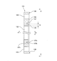
- the pressing surface 135 and the escape portion 137 are formed over the entire circumference of the press wheel 131, but the third embodiment described below. Then, as shown in FIGS. 19 to 21, the pressing surface 135 and the escape portion 137 are each divided into a plurality of parts in the circumferential direction of the press wheel 131.
- each escape portion 137 has an outer peripheral side wall surface 137 b and a rear surface 137 c, and the inner peripheral side communicates with the central opening 132 of the push wheel 131.
- the outer peripheral side wall surface 137 b is an example of a centering portion that guides the push wheel 131 in the radial direction D, and is inclined so as to reduce in diameter toward the back of the escape portion 137. Yes.
- the protrusion 136 of the pusher wheel 131 comes into contact with the opening end surface 107 of the receiving port 103 to prevent the pusher wheel 131 from moving in the pushing direction B.
- the nut 115 is tightened.
- the interval A from the pressing surface 135 of the push wheel 131 to the opening end surface 107 of the receiving port 103 is maintained at a predetermined interval.
- the back end portion of the sealing material 123 does not reach the peripheral wall portion 106, and a slight space 120 is formed between the back end portion of the sealing material 123 and the peripheral wall portion 106.
- the joint 122 shown in FIGS. 22 and 23 shows a case where a sufficiently large gap E is secured between the inner peripheral surface 103 a of the receiving port 103 and the outer peripheral surface 105 a of the insertion port 105. ing.
- the gap E becomes small due to manufacturing tolerances
- the portion may reach the peripheral wall portion 106, and the sealing material 123 may not be pushed into the sealing material insertion space 108 any more.
- the end portion of the base 123b of the sealing material 123 enters the escape portion 137 as shown in FIG.
- the protrusion 136 of the push wheel 131 can be reasonably brought into contact with the opening end surface 107 of the receiving port 103.
- the pipes 102 and 104 can be joined without any trouble without applying an excessive force (excessive force) to the push wheel 131, and the receiving port 103 can be prevented from becoming long, thereby suppressing an increase in cost. be able to.
- the outer peripheral side wall surface 137b of the escape portion 137 is in sliding contact with the outer peripheral end corner portion 123c of the base portion 123b of the sealing material 123.
- the push wheel 131 is guided in the radial direction D and automatically centered. Thereby, it is possible to save labor for the operator to lift the push wheel 131 and move it in the radial direction D for centering.
- the pressing wheel 131 is provided with the pressing surface 135 and the escape portion 137 at four locations, respectively, but is not limited to four locations, and other than the four locations. A plurality of locations may be provided.
- the first pipe 102 is given as an example of the first flow path forming member, and the second flow path forming member is taken as an example.
- tube 104 was mentioned and the pipe joint was mentioned as the joint 122
- the joint 122 is not limited to the joint of the pipes 102 and 104, For example, like 4th Embodiment demonstrated below. Further, a joint for joining the valve and the pipe may be used.
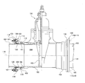
- the joint 150 in the fourth embodiment joins a soft seal gate valve 151 (an example of a first flow path forming member) and a pipe 152 (an example of a second flow path forming member). It is a joint to do.
- the soft seal gate valve 151 includes a valve box 153 and a valve body 155 that opens and closes a flow path 154 formed in the valve box 153.
- the valve box 153 is provided with a pair of receiving ports 103 serving as fluid inlets and outlets. Further, an insertion port 105 is provided at one end of the tube 152, and the insertion port 105 is inserted into the receiving port 103 to constitute a joint 150 between the gate valve 151 and the tube 152. Since the structure of the joint 150 is the same as that of the joint 122 of the second or third embodiment described above, detailed description thereof is omitted.
- the gate valve 151 is used as an example of the first flow path forming member.
- a valve other than the gate valve may be used.
- the gate valve 151 is given as an example of the first flow path forming member and the pipe 152 is given as an example of the second flow path forming member.
- the pipe 152 may be given as an example of one flow path forming member, and the gate valve 151 may be given as an example of a second flow path forming member.
- the receiving port 103 is provided at one end of the tube 152, and the pair of insertion ports 105 are provided in the valve box 153 of the gate valve 151.
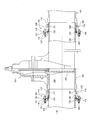
- the valve box 153 is provided with a pair of receiving ports 103 as shown in FIG. 26.
- the receiving port 103 and the insertion port 105 may be provided in the box 153.
- the insertion port 105 of one pipe 152 is inserted into the receiving port 103 of the gate valve 151 to configure the joint 150
- the insertion port 105 of the gate valve 151 is inserted into the receiving port 103 of the other tube 156.
- the joint 150 is configured.
- the pusher 131 is provided with a protrusion 136 that is an example of a contact portion.
- a portion provided on the opening end surface 107 of the receiving port 103 and where the push wheel 131 contacts the protrusion of the receiving port 103 may be a contact portion of the push wheel 131.
Landscapes
- Engineering & Computer Science (AREA)
- General Engineering & Computer Science (AREA)
- Mechanical Engineering (AREA)
- Joints With Sleeves (AREA)
- Gasket Seals (AREA)
- Fastening Of Light Sources Or Lamp Holders (AREA)
Priority Applications (7)
| Application Number | Priority Date | Filing Date | Title |
|---|---|---|---|
| US14/408,591 US10018290B2 (en) | 2012-06-25 | 2013-06-11 | Pressing ring, joint, and valve |
| AU2013282067A AU2013282067B2 (en) | 2012-06-25 | 2013-06-11 | Joint and use of a sealing member |
| CN201380031141.3A CN104364570B (zh) | 2012-06-25 | 2013-06-11 | 密封件、压环、接头及阀 |
| EP13809825.6A EP2848850B1 (de) | 2012-06-25 | 2013-06-11 | Verbindung und verwendung eines dichtungsgleids |
| KR1020147035942A KR102020089B1 (ko) | 2012-06-25 | 2013-06-11 | 시일재 및 압륜 및 커플링 및 밸브 |
| EP17000235.6A EP3190327B1 (de) | 2012-06-25 | 2013-06-11 | Pressring, gelenk und ventil |
| US15/987,246 US10738919B2 (en) | 2012-06-25 | 2018-05-23 | Sealing material and joint |
Applications Claiming Priority (4)
| Application Number | Priority Date | Filing Date | Title |
|---|---|---|---|
| JP2012141533A JP5665801B2 (ja) | 2012-06-25 | 2012-06-25 | 押輪および継手および弁 |
| JP2012-141534 | 2012-06-25 | ||
| JP2012-141533 | 2012-06-25 | ||
| JP2012141534A JP5667126B2 (ja) | 2012-06-25 | 2012-06-25 | シール材および管継手 |
Related Child Applications (2)
| Application Number | Title | Priority Date | Filing Date |
|---|---|---|---|
| US14/408,591 A-371-Of-International US10018290B2 (en) | 2012-06-25 | 2013-06-11 | Pressing ring, joint, and valve |
| US15/987,246 Division US10738919B2 (en) | 2012-06-25 | 2018-05-23 | Sealing material and joint |
Publications (1)
| Publication Number | Publication Date |
|---|---|
| WO2014002745A1 true WO2014002745A1 (ja) | 2014-01-03 |
Family
ID=49782910
Family Applications (1)
| Application Number | Title | Priority Date | Filing Date |
|---|---|---|---|
| PCT/JP2013/066013 Ceased WO2014002745A1 (ja) | 2012-06-25 | 2013-06-11 | シール材および押輪および継手および弁 |
Country Status (8)
| Country | Link |
|---|---|
| US (2) | US10018290B2 (de) |
| EP (2) | EP3190327B1 (de) |
| KR (1) | KR102020089B1 (de) |
| CN (2) | CN105065811B (de) |
| AU (1) | AU2013282067B2 (de) |
| MY (1) | MY176920A (de) |
| TW (2) | TWI575177B (de) |
| WO (1) | WO2014002745A1 (de) |
Cited By (3)
| Publication number | Priority date | Publication date | Assignee | Title |
|---|---|---|---|---|
| CN105036043A (zh) * | 2015-08-11 | 2015-11-11 | 玉环县和成铜业有限公司 | 一种酒桶分配器 |
| JP2017180473A (ja) * | 2016-03-28 | 2017-10-05 | 株式会社クボタ | 管継手および管の接合方法 |
| EP4086494A1 (de) * | 2021-05-04 | 2022-11-09 | Geberit International AG | Dichtringanordnung |
Families Citing this family (32)
| Publication number | Priority date | Publication date | Assignee | Title |
|---|---|---|---|---|
| CN103148293B (zh) * | 2009-01-27 | 2015-07-29 | 株式会社久保田 | 管接头 |
| DE102013018344A1 (de) * | 2013-10-31 | 2015-04-30 | GM Global Technology Operations, LLC (n.d. Ges. d. Staates Delaware) | Kupplungseinheit, kupplungseinrichtung, kraftfahrzeug und verfahren |
| JP6441611B2 (ja) * | 2014-08-25 | 2018-12-19 | 三菱日立パワーシステムズ株式会社 | ガスタービンの排気部材及び排気室メンテナンス方法 |
| GB2535145B (en) * | 2015-02-03 | 2017-10-18 | Acergy France SAS | Termination bulkheads for subsea pipe-in-pipe systems |
| US9903515B2 (en) * | 2015-12-09 | 2018-02-27 | Victaulic Company | Seal with lip projections |
| CN109154388B (zh) * | 2016-06-10 | 2021-01-08 | 纳博特斯克有限公司 | 垫片以及阀装置 |
| US11199280B2 (en) | 2017-04-19 | 2021-12-14 | Mueller Intemational, LLC | Joint restraint device |
| US11131412B2 (en) | 2017-04-19 | 2021-09-28 | Mueller International, Llc | Joint restraint device |
| US10677381B2 (en) | 2017-04-19 | 2020-06-09 | Mueller International, Llc | Joint restraint device |
| US10941887B2 (en) | 2017-07-13 | 2021-03-09 | Mueller International Llc | Wide range coupling |
| US11215301B2 (en) | 2017-07-28 | 2022-01-04 | ASC Engineered Solutions, LLC | Pre-assembled coupling assembly with flexible hose adapter |
| US11268638B2 (en) | 2017-07-28 | 2022-03-08 | ASC Engineered Solutions, LLC | Pre-assembled coupling assemblies with pipe fitting |
| CN107461560B (zh) * | 2017-09-26 | 2023-11-28 | 新兴铸管股份有限公司 | 自锚接口 |
| JP7054638B2 (ja) * | 2018-03-16 | 2022-04-14 | 東京エレクトロン株式会社 | シール構造およびシール方法 |
| CN110715125B (zh) * | 2018-07-12 | 2022-06-14 | 三花控股集团有限公司 | 管路转接装置及汽车空调系统 |
| ES2992674T3 (en) * | 2018-08-03 | 2024-12-16 | Saint Gobain Performance Plastics Corp | Ball valve seal |
| US11473705B2 (en) * | 2018-08-22 | 2022-10-18 | Mueller International, Llc | Joint restraint device |
| US10774508B2 (en) | 2018-09-04 | 2020-09-15 | Mueller International, Llc | Hydrant shoe assembly |
| US11162621B2 (en) | 2019-02-04 | 2021-11-02 | Mueller International, Llc | Gland assembly |
| US11566732B2 (en) | 2019-04-17 | 2023-01-31 | Mueller International, Llc | Mechanical joint restraint |
| US11808386B2 (en) | 2019-04-17 | 2023-11-07 | Mueller International, Llc | Mechanical joint restraint |
| US11396965B2 (en) | 2019-07-19 | 2022-07-26 | Mueller International, Llc | Restraint gripper cover with lockout breakaway |
| JP7382203B2 (ja) * | 2019-10-18 | 2023-11-16 | 株式会社クボタ | 管継手および管の接合方法 |
| WO2021102318A1 (en) | 2019-11-22 | 2021-05-27 | Trinity Bay Equipment Holdings, LLC | Reusable pipe fitting systems and methods |
| JP7488129B2 (ja) * | 2020-06-26 | 2024-05-21 | 矢崎総業株式会社 | パッキン |
| TWI755194B (zh) * | 2020-12-09 | 2022-02-11 | 家登精密工業股份有限公司 | 遮蔽治具 |
| USD985741S1 (en) * | 2020-11-06 | 2023-05-09 | Kubota Corporation | Gland for pipe joints |
| JP7602894B2 (ja) | 2020-11-06 | 2024-12-19 | 株式会社クボタ | 管継手、押輪および管の接合方法 |
| US11892107B2 (en) | 2021-04-01 | 2024-02-06 | United States Pipe And Foundry Company, Llc | Compounding locking ring for pipe joints |
| US20250224054A1 (en) * | 2021-09-03 | 2025-07-10 | Kubota Corporation | Gland, pipe joint, and method for joining pipes |
| JP7649720B2 (ja) * | 2021-09-03 | 2025-03-21 | 株式会社クボタ | 押輪、管継手および管の接合方法 |
| JP2025103345A (ja) * | 2023-12-27 | 2025-07-09 | 株式会社クボタ | 受口に挿口を挿入する管継手に用いられるシール材およびこのシール材を用いた管継手 |
Citations (6)
| Publication number | Priority date | Publication date | Assignee | Title |
|---|---|---|---|---|
| JPH0341264A (ja) * | 1989-05-23 | 1991-02-21 | Cie Saint Gobain Pont A Mousson | 密封パッキン、該パッキンを受けるために使用される嵌合部及びこのようにして製造される密封継手 |
| JP2008298155A (ja) * | 2007-05-31 | 2008-12-11 | Kubota Corp | 管継手のシール材およびこのシール材を用いた管継手 |
| JP2010174906A (ja) * | 2009-01-27 | 2010-08-12 | Kubota Corp | 管継手 |
| JP2010286110A (ja) | 2009-05-13 | 2010-12-24 | Kubota Corp | 管継手 |
| JP2011089528A (ja) * | 2009-10-20 | 2011-05-06 | Kubota Corp | 弁と管との継手構造および弁 |
| JP2011099515A (ja) * | 2009-11-06 | 2011-05-19 | Kubota Corp | 弁と管との継手構造および弁 |
Family Cites Families (33)
| Publication number | Priority date | Publication date | Assignee | Title |
|---|---|---|---|---|
| US2735700A (en) * | 1956-02-21 | Packed screw thimble pipe joint | ||
| US2354538A (en) * | 1940-09-27 | 1944-07-25 | Parker Appliance Co | Tube coupling |
| US3547471A (en) * | 1968-02-02 | 1970-12-15 | Christy Metal Products Inc | Pipe coupling |
| JPS5226026B2 (de) | 1971-09-16 | 1977-07-12 | ||
| US3850455A (en) * | 1972-11-17 | 1974-11-26 | Caterpillar Tractor Co | Strain-limiting connector |
| JPS50140752A (de) * | 1974-04-21 | 1975-11-12 | ||
| NL7609192A (nl) * | 1976-08-18 | 1978-02-21 | Wavin Bv | "afdichtlichaam". |
| US4059289A (en) * | 1976-09-10 | 1977-11-22 | Acorn Engineering Company | Waste drain connection |
| FR2554205B1 (fr) | 1983-10-28 | 1986-06-13 | Pont A Mousson | Garniture d'etancheite pour joints de tuyaux en fonte |
| US5114162A (en) * | 1986-11-13 | 1992-05-19 | A-Lok Products, Inc. | Gasket for use in manhole bases and the like |
| DE3803729A1 (de) * | 1988-02-08 | 1989-08-17 | Wedekind Denso Chemie | Steckmuffendichtung fuer betonrohre |
| FR2649177B1 (fr) | 1989-06-28 | 1992-06-19 | Pont A Mousson | Garniture d'etancheite a talon annulaire d'ancrage |
| US5071140A (en) * | 1990-01-02 | 1991-12-10 | Federico Quevedo Del Rio | Self-pressurized gasket seal |
| JPH0799231B2 (ja) | 1991-07-16 | 1995-10-25 | コスモ工機株式会社 | 管継ぎ手 |
| JP2576785Y2 (ja) * | 1993-02-22 | 1998-07-16 | 矢崎総業株式会社 | 防水コネクタの嵌合構造 |
| DE69413233T2 (de) | 1994-10-27 | 1999-04-15 | Victaulic PLC, Hitchin, Hertfordshire | Rohrkupplungen |
| DE9419655U1 (de) * | 1994-12-08 | 1995-02-02 | Kordes Verwaltungs- und Marketing GmbH, 32602 Vlotho | Druckentwässerungsvorrichtung für Abwasser |
| GB2303678B (en) * | 1995-07-26 | 1999-01-20 | Kubota Kk | Separation preventive pipe joint |
| US6126173A (en) * | 1998-01-27 | 2000-10-03 | Poly-Tec Products, Inc. | Extruded gasket for cored manholes |
| US6168210B1 (en) * | 1998-06-19 | 2001-01-02 | M & Fc Holding Company, Inc. | Pipe coupling |
| JP4140869B2 (ja) * | 1998-09-07 | 2008-08-27 | コスモ工機株式会社 | 管継手 |
| JP3061136B1 (ja) * | 1999-08-03 | 2000-07-10 | 株式会社水道技術開発機構 | 管継手 |
| GB2363437B (en) | 2000-06-13 | 2004-08-11 | Glynwed Pipe Systems Ltd | Method and apparatus for coupling pipe ends and a sealing and gripping assembly for the apparatus |
| JP3774889B2 (ja) * | 2002-02-07 | 2006-05-17 | 株式会社川西水道機器 | 管継手用ゴムパッキン |
| JP4039863B2 (ja) | 2002-02-13 | 2008-01-30 | 株式会社クボタ | スペーサおよび管の取扱方法 |
| DK176282B1 (da) | 2005-03-04 | 2007-06-11 | Aage V Kjaers Maskinfabrik As | Rörkobling |
| JP4949061B2 (ja) | 2007-02-13 | 2012-06-06 | コスモ工機株式会社 | 管継手 |
| JP5050662B2 (ja) | 2007-05-31 | 2012-10-17 | パナソニック株式会社 | 燃料改質装置および燃料電池システム |
| CN101436930A (zh) * | 2007-11-16 | 2009-05-20 | 华为技术有限公司 | 一种密钥分发的方法、系统和设备 |
| JP2009250388A (ja) * | 2008-04-09 | 2009-10-29 | Kubota Corp | 管体と管体敷設装置との接続構造および管体敷設装置 |
| CN103148293B (zh) | 2009-01-27 | 2015-07-29 | 株式会社久保田 | 管接头 |
| US8857861B2 (en) * | 2009-10-12 | 2014-10-14 | Mueller International, Llc | Self-restrained pipe joint system |
| JP2011099514A (ja) * | 2009-11-06 | 2011-05-19 | Kubota Corp | 弁と管との継手構造および弁 |
-
2013
- 2013-06-11 MY MYPI2014703938A patent/MY176920A/en unknown
- 2013-06-11 CN CN201510452347.4A patent/CN105065811B/zh active Active
- 2013-06-11 AU AU2013282067A patent/AU2013282067B2/en not_active Expired - Fee Related
- 2013-06-11 WO PCT/JP2013/066013 patent/WO2014002745A1/ja not_active Ceased
- 2013-06-11 EP EP17000235.6A patent/EP3190327B1/de active Active
- 2013-06-11 CN CN201380031141.3A patent/CN104364570B/zh active Active
- 2013-06-11 EP EP13809825.6A patent/EP2848850B1/de active Active
- 2013-06-11 US US14/408,591 patent/US10018290B2/en active Active
- 2013-06-11 KR KR1020147035942A patent/KR102020089B1/ko active Active
- 2013-06-19 TW TW104130438A patent/TWI575177B/zh active
- 2013-06-19 TW TW102121727A patent/TWI521159B/zh active
-
2018
- 2018-05-23 US US15/987,246 patent/US10738919B2/en active Active
Patent Citations (7)
| Publication number | Priority date | Publication date | Assignee | Title |
|---|---|---|---|---|
| JPH0341264A (ja) * | 1989-05-23 | 1991-02-21 | Cie Saint Gobain Pont A Mousson | 密封パッキン、該パッキンを受けるために使用される嵌合部及びこのようにして製造される密封継手 |
| JP2008298155A (ja) * | 2007-05-31 | 2008-12-11 | Kubota Corp | 管継手のシール材およびこのシール材を用いた管継手 |
| JP4836870B2 (ja) | 2007-05-31 | 2011-12-14 | 株式会社クボタ | 管継手のシール材およびこのシール材を用いた管継手 |
| JP2010174906A (ja) * | 2009-01-27 | 2010-08-12 | Kubota Corp | 管継手 |
| JP2010286110A (ja) | 2009-05-13 | 2010-12-24 | Kubota Corp | 管継手 |
| JP2011089528A (ja) * | 2009-10-20 | 2011-05-06 | Kubota Corp | 弁と管との継手構造および弁 |
| JP2011099515A (ja) * | 2009-11-06 | 2011-05-19 | Kubota Corp | 弁と管との継手構造および弁 |
Cited By (3)
| Publication number | Priority date | Publication date | Assignee | Title |
|---|---|---|---|---|
| CN105036043A (zh) * | 2015-08-11 | 2015-11-11 | 玉环县和成铜业有限公司 | 一种酒桶分配器 |
| JP2017180473A (ja) * | 2016-03-28 | 2017-10-05 | 株式会社クボタ | 管継手および管の接合方法 |
| EP4086494A1 (de) * | 2021-05-04 | 2022-11-09 | Geberit International AG | Dichtringanordnung |
Also Published As
| Publication number | Publication date |
|---|---|
| CN105065811A (zh) | 2015-11-18 |
| TWI521159B (zh) | 2016-02-11 |
| US20180292033A1 (en) | 2018-10-11 |
| AU2013282067A1 (en) | 2015-01-22 |
| TWI575177B (zh) | 2017-03-21 |
| EP3190327A1 (de) | 2017-07-12 |
| US10738919B2 (en) | 2020-08-11 |
| US20150292656A1 (en) | 2015-10-15 |
| US10018290B2 (en) | 2018-07-10 |
| EP2848850A1 (de) | 2015-03-18 |
| MY176920A (en) | 2020-08-26 |
| AU2013282067B2 (en) | 2017-07-27 |
| KR20150027110A (ko) | 2015-03-11 |
| EP2848850B1 (de) | 2017-05-10 |
| CN104364570A (zh) | 2015-02-18 |
| EP2848850A4 (de) | 2016-02-24 |
| KR102020089B1 (ko) | 2019-09-09 |
| TW201411020A (zh) | 2014-03-16 |
| EP3190327B1 (de) | 2020-04-01 |
| TW201600787A (zh) | 2016-01-01 |
| CN105065811B (zh) | 2017-05-24 |
| CN104364570B (zh) | 2015-12-02 |
Similar Documents
| Publication | Publication Date | Title |
|---|---|---|
| WO2014002745A1 (ja) | シール材および押輪および継手および弁 | |
| US4018461A (en) | Sealed joint having a socket | |
| CN100458256C (zh) | 管接头 | |
| JP6735123B2 (ja) | 管継手および管の接合方法 | |
| CN108884955B (zh) | 管接头、脱离防止构件、及管接合方法 | |
| JP2008298246A (ja) | 平面用シールリング | |
| JP2011099515A (ja) | 弁と管との継手構造および弁 | |
| US7243954B2 (en) | Pipe joint with earthquake-proof function | |
| JP5665801B2 (ja) | 押輪および継手および弁 | |
| US4660866A (en) | Restrained pipe joint | |
| JP6764668B2 (ja) | 管継手および管の接合方法 | |
| KR200486985Y1 (ko) | 이경관 연결용 조인트 및 이를 이용한 확관형 배관 | |
| JP2017072222A (ja) | シール材および管継手 | |
| JPH04224388A (ja) | 離脱防止管継手 | |
| JP5667126B2 (ja) | シール材および管継手 | |
| JP5618722B2 (ja) | シール部材および管継手および取水用配管 | |
| JPH0632880U (ja) | 離脱防止管継手用ゴム輪 | |
| JP5950989B2 (ja) | シール材および管継手 | |
| JP2011099514A (ja) | 弁と管との継手構造および弁 | |
| KR100298122B1 (ko) | 이중프레스식관이음매 | |
| JP3834392B2 (ja) | 管継手 |
Legal Events
| Date | Code | Title | Description |
|---|---|---|---|
| 121 | Ep: the epo has been informed by wipo that ep was designated in this application |
Ref document number: 13809825 Country of ref document: EP Kind code of ref document: A1 |
|
| REEP | Request for entry into the european phase |
Ref document number: 2013809825 Country of ref document: EP |
|
| WWE | Wipo information: entry into national phase |
Ref document number: 2013809825 Country of ref document: EP |
|
| WWE | Wipo information: entry into national phase |
Ref document number: 14408591 Country of ref document: US |
|
| ENP | Entry into the national phase |
Ref document number: 20147035942 Country of ref document: KR Kind code of ref document: A |
|
| NENP | Non-entry into the national phase |
Ref country code: DE |
|
| ENP | Entry into the national phase |
Ref document number: 2013282067 Country of ref document: AU Date of ref document: 20130611 Kind code of ref document: A |