WO2014007406A1 - 溶射被覆層を有する炭素材料 - Google Patents
溶射被覆層を有する炭素材料 Download PDFInfo
- Publication number
- WO2014007406A1 WO2014007406A1 PCT/JP2013/069079 JP2013069079W WO2014007406A1 WO 2014007406 A1 WO2014007406 A1 WO 2014007406A1 JP 2013069079 W JP2013069079 W JP 2013069079W WO 2014007406 A1 WO2014007406 A1 WO 2014007406A1
- Authority
- WO
- WIPO (PCT)
- Prior art keywords
- layer
- coating layer
- spray coating
- carbon material
- silicon carbide
- Prior art date
- Legal status (The legal status is an assumption and is not a legal conclusion. Google has not performed a legal analysis and makes no representation as to the accuracy of the status listed.)
- Ceased
Links
Images




Classifications
-
- C—CHEMISTRY; METALLURGY
- C04—CEMENTS; CONCRETE; ARTIFICIAL STONE; CERAMICS; REFRACTORIES
- C04B—LIME, MAGNESIA; SLAG; CEMENTS; COMPOSITIONS THEREOF, e.g. MORTARS, CONCRETE OR LIKE BUILDING MATERIALS; ARTIFICIAL STONE; CERAMICS; REFRACTORIES; TREATMENT OF NATURAL STONE
- C04B41/00—After-treatment of mortars, concrete, artificial stone or ceramics; Treatment of natural stone
- C04B41/80—After-treatment of mortars, concrete, artificial stone or ceramics; Treatment of natural stone of only ceramics
- C04B41/81—Coating or impregnation
- C04B41/89—Coating or impregnation for obtaining at least two superposed coatings having different compositions
- C04B41/90—Coating or impregnation for obtaining at least two superposed coatings having different compositions at least one coating being a metal
-
- C—CHEMISTRY; METALLURGY
- C04—CEMENTS; CONCRETE; ARTIFICIAL STONE; CERAMICS; REFRACTORIES
- C04B—LIME, MAGNESIA; SLAG; CEMENTS; COMPOSITIONS THEREOF, e.g. MORTARS, CONCRETE OR LIKE BUILDING MATERIALS; ARTIFICIAL STONE; CERAMICS; REFRACTORIES; TREATMENT OF NATURAL STONE
- C04B41/00—After-treatment of mortars, concrete, artificial stone or ceramics; Treatment of natural stone
- C04B41/009—After-treatment of mortars, concrete, artificial stone or ceramics; Treatment of natural stone characterised by the material treated
-
- C—CHEMISTRY; METALLURGY
- C04—CEMENTS; CONCRETE; ARTIFICIAL STONE; CERAMICS; REFRACTORIES
- C04B—LIME, MAGNESIA; SLAG; CEMENTS; COMPOSITIONS THEREOF, e.g. MORTARS, CONCRETE OR LIKE BUILDING MATERIALS; ARTIFICIAL STONE; CERAMICS; REFRACTORIES; TREATMENT OF NATURAL STONE
- C04B41/00—After-treatment of mortars, concrete, artificial stone or ceramics; Treatment of natural stone
- C04B41/45—Coating or impregnating, e.g. injection in masonry, partial coating of green or fired ceramics, organic coating compositions for adhering together two concrete elements
- C04B41/52—Multiple coating or impregnating multiple coating or impregnating with the same composition or with compositions only differing in the concentration of the constituents, is classified as single coating or impregnation
-
- C—CHEMISTRY; METALLURGY
- C21—METALLURGY OF IRON
- C21D—MODIFYING THE PHYSICAL STRUCTURE OF FERROUS METALS; GENERAL DEVICES FOR HEAT TREATMENT OF FERROUS OR NON-FERROUS METALS OR ALLOYS; MAKING METAL MALLEABLE, e.g. BY DECARBURISATION OR TEMPERING
- C21D1/00—General methods or devices for heat treatment, e.g. annealing, hardening, quenching or tempering
- C21D1/06—Surface hardening
-
- C—CHEMISTRY; METALLURGY
- C21—METALLURGY OF IRON
- C21D—MODIFYING THE PHYSICAL STRUCTURE OF FERROUS METALS; GENERAL DEVICES FOR HEAT TREATMENT OF FERROUS OR NON-FERROUS METALS OR ALLOYS; MAKING METAL MALLEABLE, e.g. BY DECARBURISATION OR TEMPERING
- C21D1/00—General methods or devices for heat treatment, e.g. annealing, hardening, quenching or tempering
- C21D1/18—Hardening; Quenching with or without subsequent tempering
-
- C—CHEMISTRY; METALLURGY
- C23—COATING METALLIC MATERIAL; COATING MATERIAL WITH METALLIC MATERIAL; CHEMICAL SURFACE TREATMENT; DIFFUSION TREATMENT OF METALLIC MATERIAL; COATING BY VACUUM EVAPORATION, BY SPUTTERING, BY ION IMPLANTATION OR BY CHEMICAL VAPOUR DEPOSITION, IN GENERAL; INHIBITING CORROSION OF METALLIC MATERIAL OR INCRUSTATION IN GENERAL
- C23C—COATING METALLIC MATERIAL; COATING MATERIAL WITH METALLIC MATERIAL; SURFACE TREATMENT OF METALLIC MATERIAL BY DIFFUSION INTO THE SURFACE, BY CHEMICAL CONVERSION OR SUBSTITUTION; COATING BY VACUUM EVAPORATION, BY SPUTTERING, BY ION IMPLANTATION OR BY CHEMICAL VAPOUR DEPOSITION, IN GENERAL
- C23C28/00—Coating for obtaining at least two superposed coatings either by methods not provided for in a single one of groups C23C2/00 - C23C26/00 or by combinations of methods provided for in subclasses C23C and C25C or C25D
- C23C28/30—Coatings combining at least one metallic layer and at least one inorganic non-metallic layer
- C23C28/32—Coatings combining at least one metallic layer and at least one inorganic non-metallic layer including at least one pure metallic layer
- C23C28/322—Coatings combining at least one metallic layer and at least one inorganic non-metallic layer including at least one pure metallic layer only coatings of metal elements only
-
- C—CHEMISTRY; METALLURGY
- C23—COATING METALLIC MATERIAL; COATING MATERIAL WITH METALLIC MATERIAL; CHEMICAL SURFACE TREATMENT; DIFFUSION TREATMENT OF METALLIC MATERIAL; COATING BY VACUUM EVAPORATION, BY SPUTTERING, BY ION IMPLANTATION OR BY CHEMICAL VAPOUR DEPOSITION, IN GENERAL; INHIBITING CORROSION OF METALLIC MATERIAL OR INCRUSTATION IN GENERAL
- C23C—COATING METALLIC MATERIAL; COATING MATERIAL WITH METALLIC MATERIAL; SURFACE TREATMENT OF METALLIC MATERIAL BY DIFFUSION INTO THE SURFACE, BY CHEMICAL CONVERSION OR SUBSTITUTION; COATING BY VACUUM EVAPORATION, BY SPUTTERING, BY ION IMPLANTATION OR BY CHEMICAL VAPOUR DEPOSITION, IN GENERAL
- C23C28/00—Coating for obtaining at least two superposed coatings either by methods not provided for in a single one of groups C23C2/00 - C23C26/00 or by combinations of methods provided for in subclasses C23C and C25C or C25D
- C23C28/30—Coatings combining at least one metallic layer and at least one inorganic non-metallic layer
- C23C28/34—Coatings combining at least one metallic layer and at least one inorganic non-metallic layer including at least one inorganic non-metallic material layer, e.g. metal carbide, nitride, boride, silicide layer and their mixtures, enamels, phosphates and sulphates
- C23C28/341—Coatings combining at least one metallic layer and at least one inorganic non-metallic layer including at least one inorganic non-metallic material layer, e.g. metal carbide, nitride, boride, silicide layer and their mixtures, enamels, phosphates and sulphates with at least one carbide layer
-
- C—CHEMISTRY; METALLURGY
- C23—COATING METALLIC MATERIAL; COATING MATERIAL WITH METALLIC MATERIAL; CHEMICAL SURFACE TREATMENT; DIFFUSION TREATMENT OF METALLIC MATERIAL; COATING BY VACUUM EVAPORATION, BY SPUTTERING, BY ION IMPLANTATION OR BY CHEMICAL VAPOUR DEPOSITION, IN GENERAL; INHIBITING CORROSION OF METALLIC MATERIAL OR INCRUSTATION IN GENERAL
- C23C—COATING METALLIC MATERIAL; COATING MATERIAL WITH METALLIC MATERIAL; SURFACE TREATMENT OF METALLIC MATERIAL BY DIFFUSION INTO THE SURFACE, BY CHEMICAL CONVERSION OR SUBSTITUTION; COATING BY VACUUM EVAPORATION, BY SPUTTERING, BY ION IMPLANTATION OR BY CHEMICAL VAPOUR DEPOSITION, IN GENERAL
- C23C28/00—Coating for obtaining at least two superposed coatings either by methods not provided for in a single one of groups C23C2/00 - C23C26/00 or by combinations of methods provided for in subclasses C23C and C25C or C25D
- C23C28/30—Coatings combining at least one metallic layer and at least one inorganic non-metallic layer
- C23C28/34—Coatings combining at least one metallic layer and at least one inorganic non-metallic layer including at least one inorganic non-metallic material layer, e.g. metal carbide, nitride, boride, silicide layer and their mixtures, enamels, phosphates and sulphates
- C23C28/345—Coatings combining at least one metallic layer and at least one inorganic non-metallic layer including at least one inorganic non-metallic material layer, e.g. metal carbide, nitride, boride, silicide layer and their mixtures, enamels, phosphates and sulphates with at least one oxide layer
-
- C—CHEMISTRY; METALLURGY
- C23—COATING METALLIC MATERIAL; COATING MATERIAL WITH METALLIC MATERIAL; CHEMICAL SURFACE TREATMENT; DIFFUSION TREATMENT OF METALLIC MATERIAL; COATING BY VACUUM EVAPORATION, BY SPUTTERING, BY ION IMPLANTATION OR BY CHEMICAL VAPOUR DEPOSITION, IN GENERAL; INHIBITING CORROSION OF METALLIC MATERIAL OR INCRUSTATION IN GENERAL
- C23C—COATING METALLIC MATERIAL; COATING MATERIAL WITH METALLIC MATERIAL; SURFACE TREATMENT OF METALLIC MATERIAL BY DIFFUSION INTO THE SURFACE, BY CHEMICAL CONVERSION OR SUBSTITUTION; COATING BY VACUUM EVAPORATION, BY SPUTTERING, BY ION IMPLANTATION OR BY CHEMICAL VAPOUR DEPOSITION, IN GENERAL
- C23C4/00—Coating by spraying the coating material in the molten state, e.g. by flame, plasma or electric discharge
- C23C4/02—Pretreatment of the material to be coated, e.g. for coating on selected surface areas
-
- C—CHEMISTRY; METALLURGY
- C23—COATING METALLIC MATERIAL; COATING MATERIAL WITH METALLIC MATERIAL; CHEMICAL SURFACE TREATMENT; DIFFUSION TREATMENT OF METALLIC MATERIAL; COATING BY VACUUM EVAPORATION, BY SPUTTERING, BY ION IMPLANTATION OR BY CHEMICAL VAPOUR DEPOSITION, IN GENERAL; INHIBITING CORROSION OF METALLIC MATERIAL OR INCRUSTATION IN GENERAL
- C23C—COATING METALLIC MATERIAL; COATING MATERIAL WITH METALLIC MATERIAL; SURFACE TREATMENT OF METALLIC MATERIAL BY DIFFUSION INTO THE SURFACE, BY CHEMICAL CONVERSION OR SUBSTITUTION; COATING BY VACUUM EVAPORATION, BY SPUTTERING, BY ION IMPLANTATION OR BY CHEMICAL VAPOUR DEPOSITION, IN GENERAL
- C23C4/00—Coating by spraying the coating material in the molten state, e.g. by flame, plasma or electric discharge
- C23C4/04—Coating by spraying the coating material in the molten state, e.g. by flame, plasma or electric discharge characterised by the coating material
- C23C4/06—Metallic material
- C23C4/08—Metallic material containing only metal elements
-
- C—CHEMISTRY; METALLURGY
- C23—COATING METALLIC MATERIAL; COATING MATERIAL WITH METALLIC MATERIAL; CHEMICAL SURFACE TREATMENT; DIFFUSION TREATMENT OF METALLIC MATERIAL; COATING BY VACUUM EVAPORATION, BY SPUTTERING, BY ION IMPLANTATION OR BY CHEMICAL VAPOUR DEPOSITION, IN GENERAL; INHIBITING CORROSION OF METALLIC MATERIAL OR INCRUSTATION IN GENERAL
- C23C—COATING METALLIC MATERIAL; COATING MATERIAL WITH METALLIC MATERIAL; SURFACE TREATMENT OF METALLIC MATERIAL BY DIFFUSION INTO THE SURFACE, BY CHEMICAL CONVERSION OR SUBSTITUTION; COATING BY VACUUM EVAPORATION, BY SPUTTERING, BY ION IMPLANTATION OR BY CHEMICAL VAPOUR DEPOSITION, IN GENERAL
- C23C4/00—Coating by spraying the coating material in the molten state, e.g. by flame, plasma or electric discharge
- C23C4/12—Coating by spraying the coating material in the molten state, e.g. by flame, plasma or electric discharge characterised by the method of spraying
- C23C4/134—Plasma spraying
-
- C—CHEMISTRY; METALLURGY
- C21—METALLURGY OF IRON
- C21D—MODIFYING THE PHYSICAL STRUCTURE OF FERROUS METALS; GENERAL DEVICES FOR HEAT TREATMENT OF FERROUS OR NON-FERROUS METALS OR ALLOYS; MAKING METAL MALLEABLE, e.g. BY DECARBURISATION OR TEMPERING
- C21D1/00—General methods or devices for heat treatment, e.g. annealing, hardening, quenching or tempering
- C21D1/06—Surface hardening
- C21D1/08—Surface hardening with flames
-
- C—CHEMISTRY; METALLURGY
- C21—METALLURGY OF IRON
- C21D—MODIFYING THE PHYSICAL STRUCTURE OF FERROUS METALS; GENERAL DEVICES FOR HEAT TREATMENT OF FERROUS OR NON-FERROUS METALS OR ALLOYS; MAKING METAL MALLEABLE, e.g. BY DECARBURISATION OR TEMPERING
- C21D2251/00—Treating composite or clad material
-
- C—CHEMISTRY; METALLURGY
- C21—METALLURGY OF IRON
- C21D—MODIFYING THE PHYSICAL STRUCTURE OF FERROUS METALS; GENERAL DEVICES FOR HEAT TREATMENT OF FERROUS OR NON-FERROUS METALS OR ALLOYS; MAKING METAL MALLEABLE, e.g. BY DECARBURISATION OR TEMPERING
- C21D9/00—Heat treatment, e.g. annealing, hardening, quenching or tempering, adapted for particular articles; Furnaces therefor
- C21D9/38—Heat treatment, e.g. annealing, hardening, quenching or tempering, adapted for particular articles; Furnaces therefor for roll bodies
-
- C—CHEMISTRY; METALLURGY
- C22—METALLURGY; FERROUS OR NON-FERROUS ALLOYS; TREATMENT OF ALLOYS OR NON-FERROUS METALS
- C22C—ALLOYS
- C22C19/00—Alloys based on nickel or cobalt
- C22C19/03—Alloys based on nickel or cobalt based on nickel
- C22C19/05—Alloys based on nickel or cobalt based on nickel with chromium
-
- C—CHEMISTRY; METALLURGY
- C22—METALLURGY; FERROUS OR NON-FERROUS ALLOYS; TREATMENT OF ALLOYS OR NON-FERROUS METALS
- C22C—ALLOYS
- C22C27/00—Alloys based on rhenium or a refractory metal not mentioned in groups C22C14/00 or C22C16/00
- C22C27/06—Alloys based on chromium
Definitions
- the present invention has a thermal spray coating layer with excellent adhesion, corrosion resistance, and oxidation resistance consumption on the surface, various rolls made of sintered carbon, metal and glassy melting crucible, reaction vessel, various batteries, and electrode for electrolysis
- the present invention relates to a carbon material that is suitably used for a flying body structural member, a heating element, and the like.
- Patent Document 1 a slurry in which metal Si powder is mixed and suspended in a raw material obtained by processing a carbon base material having an average pore radius of 0.5 ⁇ m or more into a product shape, and a resin or a solvent thereof is mixed in a predetermined portion.
- a method for producing a carbon-silicon carbide composite material is disclosed, in which only carbon is applied, dried, cured, and fired at 1500 ° C. or higher.
- the carbon-silicon carbide composite material disclosed in Patent Document 1 does not have sufficient oxidation resistance when exposed to an atmosphere of 600 ° C. or higher in an air atmosphere. That is, when used in a harsh environment, it has been difficult to suppress oxidation consumption of the carbon material of the base material.
- Patent Document 2 discloses that a carbon member having a metal spray coating layer has a linear expansion coefficient ratio with respect to carbon of 0.73 to 1.44 on the surface of a carbon base that has been blasted in advance.
- a thermal spray coating layer of any one or more metals selected from Cr, Ti, V, W, Mo, Zr, Nb and Ta, or an alloy thereof is formed for adhesion.
- a carbon member having an excellent metal spray coating is disclosed.
- the present invention has been conceived in view of the above circumstances, and an object thereof is to provide a carbon material having a thermal spray coating layer excellent in adhesion between the carbonaceous substrate and the thermal spray coating layer. .
- a carbon material having a thermal spray coating layer according to the present invention is formed on a carbonaceous substrate and the surface of the carbonaceous substrate, the arithmetic surface roughness Ra is 1 ⁇ m or more, and the Vickers hardness HV is 50 or more, at least part of which penetrates into the carbonaceous substrate, and there is a silicon carbide-containing carbide layer in which a penetration depth in the penetration portion is 50 ⁇ m or more, and the silicon carbide-containing carbide layer And a thermal spray coating layer made of a substance capable of forming a silicide.
- the silicon carbide-containing carbonized layer is firmly adhered to the carbonaceous substrate, and the thermal spray coating layer and the silicon carbide-containing carbonized layer are firmly adhered to each other. There is an excellent effect that adhesion is dramatically improved.
- the carbon material having the thermal spray coating layer of the present invention is formed on the surface of the carbonaceous substrate and the carbonaceous substrate, the arithmetic surface roughness Ra is 1 ⁇ m or more, the Vickers hardness HV is 50 or more, and at least A silicon carbide-containing carbide layer partially penetrating into the carbonaceous substrate and having a penetration depth of 50 ⁇ m or more in the penetration portion, and a silicide formed on the surface of the silicon carbide-containing carbide layer.
- a thermal spray coating layer made of a substance capable of forming a film.
- the adhesion between the silicon carbide-containing carbide layer with high adhesion and the carbonaceous substrate is extremely strong, and the thermal spray coating layer and the silicon carbide-containing carbide layer are firmly adhered.
- the adhesion between the carbonaceous substrate and the thermal spray coating layer is dramatically improved.
- the arithmetic surface roughness Ra of the silicon carbide-containing carbide layer is regulated to 1 ⁇ m or more, when the spray coating layer is formed, the spray coating layer reliably adheres to the silicon carbide-containing carbide layer.
- the arithmetic surface roughness Ra is more preferably 1 ⁇ m or more, and particularly preferably 3 ⁇ m to 30 ⁇ m (among them, 5 to 15 ⁇ m).
- the upper limit of the arithmetic surface roughness Ra is restricted because if the arithmetic surface roughness Ra becomes too large, the film thickness of the thermal spray coating layer becomes non-uniform, which may lead to functional deterioration in a thin portion. It is.
- arithmetic surface roughness Ra here says the value measured by the method based on JIS-B0601-2001 (ISO4287-1997 conformity).
- the Vickers hardness HV is regulated to 50 or more, the surface of the silicon carbide-containing carbide layer can be prevented from collapsing due to residual stress or thermal stress after the thermal spray coating layer is formed. For this reason, high adhesion between both layers is maintained.
- the Vickers hardness HV is more preferably 200 or more, and even more preferably 1000 or more.
- the Vickers hardness mentioned here refers to a value measured by a method of obtaining an average value of 10-point measurement with a load of 500 g based on JIS-Z2244.
- the silicon carbide-containing carbide layer penetrates into the carbonaceous substrate, and there is a part having a penetration depth of 50 ⁇ m or more in the penetration part, the silicon carbide-containing carbide layer and the carbon Adhesion with the base material is sufficiently secured.
- the minimum penetration depth from the surface of the carbonaceous substrate is more preferably 50 ⁇ m to 10 mm, still more preferably 100 ⁇ m to 6 mm, and even more preferably 1.0 mm to 3 mm.
- the penetration of the silicon carbide-containing carbonized layer into the carbonaceous substrate is performed from the pores on the surface of the carbonaceous substrate.
- the minimum penetration depth from the surface of the carbonaceous substrate is a value measured by cross-sectional observation.
- the carbonaceous substrate is not particularly limited as long as it can form a silicon carbide-containing carbide layer on the surface, and is a general carbon material including an extruded carbon material, a general graphite material, isotropic graphite.
- a material, a carbon material containing carbonaceous fibers, or the like can be used.
- the silicon carbide-containing carbonized layer is not only a method in which a resin such as polyimide and metal silicon powder are slurried in a solvent and then heat-treated (hereinafter sometimes referred to as a TS method), as well as a CVD method. It can be formed by an appropriate method such as a CVI method or a conversion method.
- the thermal spray coating layer As a raw material for forming the thermal spray coating layer, a metal material capable of forming a silicide, for example, Cr, Ni, Si, Ti, Zr, Ta, Nb, W, Mo, Al, can be used. An alloy material containing at least one element among metal elements, or a compound containing one or more carbides or borides of the metal elements can be used.
- the thermal spray coating layer is composed of an electrothermal spraying method (arc spraying method), a powder thermal spraying method using an oxygen / acetylene combustion flame as a heat source (a flame spraying method), and an atmospheric plasma spraying mainly composed of argon gas or nitrogen gas.
- Atmospheric plasma spraying method after forming air, it can be formed by a thermal spraying method using a plasma as a heat source (low pressure plasma spraying method) in an atmosphere adjusted to 100 to 200 mbar with argon gas or nitrogen gas.
- the film thickness of the thermal spray coating layer is too small, the oxidation consumption resistance is not sufficient, and if it is too large, cracking is likely to occur due to internal stress or the like, so that the preferred film thickness is about 10 to 300 ⁇ m, and more preferable. Is about 30 to 100 ⁇ m.
- the film thickness of the thermal spray coating layer here says the value measured by the method based on JIS-H8401. If a thermal spray coating layer that does not form silicide is provided, it is also possible to appropriately provide the thermal spray coating layer using a material that can be thermally sprayed, such as the material and method used to form the top coat layer described later.
- the thermal spray coating layer is preferably made of a substance capable of forming silicide with the silicon carbide-containing carbide layer, and the silicide is preferably formed during thermal spraying (when the thermal spray coating layer is formed).
- silicide is formed at and near the interface between the thermal spray coating layer and the silicon carbide-containing carbide layer by silicon contained in the silicon carbide-containing carbide layer and the substance capable of forming silicide contained in the thermal spray coating layer. Is done. For this reason, not only a physical adhesion force such as an anchor effect is exhibited between the thermal spray coating layer and the silicon carbide-containing carbide layer, but also a chemical bonding force is exhibited. Therefore, the adhesion between both layers is dramatically improved.
- the silicide forms a dense layered structure and can suppress the permeation of oxygen, the permeation of oxygen to the carbonaceous substrate can be suppressed. Accordingly, the oxidation resistance and wear resistance of the carbon material can be improved.
- the silicide is preferably formed at the time of thermal spraying (at the time of thermal spray coating layer formation). If it is formed at the time of thermal spraying, it is not necessary to go through a separate process in forming the silicide. Therefore, the manufacturing cost of the carbon material having the thermal spray coating layer can be reduced.
- a top coat layer may be further provided on the surface of the thermal spray coating layer by thermal spraying.
- an appropriate layer may be selected according to the intended use.
- ZrSiO 4 , Y 2 O 3 , Al 2 O 3 , Cr 2 O 3 , MgO, CaO, a double oxide containing these, or the like can be used.
- the top coat layer can be formed by the flame spraying method, the atmospheric plasma spraying method, the reduced pressure plasma spraying method, or the like.
- the preferred thickness of the topcoat layer is about 50 to 1000 ⁇ m, more preferably about 100 to 500 ⁇ m, but an appropriate thickness may be set according to the application.
- the film thickness of a topcoat layer here says the value measured by the method based on JIS-H8401 similarly to the said thermal spray coating layer.
- the silicon carbide-containing carbide layer may contain metal silicon.
- metal silicon is easier to form silicide than silicon carbide. Therefore, if metal silicon is contained in the silicon carbide-containing carbide layer, silicide is formed more smoothly.
- silicide is formed at and near the interface between the thermal spray coating layer and the silicon carbide-containing carbide layer, it is preferable that a large amount of metal silicon exists on the surface of the silicon carbide-containing carbide layer and in the vicinity thereof.
- it is preferable that 0.01 atom% or more of metallic silicon is contained on the surface of the silicon carbide-containing carbide layer and in the vicinity thereof, and more preferably 0.1 to 15 atom%.
- the silicon carbide-containing carbide layer itself has oxidative wear resistance and high heat resistance, so that the TS method is also suitable in this respect.
- the surface hardness of the silicon carbide-containing carbide layer is increased, so that even when a thermal spray coating layer is formed, the silicon carbide-containing carbide layer is prevented from being destroyed. The advantage of being able to do it is also demonstrated.
- a resin is contained in the slurry, and this resin and metal silicon react to produce silicon carbide.
- the slurry permeates into the open pores of the carbonaceous substrate, and the carbon surface of the carbonaceous substrate is siliconized, and silicon carbide derived from the resin is also generated. For this reason, silicon carbide is filled in the open pores, and the silicon carbide constitutes a part of the silicon carbide-containing carbide layer, so that the adhesion between the carbonaceous substrate and the silicon carbide-containing carbide layer becomes extremely high. As a result, even if a strong stress is applied to the silicon carbide-containing carbide layer at the time of thermal shock generated when the thermal spray coating layer is formed or cooling after spraying, an interlayer is formed between the carbonaceous substrate and the silicon carbide-containing carbide layer. The occurrence of peeling can be remarkably reduced.
- the hearth roll according to the present invention is characterized in that, in a hearth roll for a heat treatment furnace in which a metal heated in an oxidizing atmosphere travels, the roll body is a carbon material having the above-described spray coating layer. is there.
- the use conditions of the hearth roll are extremely severe such as high temperature, presence of oxygen and external force, and are particularly applications where adhesion and oxidation wear resistance are required.
- the carbon material having the thermal spray coating layer according to the present invention is used. Thus, it is possible to sufficiently satisfy these characteristics.
- the present invention further includes a carbonaceous substrate, a silicon carbide-containing carbide layer provided on the carbonaceous substrate, and a coating layer made of a metal or a metal oxide, the silicon carbide-containing carbide layer and the coating layer.
- a metal silicide layer is formed between the two.
- Example 1 An isotropic graphite material (grade name “HPG-59” manufactured by Toyo Tanso Co., Ltd.) having a bulk density of 1.91 and an average pore radius of 0.6 ⁇ m is processed into a 50 ⁇ 50 ⁇ 5 mm carbonaceous substrate. It was. Next, a polyamideimide resin [“AI-10”, manufactured by Ohara Chemical Co., Ltd.] was dissolved in N-methyl-2pyrrolidone to obtain a 20% solution. A silicon powder (manufactured by Wako Pure Chemical Industries, Ltd .: particle size 30 to 50 ⁇ m) was mixed with this solution to prepare a slurry.
- the amount of the silicon powder was regulated so that the silicon powder was 60 parts by weight with respect to 100 parts by weight of the polyamideimide resin.
- the slurry was applied to the outer surface portion of the carbonaceous substrate so as to have a thickness of about 3 mm, and then cured at 300 ° C. in a dryer. Furthermore, after heating up to 1600 degreeC and hold
- the arithmetic surface roughness Ra was 10 ⁇ m
- the Vickers hardness HV was 2395
- the penetration depth at the penetration portion was 0.5 mm or more.
- a carbon material was produced by spraying metallic chromium on the surface of the silicon carbide-containing carbonized layer by atmospheric plasma spraying to form a sprayed coating layer.
- the metal chromium spraying conditions were such that the plasma gas was a mixed gas of argon gas and hydrogen gas with a flow rate of 63 L / min, the power output was 38 kW, and the material particle size was 5 to 45 ⁇ m.
- the thickness of the thermal spray coating layer made of the metal chromium was measured, it was about 50 ⁇ m.
- the carbon material has a structure in which a silicon carbide-containing carbide layer 2 and a thermal spray coating layer 3 are sequentially formed on the surface of the carbonaceous substrate 1.
- the carbon material thus produced is hereinafter referred to as carbon material A1.
- the top coat layer 4 made of zircon (350 ⁇ m), yttria-stabilized zirconia (200 ⁇ m), mullite (350 ⁇ m), or yttria (350 ⁇ m) is formed on the surface of the thermal spray coating layer 3, respectively.
- a carbon material was produced in the same manner as in Example 1 except that.
- the top coat layer 4 was formed by spraying each material by an atmospheric plasma spraying method.
- the thermal spraying conditions of zircon, mullite, and yttria were such that the plasma gas was a mixed gas of argon gas and hydrogen gas with a flow rate of 53 L / min, the power output was 40 kW, and the material particle size was 10 to 45 ⁇ m.
- the thermal spraying conditions for yttria stabilized zirconia were a mixed gas of argon gas and hydrogen gas having a flow rate of 50 L / min, a power output of 44 kW, and a material particle size of 10 to 45 ⁇ m.
- the carbon materials thus produced are hereinafter referred to as carbon materials A2 to A5, respectively.
- Carbon materials were prepared in the same manner as in Examples 1 to 5 except that the silicon carbide-containing carbide layer was not formed (a thermal spray coating layer was formed directly on the surface of the carbonaceous substrate). .
- the carbon materials thus produced are hereinafter referred to as carbon materials Z1 to Z5, respectively.
- Example 10 A carbon material was produced in the same manner as in Example 1 except that neither the thermal spray coating layer nor the top coat layer was formed.
- the carbon material thus produced is referred to as carbon material Z10.
- test piece sprayed onto one surface (50 mm ⁇ 50 mm single side) of a plate-like (50 mm ⁇ 50 mm ⁇ 5 mm) carbonaceous substrate in the same manner as the carbon materials A1 to A5 and the carbon materials Z1 to Z10 was made.
- These test pieces were subjected to a thermal cycle of 1000 ° C. (cycle in which the temperature was raised from room temperature to 1000 ° C. in 30 minutes, held at 1000 ° C. for 1 hour, and then allowed to cool down to room temperature) 5 times. The peeled state of the top coat layer was observed.
- Oxidation weight loss was determined by preparing a test piece that was sprayed over the entire outer surface of a cylindrical carbonaceous substrate (diameter 10 mm x length 100 mm) for the coating specification in which no peeling was observed in the thermal cycle, and the change in weight was measured with an electronic balance. Was measured with an accuracy of 0.1 mg. The results are shown in Table 1. In addition, peeling of the thermal spray coating layer or the top coat layer was visually observed. Moreover, about the oxidation weight loss, it computed using the following (1) formula. [(Weight of carbon material after experiment ⁇ weight of carbon material before experiment) / weight of carbon material before experiment] ⁇ 100 (%) (1)
- the carbon materials A1 to A5 of the examples are superior in adhesion and oxidation resistance and wear resistance compared to the carbon materials Z1 to Z9 of the comparative examples. Therefore, it can be understood that it is necessary to form a silicon carbide-containing carbide layer on the surface of the carbonaceous substrate regardless of whether or not the topcoat layer is formed.
- the carbon material Z10 has a high oxidation consumption rate and the mass greatly decreases, whereas the carbon material A2 does not show a decrease in mass and the mass is slightly increased. Admitted. Note that the slight increase in the carbon material A2 is due to the oxidation of the topcoat layer, and it is estimated that the carbon material is hardly oxidized.
- a Cr silicide layer is formed on the silicon carbide-containing layer formed on the carbonaceous substrate (analysis 2 part). Separation occurs between the silicide layer and the thermal spray coating layer (analysis 4 portion). However, the Cr silicide layer and the silicon carbide-containing layer (analysis 1 portion) are in a tightly adhered state. In addition, the metal chromium layer is partially oxidized for the oxidation resistance test (analysis 3 part), but the silicon carbide containing layer is not oxidized and no oxygen is detected ( Analysis 1 part). It is presumed that excellent oxidation resistance and adhesion are exhibited by the adhesion between the Cr silicide layer and the silicon carbide-containing layer.
- Examples 1 to 7 The type of thermal spray coating layer, respectively, 80 wt% Cr-20 wt% Ni, 50 wt% Cr-50 wt% Ni, 20 wt% Cr-80 wt% Ni, Cr 3 C 2 -25 wt% NiCr, 47 Wt% Co-29 wt% Mo-18 wt% Cr, 38 wt% Co-32 wt% Ni-21 wt% Cr-8 wt% Al-0.5 wt% Y, 95 wt% Ni-5 wt% Al
- a carbon material was produced in the same manner as in Example 2 of the first example except that the ratio was set.
- the thickness of the thermal spray coating layer was about 50 ⁇ m.
- the carbon materials thus produced are hereinafter referred to as carbon materials B1 to B7, respectively.
- Example 2 A carbon material was produced in the same manner as in Example 2 of the first example except that the thermal spray coating layer was not formed (a topcoat layer was formed directly on the surface of the silicon carbide-containing carbide layer).
- the carbon material thus produced is hereinafter referred to as carbon material Y.
- the carbon materials B1 to B7 of the examples are superior in the adhesion and the oxidation wear resistance compared to the carbon material Y of the comparative example. Therefore, by forming a thermal spray coating layer using a silicide forming material (80 wt% Cr-20 wt% Ni used for the carbon materials B1 to B7), good adhesion and oxidation resistance other than metallic chromium It can be understood that consumability is obtained.
- a silicide forming material 80 wt% Cr-20 wt% Ni used for the carbon materials B1 to B7
- Example 1 An isotropic graphite material (grade name “HPG-59” manufactured by Toyo Tanso Co., Ltd.) having a bulk density of 1.91 and an average pore radius of 0.6 ⁇ m is processed into a 35 ⁇ 35 ⁇ 20 mm carbonaceous substrate. It was. Next, a polyamideimide resin [“AI-10”, manufactured by Ohara Chemical Co., Ltd.] was dissolved in N-methyl-2pyrrolidone to obtain a 20% solution. A silicon powder (manufactured by Wako Pure Chemical Industries, Ltd .: particle size 30 to 50 ⁇ m) was mixed with this solution to prepare a slurry.
- the amount of the silicon powder was regulated so that the silicon powder was 60 parts by weight with respect to 100 parts by weight of the polyamideimide resin.
- the slurry was applied on a 35 ⁇ 35 mm surface of the carbonaceous substrate so that the thickness was about 1.5 mm and the coating amount was about 4.0 g, and then cured at 300 ° C. in a dryer. .
- the silicon carbide containing carbide layer on the surface of a carbonaceous base material.
- the arithmetic surface roughness Ra was 10 ⁇ m
- a carbon material was produced by spraying metal chromium on the surface of the silicon carbide-containing carbide layer by atmospheric plasma spraying to form a spray coating layer.
- the metal chromium spraying conditions were such that the plasma gas was a mixed gas of argon gas and hydrogen gas with a flow rate of 63 L / min, the power output was 38 kW, and the material particle size was 5 to 45 ⁇ m.
- the thickness of the thermal spray coating layer made of the metal chromium was measured, it was about 50 ⁇ m.
- a top coat layer was formed by spraying zircon on the surface of the spray coating layer with a plasma gas flow rate of 53 L / min mixed gas of argon gas and hydrogen gas, a power output of 40 kW, and a material particle size of 10 to 45 ⁇ m. .
- the carbon material produced in this way is referred to as carbon material C1.
- Example 2 The slurry was applied so that the thickness was about 0.2 mm and the coating amount was about 0.5 g, and the silicon carbide-containing carbide layer had an arithmetic surface roughness Ra of 10 ⁇ m and a Vickers hardness HV of 1850.
- a carbon material was obtained in the same manner as in Example 1 of the third example. The carbon material thus produced is referred to as carbon material C2.
- Example 3 The slurry was applied so that the thickness was about 3.5 mm and the coating amount was about 8.0 g, except that the silicon carbide-containing carbide layer had an arithmetic surface roughness Ra of 10 ⁇ m and a Vickers hardness HV of 2125.
- a carbon material was obtained in the same manner as in Example 1 of the third example. The carbon material thus produced is referred to as carbon material C3.
- FIG. 5 is a cross-sectional SEM photograph of the carbon material C2
- FIG. 6 is a cross-sectional SEM photograph of the carbon material C3.
- the gray portion under the spray coating layer is the silicon carbide-containing carbide layer.
- the black part below the silicon carbide-containing carbide layer is the carbonaceous substrate.
- a gray layered portion is formed on the surface of the carbonaceous substrate and that the gray portion penetrates into the pores of the carbonaceous substrate.
- a part of the silicon carbide-containing carbonized layer is formed by penetrating into the inside from the surface of the carbonaceous substrate and enters into the open pores existing in the carbonaceous substrate.
- the gray part looks like closed pores.
- the gray portion (silicon carbide portion) that appears to be isolated in the carbonaceous substrate is connected to the silicon carbide-containing carbide layer on the surface.
- the reason for this appearance is that the pores of the carbonaceous substrate have a bent shape (indeterminate shape), whereas the photograph can represent only one plane.
- Example 1 As the carbonaceous substrate, a flat C / C composite material (grade name “CX-761” manufactured by Toyo Tanso Co., Ltd.) processed to 35 ⁇ 35 ⁇ 20 mm was used. Next, a polyamideimide resin [“AI-10”, manufactured by Ohara Chemical Co., Ltd.] was dissolved in N-methyl-2pyrrolidone to obtain a 20% solution. A silicon powder (manufactured by Wako Pure Chemical Industries, Ltd .: particle size 30 to 50 ⁇ m) was mixed with this solution to prepare a slurry. At this time, the amount of the silicon powder was regulated so that the silicon powder was 60 parts by weight with respect to 100 parts by weight of the polyamideimide resin.
- the slurry is applied to the 35 ⁇ 35 surface of the carbonaceous substrate so that the thickness is about 1.5 mm and the coating amount is about 4.0 g, and then cured at 300 ° C. in a dryer. It was. Furthermore, after heating up to 1600 degreeC and hold
- the arithmetic surface roughness Ra was 10 ⁇ m
- the Vickers hardness HV was 2395
- a carbon material was produced by spraying alumina on the surface of the silicon carbide-containing carbide layer by atmospheric plasma spraying to form a spray coating layer.
- the spraying conditions of alumina were such that the plasma gas was a mixed gas of argon gas and hydrogen gas with a flow rate of 53 L / min, the power output was 40 kW, and the material particle size was 10 to 45 ⁇ m.
- the thermal spraying conditions for yttria stabilized zirconia were a mixed gas of argon gas and hydrogen gas having a flow rate of 50 L / min, a power output of 44 kW, and a material particle size of 10 to 45 ⁇ m.
- the thickness of the thermal spray coating layer made of alumina was measured, it was about 50 ⁇ m.
- the structure of the carbon material is similar to that shown in FIG. 2 described in the first embodiment.
- a silicon carbide-containing carbide layer 2 On the surface of the carbonaceous substrate 1, a silicon carbide-containing carbide layer 2, a thermal spray coating layer 3, and a top coat are provided.
- the layer 4 is formed in order.
- the carbon material thus produced is hereinafter referred to as carbon material D1.
- Example 2 The slurry was applied so that the thickness was about 0.2 mm and the coating amount was about 0.5 g, and the silicon carbide-containing carbide layer had an arithmetic surface roughness Ra of 10 ⁇ m and a Vickers hardness HV of 1850.
- a carbon material was obtained in the same manner as in Example 1 of the fourth example. The carbon material thus produced is referred to as carbon material D2.
- Example 3 The slurry was applied so that the thickness was about 3.5 mm and the coating amount was about 8.0 g, except that the silicon carbide-containing carbide layer had an arithmetic surface roughness Ra of 10 ⁇ m and a Vickers hardness HV of 2125.
- a carbon material was obtained in the same manner as in Example 1 of the fourth example. The carbon material thus produced is referred to as carbon material D3.
- Example 2 A carbon material was obtained in the same manner as in Example 1 of the fourth example, except that the silicon carbide-containing carbide layer was not formed and alumina was sprayed directly on the above carbonaceous material under the same conditions.
- the carbon material thus produced is referred to as carbon material X.
- Example 1 For the carbon materials D1 to D3, the penetration depth of the silicon carbide-containing carbide layer was confirmed by a cross-sectional SEM photograph. 7 is a carbon material D1, FIG. 8 is a carbon material D2, and FIG. 9 is a cross-sectional SEM photograph of the carbon material D3.
- the gray portion under the spray coating layer is the silicon carbide-containing carbide layer.
- the black part below the silicon carbide-containing carbide layer is the carbonaceous substrate.
- the gray portion (silicon carbide portion) looks like closed pores.
- the gray portion is the silicon carbide-containing carbide layer on the surface. It is connected with.
- the carbon material D1 is about 7 mm or more from FIG. 7
- the carbon material D2 is about 2 mm or more from FIG.
- the material D3 is about 10 mm or more (because it does not fit in the SEM photograph, the actual cross section is visually confirmed).
- Example 3 A SUS304 block was placed on the alumina thermal spray coating layer of the carbon material D1, and held at 1300 ° C. for 3 hours in a vacuum (0.05 to 0.10 Torr). As a result, it was confirmed that the carbon material D1 and SUS304 did not react and that the thermal spray coating layer functioned effectively.
- Example 1 An isotropic graphite material (grade name “HPG-59” manufactured by Toyo Tanso Co., Ltd.) having a bulk density of 1.91 and an average pore radius of 0.6 ⁇ m is processed into a 50 ⁇ 50 ⁇ 5 mm carbonaceous substrate. It was. Next, a polyamideimide resin [“AI-10”, manufactured by Ohara Chemical Co., Ltd.] was dissolved in N-methyl-2pyrrolidone to obtain a 20% solution. A silicon powder (manufactured by Wako Pure Chemical Industries, Ltd .: particle size 30 to 50 ⁇ m) was mixed with this solution to prepare a slurry.
- the amount of the silicon powder was regulated so that the silicon powder was 60 parts by weight with respect to 100 parts by weight of the polyamideimide resin.
- the slurry was applied to the outer surface portion of the carbonaceous substrate so as to have a thickness of about 3 mm, and then cured at 300 ° C. in a dryer. Furthermore, after heating up to 1600 degreeC and hold
- the surface of the silicon carbide-containing carbide layer was polished to adjust the arithmetic surface roughness Ra to 3 ⁇ m.
- the silicon carbide-containing carbide layer had a Vickers hardness HV of 2395 and a penetration depth of the penetration portion of 0.5 mm or more.
- a carbon material was produced by spraying metallic chromium on the surface of the silicon carbide-containing carbonized layer by atmospheric plasma spraying to form a sprayed coating layer.
- the metal chromium spraying conditions were such that the plasma gas was a mixed gas of argon gas and hydrogen gas with a flow rate of 63 L / min, the power output was 38 kW, and the material particle size was 5 to 45 ⁇ m.
- the thickness of the thermal spray coating layer made of the metal chromium was measured, it was about 50 ⁇ m.
- a top coat layer was formed by spraying zircon on the surface of the spray coating layer with a plasma gas flow rate of 53 L / min mixed gas of argon gas and hydrogen gas, a power output of 40 kW, and a material particle size of 10 to 45 ⁇ m. .
- the carbon material thus produced is referred to as carbon material E1.
- Example 2 A thermal spray coating layer and a topcoat layer were formed on the silicon carbide-containing carbide layer in the same manner as in Example 1 except that the arithmetic surface roughness Ra of the silicon carbide-containing carbide layer surface was adjusted to 9 ⁇ m.
- the carbon material produced in this way is referred to as carbon material E2.
- Example 3 A thermal spray coating layer and a topcoat layer were formed on the silicon carbide-containing carbide layer in the same manner as in Example 1 except that the arithmetic surface roughness Ra of the silicon carbide-containing carbide layer surface was adjusted to 25 ⁇ m.
- the carbon material thus produced is referred to as carbon material E3.
- the present invention is suitably used for various rolls made of sintered carbon, metal and glassy melting crucibles, various batteries and electrodes for electrolysis, flying structure members, heating elements, and the like.
- Carbonaceous base material 2 Silicon carbide-containing carbonized layer 3: Thermal spray coating layer 4: Topcoat layer
Landscapes
- Chemical & Material Sciences (AREA)
- Engineering & Computer Science (AREA)
- Materials Engineering (AREA)
- Organic Chemistry (AREA)
- Metallurgy (AREA)
- Mechanical Engineering (AREA)
- Chemical Kinetics & Catalysis (AREA)
- Ceramic Engineering (AREA)
- Physics & Mathematics (AREA)
- Inorganic Chemistry (AREA)
- Plasma & Fusion (AREA)
- Structural Engineering (AREA)
- Crystallography & Structural Chemistry (AREA)
- Thermal Sciences (AREA)
- Coating By Spraying Or Casting (AREA)
- Heat Treatments In General, Especially Conveying And Cooling (AREA)
- Heat Treatment Of Strip Materials And Filament Materials (AREA)
Description
本発明は、表面に密着性、耐食性及び耐酸化消耗性に優れた溶射被覆層を有し、焼結炭素製の各種ロール類、金属及びガラス質溶解坩堝、反応容器、各種電池及び電解用電極、飛翔体構造部材、発熱体、などに好適に用いられる炭素材料に関する。
従来、炭素材料の耐酸化消耗性や表面硬度の低さを補う方法として、炭素材料の表面に硬度の高い被覆層を設けたり、酸素との接触を防ぐための被覆層を設けた被覆炭素材料について数多くの発明が開示されてきている。
例えば特許文献1には、平均細孔半径が0.5μm以上の炭素基材を製品形状に加工した素材に、樹脂或いはその溶媒液に金属Si粉を混合懸濁したスラリーを、所定の部分にのみ塗布、乾燥、硬化し、さらに1500℃以上で焼成することを特徴とする炭素−炭化ケイ素複合材料の製造方法が開示されている。
しかしながら、特許文献1に示された炭素−炭化ケイ素複合材料では、大気雰囲気中で600℃以上の雰囲気に晒された場合の耐酸化消耗性が十分では無い。即ち、過酷な環境下での使用では、基材の炭素材料の酸化消耗を抑制することが困難であった。
また、特許文献2には、金属溶射被覆層を有する炭素部材において、予めブラスト処理した炭素基材の表面に、炭素に対する線膨張係数比が0.73~1.44であり、界面における炭素との化学的親和力の大きいもののうち、Cr、Ti、V、W、Mo、Zr、NbおよびTaの中から選ばれるいずれか1種以上の金属もしくはその合金の溶射被覆層を形成し、密着性に優れた金属溶射被覆層を有する炭素部材が開示されている。
上記特許文献2に示された金属溶射被覆層を有する炭素部材では、炭素基材の表面に金属溶射被覆層を直接形成するため、基材と金属溶射被覆層との高い密着性が得られ難かった。
本発明は、上記の実情を鑑みて考え出されたものであり、その目的は、炭素質基材と溶射被覆層との密着性に優れた溶射被覆層を有する炭素材料を提供することである。
上記目的を達成するため本発明に係る溶射被覆層を有する炭素材料は、炭素質基材と、該炭素質基材の表面に形成され、算術表面粗さRaが1μm以上、ビッカース硬さHVが50以上であって、少なくとも一部が上記炭素質基材中に浸透しており、浸透部における浸透深さが50μm以上である部分が存在する炭化ケイ素含有炭化層と、該炭化ケイ素含有炭化層の表面に形成され、シリサイドを形成できる物質からなる溶射被覆層と、を備えることを特徴とする。
本発明によれば、炭化ケイ素含有炭化層が炭素質基材と強固に密着し、且つ溶射被覆層と炭化ケイ素含有炭化層とが強固に密着するので、炭素質基材と溶射被覆層との密着性が飛躍的に向上するといった優れた効果を奏する。
本発明の溶射被覆層を有する炭素材料は、炭素質基材と、該炭素質基材の表面に形成され、算術表面粗さRaが1μm以上、ビッカース硬さHVが50以上であって、少なくとも一部が上記炭素質基材中に浸透しており、浸透部における浸透深さが50μm以上である部分が存在する炭化ケイ素含有炭化層と、該炭化ケイ素含有炭化層の表面に形成され、シリサイドを形成できる物質からなる溶射被覆層と、を備えることを特徴とする。
上記構成であれば、元来密着性の高い炭化ケイ素含有炭化層と炭素質基材との密着性が極めて強固なものとなり、且つ溶射被覆層と炭化ケイ素含有炭化層とが強固に密着するので、炭素質基材と溶射被覆層との密着性が飛躍的に向上する。
また、炭化ケイ素含有炭化層の算術表面粗さRaを1μm以上に規制しているので、溶射被覆層を形成したときに、溶射被覆層が炭化ケイ素含有炭化層に確実に付着する。尚、算術表面粗さRaは、1μm以上であることがより好ましく、特に3μm~30μm(その中でも、5~15μm)であることがより一層好ましい。算術表面粗さRaの上限を規制するのは、算術表面粗さRaが大きくなり過ぎると、溶射被覆層の膜厚が不均一となって、薄い部分での機能低下を招く可能性が有るからである。また、ここにいう算術表面粗さRaは、JIS−B0601−2001(ISO4287−1997準拠)に基づく方法により測定された値をいう。
またビッカース硬さHVを50以上に規制しているので、溶射被覆層が形成された後の残留応力や熱応力よる炭化ケイ素含有炭化層の表面の崩壊を防ぐことができる。このため、両層間の高い密着性が保持される。このようなことを考慮すれば、ビッカース硬さHVは、200以上であることがより好ましく、特に1000以上であることがより一層好ましい。尚、ここにいうビッカース硬さは、JIS−Z2244に基づき、荷重500gで、10点測定の平均値を求める方法により測定された値をいう。
更に、炭化ケイ素含有炭化層の少なくとも一部が上記炭素質基材中に浸透しており、浸透部における浸透深さが50μm以上である部分が存在しているので、炭化ケイ素含有炭化層と炭素質基材との密着性が十分に確保される。尚、炭素質基材表面からの最小浸透深さは、50μm~10mmであることがより好ましく、更に好ましくは100μm~6mmであり、特に1.0mm~3mmであることがより一層好ましい。ここで、炭素質基材への炭化ケイ素含有炭化層の浸透は、炭素質基材表面の気孔から行われるものである。また、炭素質基材表面からの最小浸透深さは、断面観察により測定された値である。
ここで、上記炭素質基材は、表面に炭化ケイ素含有炭化層を形成可能なものであれば特に限定されるものではなく、押出炭素材を含む一般炭素材、一般黒鉛材、等方性黒鉛材、炭素質繊維を含む炭素材等を用いることができる。
上記炭化ケイ素含有炭化層は、ポリイミド等の樹脂と金属ケイ素粉末とを溶媒中でスラリーにしたものを塗布した後、熱処理する方法(以下、TS法と称することがある)のみならず、CVD法、CVI法やコンバージョン法等の適宜の方法で形成することができる。
上記溶射被覆層を形成する際の原料としては、シリサイドを形成できる金属材料、例えば、Cr、Ni、Si、Ti、Zr、Ta、Nb、W、Mo、Alを用いることができ、またこれらの金属元素のうち少なくとも一つ以上の元素を含む合金材料、或いは、上記金属元素の炭化物、ホウ化物を一つ以上含む化合物を用いることがきる。また、溶射被覆層は、電気溶線式溶射法(アーク溶射法)、酸素・アセチレン燃焼炎を熱源とする粉末式溶射法(フレーム溶射法)、アルゴンガスまたは窒素ガスを主成分とする大気プラズマ溶射(大気プラズマ溶射法)、空気を除いた後アルゴンガスまたは窒素ガスで100~200mbarに減圧調整した雰囲気中でプラズマを熱源とする溶射法(減圧プラズマ溶射法)等により形成することができる。また、上記材料のうち、80重量%Cr−20重量%Ni、50重量%Cr−50重量%Ni、20重量%Cr−80重量%Ni、Cr3C2−25重量%NiCr、47重量%Co−29重量%Mo−18重量%Cr、38重量%Co−32重量%Ni−21重量%Cr−8重量%Al−0.5重量%Y等クロムを含有する材料が更に好適である。尚、溶射被覆層の膜厚は、小さ過ぎると耐酸化消耗性が十分でなくなり、大き過ぎると内部応力等により割れが生じやすくなることから、好適な膜厚は10~300μm程度で、より好ましくは30~100μm程度である。尚、ここにいう溶射被覆層の膜厚は、JIS−H8401に基づく方法により測定された値をいう。またシリサイドを形成しない溶射被覆層を設けるのであれば、後述のトップコート層の形成に用いる材質、方法等、溶射が可能な材質を用いて適宜溶射被覆層を設けることも可能である。
上記溶射被覆層は、上記炭化ケイ素含有炭化層とシリサイドを形成できる物質からなることが望ましく、当該シリサイドは溶射時(溶射被覆層形成時)に形成されることが望ましい。
上記構成であれば、炭化ケイ素含有炭化層に含まれるケイ素と、溶射被覆層に含まれるシリサイドを形成できる物質とにより、溶射被覆層と炭化ケイ素含有炭化層との界面及びその近傍にシリサイドが形成される。このため、溶射被覆層と炭化ケイ素含有炭化層との間では、アンカー効果等の物理的な密着力が発揮されるのみならず、化学的な結合力も発揮される。したがって、両層間の密着性が飛躍的に向上する。また、上記シリサイドは、稠密な層状構造を成し、酸素の透過を抑制することができるので、炭素質基材への酸素の透過を抑えることも可能となる。したがって、炭素材料の耐酸化消耗性も向上させることができる。
尚、シリサイドは溶射時(溶射被覆層形成時)に形成されることが望ましいのは、当該溶射時に形成されれば、シリサイド形成において、別途の工程を経る必要が無くなる。したがって、溶射被覆層を有する炭素材料の製造コストを低減できる。
上記構成であれば、炭化ケイ素含有炭化層に含まれるケイ素と、溶射被覆層に含まれるシリサイドを形成できる物質とにより、溶射被覆層と炭化ケイ素含有炭化層との界面及びその近傍にシリサイドが形成される。このため、溶射被覆層と炭化ケイ素含有炭化層との間では、アンカー効果等の物理的な密着力が発揮されるのみならず、化学的な結合力も発揮される。したがって、両層間の密着性が飛躍的に向上する。また、上記シリサイドは、稠密な層状構造を成し、酸素の透過を抑制することができるので、炭素質基材への酸素の透過を抑えることも可能となる。したがって、炭素材料の耐酸化消耗性も向上させることができる。
尚、シリサイドは溶射時(溶射被覆層形成時)に形成されることが望ましいのは、当該溶射時に形成されれば、シリサイド形成において、別途の工程を経る必要が無くなる。したがって、溶射被覆層を有する炭素材料の製造コストを低減できる。
また本発明において、溶射被覆層の表面に、更に溶射によりトップコート層を設けても良い。トップコート層は、溶射被覆層と密着するものであれば、用いられる用途に応じて適宜のものを選択すればよく、上記溶射被覆層に用いる材料に加え、ZrSiO4、Y2O3、Al2O3、Cr2O3、MgO、CaO又はこれらを含む複酸化物等を用いることができる。尚、トップコート層は、上記フレーム溶射法、上記大気プラズマ溶射法、又は、上記減圧プラズマ溶射法等により形成することができる。また、トップコート層の好適な膜厚は50~1000μm程度で、より好ましくは100~500μm程度であるが、用途に応じて適宜の膜厚を設定してもよい。ここにいうトップコート層の膜厚は、上記溶射被覆層と同様、JIS−H8401に基づく方法により測定された値をいう。
また、本発明において、炭化ケイ素含有炭化層は金属ケイ素を含むものであってもよい。溶射被覆層を形成する際には、炭化ケイ素よりも金属ケイ素の方がシリサイドを形成し易い。したがって、炭化ケイ素含有炭化層に金属ケイ素が含まれていれば、より円滑にシリサイドが形成される。ここで、シリサイドは溶射被覆層と炭化ケイ素含有炭化層との界面及びその近傍に形成されるので、金属ケイ素は炭化ケイ素含有炭化層の表面及びその近傍に多く存在することが好ましい。具体的には、炭化ケイ素含有炭化層の表面及びその近傍で0.01atom%以上金属ケイ素が含有されることが好ましく、より好ましくは0.1~15atom%である。尚、上記TS法で金属ケイ素を含ませる場合には、スラリー塗布、熱処理という工程を経ているので、炭化ケイ素含有炭化層の表面及びその近傍に金属ケイ素が残存し易くなって、シリサイドが形成され易くなるという利点が発揮される。
更に、上記TS法を用いた場合には、炭化ケイ素含有炭化層自体が酸化消耗性を備え、且つ高い耐熱性を有するので、この点からもTS法は好適である。加えて、上記TS法を用いた場合には、炭化ケイ素含有炭化層の表面硬度が高くなるので、溶射被覆層を形成した場合であっても、炭化ケイ素含有炭化層が破壊されるのを抑制できるという利点も発揮される。更にまた、TS法はスラリー中に樹脂が含まれ、この樹脂と金属ケイ素とが反応して炭化ケイ素を生成する。スラリーは炭素質基材の開気孔中に浸透して、炭素質基材の炭素表面を炭化ケイ素化すると共に、上記樹脂由来の炭化ケイ素も生成する。このため、開気孔中に炭化ケイ素が充填され、その炭化ケイ素が炭化ケイ素含有炭化層の一部を構成することで、炭素質基材と炭化ケイ素含有炭化層との密着性が極めて高くなる。この結果、溶射被覆層を形成する際に生じる熱衝撃や、溶射後の冷却時に、炭化ケイ素含有炭化層に強いストレスが加わっても、炭素質基材と炭化ケイ素含有炭化層との間で層間剥離が生じるのを著しく低減できる。
また、本発明に係るハースロールは、酸化雰囲気中で熱せられた金属が走行する熱処理炉用ハースロールにおいて、ロール胴部が上述した溶射被覆層を有する炭素材料であることを特徴とするものである。ハースロールの使用条件は高温、酸素の存在及び外力といった極めて過酷なもので、とりわけ密着性及び耐酸化消耗性が要求される用途であるが、本発明に係る溶射被覆層を有する炭素材料を用いれば、これらの特性を十分に満たすことが可能である。
また、本発明は、炭素質基材と、炭素質基材上に設けられた炭化ケイ素含有炭化層と、金属又は金属酸化物からなる被覆層とを備え、前記炭化ケイ素含有炭化層と被覆層との間に、金属シリサイド層が形成されていることを特徴とする。
以下、本発明を実施例に基づき具体的に説明するが、本発明の溶射被覆層を有する炭素材料は下記実施例の内容によって制限されるものではない。
〔第1実施例〕
〔第1実施例〕
(実施例1)
嵩密度が1.91、平均細孔半径が0.6μmの等方性黒鉛材料(東洋炭素(株)製グレード名「HPG−59」)を50×50×5mmに加工し、炭素質基材とした。次に、ポリアミドイミド樹脂〔「AI−10」、小原化工(株)製〕をN−メチル−2ピロリドンに溶解して、20%溶液とした。この溶液にケイ素粉末〔和光純薬工業(株)製:粒度30~50μm〕を混合してスラリーを調製した。この際、ポリアミドイミド樹脂100重量部に対して、ケイ素粉末が60重量部となるように、ケイ素粉末の量を規定した。次いで、上記スラリーを上記炭素質基材の外面部分に厚さが約3mmとなるように塗布した後、乾燥機中において300℃で硬化させた。更に、真空炉にて1600℃まで昇温して30分保持した後、冷却し取り出して、炭素質基材の表面に炭化ケイ素含有炭化層を形成した。尚、この炭化ケイ素含有炭化層において、算術表面粗さRaは10μm、ビッカース硬さHVは2395、浸透部における浸透深さは0.5mm以上であった。
嵩密度が1.91、平均細孔半径が0.6μmの等方性黒鉛材料(東洋炭素(株)製グレード名「HPG−59」)を50×50×5mmに加工し、炭素質基材とした。次に、ポリアミドイミド樹脂〔「AI−10」、小原化工(株)製〕をN−メチル−2ピロリドンに溶解して、20%溶液とした。この溶液にケイ素粉末〔和光純薬工業(株)製:粒度30~50μm〕を混合してスラリーを調製した。この際、ポリアミドイミド樹脂100重量部に対して、ケイ素粉末が60重量部となるように、ケイ素粉末の量を規定した。次いで、上記スラリーを上記炭素質基材の外面部分に厚さが約3mmとなるように塗布した後、乾燥機中において300℃で硬化させた。更に、真空炉にて1600℃まで昇温して30分保持した後、冷却し取り出して、炭素質基材の表面に炭化ケイ素含有炭化層を形成した。尚、この炭化ケイ素含有炭化層において、算術表面粗さRaは10μm、ビッカース硬さHVは2395、浸透部における浸透深さは0.5mm以上であった。
次に、上記炭化ケイ素含有炭化層の表面に、大気プラズマ溶射法により、金属クロムを溶射して溶射被覆層を形成することにより、炭素材料を作製した。金属クロムの溶射条件は、プラズマガスが流量63L/minのアルゴンガスと水素ガスの混合ガス、電源出力が38kW、材料粒度が5~45μmとした。ここで、上記金属クロムからなる溶射被覆層の厚みを測定したところ、約50μmであった。
尚、上記炭素材料の構造は、図1に示すように、炭素質基材1の表面に、炭化ケイ素含有炭化層2と、溶射被覆層3とが順に形成されている構造となっている。
このようにして作製した炭素材料を、以下、炭素材料A1と称する。
尚、上記炭素材料の構造は、図1に示すように、炭素質基材1の表面に、炭化ケイ素含有炭化層2と、溶射被覆層3とが順に形成されている構造となっている。
このようにして作製した炭素材料を、以下、炭素材料A1と称する。
(実施例2~5)
図2に示すように、上記溶射被覆層3の表面に、それぞれ、ジルコン(350μm)、イットリア安定化ジルコニア(200μm)、ムライト(350μm)、又は、イットリア(350μm)から成るトップコート層4を形成したこと以外は、上記実施例1と同様にして炭素材料を作製した。尚、上記トップコート層4は、大気プラズマ溶射法により各材料を溶射して形成した。ジルコン、ムライト、イットリアの溶射条件は、プラズマガスが流量53L/minのアルゴンガスと水素ガスの混合ガス、電源出力が40kW、材料粒度が10~45μmとした。イットリア安定化ジルコニアの溶射条件は、プラズマガスが流量50L/minのアルゴンガスと水素ガスの混合ガス、電源出力を44kW、材料粒度は10~45μmとした。
このようにして作製した炭素材料を、以下それぞれ、炭素材料A2~A5と称する。
図2に示すように、上記溶射被覆層3の表面に、それぞれ、ジルコン(350μm)、イットリア安定化ジルコニア(200μm)、ムライト(350μm)、又は、イットリア(350μm)から成るトップコート層4を形成したこと以外は、上記実施例1と同様にして炭素材料を作製した。尚、上記トップコート層4は、大気プラズマ溶射法により各材料を溶射して形成した。ジルコン、ムライト、イットリアの溶射条件は、プラズマガスが流量53L/minのアルゴンガスと水素ガスの混合ガス、電源出力が40kW、材料粒度が10~45μmとした。イットリア安定化ジルコニアの溶射条件は、プラズマガスが流量50L/minのアルゴンガスと水素ガスの混合ガス、電源出力を44kW、材料粒度は10~45μmとした。
このようにして作製した炭素材料を、以下それぞれ、炭素材料A2~A5と称する。
(比較例1~5)
炭化ケイ素含有炭化層を形成しなかった(炭素質基材の表面に直接、溶射被覆層を形成した)こと以外は、それぞれ、上記実施例1~実施例5と同様にして炭素材料を作製した。
このようにして作製した炭素材料を、以下それぞれ、炭素材料Z1~Z5と称する。
炭化ケイ素含有炭化層を形成しなかった(炭素質基材の表面に直接、溶射被覆層を形成した)こと以外は、それぞれ、上記実施例1~実施例5と同様にして炭素材料を作製した。
このようにして作製した炭素材料を、以下それぞれ、炭素材料Z1~Z5と称する。
(比較例6~9)
炭化ケイ素含有炭化層と溶射被覆層とを形成しなかった(炭素質基材の表面に直接、トップコート層を形成した)こと以外は、それぞれ、上記実施例2~実施例5と同様にして炭素材料を作製した。
このようにして作製した炭素材料を、以下それぞれ、炭素材料Z6~Z9と称する。
炭化ケイ素含有炭化層と溶射被覆層とを形成しなかった(炭素質基材の表面に直接、トップコート層を形成した)こと以外は、それぞれ、上記実施例2~実施例5と同様にして炭素材料を作製した。
このようにして作製した炭素材料を、以下それぞれ、炭素材料Z6~Z9と称する。
(比較例10)
溶射被覆層も、トップコート層も形成しなかったこと以外は、実施例1と同様にして炭素材料を作製した。
このようにして作製した炭素材料を、炭素材料Z10と称する。
溶射被覆層も、トップコート層も形成しなかったこと以外は、実施例1と同様にして炭素材料を作製した。
このようにして作製した炭素材料を、炭素材料Z10と称する。
(実験)
上記炭素材料A1~A5及び上記炭素材料Z1~Z10と同様の方法で、板状(50mm×50mm×5mm)の炭素質基材の一方の面(50mm×50mmの片面)に溶射施工した試験片を作製した。これら試験片の1000℃熱サイクル(室温から30分で1000℃に昇温した後、1000℃で1時間保持し、更に室温に下がるまで放冷するというサイクル)を5回行い、溶射被覆層又はトップコート層の剥離状態を観察した。酸化減量は、熱サイクルで剥離が認められなかった皮膜仕様について、円柱状(直径10mm×長さ100mm)の炭素質基材の外面全体に溶射施工した試験片を作製し、重量変化を電子天秤により0.1mgの精度で測定した。その結果を表1に示す。尚、溶射被覆層又はトップコート層の剥離は目視により観察した。また、酸化減量については、下記(1)式を用いて算出した。
〔(実験後の炭素材料の重量−実験前の炭素材料の重量)/実験前の炭素材料の重量〕×100(%)・・・(1)
上記炭素材料A1~A5及び上記炭素材料Z1~Z10と同様の方法で、板状(50mm×50mm×5mm)の炭素質基材の一方の面(50mm×50mmの片面)に溶射施工した試験片を作製した。これら試験片の1000℃熱サイクル(室温から30分で1000℃に昇温した後、1000℃で1時間保持し、更に室温に下がるまで放冷するというサイクル)を5回行い、溶射被覆層又はトップコート層の剥離状態を観察した。酸化減量は、熱サイクルで剥離が認められなかった皮膜仕様について、円柱状(直径10mm×長さ100mm)の炭素質基材の外面全体に溶射施工した試験片を作製し、重量変化を電子天秤により0.1mgの精度で測定した。その結果を表1に示す。尚、溶射被覆層又はトップコート層の剥離は目視により観察した。また、酸化減量については、下記(1)式を用いて算出した。
〔(実験後の炭素材料の重量−実験前の炭素材料の重量)/実験前の炭素材料の重量〕×100(%)・・・(1)
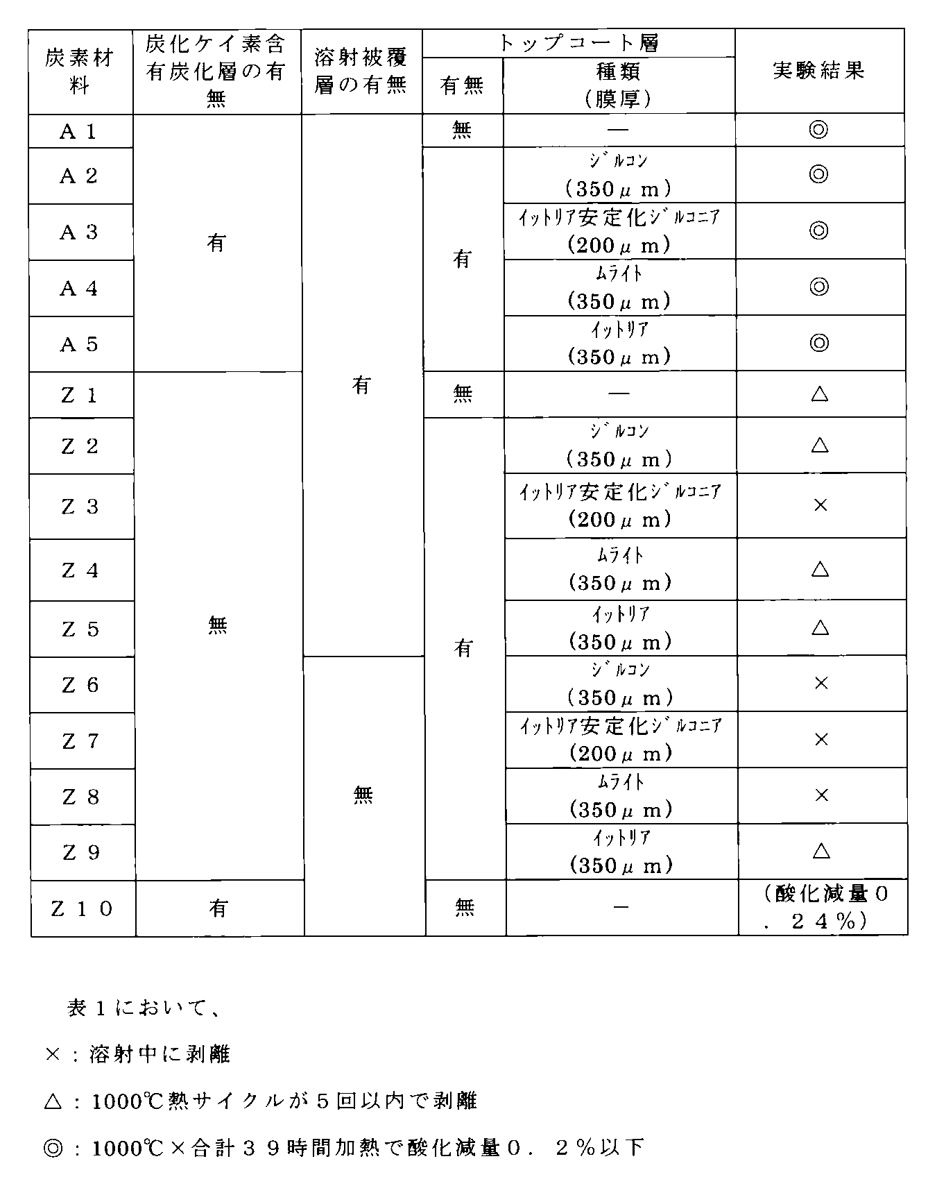
表1から明らかなように、実施例の炭素材料A1~A5は、比較例の炭素材料Z1~Z9に比べて、密着性と耐酸化消耗性とに優れていることが分かる。したがって、トップコート層の形成の有無に関わらず、炭素質基材の表面に炭化ケイ素含有炭化層を形成することが必要であることが理解できる。
(実験2)
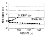
炭素材料A2及び炭素材料Z10を、空気中で1000℃に加熱して、重量変化による酸化消耗率の推移を調べたので、その結果を図3に示す。
炭素材料A2及び炭素材料Z10を、空気中で1000℃に加熱して、重量変化による酸化消耗率の推移を調べたので、その結果を図3に示す。
図3から明らかなように、炭素材料Z10では酸化消耗率が高く、質量が大きく減少しているのに対して、炭素材料A2では質量減少は見られず、質量が若干増大していることが認められた。尚、炭素材料A2における若干の増量は、トップコート層の酸化によるものであって、炭素材料の酸化は殆ど生じていないと推定される。
(実験3)
炭素材料A2を1000℃100時間加熱後、即時水中に投入して冷却し、冷却後、空気中1000℃で200時間の耐酸化試験を行ったので、当該試験後の断面写真を図4に、当該試験後の元素分析結果を表2に示す。
炭素材料A2を1000℃100時間加熱後、即時水中に投入して冷却し、冷却後、空気中1000℃で200時間の耐酸化試験を行ったので、当該試験後の断面写真を図4に、当該試験後の元素分析結果を表2に示す。
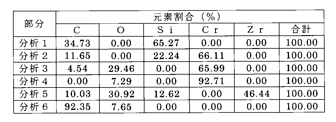
図4及び表2から明らかなように、炭素質基材上に形成された炭化ケイ素含有層上に、Crシリサイド層が形成されている(分析2部分)が、極めて過酷な試験のため、Crシリサイド層と溶射被覆層(分析4部分)とは剥離が生じている。しかしながら、Crシリサイド層と炭化ケイ素含有層(分析1部分)とは強固に密着した状態となっている。他に、金属クロム層では、耐酸化性試験のため一部に酸化が生じている(分析3部分)が、炭化ケイ素含有層には酸化消耗が生じておらず、酸素も検出されていない(分析1部分)。このCrシリサイド層と炭化ケイ素含有層との密着性により、優れた耐酸化消耗性と密着性とが発現されることが推測される。
〔第2実施例〕
(実施例1~7)
溶射被覆層の種類を、それぞれ、80重量%Cr−20重量%Ni、50重量%Cr−50重量%Ni、20重量%Cr−80重量%Ni、Cr3C2−25重量%NiCr、47重量%Co−29重量%Mo−18重量%Cr、38重量%Co−32重量%Ni−21重量%Cr−8重量%Al−0.5重量%Y、95重量%Ni−5重量%Alの比率としたこと以外は、それぞれ、上記第1実施例の実施例2と同様にして炭素材料を作製した。尚、溶射被覆層の厚みは、約50μmであった。
このようにして作製した炭素材料を、以下それぞれ、炭素材料B1~B7と称する。
(実施例1~7)
溶射被覆層の種類を、それぞれ、80重量%Cr−20重量%Ni、50重量%Cr−50重量%Ni、20重量%Cr−80重量%Ni、Cr3C2−25重量%NiCr、47重量%Co−29重量%Mo−18重量%Cr、38重量%Co−32重量%Ni−21重量%Cr−8重量%Al−0.5重量%Y、95重量%Ni−5重量%Alの比率としたこと以外は、それぞれ、上記第1実施例の実施例2と同様にして炭素材料を作製した。尚、溶射被覆層の厚みは、約50μmであった。
このようにして作製した炭素材料を、以下それぞれ、炭素材料B1~B7と称する。
(比較例)
溶射被覆層を形成しなかった(炭化ケイ素含有炭化層の表面に直接、トップコート層を形成した)こと以外は、上記第1実施例の実施例2と同様にして炭素材料を作製した。
このようにして作製した炭素材料を、以下、炭素材料Yと称する。
溶射被覆層を形成しなかった(炭化ケイ素含有炭化層の表面に直接、トップコート層を形成した)こと以外は、上記第1実施例の実施例2と同様にして炭素材料を作製した。
このようにして作製した炭素材料を、以下、炭素材料Yと称する。
(実験)
上記第1実施例の実験と同様にして、炭素材料B1~B7及び炭素材料Yの1000℃熱サイクルを5回行い、溶射被覆層又はトップコート層の剥離状態を観察した。酸化減量は、1000℃で39時間暴露後の重量変化を測定した。その結果を表3に示す。
上記第1実施例の実験と同様にして、炭素材料B1~B7及び炭素材料Yの1000℃熱サイクルを5回行い、溶射被覆層又はトップコート層の剥離状態を観察した。酸化減量は、1000℃で39時間暴露後の重量変化を測定した。その結果を表3に示す。
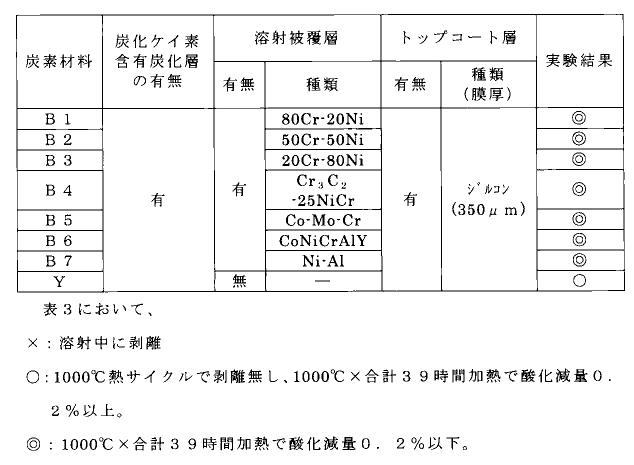
表3から明らかなように、実施例の炭素材料B1~B7は、比較例の炭素材料Yに比べて、密着性と耐酸化消耗性とに優れていることが分かる。したがって、シリサイドを形成する材料(炭素材料B1~B7に用いた80重量%Cr−20重量%Ni等)を用いて溶射被覆層を形成することで、金属クロム以外でも良好な密着性及び耐酸化消耗性が得られることが理解できる。
〔第3実施例〕
(実施例1)
嵩密度が1.91、平均細孔半径が0.6μmの等方性黒鉛材料(東洋炭素(株)製グレード名「HPG−59」)を35×35×20mmに加工し、炭素質基材とした。次に、ポリアミドイミド樹脂〔「AI−10」、小原化工(株)製〕をN−メチル−2ピロリドンに溶解して、20%溶液とした。この溶液にケイ素粉末〔和光純薬工業(株)製:粒度30~50μm〕を混合してスラリーを調製した。この際、ポリアミドイミド樹脂100重量部に対して、ケイ素粉末が60重量部となるように、ケイ素粉末の量を規定した。次いで、上記スラリーを上記炭素質基材の35×35mmの面に厚さが約1.5mm、塗布量が約4.0gとなるように塗布した後、乾燥機中において300℃で硬化させた。更に、真空炉にて1600℃まで昇温して30分保持した後、冷却し取り出して、炭素質基材の表面に炭化ケイ素含有炭化層を形成した。尚、この炭化ケイ素含有炭化層において、算術表面粗さRaは10μm、ビッカース硬さHVは1905、浸透部における浸透深さは0.5mm以上であった。
(実施例1)
嵩密度が1.91、平均細孔半径が0.6μmの等方性黒鉛材料(東洋炭素(株)製グレード名「HPG−59」)を35×35×20mmに加工し、炭素質基材とした。次に、ポリアミドイミド樹脂〔「AI−10」、小原化工(株)製〕をN−メチル−2ピロリドンに溶解して、20%溶液とした。この溶液にケイ素粉末〔和光純薬工業(株)製:粒度30~50μm〕を混合してスラリーを調製した。この際、ポリアミドイミド樹脂100重量部に対して、ケイ素粉末が60重量部となるように、ケイ素粉末の量を規定した。次いで、上記スラリーを上記炭素質基材の35×35mmの面に厚さが約1.5mm、塗布量が約4.0gとなるように塗布した後、乾燥機中において300℃で硬化させた。更に、真空炉にて1600℃まで昇温して30分保持した後、冷却し取り出して、炭素質基材の表面に炭化ケイ素含有炭化層を形成した。尚、この炭化ケイ素含有炭化層において、算術表面粗さRaは10μm、ビッカース硬さHVは1905、浸透部における浸透深さは0.5mm以上であった。
次に、上記炭化ケイ素含有炭化層の表面に、大気プラズマ溶射法により、金属クロムを溶射して溶射被覆層を形成することにより、炭素材料を作製した。金属クロムの溶射条件は、プラズマガスが流量63L/minのアルゴンガスと水素ガスの混合ガス、電源出力が38kW、材料粒度が5~45μmとした。ここで、上記金属クロムからなる溶射被覆層の厚みを測定したところ、約50μmであった。
更に上記溶射被覆層の表面に、プラズマガスが流量53L/minのアルゴンガスと水素ガスの混合ガス、電源出力が40kW、材料粒度が10~45μmとして、ジルコンを溶射してトップコート層を形成した。このトップコート層の厚みを測定したところ、約250μmであった。
このようにして作製した炭素材料を、炭素材料C1と称する。
このようにして作製した炭素材料を、炭素材料C1と称する。
(実施例2)
スラリーの塗布を、厚さが約0.2mm、塗布量が約0.5gとなるようにして、炭化ケイ素含有炭化層の算術表面粗さRaを10μm、ビッカース硬さHVを1850とした以外は、上記第3実施例の実施例1と同様にして炭素材料を得た。
このようにして作製した炭素材料を、炭素材料C2と称する。
スラリーの塗布を、厚さが約0.2mm、塗布量が約0.5gとなるようにして、炭化ケイ素含有炭化層の算術表面粗さRaを10μm、ビッカース硬さHVを1850とした以外は、上記第3実施例の実施例1と同様にして炭素材料を得た。
このようにして作製した炭素材料を、炭素材料C2と称する。
(実施例3)
スラリーの塗布を、厚さが約3.5mm、塗布量が約8.0gとなるようにして、炭化ケイ素含有炭化層の算術表面粗さRaを10μm、ビッカース硬さHVを2125とした以外は、上記第3実施例の実施例1と同様にして炭素材料を得た。
このようにして作製した炭素材料を、炭素材料C3と称する。
スラリーの塗布を、厚さが約3.5mm、塗布量が約8.0gとなるようにして、炭化ケイ素含有炭化層の算術表面粗さRaを10μm、ビッカース硬さHVを2125とした以外は、上記第3実施例の実施例1と同様にして炭素材料を得た。
このようにして作製した炭素材料を、炭素材料C3と称する。
(実験1)
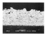
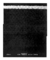
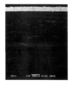
上記炭素材料C1~C3について、炭素材料C1については断面の目視により、炭素材料C2及びC3について、図5及び図6に示す断面SEM写真により、炭化ケイ素含有炭化層の浸透深さを確認した。図5は炭素材料C2、図6は炭素材料C3の断面SEM写真である。
上記炭素材料C1~C3について、炭素材料C1については断面の目視により、炭素材料C2及びC3について、図5及び図6に示す断面SEM写真により、炭化ケイ素含有炭化層の浸透深さを確認した。図5は炭素材料C2、図6は炭素材料C3の断面SEM写真である。
図5、図6について、上方の白い層から、トップコート層、溶射被覆層であり、溶射被覆層の下の灰色の部分が炭化ケイ素含有炭化層である。炭化ケイ素含有炭化層の下方の黒い部分が炭素質基材である。炭化ケイ素含有炭化層は、炭素質基材の表面に灰色に層状部分が形成されると共に、炭素質基材の気孔中にも灰色の部分が浸透しているのが確認できる。
ここで、炭化ケイ素含有炭化層の一部は、炭素質基材の表面から内部に浸透して形成されて、炭素質基材中に存在する開気孔中に浸入するが、図5、図6の断面写真では、灰色の部分(炭化ケイ素部分)が閉気孔の様に見える。しかしながら、実際には、炭素質基材中に孤立しているように見える灰色の部分(炭化ケイ素部分)は、表面の炭化ケイ素含有炭化層とつながっている。尚、このように見えるのは、炭素質基材の気孔は屈曲した形状(不定形状)であるのに対して、写真では一平面しか表せないことに起因している。
各々の炭化ケイ素含有炭化層の浸透部における浸透深さを読み取ると、図5から炭素材料C2は90μm以上、図6から炭素材料C3は3mm以上であった。また断面の目視から、炭素材料C1は1.8mm以上であった。
各々の炭化ケイ素含有炭化層の浸透部における浸透深さを読み取ると、図5から炭素材料C2は90μm以上、図6から炭素材料C3は3mm以上であった。また断面の目視から、炭素材料C1は1.8mm以上であった。
また炭素材料C1~C3について、溶射被覆層及びトップコート層の密着性を確認するため、室温から500℃に加熱して放冷するサイクルを2回繰り返す試験と、室温から1000℃に加熱して放冷するサイクルを2回繰り返す試験とを行った。その結果を表4に示す。
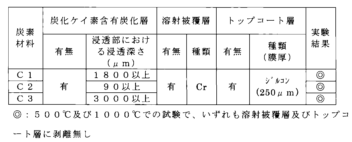
表4の試験結果から、炭化ケイ素含有炭化層における浸透部の浸透深さが50μm以上であれば、溶射被覆層及びトップコート層について良好な密着性が得られることが明らかである。
〔第4実施例〕
(実施例1)
炭素質基材として、平板状のC/Cコンポジット材(東洋炭素(株)製グレード名「CX−761」)を35×35×20mmに加工したものを用いた。次に、ポリアミドイミド樹脂〔「AI−10」、小原化工(株)製〕をN−メチル−2ピロリドンに溶解して、20%溶液とした。この溶液にケイ素粉末〔和光純薬工業(株)製:粒度30~50μm〕を混合してスラリーを調製した。この際、ポリアミドイミド樹脂100重量部に対して、ケイ素粉末が60重量部となるように、ケイ素粉末の量を規定した。次いで、上記スラリーを上記炭素質基材の35×35の面に、厚さが約1.5mm、塗布量が約4.0gとなるように塗布した後、乾燥機中において300℃で硬化させた。更に、真空炉にて1600℃まで昇温して30分保持した後、冷却し取り出して、炭素質基材の表面に炭化ケイ素含有炭化層を形成した。尚、この炭化ケイ素含有炭化層において、算術表面粗さRaは10μm、ビッカース硬さHVは2395、浸透部の浸透深さは約7mm以上であった。
(実施例1)
炭素質基材として、平板状のC/Cコンポジット材(東洋炭素(株)製グレード名「CX−761」)を35×35×20mmに加工したものを用いた。次に、ポリアミドイミド樹脂〔「AI−10」、小原化工(株)製〕をN−メチル−2ピロリドンに溶解して、20%溶液とした。この溶液にケイ素粉末〔和光純薬工業(株)製:粒度30~50μm〕を混合してスラリーを調製した。この際、ポリアミドイミド樹脂100重量部に対して、ケイ素粉末が60重量部となるように、ケイ素粉末の量を規定した。次いで、上記スラリーを上記炭素質基材の35×35の面に、厚さが約1.5mm、塗布量が約4.0gとなるように塗布した後、乾燥機中において300℃で硬化させた。更に、真空炉にて1600℃まで昇温して30分保持した後、冷却し取り出して、炭素質基材の表面に炭化ケイ素含有炭化層を形成した。尚、この炭化ケイ素含有炭化層において、算術表面粗さRaは10μm、ビッカース硬さHVは2395、浸透部の浸透深さは約7mm以上であった。
次に、上記炭化ケイ素含有炭化層の表面に、大気プラズマ溶射法により、アルミナを溶射して溶射被覆層を形成することにより、炭素材料を作製した。アルミナの溶射条件は、プラズマガスが流量53L/minのアルゴンガスと水素ガスの混合ガス、電源出力が40kW、材料粒度が10~45μmとした。イットリア安定化ジルコニアの溶射条件は、プラズマガスが流量50L/minのアルゴンガスと水素ガスの混合ガス、電源出力を44kW、材料粒度は10~45μmとした。ここで、上記アルミナからなる溶射被覆層の厚みを測定したところ、約50μmであった。
尚、上記炭素材料の構造は、第一実施例で挙げた図2に示したものと同様に、炭素質基材1の表面に、炭化ケイ素含有炭化層2と、溶射被覆層3、トップコート層4とが順に形成されている構造となっている。
このようにして作製した炭素材料を、以下、炭素材料D1と称する。
このようにして作製した炭素材料を、以下、炭素材料D1と称する。
(実施例2)
スラリーの塗布を、厚さが約0.2mm、塗布量が約0.5gとなるようにして、炭化ケイ素含有炭化層の算術表面粗さRaを10μm、ビッカース硬さHVを1850とした以外は、第4実施例の実施例1と同様にして炭素材料を得た。
このようにして作製した炭素材料を、炭素材料D2と称する。
スラリーの塗布を、厚さが約0.2mm、塗布量が約0.5gとなるようにして、炭化ケイ素含有炭化層の算術表面粗さRaを10μm、ビッカース硬さHVを1850とした以外は、第4実施例の実施例1と同様にして炭素材料を得た。
このようにして作製した炭素材料を、炭素材料D2と称する。
(実施例3)
スラリーの塗布を、厚さが約3.5mm、塗布量が約8.0gとなるようにして、炭化ケイ素含有炭化層の算術表面粗さRaを10μm、ビッカース硬さHVを2125とした以外は、第4実施例の実施例1と同様にして炭素材料を得た。
このようにして作製した炭素材料を、炭素材料D3と称する。
スラリーの塗布を、厚さが約3.5mm、塗布量が約8.0gとなるようにして、炭化ケイ素含有炭化層の算術表面粗さRaを10μm、ビッカース硬さHVを2125とした以外は、第4実施例の実施例1と同様にして炭素材料を得た。
このようにして作製した炭素材料を、炭素材料D3と称する。
(比較例)
炭化ケイ素含有炭化層を形成せず、上記炭素質材料に直接同条件にてアルミナを溶射した以外は、第4実施例の実施例1と同様にして炭素材料を得た。
このようにして作製した炭素材料を、炭素材料Xと称する。
炭化ケイ素含有炭化層を形成せず、上記炭素質材料に直接同条件にてアルミナを溶射した以外は、第4実施例の実施例1と同様にして炭素材料を得た。
このようにして作製した炭素材料を、炭素材料Xと称する。
(実験1)
上記炭素材料D1~D3について、断面SEM写真により、炭化ケイ素含有炭化層の浸透深さを確認した。図7は炭素材料D1、図8は炭素材料D2、図9は炭素材料D3の断面SEM写真である。
上記炭素材料D1~D3について、断面SEM写真により、炭化ケイ素含有炭化層の浸透深さを確認した。図7は炭素材料D1、図8は炭素材料D2、図9は炭素材料D3の断面SEM写真である。
図7~図9について、上方の白い層から、トップコート層、溶射被覆層であり、溶射被覆層の下の灰色の部分が炭化ケイ素含有炭化層である。炭化ケイ素含有炭化層の下方の黒い部分が炭素質基材である。炭化ケイ素含有炭化層は、炭素質基材の表面に灰色に層状部分が形成されると共に、炭素質基材の気孔中にも灰色の部分が浸透しているのが確認できる。尚、図7~図9の断面写真では、灰色の部分(炭化ケイ素部分)が閉気孔の様に見えるが、前記第3実施例と同様に、灰色の部分は、表面の炭化ケイ素含有炭化層とつながっている。
各々の炭化ケイ素含有炭化層の浸透部の浸透深さを図7~図9から読み取ると、図7から炭素材料D1は約7mm以上、図8から炭素材料D2は約2mm以上、図9から炭素材料D3は約10mm以上(SEM写真には収まりきっていないため、実物の断面を目視で確認)である。
(実験2)
上記炭素材料D1~D3及び炭素材料Xを600℃まで加熱し、常温の水中に投下する熱衝撃試験を行った所、炭素材料Xは溶射被覆層が剥離した。これに対して、炭素材料D1~D3は溶射被覆層に剥離は見られず、極めて強固に密着していることが確認された。
上記炭素材料D1~D3及び炭素材料Xを600℃まで加熱し、常温の水中に投下する熱衝撃試験を行った所、炭素材料Xは溶射被覆層が剥離した。これに対して、炭素材料D1~D3は溶射被覆層に剥離は見られず、極めて強固に密着していることが確認された。
(実験3)
炭素材料D1のアルミナの溶射被覆層上に、SUS304のブロックを載置し、真空中(0.05~0.10Torr)で1300℃、3時間保持した。その結果、炭素材料D1とSUS304とは反応が生じておらず、溶射被覆層が有効に機能していることが裏付けられた。
炭素材料D1のアルミナの溶射被覆層上に、SUS304のブロックを載置し、真空中(0.05~0.10Torr)で1300℃、3時間保持した。その結果、炭素材料D1とSUS304とは反応が生じておらず、溶射被覆層が有効に機能していることが裏付けられた。
〔第5実施例〕
(実施例1)
嵩密度が1.91、平均細孔半径が0.6μmの等方性黒鉛材料(東洋炭素(株)製グレード名「HPG−59」)を50×50×5mmに加工し、炭素質基材とした。次に、ポリアミドイミド樹脂〔「AI−10」、小原化工(株)製〕をN−メチル−2ピロリドンに溶解して、20%溶液とした。この溶液にケイ素粉末〔和光純薬工業(株)製:粒度30~50μm〕を混合してスラリーを調製した。この際、ポリアミドイミド樹脂100重量部に対して、ケイ素粉末が60重量部となるように、ケイ素粉末の量を規定した。次いで、上記スラリーを上記炭素質基材の外面部分に厚さが約3mmとなるように塗布した後、乾燥機中において300℃で硬化させた。更に、真空炉にて1600℃まで昇温して30分保持した後、冷却し取り出して、炭素質基材の表面に炭化ケイ素含有炭化層を形成した。この炭化ケイ素含有炭化層表面を研磨して、算術表面粗さRaを3μmに調整した。またこの炭化ケイ素含有炭化層のビッカース硬さHVは2395、浸透部の浸透深さは0.5mm以上であった。
(実施例1)
嵩密度が1.91、平均細孔半径が0.6μmの等方性黒鉛材料(東洋炭素(株)製グレード名「HPG−59」)を50×50×5mmに加工し、炭素質基材とした。次に、ポリアミドイミド樹脂〔「AI−10」、小原化工(株)製〕をN−メチル−2ピロリドンに溶解して、20%溶液とした。この溶液にケイ素粉末〔和光純薬工業(株)製:粒度30~50μm〕を混合してスラリーを調製した。この際、ポリアミドイミド樹脂100重量部に対して、ケイ素粉末が60重量部となるように、ケイ素粉末の量を規定した。次いで、上記スラリーを上記炭素質基材の外面部分に厚さが約3mmとなるように塗布した後、乾燥機中において300℃で硬化させた。更に、真空炉にて1600℃まで昇温して30分保持した後、冷却し取り出して、炭素質基材の表面に炭化ケイ素含有炭化層を形成した。この炭化ケイ素含有炭化層表面を研磨して、算術表面粗さRaを3μmに調整した。またこの炭化ケイ素含有炭化層のビッカース硬さHVは2395、浸透部の浸透深さは0.5mm以上であった。
次に、上記炭化ケイ素含有炭化層の表面に、大気プラズマ溶射法により、金属クロムを溶射して溶射被覆層を形成することにより、炭素材料を作製した。金属クロムの溶射条件は、プラズマガスが流量63L/minのアルゴンガスと水素ガスの混合ガス、電源出力が38kW、材料粒度が5~45μmとした。ここで、上記金属クロムからなる溶射被覆層の厚みを測定したところ、約50μmであった。更に上記溶射被覆層の表面に、プラズマガスが流量53L/minのアルゴンガスと水素ガスの混合ガス、電源出力が40kW、材料粒度が10~45μmとして、ジルコンを溶射してトップコート層を形成した。このトップコート層の厚みを測定したところ、約250μmであった。
このようにして作製した炭素材料を、炭素材料E1と称する。
このようにして作製した炭素材料を、炭素材料E1と称する。
(実施例2)
炭化ケイ素含有炭化層表面の算術表面粗さRaを9μmに調整した以外は実施例1と同様にして、炭化ケイ素含有炭化層上に溶射被覆層及びトップコート層を形成した。このようにして作製した炭素材料を、炭素材料E2と称する。
炭化ケイ素含有炭化層表面の算術表面粗さRaを9μmに調整した以外は実施例1と同様にして、炭化ケイ素含有炭化層上に溶射被覆層及びトップコート層を形成した。このようにして作製した炭素材料を、炭素材料E2と称する。
(実施例3)
炭化ケイ素含有炭化層表面の算術表面粗さRaを25μmに調整した以外は実施例1と同様にして、炭化ケイ素含有炭化層上に溶射被覆層及びトップコート層を形成した。このようにして作製した炭素材料を、炭素材料E3と称する。
炭化ケイ素含有炭化層表面の算術表面粗さRaを25μmに調整した以外は実施例1と同様にして、炭化ケイ素含有炭化層上に溶射被覆層及びトップコート層を形成した。このようにして作製した炭素材料を、炭素材料E3と称する。
(実験)
炭素材料E1~E3について、溶射被覆層及びトップコート層の密着性を確認するため、室温から500℃に加熱して放冷するサイクルを2回繰り返す試験と、室温から1000℃に加熱して放冷するサイクルを2回繰り返す試験とを行った。その結果を表5に示す。
炭素材料E1~E3について、溶射被覆層及びトップコート層の密着性を確認するため、室温から500℃に加熱して放冷するサイクルを2回繰り返す試験と、室温から1000℃に加熱して放冷するサイクルを2回繰り返す試験とを行った。その結果を表5に示す。
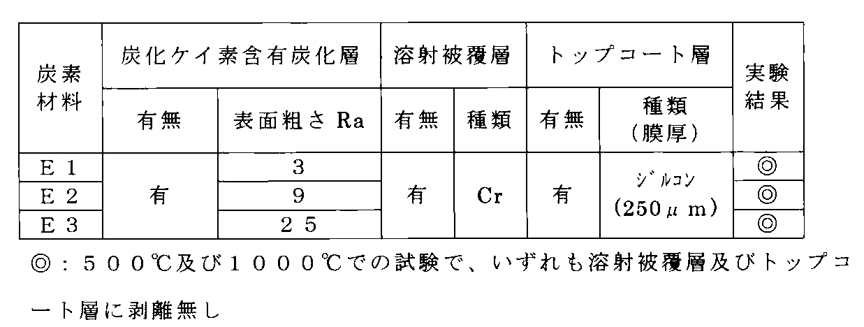
表5の試験結果から、表面粗さRaが3μm以上であれば、溶射被覆層及びトップコート層について良好な密着性が得られることが分かる。
本発明は、焼結炭素製の各種ロール類、金属及びガラス質溶解坩堝、各種電池及び電解用電極、飛翔体構造部材、発熱体などに好適に用いられる。
1:炭素質基材
2:炭化ケイ素含有炭化層
3:溶射被覆層
4:トップコート層
2:炭化ケイ素含有炭化層
3:溶射被覆層
4:トップコート層
Claims (8)
- 炭素質基材と、
該炭素質基材の表面に形成され、算術表面粗さRaが1μm以上、ビッカース硬さHVが50以上であって、少なくとも一部が上記炭素質基材中に浸透しており、浸透部における浸透深さが50μm以上である部分が存在する炭化ケイ素含有炭化層と、
該炭化ケイ素含有炭化層の表面に形成された溶射被覆層と、
を備えることを特徴とする溶射被覆層を有する炭素材料。 - 上記溶射被覆層は、上記炭化ケイ素含有炭化層とシリサイドを形成できる物質からなる、請求項1に記載の溶射被覆層を有する炭素材料。
- 上記シリサイドは溶射時に形成される、請求項2に記載の溶射被覆層を有する炭素材料。
- 上記溶射被覆層の表面には、溶射により形成されたトップコート層が設けられている、請求項1~3の何れか1項に記載の溶射被覆層を有する炭素材料。
- 上記炭化ケイ素含有炭化層には金属ケイ素が含まれている、請求項1~4のいずれか1項に記載の溶射被覆層を有する炭素材料。
- 酸化雰囲気中で熱せられた金属材が走行する熱処理炉用ハースロールにおいて、ロール胴部が請求項1~5の何れか1項に記載の溶射被覆層を有する炭素材料であることを特徴とするハースロール。
- 炭素質基材と、炭素質基材上に設けられた炭化ケイ素含有炭化層と、金属又は金属酸化物からなる被覆層とを備え、
前記炭化ケイ素含有炭化層と被覆層との間に、金属シリサイド層が形成されていることを特徴とする炭素材料。 - 炭素質基材に、金属ケイ素と樹脂分とを溶媒中に分散させた溶液を塗布する工程と、
前記溶液の溶媒を揮発させる工程と、
熱処理により、前記金属ケイ素と炭素質基材中の炭素及び前記樹脂分中の炭素とを反応させて、前記炭素質基材上に炭化ケイ素含有炭化層を生成させる工程と、
前記炭化ケイ素含有炭化層上に溶射により溶射被覆層を設ける工程と、
を含むことを特徴とする溶射被覆層を有する炭素材料の製造方法。
Priority Applications (3)
| Application Number | Priority Date | Filing Date | Title |
|---|---|---|---|
| CN201380036152.0A CN104487403B (zh) | 2012-07-06 | 2013-07-08 | 具有热喷涂被覆层的碳材料 |
| JP2014523824A JP6110852B2 (ja) | 2012-07-06 | 2013-07-08 | 溶射被覆層を有する炭素材料 |
| EP13813331.9A EP2871173B1 (en) | 2012-07-06 | 2013-07-08 | Carbon material having thermal sprayed coating layer |
Applications Claiming Priority (2)
| Application Number | Priority Date | Filing Date | Title |
|---|---|---|---|
| JP2012152980 | 2012-07-06 | ||
| JP2012-152980 | 2012-07-06 |
Publications (1)
| Publication Number | Publication Date |
|---|---|
| WO2014007406A1 true WO2014007406A1 (ja) | 2014-01-09 |
Family
ID=49882154
Family Applications (1)
| Application Number | Title | Priority Date | Filing Date |
|---|---|---|---|
| PCT/JP2013/069079 Ceased WO2014007406A1 (ja) | 2012-07-06 | 2013-07-08 | 溶射被覆層を有する炭素材料 |
Country Status (5)
| Country | Link |
|---|---|
| EP (1) | EP2871173B1 (ja) |
| JP (1) | JP6110852B2 (ja) |
| CN (1) | CN104487403B (ja) |
| TW (1) | TW201418190A (ja) |
| WO (1) | WO2014007406A1 (ja) |
Families Citing this family (7)
| Publication number | Priority date | Publication date | Assignee | Title |
|---|---|---|---|---|
| CN107058853A (zh) * | 2017-03-17 | 2017-08-18 | 广西浩昌敏再生资源利用有限公司 | 一种镀锌合金钢材的制备方法 |
| CN106987758A (zh) * | 2017-03-17 | 2017-07-28 | 广西浩昌敏再生资源利用有限公司 | 一种镀膜合金钢材的制备方法 |
| KR102084841B1 (ko) * | 2018-03-22 | 2020-03-09 | 주식회사 티엠비 | 탄소 소재의 표면조도 제어를 위한 표면처리방법 |
| CN112745146B (zh) * | 2021-01-11 | 2022-07-12 | 上海大学 | 一种碳/碳复合材料涂层的局部缺陷晶须或片状增强修补方法及修补涂层 |
| KR102923768B1 (ko) * | 2021-12-16 | 2026-02-04 | 닛폰 피스톤 린구 가부시키가이샤 | 용사 피막, 슬라이딩 부재 및 피스톤 링 |
| US12595216B2 (en) | 2023-04-18 | 2026-04-07 | Honeywell International Inc. | Metal carbide infiltrated C/C composites |
| CN117800766B (zh) * | 2023-12-29 | 2025-12-19 | 浙江柔震科技有限公司 | 石墨蒸发舟及其制备方法 |
Citations (5)
| Publication number | Priority date | Publication date | Assignee | Title |
|---|---|---|---|---|
| JPH0570268A (ja) | 1991-09-17 | 1993-03-23 | Tocalo Co Ltd | 密着性に優れた金属溶射被覆層を有する炭素部材 |
| JPH0812474A (ja) | 1992-08-25 | 1996-01-16 | Toyo Tanso Kk | 炭素−SiC複合材料の製造方法 |
| JPH08218115A (ja) * | 1995-02-10 | 1996-08-27 | Nippon Steel Corp | 高強度、高耐摩耗性、かつならい性に優れたカーボンロール及びその製造方法 |
| JPH09287614A (ja) * | 1996-04-22 | 1997-11-04 | Nippon Steel Corp | 高強度、高耐摩耗性、かつならい性に優れたロール |
| JP2000045037A (ja) * | 1998-05-27 | 2000-02-15 | Toyo Tanso Kk | 熱処理炉用ハースロール |
Family Cites Families (10)
| Publication number | Priority date | Publication date | Assignee | Title |
|---|---|---|---|---|
| JP3129383B2 (ja) * | 1994-02-16 | 2001-01-29 | 三菱重工業株式会社 | 酸化物被覆炭化珪素材とその製法 |
| US5560993A (en) * | 1994-02-16 | 1996-10-01 | Mitsubishi Jukogyo Kabushiki Kaisha | Oxide-coated silicon carbide material and method of manufacturing same |
| JP4277973B2 (ja) * | 2001-07-19 | 2009-06-10 | 日本碍子株式会社 | イットリア−アルミナ複合酸化物膜の製造方法、イットリア−アルミナ複合酸化物膜および耐蝕性部材 |
| US7507481B2 (en) * | 2002-11-20 | 2009-03-24 | Shin-Etsu Chemical Co., Ltd. | Heat resistant coated member, making method, and treatment using the same |
| US7354651B2 (en) * | 2005-06-13 | 2008-04-08 | General Electric Company | Bond coat for corrosion resistant EBC for silicon-containing substrate and processes for preparing same |
| CN100404464C (zh) * | 2005-07-28 | 2008-07-23 | 西北工业大学 | 碳/碳复合材料基二硅化钽/碳化硅涂层及其制备方法 |
| JP5070910B2 (ja) * | 2007-03-30 | 2012-11-14 | 株式会社Ihi | セラミックス基複合部材およびセラミックス基複合部材の製造方法 |
| JP5129500B2 (ja) * | 2007-04-13 | 2013-01-30 | 三菱重工業株式会社 | 耐熱材料ならびにその製造方法および修復方法 |
| CN100497265C (zh) * | 2007-08-16 | 2009-06-10 | 中南大学 | 一种C/SiC复合材料表面抗氧化涂层及其制备方法 |
| CN101863683B (zh) * | 2009-04-15 | 2013-10-02 | 中国科学院上海硅酸盐研究所 | 抗氧化性涂层及其制备方法 |
-
2013
- 2013-07-05 TW TW102124178A patent/TW201418190A/zh unknown
- 2013-07-08 WO PCT/JP2013/069079 patent/WO2014007406A1/ja not_active Ceased
- 2013-07-08 EP EP13813331.9A patent/EP2871173B1/en active Active
- 2013-07-08 JP JP2014523824A patent/JP6110852B2/ja active Active
- 2013-07-08 CN CN201380036152.0A patent/CN104487403B/zh active Active
Patent Citations (5)
| Publication number | Priority date | Publication date | Assignee | Title |
|---|---|---|---|---|
| JPH0570268A (ja) | 1991-09-17 | 1993-03-23 | Tocalo Co Ltd | 密着性に優れた金属溶射被覆層を有する炭素部材 |
| JPH0812474A (ja) | 1992-08-25 | 1996-01-16 | Toyo Tanso Kk | 炭素−SiC複合材料の製造方法 |
| JPH08218115A (ja) * | 1995-02-10 | 1996-08-27 | Nippon Steel Corp | 高強度、高耐摩耗性、かつならい性に優れたカーボンロール及びその製造方法 |
| JPH09287614A (ja) * | 1996-04-22 | 1997-11-04 | Nippon Steel Corp | 高強度、高耐摩耗性、かつならい性に優れたロール |
| JP2000045037A (ja) * | 1998-05-27 | 2000-02-15 | Toyo Tanso Kk | 熱処理炉用ハースロール |
Also Published As
| Publication number | Publication date |
|---|---|
| JP6110852B2 (ja) | 2017-04-05 |
| TW201418190A (zh) | 2014-05-16 |
| EP2871173B1 (en) | 2019-09-04 |
| CN104487403B (zh) | 2017-08-18 |
| JPWO2014007406A1 (ja) | 2016-06-02 |
| CN104487403A (zh) | 2015-04-01 |
| EP2871173A1 (en) | 2015-05-13 |
| EP2871173A4 (en) | 2016-03-23 |
Similar Documents
| Publication | Publication Date | Title |
|---|---|---|
| JP6110852B2 (ja) | 溶射被覆層を有する炭素材料 | |
| US9145339B2 (en) | Material having a multilayer architecture and intended for being contacted with liquid silicon | |
| Pourasad et al. | In-situ synthesis of SiC-ZrB2 coating by a novel pack cementation technique to protect graphite against oxidation | |
| Xu et al. | Ultra-high temperature oxidation behavior of micro-laminated ZrC/MoSi2 coating on C/C composite | |
| Qian-Gang et al. | Microstructure and anti-oxidation property of CrSi2–SiC coating for carbon/carbon composites | |
| JP3927574B2 (ja) | NiCoCrAl薄膜 | |
| US8980434B2 (en) | Mo—Si—B—based coatings for ceramic base substrates | |
| Chen et al. | Microstructure and oxidation behavior of a novel bilayer (c-AlPO4–SiCw–mullite)/SiC coating for carbon fiber reinforced CMCs | |
| Li et al. | Dynamic oxidation resistance and residual mechanical strength of ZrB2-CrSi2-SiC-Si/SiC coated C/C composites | |
| JP2017002386A (ja) | 溶融金属処理機器およびその製造方法ならびに保護皮膜およびその製造方法 | |
| JP2019507828A (ja) | 基材上に高温保護層を接合するための付着促進層、並びにそれの製造方法 | |
| WO1998043928A1 (fr) | Materiau composite de carbone/de carbure de silicium | |
| Tao et al. | Microstructure and anti-oxidation properties of multi-composition ceramic coatings for carbon/carbon composites | |
| Celebi Efe et al. | Pack siliconizing of Ti6Al4V alloy | |
| JP3081765B2 (ja) | 炭素部材およびその製造方法 | |
| JP4690709B2 (ja) | 耐熱材料およびその製造方法 | |
| CN107460476A (zh) | 一种钛合金表面TiC增强钛基复合涂层及其制备方法 | |
| JP2002371383A (ja) | 耐熱性被覆部材 | |
| WO2013097205A1 (zh) | 金属多孔材料的孔径调节方法及金属多孔材料的孔结构 | |
| JP2018004105A (ja) | 溶融金属処理機器およびその製造方法 | |
| CN112299882A (zh) | 一种碳材料表面HfC基三元碳化物梯度涂层的原位制备方法 | |
| JPH08143385A (ja) | 複合皮膜を有する炭素部材とその製造方法 | |
| CN109437974B (zh) | 一种具有Mo-Si-B-O高温抗氧化涂层的C/SiC复合材料及其制备方法 | |
| CN103160708B (zh) | 一种NiAl-2.5Ta-7.5Cr-20Co合金作为高温自润滑材料的应用 | |
| KR102845759B1 (ko) | 열방호 소재용 금속 탄화물 계면층 제조방법 및 이를 이용한 열방호 소재 |
Legal Events
| Date | Code | Title | Description |
|---|---|---|---|
| 121 | Ep: the epo has been informed by wipo that ep was designated in this application |
Ref document number: 13813331 Country of ref document: EP Kind code of ref document: A1 |
|
| DPE1 | Request for preliminary examination filed after expiration of 19th month from priority date (pct application filed from 20040101) | ||
| ENP | Entry into the national phase |
Ref document number: 2014523824 Country of ref document: JP Kind code of ref document: A |
|
| NENP | Non-entry into the national phase |
Ref country code: DE |
|
| WWE | Wipo information: entry into national phase |
Ref document number: 2013813331 Country of ref document: EP |