WO2014009987A1 - Étui pour lentille de contact - Google Patents
Étui pour lentille de contact Download PDFInfo
- Publication number
- WO2014009987A1 WO2014009987A1 PCT/JP2012/004421 JP2012004421W WO2014009987A1 WO 2014009987 A1 WO2014009987 A1 WO 2014009987A1 JP 2012004421 W JP2012004421 W JP 2012004421W WO 2014009987 A1 WO2014009987 A1 WO 2014009987A1
- Authority
- WO
- WIPO (PCT)
- Prior art keywords
- lens
- contact lens
- housing recess
- lid
- holding body
- Prior art date
- Legal status (The legal status is an assumption and is not a legal conclusion. Google has not performed a legal analysis and makes no representation as to the accuracy of the status listed.)
- Ceased
Links
Images










Classifications
-
- A—HUMAN NECESSITIES
- A45—HAND OR TRAVELLING ARTICLES
- A45C—PURSES; LUGGAGE; HAND CARRIED BAGS
- A45C11/00—Receptacles for purposes not provided for in groups A45C1/00-A45C9/00
- A45C11/005—Contact lens cases
-
- A—HUMAN NECESSITIES
- A45—HAND OR TRAVELLING ARTICLES
- A45C—PURSES; LUGGAGE; HAND CARRIED BAGS
- A45C13/00—Details; Accessories
- A45C13/02—Interior fittings; Means, e.g. inserts, for holding and packing articles
-
- G—PHYSICS
- G02—OPTICS
- G02C—SPECTACLES; SUNGLASSES OR GOGGLES INSOFAR AS THEY HAVE THE SAME FEATURES AS SPECTACLES; CONTACT LENSES
- G02C11/00—Non-optical adjuncts; Attachment thereof
Definitions
- the present invention is used when a contact lens, in particular, a regular or periodic exchange type water-containing soft contact lens is immersed in a storage solution for storage, or is used when a contact lens is sterilized using hydrogen peroxide solution.
- the present invention relates to a contact lens case.
- a contact lens case has been widely used as a structure that can easily store and store such a storage solution or a liquid agent such as hydrogen peroxide solution and a contact lens.
- a container body including a storage recess for storing a storage liquid and a contact lens, and an upper opening of the storage recess are mounted. And a lid that covers the upper opening.
- JP 2002-526203 A discloses platinum on the bottom surface of the shallow lens housing recess and the inner surface of the peripheral wall. Cases with a layered structure have been proposed.
- hydrogen peroxide water is harmless as water and oxygen after decomposition, but if left undecomposed, it becomes an irritant to the eye. This is because the hydrogen peroxide is completely decomposed and neutralized before the end of the contact lens sterilization treatment by accelerating and adjusting the decomposition reaction.
- the storage recess of the contact lens case is filled with a liquid such as a preservative solution or hydrogen peroxide solution, and then the user picks it with a finger and removes it from the eye.
- the contact lens may be stored in the receiving recess.
- the solution filled in the receiving recess is hydrogen peroxide
- the hydrogen peroxide solution before neutralization which is an irritant
- the other contact lens is removed from the eye with the fingers, there is a risk that the hydrogen peroxide solution will adhere to the eyes.
- the present invention has been made in the background of the above-mentioned circumstances, and a solution to that problem is that the contact lens can be easily and stably stored and taken out from the receiving recess, and the contact lens
- An object of the present invention is to provide a contact lens case having a novel structure capable of improving hygiene and safety during storage / removal.
- a container body having a housing recess for housing a contact lens and a liquid agent for immersing the contact lens, and the container body connected to the container body through a hinge portion so as to be freely opened and closed.
- a contact lens case including a lid that covers the upper opening of the recess, wherein the housing recess holds a lens holder that holds the contact lens in a displaceable manner, and the lid And the lens holder are connected via a connecting member, and the lens holder is moved up and down in accordance with the opening and closing operation around the hinge portion of the lid, Displacement restricting means for restricting the vertical displacement in the vertical direction that is the depth direction of the housing recess is provided.
- the lens holding body is displaced up and down in accordance with the opening and closing operation of the lid, and the up and down displacement of the holding body is caused by the displacement regulating means in the vertical direction of the housing recess. Is regulated. Accordingly, when the contact lens case is rotated in the opening direction, the rotation of the lid is transmitted to the lens holder via the connecting member, thereby being displaced obliquely upward with respect to the lens holder. External force to be applied will be added. At this time, since the upward displacement of the lens holding body is regulated in the vertical direction of the housing recess by the regulating means, the lens holding body can be pulled straight up above the housing recess.
- the lens holder is moved above the accommodation recess as the lid is moved in the opening direction.
- the lens removed from the eye by the user can be easily placed on the lens holder that is pulled upward from the bottom side of the lens housing recess, and is also used when placing the lens. It is possible to avoid the person's fingers from coming into contact with the liquid agent accommodated in the accommodation recess. Therefore, unlike the conventional case, it is possible to avoid the danger that the user's fingers come into contact with the preservation solution and the preservation solution is contaminated, or the hydrogen peroxide solution contacts the fingers and eyes.
- the displacement restraining means regulates the up-and-down displacement of the lens holder accompanying the opening / closing operation of the lid in the vertical direction of the housing recess.
- the lens can be prevented from being displaced due to the lens holder being slid laterally in the liquid, and the contact lens is displaced in the vertical direction in a state where the lens is stably held by the lens holder. It can be done. Therefore, it is not necessary to provide a protective wall with a large protruding height around the contact lens holding area to prevent the lens from falling off the lens holding body, and access to the contact lens held by the lens holding body is possible. Becomes easy.
- the connecting member may be any member as long as it can connect both of them to transmit the rotation of the lid to the lens holder, and any structure such as a half-broken link mechanism or elastic bending piece can be adopted. It is. Furthermore, the displacement restricting means may be any as long as it can restrict the movement of the lens holder in the accommodating recess in the vertical direction that is the depth direction of the accommodating recess.
- a guide groove that extends in the vertical direction and a protrusion that slides in the guide groove may be provided between the opposing surfaces of the housing recess and the lens holding body to restrict the displacement direction of the lens holding body,
- a protrusion protruding upward from the bottom surface may be provided, and the protrusion may be disposed through a through hole formed in the lens holder so that the displacement of the lens holder is guided in the protruding direction of the protrusion.
- the lens holding body displaced to an upper position of the housing recess by opening the lid is temporarily placed at the upper position.
- Temporary holding means for holding is provided.
- the lens holding body positioned above the housing recess can be temporarily held at the upper position by the opening operation of the lid. Therefore, even if the hand is released from the lid, the lens holder can be held at the upper position, and the contact lens can be easily attached to and detached from the lens holder.
- the temporary holding means employs any temporary holding mechanism such as engaging the lens holder with the elastically deformable overpass projection or sliding the lens holder laterally to engage the engaging portion. Is possible.
- the displacement restricting means includes a guide groove extending in the vertical direction and formed in an inner surface of the housing recess, and the lens. And a sliding protrusion that is projected from the holding body and is slid into the guide groove.
- the displacement restricting means can be provided between the housing recess and the facing surface of the lens holding body, and the displacement of the lens holding body can be restricted without increasing the size of the case.
- an upper end portion of the guide groove is bent toward the hinge portion side of the lid body, thereby extending in a lateral direction.
- the temporary holding means configured to temporarily hold the lens holding body at an upper position of the receiving recess is configured by being connected to the side groove, and the sliding protrusion is fitted into the side groove.
- the temporary holding means can be configured with a simple structure in which the upper end portion of the guide groove extends toward the hinge portion to form the side groove. Moreover, since the lens holding body is moved to the hinge part side of the lid body by fitting the sliding protrusion of the lens holding body into the side groove, the front side of the housing recess (the side opposite to the hinge part side) ) Can secure a wide space. Thereby, operations such as injection of the liquid agent into the housing recess are facilitated. Further, since the lid is further opened in order to move the lens holder from the upper end portion of the guide groove to the side groove, the attaching / detaching operation of the contact lens to the lens holder is not obstructed by the lid. It can be done easily.
- the liquid agent accommodated in the accommodation recess is an aqueous solution of hydrogen peroxide, and the lens holding A catalyst is held against the body.
- the contact lens is immersed in an aqueous solution of hydrogen peroxide and sterilized. That is, when the contact lens is attached to and detached from the lens holder, the lens holder is pulled up above the housing recess, so that the hydrogen peroxide before neutralization, which is an irritant, is absorbed by the user's fingers and eyes. It is possible to reliably prevent the danger of touching the surface. Furthermore, since the catalyst is held by the lens holder, it is possible to prevent neutralization of the hydrogen peroxide filled in the housing recess before the lens is immersed, so that a more efficient process is possible.
- the contact lens can be sterilized with hydrogen oxide.
- a pair of lens placement portions are formed on the lens holder. According to this aspect, it is possible to raise and lower the lens mounting portion for both eyes by opening and closing one lid, and it is possible to improve operability. Further, since the lens mounting portions for both eyes can be housed in one housing recess, the entire case can be made compact and the number of parts can be reduced.
- the pair of lens placement portions has a partial spherical shell shape that is convex upward.
- the back side of the contact lens removed from the eye is stored in contact with the lens mounting portion, while when attached to the eye, only the front side of the contact lens is picked with fingers, and the lens holder Can be taken out from. Therefore, when wearing a contact lens, it can be advantageously avoided that the back side of the contact lens that comes into direct contact with the eyes comes into contact with the fingers and is contaminated, or foreign matter adheres to it. It is possible to improve the surface and the feeling of wearing.
- the lens holding body is displaced up and down in accordance with the opening / closing operation of the lid, and the up / down displacement of the lens holding body is regulated in the vertical direction of the housing recess by the displacement regulating means. Accordingly, as the lid is moved in the opening direction, the lens holder is moved above the receiving recess, so that the lens removed from the eye by the user can be easily placed on the lens holder. In addition, it is possible to avoid the user's fingers from coming into contact with the liquid agent accommodated in the accommodation recess when the lens is placed, and it is possible to improve hygiene and safety.
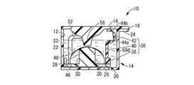
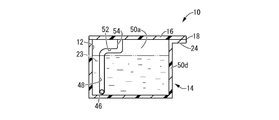
- the side view of the case for contact lenses which is the 1st Embodiment of this invention The top view of the case for contact lenses shown in FIG. III-III sectional view in FIG. IV-IV sectional drawing in FIG.
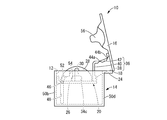
- the top view of the lens holding body which comprises the case for contact lenses shown in FIG. The side view which shows the use condition of the case for contact lenses shown in FIG.
- the side view which shows another use condition of the case for contact lenses shown in FIG. The side view which shows another use condition of the case for contact lenses shown in FIG.
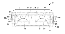
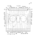
- the side view of the case for contact lenses shown in FIG. The top view of the case for contact lenses shown in FIG. XII-XII sectional drawing in FIG.
- FIG. 5 and FIG. 5 The top view of the lens holding body which comprises the case for contact lenses shown in FIG. 5 and FIG.
- FIGS. 1 to 8 show a contact lens case 10 as a first embodiment of the present invention.
- a lid body 16 that covers an upper opening of the housing recess 12 is connected to a container body 14 having a housing recess 12 therein through a hinge portion 18 so as to be opened and closed.
- a lens holder 20 that holds the contact lens 22 is slidably accommodated in the housing recess 12, and the contact lens 22 held by the lens holder 20 serves as a liquid agent that immerses the contact lens 22. It is accommodated in the accommodation recess 12 together with a storage solution 23 such as physiological saline.
- the vertical direction means the vertical direction in FIG.
- the contact lens 22 and the storage solution 23 accommodated in the contact lens case 10 are indicated by phantom lines.
- the container main body 14 of the contact lens case 10 shown in FIG. 1 has a bottomed rectangular cylindrical shape, and an accommodation recess 12 that opens upward is formed by an internal space. Yes.
- a flange portion 24 that is rectangular in plan view and extends in a bowl shape is provided, and is configured by a bendable thin resin side provided at the protruding tip portion of the flange portion 24.
- the lid body 16 is integrally connected so as to be rotatable through the hinge portion 18.
- the lid 16 has a rectangular shape that is substantially the same size as the planar shape of the container main body 14 in plan view, and is in the closed state overlaid on the upper surface of the container main body 14, and the upper opening of the receiving recess 12. It is the size which can cover the whole.
- the container body 14 and the lid body 16 are preferably integrally formed using a synthetic resin material such as polyethylene terephthalate, polypropylene, or polystyrene.
- the container body 14 and the lid body 16 are entirely translucent, and the lens holder 20, the contact lens 22 and the like housed in the container body 14 are visible from the outside through the container body 14. .
- the lens holder 20 housed in the housing recess 12 of the container body 14 is made of a synthetic resin material such as polyethylene terephthalate or polypropylene, and is formed separately from the container body 14 and the lid body 16.
- the lens holding body 20 has a substantially rectangular flat plate-shaped base member 26 that is slightly smaller than the housing recess 12, and a lens mounting portion 28 that protrudes upward in a substantially spherical shape at a substantially central portion of the base member 26. It is comprised including.
- the lens mounting portion 28 extends at a length that does not reach the center portion from the outer peripheral edge portion inward in the radial direction at a plurality of locations (four locations in the present embodiment) spaced at predetermined intervals around the center axis.
- the through holes 30, 30, 30, and 30 are provided so as to penetrate in the vertical direction (see FIGS. 2 and 3). Note that the overall height dimension of the lens holding body 20 is sufficiently smaller than the depth dimension of the housing recess 12.
- the protective walls 34a projecting upward in the shape of a rectangular plate at the substantially central portions in the length direction of the three side edge portions 32a, 32b, 32c separated from the hinge portion 18 of the container body 14 respectively. , 34b, 34c are integrally projected.
- the protective walls 34a, 34b, and 34c can exhibit a function of preventing the contact lens 22 from being detached from the lens holder 20, but the protruding height is sufficiently higher than the protruding height of the lens mounting portion 28. When the contact lens 22 is placed on the lens placement portion 28, the operation is not hindered.
- a connecting member 36 for connecting the lid body 16 and the lens holding body 20 is fixed to the side edge portion 32d adjacent to the hinge portion 18 of the base member 26 at a substantially central portion in the length direction.
- the connecting member 36 is formed using a synthetic resin material such as polypropylene, and extends between the base member 26 and the lid body 16 in a substantially strip shape.
- the upper side of the intermediate portion 40 that projects straight upward from the base end portion 38 is an upper end portion 42 that is bent toward the hinge portion 18.
- Bending portions 44a and 44b which are thinned so as to be bent and deformed, are provided at two locations spaced apart in the length direction at the intermediate portion in the length direction of the upper end portion.
- the upper end surface of the upper end portion 42 bent in a substantially U-shape when viewed from the side by the bent portions 44 a and 44 b is firmly fixed to the back surface of the lid body 16 by adhesion or welding.
- each sliding protrusion 46 has a cylindrical shape extending with a substantially constant circular cross section, and is fitted into a guide groove 48 formed in the inner surface of the receiving recess 12 described later, and is slid. ing.
- FIG. 4 shows a guide groove 48 formed in the side wall 50a of the container main body 14 facing the side edge portion 32a of the base member 26 of the lens holding body 20 and opening in the inner surface of the housing recess 12. ing.
- the same guide groove 48 is formed also in the side wall 50c of the container main body 14 arrange
- the guide groove 48 extends in the vertical direction (see FIGS. 1, 3, and 4), which is the depth direction of the housing recess 12, and extends straight from the bottom of the housing recess 12 toward the upper opening. Yes.
- the upper end portion of the guide groove 48 is bent toward the hinge portion 18 at an intermediate portion that does not reach the upper opening in the depth direction of the housing recess 12 and is connected to the lateral groove 52 that extends in the lateral direction. ing.
- the end of the side groove 52 on the hinge part 18 side extends straight toward the upper opening of the housing recess 12, and the opening 54 is opened at the upper end surface of the side wall 50 a of the container body 14. It is connected to.
- the guide groove 48 and the side groove 52 are formed with a depth dimension and a width dimension that allow the sliding protrusion 46 provided in the lens holder 20 to be fitted and slid.
- the lens holding body 20 connected to the lid body 16 via the connecting member 36 is assembled to the receiving recess 12 of the container body 14 as follows.
- the sliding protrusions 46, 46 protruding from the base member 26 of the lens holder 20 are fitted into the openings 54, 54 that open at the upper end surfaces of the side walls 50 a, 50 c of the container body 14.
- the lid body 16 is rotated around the hinge portion 18 in the closing direction (left direction in FIG. 7).
- the closing operation around the hinge portion 18 of the lid body 16 is an external force that slides the intermediate portion 40 in the lateral direction (leftward in FIG.
- the closing operation around the hinge portion 18 of the lid body 16 is transmitted as an external force that pushes the intermediate portion 40 downward through the upper end portion 42 of the connecting member 36. Therefore, the sliding protrusions 46 and 46 of the base member 26 are pushed down to the lower end along the guide groove 48.
- the lid body 16 is superimposed on the upper end surface of the container body 14 so that the upper opening of the housing recess 12 is covered with the lid body 16 and the lens holding body 20 is on the bottom side of the housing recess 12. (See FIGS. 1 and 3).
- a presser protrusion 56 that protrudes downward in a substantially funnel shape is integrally formed at the center of the back surface of the lid body 16.
- the presser protrusion 56 is formed substantially coaxially with the lens mounting portion 28 provided on the lens holding body 20, and the top portion of the presser protrusion 56 is in the state where the lid 16 is closed. It is arranged so as to face the contact lens 22 placed on the top of the lens with a gap. Thereby, even if the contact lens 22 is lifted upward from the lens mounting portion 28 due to the flow or vibration of the storage solution, the contact lens 22 is returned to the lens mounting portion 28 side by contacting the lens pressing protrusion 56. It is. As a result, the contact lens 22 is prevented from being detached from the lens mounting portion 28 and floating in the receiving recess 12 or being turned upside down.
- the presser protrusion 56 is not shown in FIG.
- FIGS. 1-10 A method of using the contact lens case 10 of this embodiment having such a structure will be described with reference to FIGS.
- the lid body 16 is rotated around the hinge portion 18 in the opening direction (right direction in FIG. 6). Move.
- the opening operation around the hinge portion 18 of the lid body 16 is performed in such a manner that the upper end portion 42 of the connecting member 36 is gradually extended by the bent portions 44a and 44b. It is transmitted as an external force that pulls 40 upward obliquely.
- Such an external force is also transmitted to the base member 26 of the lens holder 20 fixed to the base end portion 38 of the connecting member 36, and an external force that pulls up obliquely upward is applied to the entire lens holder 20.
- the lid body As the shaft 16 is rotated in the opening direction, the sliding projections 46 and 46 are guided so as to be displaced only in the upward direction while sliding along the guide grooves 48 and 48, thereby preventing displacement in the lateral direction or obliquely upward. It has come to be.
- the lens holding body 20 is moved to the hinge 18 side via the connecting member 36. An external force that is slid in the lateral direction to be approached is transmitted. As a result, as shown in FIG. 7, the sliding protrusions 46, 46 of the lens holding body 20 are fitted into the side grooves 52, 52 from the upper ends of the guide grooves 48, 48. In this state, the sliding protrusions 46 and 46 are held in contact with the side grooves 52 and 52, thereby preventing the lens holder 20 from being displaced downward, and the upper ends of the guide grooves 48 and 48.
- the lens holder 20 can be temporarily held at the upper position of the same housing recess 12.
- the temporary holding means is configured by fitting the sliding protrusions 46 and 46 into the side groove 52. Even if the sliding protrusions 46 and 46 are fitted in the side grooves 52 and 52 and the hand is released from the lid body 16, the sliding resistance between the sliding protrusion 46 and the side grooves 52 The lid body 16 is held at the same position, and the sliding protrusions 46 and 46 are prevented from being separated from the side grooves 52 and 52 and the lid body 16 is prevented from being rotated in the closing direction.
- the entire lens mounting portion 28 of the lens holding body 20 is removed from the upper opening of the housing recess 12. It will protrude upward. Accordingly, the user can easily perform the operation of placing the contact lens 22 on the lens placement portion 28 in a wide space without being obstructed by the side wall of the housing recess 12 or the like. Further, since the lens mounting portion 28 of the lens holding body 20 is temporarily held at a position that completely protrudes upward from the receiving recess 12, the receiving recess 12 is temporarily filled with the storage solution 23 at this time.
- the lens mounting portion 28 has a partial spherical shell shape that is convex upward, the back surface side of the contact lens 22 attached to the eyeball is mounted on the surface of the lens mounting portion 28. Will be.
- the lid body 16 is largely rotated in the opening direction in order to fit the sliding protrusions 46, 46 of the lens holding body 20 into the lateral groove 52, the contact lens 22 is moved to the lens mounting portion 28. It is also well prevented that the operation of placing on the lid 16 is obstructed by the lid body 16. Further, since the lens holder 20 is displaced to the hinge part 18 as a whole in order to fit the sliding protrusions 46, 46 of the lens holder 20 into the side groove 52, the opposite side of the hinge part 18 and A space is secured between the side wall 50b of the container main body 14 and the lens holding body 20, and the filling operation of the storage solution 23 stored in the container 58 can be easily performed from the space.
- the hinge portion 18 is closed in the direction in which the lid body 16 is closed (left direction in FIG. 7). Rotate around. As described above, the closing operation of the lid body 16 is transmitted to the base member 26 via the connecting member 36, and the sliding protrusions 46 and 46 are slid until reaching the left end portion of the side groove 52. When the lid 16 is further rotated in the closing direction, the sliding protrusions 46 and 46 reaching the left end portion of the side groove 52 are guided along the guide groove 48 extending vertically downward, and the receiving recess 12. Is slid toward the bottom.
- the lid body 16 is superimposed on the upper end surface of the container body 14 so that the upper opening of the housing recess 12 is covered with the lid body 16, and the lens holder 20 is It will be in the state accommodated and arrange
- the lid 16 When the user again attaches the contact lens 22 thus stored in the contact lens case 10, as shown in FIGS. 6 to 7, the lid 16 is simply rotated in the opening direction.
- the lens holder 20 can be displaced straight above the receiving recess 12.
- the user can easily access the lens mounting portion 28 of the lens holding body 20 displaced above the housing recess 12, and can remove the contact lens 22 from the lens mounting portion 28 with a wide working space. .
- the contact lens 22 can be removed from the lens mounting portion 28 more reliably.
- the front surface side of the contact lens 22 is picked up with fingers, and the contact lens 22 placed on the surface of the lens placement portion 28 is placed on the back surface side. Finger contact is avoided. Thereby, it can avoid advantageously that a finger
- the lens holding body 20 is displaced up and down in accordance with the opening / closing operation around the hinge portion 18 of the lid body 16. Further, when the lens holder 20 is moved up and down, a sliding protrusion 46 projecting from the lens holder 20 is inserted into a guide groove 48 that is formed in the inner surface of the housing recess 12 and extends in the vertical direction. By being slid, it is regulated in the vertical direction which is the depth direction of the housing recess 12.
- a displacement restricting means for restricting the vertical displacement of the lens holding body 20 in the vertical direction of the housing recess 12 is configured including the guide groove 48 and the sliding protrusion 46.
- the displacement restricting means including the guide groove 48 and the sliding protrusion 46 allows the displacement of the lens holding body 20 due to the opening / closing operation around the hinge portion 18 of the lid 16 to be accommodated. Since the position is restricted in the vertical direction, the lens holder 20 is prevented from being displaced in the lateral direction or obliquely upward in the storage liquid 23 filled in the housing recess 12. Thereby, it is possible to advantageously prevent the contact lens 22 from being displaced from the lens placement portion 28 as the lens holder 20 moves up and down. Therefore, in the unlikely event that the contact lens 22 is displaced from the lens mounting portion 28, it is only necessary to provide the protective walls 34a to 34c having a low height to prevent the contact lens 22 from being detached from the lens mounting portion. When the contact lens 22 is placed on 28, the protective walls 34a to 34c do not get in the way.
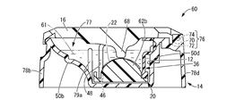
- the contact lens case 60 has a structure capable of performing a sterilization process using a hydrogen peroxide solution 61.
- members and parts having the same structure as in the first embodiment are denoted by the same reference numerals as those in the first embodiment in the drawings, and the description thereof is omitted as appropriate.
- FIGS. 9 to 13 the contact lens 22 accommodated in the contact lens case 60 and the hydrogen peroxide solution 61 as a liquid agent are indicated by phantom lines, and in FIG. The defense wall 79 is not shown in FIG.
- the shape of the lens holding body 20 and the container body 14 is different from that of the contact lens case 10 of the first embodiment. More specifically, the lens holding body 20 has a substantially longitudinal rectangular shape in plan view, and a pair of lens mounting portions 62a and 62b are provided at both ends in the longitudinal direction. In addition, a pair of catalyst holding walls 64 and 64 are formed between the pair of lens mounting portions in the center portion in the longitudinal direction of the lens holding body 20, and platinum or the like is formed between the catalyst holding walls 64 and 64. The metal catalyst 66 is inserted into the lens holder 20 to be positioned and held. Note that the lid body 16 of the container body 14 is also provided with a pair of pressing protrusions 68 and 68 at positions corresponding to the pair of lens placement portions 62a and 62b.
- the metal catalyst 66 held at the substantially central portion of the lens holding body 20 has a substantially rectangular block shape, and a pair of engaging protrusions are formed on the side surface facing the catalyst holding walls 64 and 64. 65 and 65 project (see FIG. 14).
- the engagement protrusions 65 and 65 are fitted into the housing concave grooves 67 and 67 provided in the catalyst holding walls 64 and 64 from above, so that the metal catalyst 66 is positioned and held between the catalyst holding walls 64 and 64. ing.
- the pair of lens mounting portions 62a and 62b provided on the lens holding body 20 are raised in a partially spherical shell shape that protrudes upward from the base member 26, as in the above-described embodiment.
- through holes 30 and 30 extending from the outer peripheral edge portion to the center inward in the radial direction extend in the vertical direction.
- the lens holding body 20 is provided with protective walls 34b and 34b at positions facing the center portions of the lens mounting portions 62a and 62b in the side edge portion 32b of the base member 26, respectively.
- a base end portion 38 of a connecting member 36 that connects the lid body 16 and the lens holding body 20 is fixed to the side edge portion 32d of the base member 26 at a central portion in the length direction. Further, a pair of protective walls 69, 69 extending from both side edge portions of the base end portion 38 toward both sides in the length direction are extended.
- the lens holding body 20 having such a structure is coupled to the lid body 16 of the container main body 14 via a coupling member 36 as in the above embodiment.
- the housing recess 12 of the container body 14 has a bottomed long rectangular cylindrical shape having a size capable of housing the lens holder 20 having a substantially long rectangular shape including the pair of lens mounting portions 62a and 62b. ing.
- a flange portion 24 protrudes from the upper end portion of the side wall 50d of the container body 14, and a shaft portion 70 provided at a side edge portion of the lid body 16 has pins 74 at both end portions in the longitudinal direction of the flange portion 24.
- a bearing 72 that is pivotally supported is provided. By the cooperation of the shaft portion 70, the bearing 72, and the pin 74, a hinge portion 76 that connects the lid body 16 to the container body 14 so as to be freely opened and closed is configured.
- the outer peripheral side of the side walls 50a to 50d of the container body 14 is integrally provided with reinforcing walls 78a to 78d whose upper ends are connected to the side walls 50a to 50d and extend downward.
- the side wall 50 b extends so as to be inclined obliquely outward, and an extended region 77 is defined on the side wall 50 b side of the housing recess 12.
- the four defense walls 79a, 79a, 79b, 79b are protrudingly provided by the predetermined height toward upper direction. As shown in FIG.
- the defense walls 79 a and 79 a are connected to the side walls 50 a and 50 c of the container main body 14, and are parallel to the side edge portion 32 b of the lens holding body 20 and inside the container main body 14. Extends in length. Further, the defense walls 79b and 79b are located on both sides of the metal catalyst 66 in the intermediate region sandwiched between the defense walls 79a and 79a and extend in a direction orthogonal to the side edge portion 32b. Note that the gaps between adjacent defense walls 79 a, 79 b, 79 b, 79 a are made smaller than the diameter of the contact lens 22.
- the hydrogen peroxide solution 61 flows into the accommodation recess 12 from the gaps between the defense walls 79a, 79b, 79b, 79a. Even if the contact lens 22 falls into the extended region 77, the contact lens 22 abuts on one of the defense walls 79a, 79a, 79b, 79b, and the inside of the housing recess 12 Can be prevented from flowing.
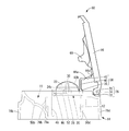
- FIGS. 1-10 A method of using the contact lens case 60 of this embodiment having such a structure will be described with reference to FIGS.
- the lid body 16 is rotated around the hinge portion 76 in the opening direction (right direction in FIG. 15). Move. At this time, the opening operation around the hinge portion 76 of the lid body 16 is performed so that the upper end portion 42 of the connecting member 36 is gradually extended by the bent portions 44a and 44b, so that the intermediate portion passes through the upper end portion 42 of the connecting member 36. It is transmitted as an external force that pulls 40 upward obliquely. Such an external force is transmitted also to the base member 26 of the lens holding body 20 to which the base end portion 38 of the connecting member 36 is fixed, and an external force that pulls up obliquely upward is applied to the entire lens holding body 20.
- the lens holding body 20 is moved to the hinge side via the connecting member 36. An external force that slides in the lateral direction to approach is transmitted. As a result, as shown in FIG. 15, the sliding protrusions 46, 46 of the lens holder 20 are fitted into the side grooves 52, 52 from the upper ends of the guide grooves 48, 48, and the lens holder 20. Is prevented from moving downward.
- the lens holder 20 is temporarily placed in the upper position of the receiving recess 12 at the same upper end as the guide grooves 48, 48. Temporary holding means for holding is configured.
- the lens mounting portions 62a and 62b of the lens holding body 20 are temporarily held at positions that protrude completely upward from the housing recess 12, the lens mounting portion.
- the attachment work of the contact lens 22 to 62a, 62b can be performed easily.
- the housing recess 12 is filled with the hydrogen peroxide solution 61 at this time, the contact between the hydrogen peroxide solution 61 and the user's finger can be avoided, and before the neutralization which is an irritant This prevents the hydrogen peroxide solution 61 from coming into contact with the user's finger or the risk of the hydrogen peroxide solution 61 coming into contact with the eye when the contact lens 22 is removed from the eye with the finger.
- the lens holding body 20 is provided with a pair of lens mounting portions 62a and 62b, the binocular lens mounting portions 62a and 62b are operated by opening and closing one lid body 16. As a result, the operability can be further improved. Further, the entire contact lens case 60 can be made compact and the number of parts can be reduced.
- the accommodation recess 12 is filled with the hydrogen peroxide solution 61.
- the side wall 50 b of the container body 14 is inclined obliquely outward to form the extended region 77. Accordingly, in order to fit the sliding protrusions 46, 46 of the lens holder 20 into the side grooves 52, the lens holder 20 is displaced to the hinge part 76 as a whole, and the side wall of the container body 14 is A large space is ensured between 50b and the lens holder 20. Thereby, the filling operation of the hydrogen peroxide solution 61 accommodated in the container 80 can be performed more easily from this space.
- the contact lens 22 is mounted on the lens mounting portions 62a and 62b, and after the hydrogen peroxide solution 61 is filled in the housing recess 12, the hinge portion is closed in the direction in which the lid 16 is closed (left direction in FIG. 15). Rotate around 76. As described above, the closing operation of the lid body 16 is transmitted to the base member 26 via the connecting member 36, and the sliding protrusions 46 and 46 are guided along the guide groove 48 from the side groove 52, so It is slid toward the bottom of the place 12.
- the lid body 16 is superimposed on the upper end surface of the container body 14, and the upper opening of the housing recess 12 is covered with the lid body 16, and the lens holding body 20 is It will be in the state accommodated and arrange
- the metal catalyst 66 is held by the lens holder 20, before the contact lens 22 is immersed in the hydrogen peroxide solution 61, the inside of the hydrogen peroxide solution 61 accommodated in the accommodation recess 12. The sum is reliably prevented from starting, and the sterilization treatment of the contact lens 22 with the hydrogen peroxide solution 61 can be performed efficiently.
- the lens mounting portions 62 a and 62 b are provided with a plurality of through holes 30, the hydrogen peroxide solution 61 is mounted on the surface of the lens mounting portion 28 through the through holes 30.
- the contact lens 22 is also brought into contact with the back surface side, and the entire surface of the contact lens 22 is stably sterilized.
- the presser protrusions 68 and 68 are opposed to each other with a gap above the lens placement portions 62a and 62b, the contact lenses 22 and 22 are caused by foaming due to the neutralization treatment of the hydrogen peroxide solution 61.
- the contact lenses 22 and 22 are displaced to the lens mounting portions 62a and 62b by contacting the presser protrusions 68 and 68, so that the lenses of the contact lenses 22 and 22 are displaced. Detachment from the mounting portions 62a and 62b is advantageously prevented.
- the lens mounting portions 28, 62a, and 62b provided on the lens holding body 20 may be configured by a hemispherical concave portion that protrudes downward, in addition to the partial spherical shell shape that protrudes upward.
- the shape, number, and position of the through holes 30 provided in the lens placement portions 28, 62a, and 62b can be arbitrarily set.
- a single through hole 30 may be provided with a length that does not reach the central portion from the outer peripheral edge, as shown in FIGS. 17 (b) and 17 (c).
- the position where the through hole 30 is provided may be obliquely crossed with respect to the extending direction of the hinge portions 18 and 76.
- a single circular through hole 30 may be provided in the central portion of the lens placement portions 28, 62a, 62b.
- the shape and arrangement of the through holes 30 may be performed in consideration of design properties.
- the shape of the connecting member 36 that connects the lens holding body 20 and the lid body 16 may be any shape as long as the rotation of the lid body 16 can be transmitted to the lens holding body 20. Any structure such as a rod-like elastic member that can be bent and deformed as a whole can be adopted.
- the connecting member 36 preferably includes a base end portion 38 and an intermediate portion 40 that rise upward from the lens holding body 20, but the upper end portion 42 has a structure that can be bent by bending portions 44a and 44b. The entire upper end portion 42 may be formed of a flexible piece that can be bent and deformed.
- the displacement restricting means is inserted into a through hole provided in the lens holder 20 by inserting a guide rod protruding upward from the bottom of the container main body 14.
- the thing etc. which regulate the raising / lowering displacement of the holding body 20 to an up-down direction may be sufficient.
- the temporary holding means for temporarily holding the lens holding body 20 in the upper position of the housing recess 12 is not limited to the illustrated one.
- the upper end portions of the guide grooves 48 and 48 can be deformed outwardly and deformed. It is also configured by a mechanism for temporarily holding the sliding protrusion 46 on the upper surface of the engaging protrusion by providing a mating protrusion and causing the sliding protrusion 46 to get over the engaging protrusion by rotating the lid body 16 greatly. Can do.
Landscapes
- Physics & Mathematics (AREA)
- Health & Medical Sciences (AREA)
- General Physics & Mathematics (AREA)
- Ophthalmology & Optometry (AREA)
- Optics & Photonics (AREA)
- Purses, Travelling Bags, Baskets, Or Suitcases (AREA)
- Eyeglasses (AREA)
Abstract
Priority Applications (5)
| Application Number | Priority Date | Filing Date | Title |
|---|---|---|---|
| CN201280074580.8A CN104427904B (zh) | 2012-07-09 | 隐形眼镜盒 | |
| US14/409,660 US9173464B2 (en) | 2012-07-09 | 2012-07-09 | Contact lens case |
| JP2013553176A JP5499226B1 (ja) | 2012-07-09 | 2012-07-09 | コンタクトレンズ用ケース |
| PCT/JP2012/004421 WO2014009987A1 (fr) | 2012-07-09 | 2012-07-09 | Étui pour lentille de contact |
| EP12880780.7A EP2870894B1 (fr) | 2012-07-09 | 2012-07-09 | Étui pour lentille de contact |
Applications Claiming Priority (1)
| Application Number | Priority Date | Filing Date | Title |
|---|---|---|---|
| PCT/JP2012/004421 WO2014009987A1 (fr) | 2012-07-09 | 2012-07-09 | Étui pour lentille de contact |
Publications (1)
| Publication Number | Publication Date |
|---|---|
| WO2014009987A1 true WO2014009987A1 (fr) | 2014-01-16 |
Family
ID=49915495
Family Applications (1)
| Application Number | Title | Priority Date | Filing Date |
|---|---|---|---|
| PCT/JP2012/004421 Ceased WO2014009987A1 (fr) | 2012-07-09 | 2012-07-09 | Étui pour lentille de contact |
Country Status (4)
| Country | Link |
|---|---|
| US (1) | US9173464B2 (fr) |
| EP (1) | EP2870894B1 (fr) |
| JP (1) | JP5499226B1 (fr) |
| WO (1) | WO2014009987A1 (fr) |
Cited By (4)
| Publication number | Priority date | Publication date | Assignee | Title |
|---|---|---|---|---|
| JP2014230613A (ja) * | 2013-05-28 | 2014-12-11 | ニプロ株式会社 | コンタクトレンズ用容器 |
| KR101658216B1 (ko) * | 2015-07-03 | 2016-09-20 | 박영상 | 다기능 렌즈 케이스 |
| WO2019167147A1 (fr) * | 2018-02-27 | 2019-09-06 | 株式会社メニコン | Étui de dispositif oculaire et kit de solution de traitement doté de l'étui de dispositif oculaire |
| WO2021038703A1 (fr) * | 2019-08-26 | 2021-03-04 | 株式会社メニコン | Boîtier de dispositif pour les yeux et recharge utilisée pour ledit boîtier de dispositif pour les yeux |
Families Citing this family (13)
| Publication number | Priority date | Publication date | Assignee | Title |
|---|---|---|---|---|
| SG11201702859WA (en) * | 2014-11-25 | 2017-06-29 | Novartis Ag | Cuvette system and methods for the inspection of ophthalmic lenses |
| KR200490803Y1 (ko) * | 2018-04-09 | 2020-02-20 | 주식회사 렌즈미 | 콘택트렌즈 보관 및 진열용 용기 |
| US11253035B2 (en) | 2019-01-22 | 2022-02-22 | Coopervision International Holding Company, Lp | Blister package for contact lens |
| US11136176B2 (en) * | 2019-01-22 | 2021-10-05 | Coopervision International Limited | Contact lens blister package with lens cradle |
| AU2019202027B2 (en) * | 2019-03-13 | 2020-12-03 | Pujiang Yilin Glasses Co., Ltd. | A contact lens box convenient to take |
| US12414615B2 (en) | 2020-12-13 | 2025-09-16 | Johnson & Johnson Vision Care, Inc. | Contact lens packages and methods of opening |
| CA3173598A1 (fr) * | 2021-09-13 | 2023-03-13 | Johnson & Johnson Vision Care, Inc. | Emballages de verres de contact et methodes de manutention et de fabrication |
| US12503289B2 (en) | 2021-12-16 | 2025-12-23 | Johnson & Johnson Vision Care, Inc. | Pressurized or vacuum-sealed contact lens packages |
| USD1061023S1 (en) | 2022-06-21 | 2025-02-11 | Johnson & Johnson Vision Care, Inc. | Contact lens package |
| USD1062223S1 (en) | 2022-06-21 | 2025-02-18 | Johnson & Johnson Vision Care, Inc. | Contact lens package |
| US12064018B2 (en) | 2022-09-27 | 2024-08-20 | Johnson & Johnson Vision Care, Inc. | Contact lens package with draining port |
| US12187522B2 (en) | 2023-01-13 | 2025-01-07 | Johnson & Johnson Vision Care, Inc. | Contact lens packages having an absorbent member |
| KR102787319B1 (ko) * | 2023-09-05 | 2025-03-26 | 국립금오공과대학교 산학협력단 | 콘택트렌즈 케이스 |
Citations (5)
| Publication number | Priority date | Publication date | Assignee | Title |
|---|---|---|---|---|
| JP2002006274A (ja) | 2000-06-26 | 2002-01-09 | Nof Corp | コンタクトレンズ保存容器 |
| JP2002526203A (ja) | 1998-09-21 | 2002-08-20 | エムディーエルイー メディカル デバイス ラボラトリーズ ヨーロッパ ゲーエムベーハー | コンタクトレンズのケア用装置 |
| WO2005039347A2 (fr) * | 2003-10-22 | 2005-05-06 | Novartis Ag | Logement de lentille de contact |
| GB2439625A (en) * | 2006-11-03 | 2008-01-02 | Alastair Knox | A contact lens safety apparatus |
| WO2008120954A1 (fr) * | 2007-04-02 | 2008-10-09 | Dong-Won Kang | Boîtier de stockage de lentille de contact |
Family Cites Families (3)
| Publication number | Priority date | Publication date | Assignee | Title |
|---|---|---|---|---|
| JPH06205706A (ja) * | 1992-12-09 | 1994-07-26 | Ciba Geigy Ag | コンタクトレンズケース |
| ES2436690T3 (es) * | 2007-02-07 | 2014-01-03 | Atrion Medical Products, Inc. | Estuche para lentes de contacto mejorado |
| US20100106128A1 (en) * | 2008-10-23 | 2010-04-29 | Shane Mao | Contact lens cases for delivery of ophthalmic agents |
-
2012
- 2012-07-09 WO PCT/JP2012/004421 patent/WO2014009987A1/fr not_active Ceased
- 2012-07-09 JP JP2013553176A patent/JP5499226B1/ja active Active
- 2012-07-09 US US14/409,660 patent/US9173464B2/en active Active
- 2012-07-09 EP EP12880780.7A patent/EP2870894B1/fr active Active
Patent Citations (5)
| Publication number | Priority date | Publication date | Assignee | Title |
|---|---|---|---|---|
| JP2002526203A (ja) | 1998-09-21 | 2002-08-20 | エムディーエルイー メディカル デバイス ラボラトリーズ ヨーロッパ ゲーエムベーハー | コンタクトレンズのケア用装置 |
| JP2002006274A (ja) | 2000-06-26 | 2002-01-09 | Nof Corp | コンタクトレンズ保存容器 |
| WO2005039347A2 (fr) * | 2003-10-22 | 2005-05-06 | Novartis Ag | Logement de lentille de contact |
| GB2439625A (en) * | 2006-11-03 | 2008-01-02 | Alastair Knox | A contact lens safety apparatus |
| WO2008120954A1 (fr) * | 2007-04-02 | 2008-10-09 | Dong-Won Kang | Boîtier de stockage de lentille de contact |
Non-Patent Citations (1)
| Title |
|---|
| See also references of EP2870894A4 * |
Cited By (8)
| Publication number | Priority date | Publication date | Assignee | Title |
|---|---|---|---|---|
| JP2014230613A (ja) * | 2013-05-28 | 2014-12-11 | ニプロ株式会社 | コンタクトレンズ用容器 |
| KR101658216B1 (ko) * | 2015-07-03 | 2016-09-20 | 박영상 | 다기능 렌즈 케이스 |
| WO2019167147A1 (fr) * | 2018-02-27 | 2019-09-06 | 株式会社メニコン | Étui de dispositif oculaire et kit de solution de traitement doté de l'étui de dispositif oculaire |
| WO2021038703A1 (fr) * | 2019-08-26 | 2021-03-04 | 株式会社メニコン | Boîtier de dispositif pour les yeux et recharge utilisée pour ledit boîtier de dispositif pour les yeux |
| JP6892564B1 (ja) * | 2019-08-26 | 2021-06-23 | 株式会社メニコン | 眼用デバイスケースおよび該眼用デバイスケースに用いられる補充容器 |
| JP2021142341A (ja) * | 2019-08-26 | 2021-09-24 | 株式会社メニコン | 眼用デバイスケースおよび該眼用デバイスケースに用いられる補充容器 |
| JP7405793B2 (ja) | 2019-08-26 | 2023-12-26 | 株式会社メニコン | 眼用デバイスケースおよび該眼用デバイスケースに用いられる補充容器 |
| US12029823B2 (en) | 2019-08-26 | 2024-07-09 | Menicon Co., Ltd. | Ocular device case and refill container used for the ocular device case |
Also Published As
| Publication number | Publication date |
|---|---|
| JP5499226B1 (ja) | 2014-05-21 |
| EP2870894A1 (fr) | 2015-05-13 |
| EP2870894B1 (fr) | 2017-02-01 |
| JPWO2014009987A1 (ja) | 2016-06-02 |
| US20150150346A1 (en) | 2015-06-04 |
| EP2870894A4 (fr) | 2016-02-24 |
| CN104427904A (zh) | 2015-03-18 |
| US9173464B2 (en) | 2015-11-03 |
Similar Documents
| Publication | Publication Date | Title |
|---|---|---|
| JP5499226B1 (ja) | コンタクトレンズ用ケース | |
| EP1677642B1 (fr) | Logement de lentille de contact | |
| EP0389418B1 (fr) | Unité de support de lentilles de contact avec paniers de support de lentilles retournables | |
| ES2436690T3 (es) | Estuche para lentes de contacto mejorado | |
| JP5615942B2 (ja) | コンタクトレンズケース | |
| JP5750794B2 (ja) | 点眼補助具 | |
| WO2003053229A3 (fr) | Speculum oculaire | |
| CN104427904B (zh) | 隐形眼镜盒 | |
| JP2014157172A (ja) | コンタクトレンズ保存ケース | |
| JP2024015397A (ja) | 眼用デバイスケースおよび該眼用デバイスケースに用いられる補充容器 | |
| JP2014157171A (ja) | コンタクトレンズ保存ケース | |
| JPWO2013140452A1 (ja) | コンタクトレンズ保存ケース | |
| WO2019167147A1 (fr) | Étui de dispositif oculaire et kit de solution de traitement doté de l'étui de dispositif oculaire | |
| KR20190028071A (ko) | 생리컵 케이스 | |
| WO2014009988A1 (fr) | Boîte de stérilisation de lentilles de contact | |
| JP6763751B2 (ja) | ハードコンタクトレンズ用収納ケース | |
| JP5903006B2 (ja) | コンタクトレンズ吸着具 | |
| KR20170085701A (ko) | 물티슈 용기 | |
| JPH0731773Y2 (ja) | 眼内レンズケース | |
| JP2003102763A (ja) | コンタクトレンズの取り外し具 | |
| JP2006110366A (ja) | 消毒用容器 | |
| JP2004261504A (ja) | 化粧料容器 |
Legal Events
| Date | Code | Title | Description |
|---|---|---|---|
| ENP | Entry into the national phase |
Ref document number: 2013553176 Country of ref document: JP Kind code of ref document: A |
|
| 121 | Ep: the epo has been informed by wipo that ep was designated in this application |
Ref document number: 12880780 Country of ref document: EP Kind code of ref document: A1 |
|
| WWE | Wipo information: entry into national phase |
Ref document number: 14409660 Country of ref document: US |
|
| REEP | Request for entry into the european phase |
Ref document number: 2012880780 Country of ref document: EP |
|
| WWE | Wipo information: entry into national phase |
Ref document number: 2012880780 Country of ref document: EP |
|
| NENP | Non-entry into the national phase |
Ref country code: DE |