WO2014010093A1 - Pneu - Google Patents
Pneu Download PDFInfo
- Publication number
- WO2014010093A1 WO2014010093A1 PCT/JP2012/068027 JP2012068027W WO2014010093A1 WO 2014010093 A1 WO2014010093 A1 WO 2014010093A1 JP 2012068027 W JP2012068027 W JP 2012068027W WO 2014010093 A1 WO2014010093 A1 WO 2014010093A1
- Authority
- WO
- WIPO (PCT)
- Prior art keywords
- tire
- belt
- width
- layer
- pair
- Prior art date
- Legal status (The legal status is an assumption and is not a legal conclusion. Google has not performed a legal analysis and makes no representation as to the accuracy of the status listed.)
- Ceased
Links
Images


Classifications
-
- B—PERFORMING OPERATIONS; TRANSPORTING
- B60—VEHICLES IN GENERAL
- B60C—VEHICLE TYRES; TYRE INFLATION; TYRE CHANGING; CONNECTING VALVES TO INFLATABLE ELASTIC BODIES IN GENERAL; DEVICES OR ARRANGEMENTS RELATED TO TYRES
- B60C9/00—Reinforcements or ply arrangement of pneumatic tyres
- B60C9/18—Structure or arrangement of belts or breakers, crown-reinforcing or cushioning layers
- B60C9/20—Structure or arrangement of belts or breakers, crown-reinforcing or cushioning layers built-up from rubberised plies each having all cords arranged substantially parallel
-
- B—PERFORMING OPERATIONS; TRANSPORTING
- B60—VEHICLES IN GENERAL
- B60C—VEHICLE TYRES; TYRE INFLATION; TYRE CHANGING; CONNECTING VALVES TO INFLATABLE ELASTIC BODIES IN GENERAL; DEVICES OR ARRANGEMENTS RELATED TO TYRES
- B60C11/00—Tyre tread bands; Tread patterns; Anti-skid inserts
- B60C11/03—Tread patterns
- B60C11/0327—Tread patterns characterised by special properties of the tread pattern
- B60C11/0332—Tread patterns characterised by special properties of the tread pattern by the footprint-ground contacting area of the tyre tread
-
- B—PERFORMING OPERATIONS; TRANSPORTING
- B60—VEHICLES IN GENERAL
- B60C—VEHICLE TYRES; TYRE INFLATION; TYRE CHANGING; CONNECTING VALVES TO INFLATABLE ELASTIC BODIES IN GENERAL; DEVICES OR ARRANGEMENTS RELATED TO TYRES
- B60C3/00—Tyres characterised by the transverse section
-
- B—PERFORMING OPERATIONS; TRANSPORTING
- B60—VEHICLES IN GENERAL
- B60C—VEHICLE TYRES; TYRE INFLATION; TYRE CHANGING; CONNECTING VALVES TO INFLATABLE ELASTIC BODIES IN GENERAL; DEVICES OR ARRANGEMENTS RELATED TO TYRES
- B60C5/00—Inflatable pneumatic tyres or inner tubes
- B60C5/12—Inflatable pneumatic tyres or inner tubes without separate inflatable inserts, e.g. tubeless tyres with transverse section open to the rim
-
- B—PERFORMING OPERATIONS; TRANSPORTING
- B60—VEHICLES IN GENERAL
- B60C—VEHICLE TYRES; TYRE INFLATION; TYRE CHANGING; CONNECTING VALVES TO INFLATABLE ELASTIC BODIES IN GENERAL; DEVICES OR ARRANGEMENTS RELATED TO TYRES
- B60C9/00—Reinforcements or ply arrangement of pneumatic tyres
- B60C9/02—Carcasses
- B60C9/0292—Carcass ply curvature
-
- B—PERFORMING OPERATIONS; TRANSPORTING
- B60—VEHICLES IN GENERAL
- B60C—VEHICLE TYRES; TYRE INFLATION; TYRE CHANGING; CONNECTING VALVES TO INFLATABLE ELASTIC BODIES IN GENERAL; DEVICES OR ARRANGEMENTS RELATED TO TYRES
- B60C9/00—Reinforcements or ply arrangement of pneumatic tyres
- B60C9/18—Structure or arrangement of belts or breakers, crown-reinforcing or cushioning layers
- B60C9/1835—Rubber strips or cushions at the belt edges
- B60C9/185—Rubber strips or cushions at the belt edges between adjacent or radially below the belt plies
-
- B—PERFORMING OPERATIONS; TRANSPORTING
- B60—VEHICLES IN GENERAL
- B60C—VEHICLE TYRES; TYRE INFLATION; TYRE CHANGING; CONNECTING VALVES TO INFLATABLE ELASTIC BODIES IN GENERAL; DEVICES OR ARRANGEMENTS RELATED TO TYRES
- B60C9/00—Reinforcements or ply arrangement of pneumatic tyres
- B60C9/18—Structure or arrangement of belts or breakers, crown-reinforcing or cushioning layers
- B60C9/20—Structure or arrangement of belts or breakers, crown-reinforcing or cushioning layers built-up from rubberised plies each having all cords arranged substantially parallel
- B60C9/2003—Structure or arrangement of belts or breakers, crown-reinforcing or cushioning layers built-up from rubberised plies each having all cords arranged substantially parallel characterised by the materials of the belt cords
- B60C9/2006—Structure or arrangement of belts or breakers, crown-reinforcing or cushioning layers built-up from rubberised plies each having all cords arranged substantially parallel characterised by the materials of the belt cords consisting of steel cord plies only
-
- B—PERFORMING OPERATIONS; TRANSPORTING
- B60—VEHICLES IN GENERAL
- B60C—VEHICLE TYRES; TYRE INFLATION; TYRE CHANGING; CONNECTING VALVES TO INFLATABLE ELASTIC BODIES IN GENERAL; DEVICES OR ARRANGEMENTS RELATED TO TYRES
- B60C9/00—Reinforcements or ply arrangement of pneumatic tyres
- B60C9/18—Structure or arrangement of belts or breakers, crown-reinforcing or cushioning layers
- B60C9/28—Structure or arrangement of belts or breakers, crown-reinforcing or cushioning layers characterised by the belt or breaker dimensions or curvature relative to carcass
-
- B—PERFORMING OPERATIONS; TRANSPORTING
- B60—VEHICLES IN GENERAL
- B60C—VEHICLE TYRES; TYRE INFLATION; TYRE CHANGING; CONNECTING VALVES TO INFLATABLE ELASTIC BODIES IN GENERAL; DEVICES OR ARRANGEMENTS RELATED TO TYRES
- B60C11/00—Tyre tread bands; Tread patterns; Anti-skid inserts
- B60C11/03—Tread patterns
- B60C11/04—Tread patterns in which the raised area of the pattern consists only of continuous circumferential ribs, e.g. zig-zag
-
- B—PERFORMING OPERATIONS; TRANSPORTING
- B60—VEHICLES IN GENERAL
- B60C—VEHICLE TYRES; TYRE INFLATION; TYRE CHANGING; CONNECTING VALVES TO INFLATABLE ELASTIC BODIES IN GENERAL; DEVICES OR ARRANGEMENTS RELATED TO TYRES
- B60C11/00—Tyre tread bands; Tread patterns; Anti-skid inserts
- B60C11/0008—Tyre tread bands; Tread patterns; Anti-skid inserts characterised by the tread rubber
- B60C2011/0016—Physical properties or dimensions
- B60C2011/0033—Thickness of the tread
-
- B—PERFORMING OPERATIONS; TRANSPORTING
- B60—VEHICLES IN GENERAL
- B60C—VEHICLE TYRES; TYRE INFLATION; TYRE CHANGING; CONNECTING VALVES TO INFLATABLE ELASTIC BODIES IN GENERAL; DEVICES OR ARRANGEMENTS RELATED TO TYRES
- B60C2200/00—Tyres specially adapted for particular applications
- B60C2200/06—Tyres specially adapted for particular applications for heavy duty vehicles
-
- Y—GENERAL TAGGING OF NEW TECHNOLOGICAL DEVELOPMENTS; GENERAL TAGGING OF CROSS-SECTIONAL TECHNOLOGIES SPANNING OVER SEVERAL SECTIONS OF THE IPC; TECHNICAL SUBJECTS COVERED BY FORMER USPC CROSS-REFERENCE ART COLLECTIONS [XRACs] AND DIGESTS
- Y02—TECHNOLOGIES OR APPLICATIONS FOR MITIGATION OR ADAPTATION AGAINST CLIMATE CHANGE
- Y02T—CLIMATE CHANGE MITIGATION TECHNOLOGIES RELATED TO TRANSPORTATION
- Y02T10/00—Road transport of goods or passengers
- Y02T10/80—Technologies aiming to reduce greenhouse gasses emissions common to all road transportation technologies
- Y02T10/86—Optimisation of rolling resistance, e.g. weight reduction
Definitions
- the present invention relates to a pneumatic tire, and more particularly to a pneumatic tire that can improve uneven wear resistance of the tire.
- Low-flat heavy-duty tires that are single-mounted on trucks, buses, etc. have a circumferential reinforcement layer on the belt layer, which suppresses tire diameter growth in the center region and reduces the contact pressure distribution in the tire width direction. Uniformity improves the uneven wear resistance of the tire.
- Patent Documents 1 to 3 techniques described in Patent Documents 1 to 3 are known.
- An object of the present invention is to provide a pneumatic tire that can improve uneven wear resistance of the tire.
- a pneumatic tire according to the present invention includes a carcass layer, a belt layer disposed on the outer side in the tire radial direction of the carcass layer, and a tread rubber disposed on the outer side in the tire radial direction of the belt layer.
- a pair of crossed belts having a belt angle of 10 [deg] or more and 45 [deg] or less in absolute value and mutually different signs, and a tire circumference.
- a circumferential reinforcing layer having a belt angle within a range of ⁇ 5 [deg] with respect to the direction is laminated, and the tread width TW and the total tire width SW are 0.79 ⁇ TW / SW ⁇ 0.
- the position diameter Yc and Characterized by having a relation of 0.80 ⁇ Yc / Ya ⁇ 0.90 and 0.95 ⁇ Yb / Ya ⁇ 1.00.
- a pneumatic tire according to the present invention includes a carcass layer, a belt layer disposed on the outer side in the tire radial direction of the carcass layer, and a tread rubber disposed on the outer side in the tire radial direction of the belt layer.
- the belt layer has a belt angle of 10 [deg] or more and 45 [deg] or less in absolute value, and a pair of cross belts having mutually different signs, and ⁇
- a circumferential reinforcing layer having a belt angle within a range of 5 [deg] is laminated, and the tread width TW and the cross-sectional width Wca of the carcass layer are 0.82 ⁇ TW / Wca ⁇ 0.92.
- the diameter Ya of the maximum height position of the carcass layer, the diameter Yb of the height position of the carcass layer at the end of the circumferential reinforcing layer, and the maximum width position of the carcass layer Diameter Yc is It characterized in that it has a relationship of 0.80 ⁇ Yc / Ya ⁇ 0.90 and 0.95 ⁇ Yb / Ya ⁇ 1.00.
- the belt layer has the circumferential reinforcing layer, the radial growth of the tire in the center region is suppressed. Further, when the ratios TW / SW, Yc / Ya, and Yb / Ya are within the above ranges, the diameter growth of the left and right shoulder portions is suppressed. Then, the difference in diameter growth between the center region and the shoulder region is further alleviated, and the contact pressure distribution of the tire is made uniform. Thereby, there is an advantage that the uneven wear resistance of the tire is improved.
- the ratio TW / Wca is within the above range, the difference in diameter growth between the center region and the shoulder region is alleviated, and the contact pressure distribution in the tire width direction is uniform. It becomes. Thereby, there is an advantage that the uneven wear resistance of the tire is improved.
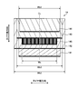
- FIG. 1 is a sectional view in the tire meridian direction showing a pneumatic tire according to an embodiment of the present invention.
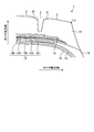
- FIG. 2 is an explanatory view showing a belt layer of the pneumatic tire shown in FIG.
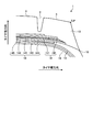
- FIG. 3 is an explanatory view showing a belt layer of the pneumatic tire shown in FIG. 1.
- FIG. 4 is an explanatory view showing the operation of the pneumatic tire shown in FIG.
- FIG. 5 is an explanatory view showing a modified example of the pneumatic tire shown in FIG. 1.
- FIG. 6 is an explanatory view showing a modified example of the pneumatic tire shown in FIG. 1.
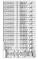
- FIG. 7 is a chart showing the results of the performance test of the pneumatic tire according to the embodiment of the present invention.
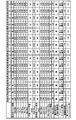
- FIG. 8 is a chart showing the results of the performance test of the pneumatic tire according to the embodiment of the present invention.
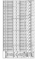
- FIG. 9 is a chart showing the results of the performance test of the pneumatic tire according to the embodiment of the present invention.
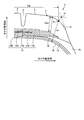
- FIG. 10 is an explanatory view showing a shoulder portion having a round shape.
- FIG. 1 is a sectional view in the tire meridian direction showing a pneumatic tire according to an embodiment of the present invention.
- FIG. 1 shows a heavy duty radial tire used for a truck, a bus, etc. for long-distance transportation.
- Reference sign CL is a tire equator plane.
- the tread end P and the tire ground contact end T coincide.
- the circumferential reinforcing layer 145 is hatched.
- the pneumatic tire 1 includes a pair of bead cores 11, 11, a pair of bead fillers 12, 12, a carcass layer 13, a belt layer 14, a tread rubber 15, a pair of sidewall rubbers 16, 16, and a pair. Rim cushion rubbers 17 and 17 (see FIG. 1).
- the pair of bead cores 11 and 11 has an annular structure and constitutes the core of the left and right bead portions.
- the pair of bead fillers 12 and 12 includes a lower filler 121 and an upper filler 122, which are disposed on the tire radial direction outer periphery of the pair of bead cores 11 and 11, respectively, to reinforce the bead portion.
- the carcass layer 13 is bridged in a toroidal shape between the left and right bead cores 11 and 11 to form a tire skeleton. Further, both ends of the carcass layer 13 are wound and locked from the inner side in the tire width direction to the outer side in the tire width direction so as to wrap the bead core 11 and the bead filler 12.
- the carcass layer 13 is formed by coating a plurality of carcass cords made of steel or an organic fiber material (for example, nylon, polyester, rayon, etc.) with a coating rubber and rolling them, and has an absolute value of 85 [deg] or more and 95. [Deg] The following carcass angle (inclination angle in the fiber direction of the carcass cord with respect to the tire circumferential direction).
- the belt layer 14 is formed by laminating a plurality of belt plies 141 to 145, and is arranged around the outer periphery of the carcass layer 13. A specific configuration of the belt layer 14 will be described later.
- the tread rubber 15 is disposed on the outer circumference in the tire radial direction of the carcass layer 13 and the belt layer 14 to constitute a tread portion of the tire.
- the pair of side wall rubbers 16 and 16 are respectively arranged on the outer side in the tire width direction of the carcass layer 13 to constitute left and right side wall portions.
- the pair of rim cushion rubbers 17 and 17 are arranged on the outer sides in the tire width direction of the left and right bead cores 11 and 11 and the bead fillers 12 and 12, respectively, and constitute left and right bead portions.
- the pneumatic tire 1 includes seven circumferential main grooves 2 extending in the tire circumferential direction and eight land portions 3 that are partitioned by these circumferential main grooves 2. I have.
- Each land portion 3 is a block that is divided in the tire circumferential direction by ribs that are continuous in the tire circumferential direction or lug grooves (not shown).
- FIG. 2 shows one side region of the tread portion with the tire equatorial plane CL as a boundary
- FIGS. the circumferential reinforcing layer 145 and the belt edge cushion 19 are hatched.
- the thin lines in the belt plies 141 to 145 schematically indicate the inclination of the belt cord.
- the belt layer 14 is formed by laminating a high-angle belt 141, a pair of cross belts 142 and 143, a belt cover 144, and a circumferential reinforcing layer 145, and is arranged around the outer periphery of the carcass layer 13. (See FIG. 2).
- the high-angle belt 141 is formed by coating a plurality of belt cords made of steel or organic fiber material with a coat rubber and rolling the belt, and an absolute value of a belt angle of 45 [deg] or more and 70 [deg] or less (tire circumferential direction). The inclination angle of the belt cord in the fiber direction). Further, the high-angle belt 141 is laminated and disposed on the outer side in the tire radial direction of the carcass layer 13.
- the pair of cross belts 142 and 143 is formed by rolling a plurality of belt cords made of steel or organic fiber material covered with a coat rubber, and has an absolute value of a belt angle of 10 [deg] or more and 45 [deg] or less. Have. Further, the pair of cross belts 142 and 143 have belt angles with different signs from each other, and are laminated so that the fiber directions of the belt cords cross each other (cross-ply structure).
- the cross belt 142 located on the inner side in the tire radial direction is called an inner diameter side cross belt
- the cross belt 143 located on the outer side in the tire radial direction is called an outer diameter side cross belt. Note that three or more cross belts may be laminated (not shown).
- the pair of cross belts 142 and 143 are disposed so as to be stacked on the outer side in the tire radial direction of the high-angle belt 141.
- the belt cover 144 is formed by rolling a plurality of belt cords made of steel or organic fiber material with a coating rubber, and has a belt angle of 10 [deg] or more and 45 [deg] or less in absolute value. Further, the belt cover 144 is disposed so as to be laminated on the outer side in the tire radial direction of the cross belts 142 and 143. In this embodiment, the belt cover 144 has the same belt angle as the outer diameter side crossing belt 143 and is disposed in the outermost layer of the belt layer 14.
- the circumferential reinforcing layer 145 is formed by winding a steel belt cord covered with a coat rubber in a spiral manner while inclining within a range of ⁇ 5 [deg] with respect to the tire circumferential direction. Further, the circumferential reinforcing layer 145 is disposed between the pair of cross belts 142 and 143. Further, the circumferential reinforcing layer 145 is disposed on the inner side in the tire width direction with respect to the left and right edge portions of the pair of cross belts 142 and 143. Specifically, one or more wires are spirally wound around the outer circumference of the inner diameter side crossing belt 142 to form the circumferential reinforcing layer 145. The circumferential reinforcing layer 145 reinforces the rigidity in the tire circumferential direction, so that the durability performance of the tire is improved.
- the belt layer 14 may have an edge cover (not shown).
- the edge cover is formed by rolling a plurality of belt cords made of steel or organic fiber material with a coating rubber, and has an absolute value of a belt angle of 0 [deg] or more and 5 [deg] or less.
- the edge covers are respectively disposed on the outer sides in the tire radial direction of the left and right edge portions of the outer diameter side cross belt 143 (or the inner diameter side cross belt 142). When these edge covers exhibit a tagging effect, the difference in diameter growth between the tread center region and the shoulder region is alleviated, and the uneven wear resistance performance of the tire is improved.
- the tire diameter growth is suppressed in the center region (the circumferential reinforcing layer arrangement region), while the left and right shoulder regions (the circumferential reinforcing layer arrangement). Outside the region), the rigidity in the tire circumferential direction becomes relatively small. For this reason, in the left and right shoulder regions, there is a problem that slippage of the tire ground contact surface increases and uneven wear occurs.
- this pneumatic tire 1 employs the following configuration in order to improve the uneven wear resistance of the tire (see FIGS. 1 to 3).
- the tread width TW and the total tire width SW have a relationship of 0.79 ⁇ TW / SW ⁇ 0.89.
- the tread width TW is a linear distance between the left and right tread ends P when a tire is mounted on a specified rim to apply a specified internal pressure and is in a no-load state.
- the tread end P is (1) a point having a square shoulder portion, which is a point of the edge portion.
- the tread end P and the tire ground contact end T coincide with each other because the shoulder portion has a square shape.
- the intersection P ′ between the profile of the tread portion and the profile of the sidewall portion is taken in the sectional view in the tire meridian direction.
- the leg of the perpendicular drawn from the intersection P ′ to the shoulder is defined as the tread end P.
- the tire ground contact end T is a tire when a tire is mounted on a specified rim and applied with a specified internal pressure, and is placed perpendicular to a flat plate in a stationary state and applied with a load corresponding to the specified load.
- the total tire width SW is the linear distance between the sidewalls (including all parts of the tire side pattern, characters, etc.) when the tire is mounted on the specified rim to provide the specified internal pressure and is in an unloaded state.
- the stipulated rim is an “applicable rim” defined in JATMA, a “Design Rim” defined in TRA, or a “Measuring Rim” defined in ETRTO.
- the specified internal pressure refers to the “maximum air pressure” specified by JATMA, the maximum value of “TIRE LOAD LIMITS AT VARIOUS COLD INFLATION PRESSURES” specified by TRA, or “INFLATION PRESSURES” specified by ETRTO.
- the specified load is the “maximum load capacity” specified in JATMA, the maximum value of “TIRE LOAD LIMITS AT VARIOUS COLD INFLATION PRESSURES” specified in TRA, or “LOAD CAPACITY” specified in ETRTO.
- the specified internal pressure is air pressure 180 [kPa]
- the specified load is 88 [%] of the maximum load capacity.
- the diameter Ya of the maximum height position of the carcass layer 13, the diameter Yb of the height position of the carcass layer 13 at the end of the circumferential reinforcing layer 145, and the diameter Yc of the maximum width position of the carcass layer 13 are 0. .80 ⁇ Yc / Ya ⁇ 0.90 and 0.95 ⁇ Yb / Ya ⁇ 1.00 (see FIG. 1).
- the diameter Ya of each position of the carcass layer 13 is measured as a no-load state while applying a specified internal pressure by mounting a tire on a specified rim.
- the diameter Ya at the maximum height position is measured as the distance from the tire rotation axis to the intersection of the tire equatorial plane CL and the carcass layer 13.
- the diameter Yb of the height position of the carcass layer 13 at the end of the circumferential reinforcing layer 145 is measured as the distance from the tire rotation axis at the foot of the perpendicular drawn from the end of the circumferential reinforcing layer 145 to the carcass layer 13. Is done.
- the diameter Yc at the maximum width position of the carcass layer 13 is measured as the distance from the tire rotation axis to the maximum width position of the carcass layer 13.
- the tread width TW and the cross-sectional width Wca of the carcass layer 13 have a relationship of 0.82 ⁇ TW / Wca ⁇ 0.92 (see FIG. 1). Thereby, the ratio TW / Wca is optimized.
- the cross-sectional width Wca of the carcass layer 13 refers to a linear distance between the left and right maximum width positions of the carcass layer 13 when a tire is mounted on a specified rim to apply a specified internal pressure and is in an unloaded state.
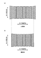
- FIG. 4 is an explanatory view showing the operation of the pneumatic tire shown in FIG.
- the (a) comparative example and (b) example of the figure all show the ground contact shape of the pneumatic tire 1 having a circumferential reinforcing layer.
- the ratios TW / SW, Yc / Ya, Yb / Ya, and TW / Wca are out of the above ranges, whereas in the example of FIG.
- the ratios TW / SW, Yc / Ya, Yb / Ya, and TW / Wca are within the above ranges.
- the belt layer has a circumferential reinforcing layer, thereby suppressing the tire diameter growth in the center region.
- the above ratios TW / SW, Yc / Ya, Yb / Ya, and TW / Wca are inappropriate, the diameter growth of the left and right shoulder portions is large, and the contact pressure distribution in the tire width direction is not uniform. . As a result, uneven wear may occur in the left and right shoulder portions.
- the radial growth of the center region is suppressed by the circumferential reinforcing layer 145, while the ratios TW / SW, Yc / Ya, Yb / Ya, TW / Wca are By being in the range, radial growth of the left and right shoulder portions is suppressed. Then, the diameter growth difference between the center region and the shoulder region is relaxed, and the contact pressure distribution of the tire is made uniform. Specifically, comparing FIG. 4A and FIG. 4B, it can be seen that in the configuration of FIG. This improves the uneven wear resistance of the tire.
- the circumferential reinforcing layer 145 is located on the inner side in the tire width direction than the left and right edge portions of the narrower cross belt 143 of the pair of cross belts 142 and 143. Preferably they are arranged.
- the width Ws of the circumferential reinforcing layer 145 is preferably in the range of 0.70 ⁇ Ws / TW ⁇ 0.90 with respect to the tread width TW.
- the ratio Ws / TW of the width Ws of the circumferential reinforcing layer 145 and the tread width TW is optimized.
- the width Ws of the circumferential reinforcing layer 145 is measured as a no-load state while applying a specified internal pressure by attaching the tire to a specified rim.
- the width Ws of the circumferential reinforcing layer 145 is the distance between the outermost ends of the divided portions.
- the cross-sectional width Wca of the carcass layer 13 is measured as a linear distance between the left and right maximum width positions of the carcass layer 13 when a tire is mounted on a specified rim to apply a specified internal pressure and is in an unloaded state.
- the width Wb2 of the wide cross belt 142 of the pair of cross belts 142 and 143 and the cross-sectional width Wca of the carcass layer 13 have a relationship of 0.79 ⁇ Wb2 / Wca ⁇ 0.89 ( FIG. 1 and FIG. 2). Thereby, the ratio Wb2 / Wca is optimized.
- the width Wb2 of the cross belt 142 is measured as a distance in the tire width direction when the tire is mounted on the specified rim to apply the specified internal pressure and the load is not loaded.
- the width Wb1 of the high-angle belt 141 and the width Wb3 of the narrower cross belt 143 of the pair of cross belts 142 and 143 preferably have a relationship of 0.85 ⁇ Wb1 / Wb3 ⁇ 1.05. (See FIG. 3). Thereby, the ratio Wb1 / Wb3 is optimized.
- the width Wb1 of the high-angle belt 141 is measured as a distance in the tire width direction when the tire is mounted on the specified rim to apply the specified internal pressure and the load is not loaded.
- the belt layer 14 has a bilaterally symmetric structure centered on the tire equatorial plane CL, and the cross belt is narrower than the width Wb ⁇ b> 1 of the high-angle belt 141.
- the width Wb3 of 143 has a relationship of Wb1 ⁇ Wb3.
- the edge part of the high angle belt 141 is arrange
- the present invention is not limited to this, and the width Wb1 of the high-angle belt 141 and the width Wb3 of the narrow cross belt 143 may have a relationship of Wb1 ⁇ Wb3 (not shown).
- the distance Gcc from the tread profile to the tire inner circumferential surface on the tire equatorial plane CL and the distance Gsh from the tread end P to the tire inner circumferential surface are 0.85 ⁇ Gsh / Gcc ⁇ A relationship of 1.10 is preferable, and a relationship of 0.90 ⁇ Gsh / Gcc ⁇ 1.00 is more preferable.
- the relationship between the gauge (distance Gcc) at the tire equatorial plane CL and the gauge (distance Gsh) at the tread end P is optimized.
- the distance Gcc is measured as a distance from the intersection of the tire equator plane CL and the tread profile to the intersection of the tire equator plane CL and the tire inner peripheral surface in a sectional view in the tire meridian direction. Therefore, in the configuration having the circumferential main groove 2 on the tire equatorial plane CL as in the configuration of FIGS. 1 and 2, the distance Gcc is measured excluding the circumferential main groove 2.
- the distance Gsh is measured as the length of a perpendicular line dropped from the tread end P to the tire inner peripheral surface in a sectional view in the tire meridian direction.
- the pneumatic tire 1 includes an inner liner 18 on the inner peripheral surface of the carcass layer 13, and the inner liner 18 is arranged over the entire inner peripheral surface of the tire.
- the distance Gcc and the distance Gsh are measured using the surface of the inner liner 18 as a reference (tire inner peripheral surface).
- the tread gauge Dcc on the tire equatorial plane CL and the tread gauge Dsh at the edge of the cross belt 143 on the outer side in the tire radial direction of the pair of cross belts 142 and 143 are 0.90 ⁇ Dsh / Dcc ⁇ 1. It is preferable to have 10 relationships (see FIG. 2). As a result, the relationship between the tread gauge (distance Dcc) on the tire equatorial plane CL and the tread gauge (distance Dsh) at the edge of the cross belt 143 on the outer side in the tire radial direction is optimized.
- the tread gauge Dcc on the tire equatorial plane CL is measured as a distance from the tread profile to the outermost belt ply (belt cover 144) of the belt layer 14.
- the tread gauge Dcc is a representative value of the thickness of the tread rubber 15 in the center region.
- the tread gauge Dcc is measured excluding the circumferential main groove 2.
- the tread gauge Dsh at the edge of the cross belt 143 is measured as the distance from the tread profile to the narrow cross belt 143.
- the tread gauge Dsh is a representative value of the thickness of the tread rubber 15 in the shoulder region.
- the tread gauge Dsh is measured excluding the circumferential main groove 2.
- the tread gauge Dsh makes a line perpendicular to the cross belt 143 from the edge of the cross belt 143. Pull towards the tread surface and measure the length.
- the outer diameter Hcc of the tread profile at the tire equatorial plane CL and the outer diameter Hsh of the tread profile at the tire ground contact edge T have a relationship of 0.010 ⁇ (Hcc ⁇ Hsh) /Hcc ⁇ 0.015. Preferred (see FIG. 2).
- the outer diameters Hcc and Hsh of the tread profile are measured as a no-load state while applying a specified internal pressure by mounting the tire on a specified rim.
- the tire ground contact end T is a tire when a tire is attached to a specified rim and applied with a specified internal pressure and is placed perpendicular to a flat plate in a stationary state and applied with a load corresponding to the specified load.
- the hardness of the tread rubber 15 is 60 or more (see FIG. 1). Thereby, the rigidity of the tread rubber 15 is ensured.
- the hardness of the tread rubber 15 is not particularly limited, but is restricted by the relationship with the tire function.
- Rubber hardness means JIS-A hardness according to JIS-K6263.
- the contact width Wcc of the land portion 3 closest to the tire equator plane CL and the contact width Wsh of the land portion 3 located on the outermost side in the tire width direction have a relationship of 0.90 ⁇ Wsh / Wcc ⁇ 1.20. It is preferable to have (refer FIG. 2). Thereby, the ground contact width Wcc of the land portion 3 in the center region and the ground contact width Wsh of the land portion 3 in the shoulder region are made uniform.
- ground contact widths Wcc and Wsh are measured as a no-load state while applying a specified internal pressure by mounting a tire on a specified rim.
- the belt cord of the high-angle belt 141 is a steel wire, and the high-angle belt has an end number of 15 [lines / 50 mm] or more and 25 [lines / 50 mm] or less (see FIG. 4).
- the belt cords of the pair of cross belts 142 and 143 are steel wires, and the pair of cross belts 142 and 143 have an end number of 18 [lines / 50 mm] or more and 28 [lines / 50 mm] or less.
- the belt cord of the circumferential reinforcing layer 145 is preferably a steel wire and has an end number of 17 [pieces / 50 mm] or more and 30 [pieces / 50 mm] or less. Thereby, the strength of each belt ply 141, 142, 143, 145 is ensured appropriately.
- the elongation at a tensile load of 100 [N] to 300 [N] is 1.0 [%] or more and 2.5 [%] or less.
- the elongation at a tensile load of 500 [N] to 1000 [N] is preferably 0.5 [%] or more and 2.0 [%] or less.
- Such a belt cord (high elongation steel wire) has a better elongation at low load than normal steel wire, and can withstand the load applied to the circumferential reinforcing layer 145 from the time of manufacture to the time of tire use. This is preferable in that damage to the circumferential reinforcing layer 145 can be suppressed.
- the elongation of the belt cord is measured according to JIS G3510.
- the width Wb3 of the narrow cross belt 143 and the width Ws of the circumferential reinforcing layer 145 have a relationship of 0.75 ⁇ Ws / Wb3 ⁇ 0.90. Thereby, the width Ws of the circumferential reinforcing layer 145 is appropriately secured.
- FIG. 5 is an explanatory view showing a modified example of the pneumatic tire shown in FIG. 1. This figure shows an enlarged cross-sectional view of the shoulder land portion.
- the land portion 3 located on the outermost side in the tire width direction has a chamfered portion 31 at the edge portion on the circumferential main groove 2 side.
- the chamfered portion 31 may be a C chamfer or a R chamfer formed continuously in the tire circumferential direction along the circumferential main groove 2 or a notch formed discontinuously in the tire circumferential direction. May be.
- the left and right land portions 3, 3 defined in the outermost circumferential main groove 2 are ribs, and each has a chamfered portion 31 at the edge on the outermost circumferential main groove 2 side. ing. Further, the chamfered portion 31 is a C chamfer and is continuously formed in the tire circumferential direction.
- FIG. 6 is an explanatory view showing a modified example of the pneumatic tire shown in FIG. 1. This figure shows an enlarged view of the end of the belt layer 14 on the outer side in the tire width direction. Further, in the same figure, the circumferential reinforcing layer 145 and the belt edge cushion 19 are hatched.
- the circumferential reinforcing layer 145 is disposed on the inner side in the tire width direction from the left and right edge portions of the narrow cross belt 143 of the pair of cross belts 142 and 143. Further, the belt edge cushion 19 is sandwiched and disposed at a position between the pair of cross belts 142 and 143 and corresponding to the edge portions of the pair of cross belts 142 and 143. Specifically, the belt edge cushion 19 is disposed on the outer side in the tire width direction of the circumferential reinforcing layer 145 and is adjacent to the circumferential reinforcing layer 145, and a pair of ends from the outer end of the circumferential reinforcing layer 145 in the tire width direction.
- the cross belts 142 and 143 are arranged so as to extend to the outer ends in the tire width direction.
- the belt edge cushion 19 has a structure thicker than the circumferential reinforcing layer 145 as a whole by increasing the thickness toward the outer side in the tire width direction. .
- the belt edge cushion 19 has a modulus E at 100% extension lower than the coat rubber of each cross belt 142, 143.
- the modulus E at 100% extension of the belt edge cushion 19 and the modulus Eco of the coat rubber have a relationship of 0.60 ⁇ E / Eco ⁇ 0.95.
- the belt edge cushion 19 has a two-color structure including a stress relaxation rubber 191 and an end relaxation rubber 192 in the configuration of FIG. 1.
- the stress relaxation rubber 191 is disposed between the pair of cross belts 142 and 143 and outside the circumferential reinforcing layer 145 in the tire width direction and is adjacent to the circumferential reinforcing layer 145.
- the end relaxation rubber 192 is disposed between the pair of cross belts 142 and 143, and is disposed on the outer side in the tire width direction of the stress relaxation rubber 191 and at a position corresponding to the edge portion of the pair of cross belts 142 and 143. Adjacent to rubber 191.
- the belt edge cushion 19 has a structure in which the stress relaxation rubber 191 and the end relaxation rubber 192 are continuously provided in the tire width direction in the tire meridian cross-sectional view, and the tire of the circumferential reinforcing layer 145 The region from the end portion on the outer side in the width direction to the edge portion of the pair of cross belts 142 and 143 is filled in.
- the modulus Ein of the stress relaxation rubber 191 when stretched 100% and the modulus Eco of the cross belts 142 and 143 when coated rubber 100% stretch has a relationship of Ein ⁇ Eco.
- the modulus Ein of the stress relaxation rubber 191 and the modulus Eco of the coat rubber have a relationship of 0.6 ⁇ Ein / Eco ⁇ 0.9.
- the modulus Ein at 100% elongation of the stress relaxation rubber 191 is preferably in the range of 4.0 [MPa] ⁇ Ein ⁇ 5.5 [MPa].
- the modulus Eout at 100% extension of the end relaxation rubber 192 and the modulus Ein at 100% extension of the stress relaxation rubber 191 have a relationship of Eout ⁇ Ein.
- the pneumatic tire 1 includes the carcass layer 13, the belt layer 14 disposed outside the carcass layer 13 in the tire radial direction, and the tread rubber 15 disposed outside the belt layer 14 in the tire radial direction. (See FIG. 1). Further, the belt layer 14 has a belt angle of 10 [deg] or more and 45 [deg] or less in absolute value, and a pair of cross belts 142 and 143 having mutually different belt angles, and the tire circumferential direction. A circumferential reinforcing layer 145 having a belt angle within a range of ⁇ 5 [deg] is laminated (see FIG. 3).
- the tread width TW and the tire total width SW have a relationship of 0.79 ⁇ TW / SW ⁇ 0.89 (see FIG. 1).
- the diameter Ya of the maximum height position of the carcass layer 13, the diameter Yb of the height position of the carcass layer 13 at the end of the circumferential reinforcing layer 145, and the diameter Yc of the maximum width position of the carcass layer 13 are 0. .80 ⁇ Yc / Ya ⁇ 0.90 and 0.95 ⁇ Yb / Ya ⁇ 1.00.
- the belt layer 14 includes the circumferential reinforcing layer 145, thereby suppressing the tire diameter growth in the center region. Further, when the ratios TW / SW, Yc / Ya, and Yb / Ya are within the above ranges, the diameter growth of the left and right shoulder portions is suppressed. Then, the difference in diameter growth between the center region and the shoulder region is further relaxed, and the contact pressure distribution of the tire is made uniform (see FIG. 4B). Thereby, there is an advantage that the uneven wear resistance of the tire is improved. Specifically, when 0.79 ⁇ TW / SW, the average contact pressure decreases.
- the tread width TW and the cross-sectional width Wca of the carcass layer 13 have a relationship of 0.82 ⁇ TW / Wca ⁇ 0.92 (see FIG. 1).
- the ratio TW / Wca is within the above range, the difference in diameter growth between the center region and the shoulder region is reduced (see FIG. 4B), and the contact pressure distribution in the tire width direction is reduced. It is made uniform.
- the uneven wear resistance of the tire is improved. That is, when 0.82 ⁇ TW / Wca, the average contact pressure decreases. Further, when TW / Wca ⁇ 0.92, rising of the shoulder portion is suppressed, and bending at the time of grounding is suppressed.
- the width Ws of the circumferential reinforcing layer 145 is within the range of 0.70 ⁇ Ws / TW ⁇ 0.90 with respect to the tread width TW (see FIG. 1).
- ratio Ws / TW of the width Ws of the circumferential direction reinforcement layer 145 and the tread width TW is optimized. That is, when 0.70 ⁇ Ws / TW, the contact pressure distribution of the tire is made uniform, and the uneven wear resistance of the tire is improved. Further, when Ws / TW ⁇ 0.90, fatigue rupture of the belt cord at the edge portion of the circumferential reinforcing layer 145 is suppressed.
- the width Wb3 of the narrow cross belt 143 and the width Ws of the circumferential reinforcing layer 145 are in the range of 0.75 ⁇ Ws / Wb3 ⁇ 0.90 (see FIG. 3). . Accordingly, there is an advantage that the width Ws of the circumferential reinforcing layer 145 is appropriately secured, and the effect of suppressing the radial growth of the center region by the circumferential reinforcing layer 145 is appropriately secured.
- the width Wb2 of the wide cross belt 142 of the pair of cross belts 142 and 143 and the cross-sectional width Wca of the carcass layer 13 are 0.79 ⁇ Wb2 / Wca ⁇ 0.89.
- the durability of the tire is further improved by the ratio Wb2 / Wca being within the above range. That is, when 0.79 ⁇ Wb2 / Wca, there is an advantage that tire diameter growth in the shoulder region is suppressed and the uneven wear resistance of the tire is improved. Further, when Wb2 / Wca ⁇ 0.89, fatigue rupture of the belt cord at the edge portion of the wide cross belt 142 is suppressed.
- the belt layer 14 includes a high-angle belt 141 having a belt angle of 45 [deg] or more and 70 [deg] or less in absolute value.
- a pair of cross belts 142 and 143 are disposed on the outer side in the tire radial direction of the high-angle belt 141, and a circumferential reinforcing layer 145 is disposed between the pair of cross belts 142 and 143 (see FIG. 3).
- 142 and 143 are disposed inside the tire in the tire radial direction or inside the tire radial direction of the high-angle belt 141 (not shown).
- the cross belt 142 on the inner side in the tire radial direction of the pair of cross belts 142 and 143 and the high-angle belt 141 have the same belt angle (see FIG. 3).
- the width Wb1 of the high-angle belt 141 and the width Wb3 of the narrower cross belt 143 of the pair of cross belts 142 and 143 are 0.85 ⁇ Wb1 / Wb3 ⁇ 1.05.
- the ratio Wb1 / Wb3 between the width Wb1 of the high-angle belt 141 and the width Wb3 of the narrow cross belt 143 is optimized, and the uneven wear resistance of the tire is improved.
- the distance Gcc from the tread profile to the tire inner circumferential surface on the tire equatorial plane CL and the distance Gsh from the tread end P to the tire inner circumferential surface are 0.85 ⁇ Gsh / Gcc ⁇ 1.10 relationship (see FIG. 2).
- the relationship between the gauge (distance Gcc) at the tire equatorial plane CL and the gauge (distance Gsh) at the tread end P is optimized.
- a tread gauge Dcc (a distance from the tread profile to the outermost belt ply (belt cover 144) of the belt layer 14) in the tire equatorial plane CL, a pair of cross belts 142,
- the tread gauge Dsh (the distance from the tread profile to the narrower cross belt 143 in FIG. 2) at the edge portion of the cross belt 143 on the outer side in the tire radial direction of 143 is 0.90 ⁇ Dsh / Dcc ⁇ 1. 10 relationships (see FIG. 2).
- the relationship between the tread gauge (distance Dcc) on the tire equatorial plane CL and the tread gauge (distance Dsh) at the edge portion of the cross belt 143 on the outer side in the tire radial direction is optimized.
- the outer diameter Hcc of the tread profile at the tire equatorial plane CL and the outer diameter Hsh of the tread profile at the tire ground contact edge T are 0.010 ⁇ (Hcc ⁇ Hsh) / Hcc ⁇ 0. 015 (see FIG. 2).
- the tread rubber 15 has a hardness of 60 or more (see FIG. 1). Thereby, there exists an advantage by which the rigidity of the tread rubber 15 is ensured.
- the pneumatic tire 1 includes a plurality of circumferential main grooves 2 extending in the tire circumferential direction and a plurality of land portions 3 defined by the circumferential main grooves 2 (see FIG. 1). . Further, the contact width Wcc of the land portion 3 closest to the tire equator plane CL and the contact width Wsh of the land portion 3 located on the outermost side in the tire width direction have a relationship of 0.90 ⁇ Wsh / Wcc ⁇ 1.20. Have. In such a configuration, the ground contact width Wcc of the land portion 3 in the center region and the ground contact width Wsh of the land portion 3 in the shoulder region are made uniform. Thereby, the contact pressure distribution in the tire width direction is optimized, and there is an advantage that the uneven wear resistance performance of the tire is improved.
- the outermost land portion 3 in the tire width direction has a chamfered portion 31 at the edge portion on the circumferential main groove 2 side (see FIG. 5).
- the circumferential direction main groove 2 side rib edge ground pressure of a shoulder land part can be reduced, and uneven wear resistance improves. There is an advantage.
- the belt cord of the circumferential reinforcing layer 145 is a steel wire and has an end number of 17 [pieces / 50 mm] or more and 30 [pieces / 50 mm] or less.
- the elongation at the time of a tensile load of 100 [N] to 300 [N] at the time of the belt cord member constituting the circumferential reinforcing layer 145 is 1.0 [%] or more and 2.5 [%]. It is the following. Thereby, there exists an advantage by which the suppression effect of the diameter growth of the center area
- the elongation of the belt cord constituting the circumferential reinforcing layer 145 at the time of a tensile load of 500 [N] to 1000 [N] is 0.5 [%] or more and 2.0 [%]. It is the following. Thereby, there exists an advantage by which the suppression effect of the diameter growth of the center area
- the circumferential reinforcing layer 145 is disposed on the inner side in the tire width direction from the left and right edge portions of the narrow cross belt 143 of the pair of cross belts 142 and 143 (see FIG. 3). ).
- the pneumatic tire 1 is disposed between the pair of cross belts 142 and 143 and on the outer side in the tire width direction of the circumferential reinforcing layer 145 and adjacent to the circumferential reinforcing layer 145, and a pair of An end portion relaxation rubber 192 disposed between the cross belts 142 and 143 and located outside the stress relaxation rubber 191 in the tire width direction and corresponding to the edge portions of the pair of cross belts 142 and 143 and adjacent to the stress relaxation rubber 191. (See FIG. 6).
- the circumferential reinforcing layer 145 is arranged on the inner side in the tire width direction with respect to the left and right edge portions of the narrow cross belt 143 of the pair of cross belts 142 and 143, so that the edge of the circumferential reinforcing layer 145 There is an advantage that fatigue rupture of the peripheral rubber in the part is suppressed. Further, since the stress relaxation rubber 191 is disposed on the outer side in the tire width direction of the circumferential reinforcing layer 145, the shear strain of the peripheral rubber between the edge portion of the circumferential reinforcing layer 145 and between the cross belts 142 and 143 is relaxed.
- the end relaxation rubber 192 is disposed at a position corresponding to the edge portions of the cross belts 142 and 143, the shear strain of the peripheral rubber at the edge portions of the cross belts 142 and 143 is reduced.
- the modulus Ein when the stress relaxation rubber 191 is stretched 100% and the modulus Eco when the coat rubber of the pair of cross belts 142 and 143 is stretched 100% have a relationship of Ein ⁇ Eco (FIG. 6).
- the modulus Ein of the stress relaxation rubber 191 is optimized, and there is an advantage that the shear strain of the peripheral rubber between the edge portion of the circumferential reinforcing layer 145 and the cross belts 142 and 143 is relaxed.
- the modulus Ein when the stress relaxation rubber 191 is stretched 100% and the modulus Eco when the coat rubber of the pair of cross belts 142 and 143 is stretched 100% are 0.6 ⁇ Ein / Eco ⁇ 0. .9 (see FIG. 6).
- the modulus Ein of the stress relaxation rubber 191 is optimized, and there is an advantage that the shear strain of the peripheral rubber between the edge portion of the circumferential reinforcing layer 145 and the cross belts 142 and 143 is relaxed.
- the modulus Ein at the time of 100% extension of the stress relaxation rubber 191 is in the range of 4.0 [MPa] ⁇ Ein ⁇ 5.5 [MPa] (see FIG. 6).
- the modulus Ein of the stress relaxation rubber 191 is optimized, and there is an advantage that the shear strain of the peripheral rubber between the edge portion of the circumferential reinforcing layer 145 and the cross belts 142 and 143 is relaxed.
- the pneumatic tire 1 is a heavy load having a flatness ratio of 40 [%] or more and 55 [%] or less in a state where the tire is assembled on a regular rim and a regular internal pressure and a regular load are applied to the tire. It is preferably applied to heavy duty tires.
- the heavy load tire has a larger load when the tire is used than the tire for a passenger car. For this reason, the radial difference between the arrangement region of the circumferential reinforcing layer and the region outside the circumferential direction of the circumferential reinforcing layer is likely to be large. Further, in a tire having a low flatness ratio as described above, the ground contact shape tends to be a drum shape. Therefore, the above-described uneven wear suppression effect can be remarkably obtained by using such a heavy load tire as an application target.
- 7 to 9 are tables showing the results of the performance test of the pneumatic tire according to the embodiment of the present invention.
- a pneumatic tire is mounted on a trailer shaft of a 6 ⁇ 4 tractor trailer that is a test vehicle. After the test vehicle travels 100,000 km, the wear amount of the edge portion of the shoulder land portion and the wear amount of the outermost circumferential main groove are measured, and the difference between them is calculated as the shoulder shoulder wear amount. Evaluation is performed. This evaluation is performed by index evaluation based on the conventional example (100), and the larger the value, the better. If the evaluation is 105 or more, it is superior to the conventional example, and if the evaluation is 110 or more, it can be said that a sufficient effect is obtained.
- the pneumatic tire 1 of Examples 1-41 has the configuration described in FIGS.
- the modulus at 100% elongation of the coated rubber of all the belt layers 14 is 6.0 [MPa].
- the conventional pneumatic tire does not have a circumferential reinforcing layer in the configuration shown in FIGS.
- the pneumatic tire of the comparative example has the configuration described in FIGS.
Landscapes
- Engineering & Computer Science (AREA)
- Mechanical Engineering (AREA)
- Tires In General (AREA)
Priority Applications (42)
| Application Number | Priority Date | Filing Date | Title |
|---|---|---|---|
| CN201280073450.2A CN104321206B (zh) | 2012-07-13 | 2012-07-13 | 充气轮胎 |
| DE112012006319.8T DE112012006319B4 (de) | 2012-07-13 | 2012-07-13 | Luftreifen |
| US14/404,316 US20150165822A1 (en) | 2012-07-13 | 2012-07-13 | Pneumatic Tire |
| KR1020157002886A KR101741054B1 (ko) | 2012-07-13 | 2012-07-13 | 공기입 타이어 |
| PCT/JP2012/068027 WO2014010093A1 (fr) | 2012-07-13 | 2012-07-13 | Pneu |
| JP2012542296A JP5182455B1 (ja) | 2012-07-13 | 2012-07-13 | 空気入りタイヤ |
| KR1020157002927A KR101741056B1 (ko) | 2012-07-13 | 2013-06-07 | 공기입 타이어 |
| CN201380030118.2A CN104379368B (zh) | 2012-07-13 | 2013-06-07 | 充气轮胎 |
| KR1020157003012A KR101741057B1 (ko) | 2012-07-13 | 2013-06-07 | 공기입 타이어 |
| DE112013002605.8T DE112013002605B4 (de) | 2012-07-13 | 2013-06-07 | Luftreifen |
| US14/406,180 US9259971B2 (en) | 2012-07-13 | 2013-06-07 | Pneumatic tire |
| KR1020157003142A KR101741061B1 (ko) | 2012-07-13 | 2013-06-07 | 공기입 타이어 |
| PCT/JP2013/065843 WO2014010349A1 (fr) | 2012-07-13 | 2013-06-07 | Pneumatique |
| CN201380030179.9A CN104395104B (zh) | 2012-07-13 | 2013-06-07 | 充气轮胎 |
| DE112013002470.5T DE112013002470B4 (de) | 2012-07-13 | 2013-06-07 | Luftreifen |
| US14/406,151 US9272578B2 (en) | 2012-07-13 | 2013-06-07 | Pneumatic tire |
| US14/405,357 US9604502B2 (en) | 2012-07-13 | 2013-06-07 | Pneumatic tire |
| DE112013002477.2T DE112013002477B4 (de) | 2012-07-13 | 2013-06-07 | Luftreifen |
| PCT/JP2013/065846 WO2014010351A1 (fr) | 2012-07-13 | 2013-06-07 | Pneumatique |
| JP2013526224A JP6299218B2 (ja) | 2012-07-13 | 2013-06-07 | 空気入りタイヤ |
| DE112013002550.7T DE112013002550B4 (de) | 2012-07-13 | 2013-06-07 | Luftreifen |
| PCT/JP2013/065851 WO2014010353A1 (fr) | 2012-07-13 | 2013-06-07 | Pneumatique |
| DE112013002467.5T DE112013002467B9 (de) | 2012-07-13 | 2013-06-07 | Luftreifen |
| PCT/JP2013/065845 WO2014010350A1 (fr) | 2012-07-13 | 2013-06-07 | Pneumatique |
| DE112013002546.9T DE112013002546B4 (de) | 2012-07-13 | 2013-06-07 | Luftreifen |
| CN201380030100.2A CN104349913B (zh) | 2012-07-13 | 2013-06-07 | 充气轮胎 |
| KR1020157003092A KR101741058B1 (ko) | 2012-07-13 | 2013-06-07 | 공기입 타이어 |
| CN201380030087.0A CN104349912B (zh) | 2012-07-13 | 2013-06-07 | 充气轮胎 |
| PCT/JP2013/065850 WO2014010352A1 (fr) | 2012-07-13 | 2013-06-07 | Pneumatique |
| KR1020157003228A KR101741063B1 (ko) | 2012-07-13 | 2013-06-07 | 공기입 타이어 |
| JP2013526225A JP6299219B2 (ja) | 2012-07-13 | 2013-06-07 | 空気入りタイヤ |
| PCT/JP2013/065842 WO2014010348A1 (fr) | 2012-07-13 | 2013-06-07 | Pneumatique |
| JP2013526222A JP6299216B2 (ja) | 2012-07-13 | 2013-06-07 | 空気入りタイヤ |
| CN201380029791.4A CN104379367B (zh) | 2012-07-13 | 2013-06-07 | 充气轮胎 |
| KR1020157003115A KR101741060B1 (ko) | 2012-07-13 | 2013-06-07 | 공기입 타이어 |
| JP2013526223A JP6299217B2 (ja) | 2012-07-13 | 2013-06-07 | 空気入りタイヤ |
| CN201380029739.9A CN104334369B (zh) | 2012-07-13 | 2013-06-07 | 充气轮胎 |
| US14/405,387 US9604503B2 (en) | 2012-07-13 | 2013-06-07 | Pneumatic tire |
| US14/405,146 US9849730B2 (en) | 2012-07-13 | 2013-06-07 | Pneumatic tire |
| US14/405,400 US9783003B2 (en) | 2012-07-13 | 2013-06-07 | Pneumatic tire |
| JP2013526229A JP6299221B2 (ja) | 2012-07-13 | 2013-06-07 | 空気入りタイヤ |
| JP2013526228A JP6299220B2 (ja) | 2012-07-13 | 2013-06-07 | 空気入りタイヤ |
Applications Claiming Priority (1)
| Application Number | Priority Date | Filing Date | Title |
|---|---|---|---|
| PCT/JP2012/068027 WO2014010093A1 (fr) | 2012-07-13 | 2012-07-13 | Pneu |
Publications (1)
| Publication Number | Publication Date |
|---|---|
| WO2014010093A1 true WO2014010093A1 (fr) | 2014-01-16 |
Family
ID=48481366
Family Applications (1)
| Application Number | Title | Priority Date | Filing Date |
|---|---|---|---|
| PCT/JP2012/068027 Ceased WO2014010093A1 (fr) | 2012-07-13 | 2012-07-13 | Pneu |
Country Status (6)
| Country | Link |
|---|---|
| US (1) | US20150165822A1 (fr) |
| JP (1) | JP5182455B1 (fr) |
| KR (1) | KR101741054B1 (fr) |
| CN (1) | CN104321206B (fr) |
| DE (1) | DE112012006319B4 (fr) |
| WO (1) | WO2014010093A1 (fr) |
Cited By (12)
| Publication number | Priority date | Publication date | Assignee | Title |
|---|---|---|---|---|
| JP2017030416A (ja) * | 2015-07-29 | 2017-02-09 | 東洋ゴム工業株式会社 | 空気入りタイヤ |
| JP2017030412A (ja) * | 2015-07-29 | 2017-02-09 | 東洋ゴム工業株式会社 | 空気入りタイヤ |
| JP2017030418A (ja) * | 2015-07-29 | 2017-02-09 | 東洋ゴム工業株式会社 | 空気入りタイヤ |
| JP2017030413A (ja) * | 2015-07-29 | 2017-02-09 | 東洋ゴム工業株式会社 | 空気入りタイヤ |
| JP2017030417A (ja) * | 2015-07-29 | 2017-02-09 | 東洋ゴム工業株式会社 | 空気入りタイヤ |
| JP2017533140A (ja) * | 2014-10-29 | 2017-11-09 | コンパニー ゼネラール デ エタブリッスマン ミシュラン | クラウン部にベルトプライを含む大型トラックタイヤ用の最適なボディプライの形状 |
| JP2018062193A (ja) * | 2016-10-11 | 2018-04-19 | 横浜ゴム株式会社 | 空気入りタイヤ |
| JP2018062188A (ja) * | 2016-10-11 | 2018-04-19 | 横浜ゴム株式会社 | 空気入りタイヤ |
| WO2020084832A1 (fr) * | 2018-10-23 | 2020-04-30 | 横浜ゴム株式会社 | Pneumatique |
| JP2020066303A (ja) * | 2018-10-23 | 2020-04-30 | 横浜ゴム株式会社 | 空気入りタイヤ |
| JP2021030869A (ja) * | 2019-08-23 | 2021-03-01 | 横浜ゴム株式会社 | 重荷重用空気入りタイヤ |
| US11951772B2 (en) | 2017-11-20 | 2024-04-09 | The Yokohama Rubber Co., Ltd. | Pneumatic tire |
Families Citing this family (10)
| Publication number | Priority date | Publication date | Assignee | Title |
|---|---|---|---|---|
| JP5529998B1 (ja) * | 2013-04-24 | 2014-06-25 | 株式会社ブリヂストン | タイヤ |
| US10850567B2 (en) | 2013-04-24 | 2020-12-01 | Bridgestone Corporation | Tire |
| JP6093637B2 (ja) * | 2013-04-24 | 2017-03-08 | 株式会社ブリヂストン | タイヤ |
| JP6442228B2 (ja) * | 2014-10-29 | 2018-12-19 | 株式会社ブリヂストン | 乗用車用空気入りタイヤ |
| JP2017030172A (ja) * | 2015-07-29 | 2017-02-09 | 東洋ゴム工業株式会社 | 空気入りタイヤの製造方法及び空気入りタイヤ |
| JP6510353B2 (ja) * | 2015-07-29 | 2019-05-08 | Toyo Tire株式会社 | 空気入りタイヤ及びその製造方法 |
| JP6560925B2 (ja) | 2015-07-29 | 2019-08-14 | Toyo Tire株式会社 | 空気入りタイヤ |
| CN106585279A (zh) * | 2015-10-19 | 2017-04-26 | 杨双来 | 重型载重轮胎和轮辋 |
| CN110329010B (zh) * | 2019-08-09 | 2024-08-27 | 安徽佳通乘用子午线轮胎有限公司 | 一种具有三角胶缓冲胶片的轮胎 |
| KR20250163524A (ko) * | 2024-05-14 | 2025-11-21 | 한국타이어앤테크놀로지 주식회사 | 중하중용 타이어 |
Citations (7)
| Publication number | Priority date | Publication date | Assignee | Title |
|---|---|---|---|---|
| JP2004026099A (ja) * | 2002-06-28 | 2004-01-29 | Bridgestone Corp | 空気入りタイヤ |
| JP2004083001A (ja) * | 2002-06-28 | 2004-03-18 | Bridgestone Corp | 空気入りラジアルタイヤ |
| JP2004268820A (ja) * | 2003-03-11 | 2004-09-30 | Bridgestone Corp | 空気入りタイヤ |
| JP2008155867A (ja) * | 2006-12-26 | 2008-07-10 | Bridgestone Corp | 空気入りタイヤ |
| JP2009018629A (ja) * | 2007-07-10 | 2009-01-29 | Yokohama Rubber Co Ltd:The | 空気入りタイヤ |
| JP2010006319A (ja) * | 2008-06-30 | 2010-01-14 | Yokohama Rubber Co Ltd:The | 空気入りタイヤ |
| JP2010137813A (ja) * | 2008-12-15 | 2010-06-24 | Bridgestone Corp | 空気入りタイヤ |
Family Cites Families (19)
| Publication number | Priority date | Publication date | Assignee | Title |
|---|---|---|---|---|
| GB1487997A (en) * | 1973-10-20 | 1977-10-05 | Dunlop Ltd | Pneumatic tyres |
| JPS5464303A (en) | 1977-10-31 | 1979-05-24 | Bridgestone Corp | Radial tire |
| JPS61113503A (ja) * | 1984-11-06 | 1986-05-31 | Bridgestone Corp | 操安性のよい乗用車用空気入りタイヤ |
| US4688615A (en) * | 1985-05-28 | 1987-08-25 | The Goodyear Tire & Rubber Company | Reinforcing structure for a rubber article |
| JPS6341204A (ja) * | 1986-08-06 | 1988-02-22 | Bridgestone Corp | 重荷重用空気入りラジアルタイヤ |
| JPH0367701A (ja) * | 1989-08-08 | 1991-03-22 | Yokohama Rubber Co Ltd:The | 空気入りラジアルタイヤ |
| EP0422902B1 (fr) * | 1989-10-12 | 1995-09-06 | Bridgestone Corporation | Bandage pneumatique radial |
| FR2728510A1 (fr) | 1994-12-23 | 1996-06-28 | Michelin & Cie | Pneumatique de rapport de forme h/s inferieur ou egal a 0,6 |
| JPH08175107A (ja) * | 1994-12-27 | 1996-07-09 | Bridgestone Corp | 空気入りタイヤ |
| FR2857621B1 (fr) | 2003-07-18 | 2005-08-19 | Michelin Soc Tech | Pneumatique pour vehicules lourds |
| EP1648719B1 (fr) | 2003-07-18 | 2009-09-16 | Société de Technologie Michelin | Pneumatique pour vehicules lourds |
| FR2857620B1 (fr) | 2003-07-18 | 2005-08-19 | Michelin Soc Tech | Pneumatique pour vehicules lourds |
| JP4008013B1 (ja) * | 2006-06-23 | 2007-11-14 | 横浜ゴム株式会社 | 空気入りタイヤ |
| JP2010126123A (ja) * | 2008-12-01 | 2010-06-10 | Bridgestone Corp | 空気入りタイヤ |
| JP2010179777A (ja) * | 2009-02-05 | 2010-08-19 | Yokohama Rubber Co Ltd:The | 空気入りタイヤ |
| JP5366629B2 (ja) * | 2009-04-16 | 2013-12-11 | 株式会社ブリヂストン | 空気入りタイヤ |
| JP5249843B2 (ja) * | 2009-04-22 | 2013-07-31 | 株式会社ブリヂストン | 空気入りタイヤ |
| JP5210334B2 (ja) * | 2010-02-05 | 2013-06-12 | 住友ゴム工業株式会社 | 重荷重用タイヤ |
| DE112011105647B4 (de) * | 2011-09-22 | 2016-03-24 | The Yokohama Rubber Co., Ltd. | Luftreifen |
-
2012
- 2012-07-13 WO PCT/JP2012/068027 patent/WO2014010093A1/fr not_active Ceased
- 2012-07-13 CN CN201280073450.2A patent/CN104321206B/zh active Active
- 2012-07-13 US US14/404,316 patent/US20150165822A1/en not_active Abandoned
- 2012-07-13 KR KR1020157002886A patent/KR101741054B1/ko active Active
- 2012-07-13 DE DE112012006319.8T patent/DE112012006319B4/de active Active
- 2012-07-13 JP JP2012542296A patent/JP5182455B1/ja active Active
Patent Citations (7)
| Publication number | Priority date | Publication date | Assignee | Title |
|---|---|---|---|---|
| JP2004026099A (ja) * | 2002-06-28 | 2004-01-29 | Bridgestone Corp | 空気入りタイヤ |
| JP2004083001A (ja) * | 2002-06-28 | 2004-03-18 | Bridgestone Corp | 空気入りラジアルタイヤ |
| JP2004268820A (ja) * | 2003-03-11 | 2004-09-30 | Bridgestone Corp | 空気入りタイヤ |
| JP2008155867A (ja) * | 2006-12-26 | 2008-07-10 | Bridgestone Corp | 空気入りタイヤ |
| JP2009018629A (ja) * | 2007-07-10 | 2009-01-29 | Yokohama Rubber Co Ltd:The | 空気入りタイヤ |
| JP2010006319A (ja) * | 2008-06-30 | 2010-01-14 | Yokohama Rubber Co Ltd:The | 空気入りタイヤ |
| JP2010137813A (ja) * | 2008-12-15 | 2010-06-24 | Bridgestone Corp | 空気入りタイヤ |
Cited By (21)
| Publication number | Priority date | Publication date | Assignee | Title |
|---|---|---|---|---|
| JP2017533140A (ja) * | 2014-10-29 | 2017-11-09 | コンパニー ゼネラール デ エタブリッスマン ミシュラン | クラウン部にベルトプライを含む大型トラックタイヤ用の最適なボディプライの形状 |
| JP2017030412A (ja) * | 2015-07-29 | 2017-02-09 | 東洋ゴム工業株式会社 | 空気入りタイヤ |
| JP2017030418A (ja) * | 2015-07-29 | 2017-02-09 | 東洋ゴム工業株式会社 | 空気入りタイヤ |
| JP2017030413A (ja) * | 2015-07-29 | 2017-02-09 | 東洋ゴム工業株式会社 | 空気入りタイヤ |
| JP2017030417A (ja) * | 2015-07-29 | 2017-02-09 | 東洋ゴム工業株式会社 | 空気入りタイヤ |
| JP2017030416A (ja) * | 2015-07-29 | 2017-02-09 | 東洋ゴム工業株式会社 | 空気入りタイヤ |
| US10926584B2 (en) | 2016-10-11 | 2021-02-23 | The Yokohama Rubber Co., Ltd. | Pneumatic tire |
| JP2018062193A (ja) * | 2016-10-11 | 2018-04-19 | 横浜ゴム株式会社 | 空気入りタイヤ |
| WO2018070277A1 (fr) * | 2016-10-11 | 2018-04-19 | 横浜ゴム株式会社 | Pneumatique |
| JP2018062188A (ja) * | 2016-10-11 | 2018-04-19 | 横浜ゴム株式会社 | 空気入りタイヤ |
| US11951772B2 (en) | 2017-11-20 | 2024-04-09 | The Yokohama Rubber Co., Ltd. | Pneumatic tire |
| JP2020066303A (ja) * | 2018-10-23 | 2020-04-30 | 横浜ゴム株式会社 | 空気入りタイヤ |
| WO2020084830A1 (fr) * | 2018-10-23 | 2020-04-30 | 横浜ゴム株式会社 | Pneumatique |
| JP2020066306A (ja) * | 2018-10-23 | 2020-04-30 | 横浜ゴム株式会社 | 空気入りタイヤ |
| CN112867612A (zh) * | 2018-10-23 | 2021-05-28 | 横滨橡胶株式会社 | 充气轮胎 |
| CN112912260A (zh) * | 2018-10-23 | 2021-06-04 | 横滨橡胶株式会社 | 充气轮胎 |
| JP7215071B2 (ja) | 2018-10-23 | 2023-01-31 | 横浜ゴム株式会社 | 空気入りタイヤ |
| EP4194227A1 (fr) * | 2018-10-23 | 2023-06-14 | The Yokohama Rubber Co., Ltd. | Pneumatique |
| WO2020084832A1 (fr) * | 2018-10-23 | 2020-04-30 | 横浜ゴム株式会社 | Pneumatique |
| US12643346B2 (en) | 2018-10-23 | 2026-06-02 | The Yokohama Rubber Co., Ltd. | Pneumatic tire |
| JP2021030869A (ja) * | 2019-08-23 | 2021-03-01 | 横浜ゴム株式会社 | 重荷重用空気入りタイヤ |
Also Published As
| Publication number | Publication date |
|---|---|
| CN104321206A (zh) | 2015-01-28 |
| US20150165822A1 (en) | 2015-06-18 |
| KR20150037978A (ko) | 2015-04-08 |
| JP5182455B1 (ja) | 2013-04-17 |
| KR101741054B1 (ko) | 2017-06-15 |
| DE112012006319T5 (de) | 2015-01-15 |
| CN104321206B (zh) | 2016-03-02 |
| JPWO2014010093A1 (ja) | 2016-06-20 |
| DE112012006319B4 (de) | 2023-06-01 |
Similar Documents
| Publication | Publication Date | Title |
|---|---|---|
| JP5182455B1 (ja) | 空気入りタイヤ | |
| JP6299218B2 (ja) | 空気入りタイヤ | |
| JP5182453B1 (ja) | 空気入りタイヤ | |
| JP5182454B1 (ja) | 空気入りタイヤ | |
| JP5974896B2 (ja) | 空気入りタイヤ | |
| WO2013042255A1 (fr) | Pneu | |
| JP6086061B2 (ja) | 空気入りタイヤ | |
| WO2014103068A1 (fr) | Bandage pneumatique | |
| JP6079622B2 (ja) | 空気入りタイヤ | |
| JP6015450B2 (ja) | 空気入りタイヤ | |
| JP6079237B2 (ja) | 空気入りタイヤ | |
| US9950570B2 (en) | Pneumatic tire |
Legal Events
| Date | Code | Title | Description |
|---|---|---|---|
| ENP | Entry into the national phase |
Ref document number: 2012542296 Country of ref document: JP Kind code of ref document: A |
|
| 121 | Ep: the epo has been informed by wipo that ep was designated in this application |
Ref document number: 12881087 Country of ref document: EP Kind code of ref document: A1 |
|
| WWE | Wipo information: entry into national phase |
Ref document number: 14404316 Country of ref document: US |
|
| WWE | Wipo information: entry into national phase |
Ref document number: 1120120063198 Country of ref document: DE Ref document number: 112012006319 Country of ref document: DE |
|
| ENP | Entry into the national phase |
Ref document number: 20157002886 Country of ref document: KR Kind code of ref document: A |
|
| 122 | Ep: pct application non-entry in european phase |
Ref document number: 12881087 Country of ref document: EP Kind code of ref document: A1 |