WO2014010169A1 - Procédé de fabrication de substance conductrice des ions, substance conductrice des ions, substance cristallisée conductrice des ions, et cellule - Google Patents
Procédé de fabrication de substance conductrice des ions, substance conductrice des ions, substance cristallisée conductrice des ions, et cellule Download PDFInfo
- Publication number
- WO2014010169A1 WO2014010169A1 PCT/JP2013/003696 JP2013003696W WO2014010169A1 WO 2014010169 A1 WO2014010169 A1 WO 2014010169A1 JP 2013003696 W JP2013003696 W JP 2013003696W WO 2014010169 A1 WO2014010169 A1 WO 2014010169A1
- Authority
- WO
- WIPO (PCT)
- Prior art keywords
- sulfide
- ion conductive
- group
- conductive material
- solvent
- Prior art date
- Legal status (The legal status is an assumption and is not a legal conclusion. Google has not performed a legal analysis and makes no representation as to the accuracy of the status listed.)
- Ceased
Links
Images

Classifications
-
- H—ELECTRICITY
- H01—ELECTRIC ELEMENTS
- H01M—PROCESSES OR MEANS, e.g. BATTERIES, FOR THE DIRECT CONVERSION OF CHEMICAL ENERGY INTO ELECTRICAL ENERGY
- H01M10/00—Secondary cells; Manufacture thereof
- H01M10/05—Accumulators with non-aqueous electrolyte
- H01M10/056—Accumulators with non-aqueous electrolyte characterised by the materials used as electrolytes, e.g. mixed inorganic/organic electrolytes
- H01M10/0561—Accumulators with non-aqueous electrolyte characterised by the materials used as electrolytes, e.g. mixed inorganic/organic electrolytes the electrolyte being constituted of inorganic materials only
- H01M10/0562—Solid materials
-
- H—ELECTRICITY
- H01—ELECTRIC ELEMENTS
- H01B—CABLES; CONDUCTORS; INSULATORS; SELECTION OF MATERIALS FOR THEIR CONDUCTIVE, INSULATING OR DIELECTRIC PROPERTIES
- H01B1/00—Conductors or conductive bodies characterised by the conductive materials; Selection of materials as conductors
- H01B1/06—Conductors or conductive bodies characterised by the conductive materials; Selection of materials as conductors mainly consisting of other non-metallic substances
-
- H—ELECTRICITY
- H01—ELECTRIC ELEMENTS
- H01M—PROCESSES OR MEANS, e.g. BATTERIES, FOR THE DIRECT CONVERSION OF CHEMICAL ENERGY INTO ELECTRICAL ENERGY
- H01M10/00—Secondary cells; Manufacture thereof
- H01M10/05—Accumulators with non-aqueous electrolyte
- H01M10/054—Accumulators with insertion or intercalation of metals other than lithium, e.g. with magnesium or aluminium
-
- H—ELECTRICITY
- H01—ELECTRIC ELEMENTS
- H01M—PROCESSES OR MEANS, e.g. BATTERIES, FOR THE DIRECT CONVERSION OF CHEMICAL ENERGY INTO ELECTRICAL ENERGY
- H01M10/00—Secondary cells; Manufacture thereof
- H01M10/36—Accumulators not provided for in groups H01M10/05-H01M10/34
- H01M10/39—Accumulators not provided for in groups H01M10/05-H01M10/34 working at high temperature
- H01M10/3909—Sodium-sulfur cells
- H01M10/3918—Sodium-sulfur cells characterised by the electrolyte
-
- H—ELECTRICITY
- H01—ELECTRIC ELEMENTS
- H01M—PROCESSES OR MEANS, e.g. BATTERIES, FOR THE DIRECT CONVERSION OF CHEMICAL ENERGY INTO ELECTRICAL ENERGY
- H01M2300/00—Electrolytes
- H01M2300/0017—Non-aqueous electrolytes
- H01M2300/0065—Solid electrolytes
- H01M2300/0068—Solid electrolytes inorganic
-
- H—ELECTRICITY
- H01—ELECTRIC ELEMENTS
- H01M—PROCESSES OR MEANS, e.g. BATTERIES, FOR THE DIRECT CONVERSION OF CHEMICAL ENERGY INTO ELECTRICAL ENERGY
- H01M2300/00—Electrolytes
- H01M2300/0017—Non-aqueous electrolytes
- H01M2300/0065—Solid electrolytes
- H01M2300/0068—Solid electrolytes inorganic
- H01M2300/0071—Oxides
- H01M2300/0074—Ion conductive at high temperature
-
- H—ELECTRICITY
- H01—ELECTRIC ELEMENTS
- H01M—PROCESSES OR MEANS, e.g. BATTERIES, FOR THE DIRECT CONVERSION OF CHEMICAL ENERGY INTO ELECTRICAL ENERGY
- H01M2300/00—Electrolytes
- H01M2300/0017—Non-aqueous electrolytes
- H01M2300/0065—Solid electrolytes
- H01M2300/0068—Solid electrolytes inorganic
- H01M2300/008—Halides
-
- Y—GENERAL TAGGING OF NEW TECHNOLOGICAL DEVELOPMENTS; GENERAL TAGGING OF CROSS-SECTIONAL TECHNOLOGIES SPANNING OVER SEVERAL SECTIONS OF THE IPC; TECHNICAL SUBJECTS COVERED BY FORMER USPC CROSS-REFERENCE ART COLLECTIONS [XRACs] AND DIGESTS
- Y02—TECHNOLOGIES OR APPLICATIONS FOR MITIGATION OR ADAPTATION AGAINST CLIMATE CHANGE
- Y02E—REDUCTION OF GREENHOUSE GAS [GHG] EMISSIONS, RELATED TO ENERGY GENERATION, TRANSMISSION OR DISTRIBUTION
- Y02E60/00—Enabling technologies; Technologies with a potential or indirect contribution to GHG emissions mitigation
- Y02E60/10—Energy storage using batteries
Definitions
- the present invention relates to a method for producing an ion conductive material, an ion conductive material, a crystallized ion conductive material, and a battery.
- the secondary battery refers to a battery that can be charged and discharged.
- electrolytes exhibiting high lithium ion conductivity at room temperature have been limited to organic electrolytes.
- the conventional organic electrolyte is combustible because it contains an organic solvent. Therefore, when an ion conductive material containing an organic solvent is used as an electrolyte of a battery, there is a risk of liquid leakage and a risk of ignition.
- Patent Document 1 discloses a technique for suppressing an increase in interface resistance with an active material by adding an additive.
- the sulfide-based solid electrolyte described in Patent Document 1 is manufactured by a ball mill, the ball and the electrolyte in the mill container adhere to each other at the time of manufacturing, so that the work efficiency is lowered and the yield is low. It was.
- An object of the present invention is to provide a method for producing a sulfide-based solid electrolyte that has a high yield and high working efficiency.
- the following method for producing an ion conductive material and the like are provided.
- a method for producing an ion conductive material comprising a step of contacting a halogen compound as a raw material in a solvent.
- M is Li, B, Na, K, Rb, Cs, Ca, Mg, Sr, Ba, Al, Si, P, S, Ge, As, Se, Sn, Sb, Te, Pb or Bi, w is 1 or 2, X is F, Cl, Br or I, and x is any integer selected from 1 to 10) 2.
- a halogen mill compound as a raw material, and a process for mechanical milling in a solvent.
- M is Li, B, Na, K, Rb, Cs, Ca, Mg, Sr, Ba, Al, Si, P, S, Ge, As, Se, Sn, Sb, Te, Pb or Bi, w is 1 or 2, X is F, Cl, Br or I, and x is any integer selected from 1 to 10) 3.
- a production apparatus comprising a circulation means for circulating the raw material and / or reactant of the raw material between the mechanical energy supply means and the contact means through the connecting means,
- a method for producing an ion conductive material, wherein the raw material belongs to one or more compounds selected from phosphorus sulfide, germanium sulfide, silicon sulfide and boron sulfide, and Group I or Group II of the periodic table A method for producing an ion conductive material, comprising a sulfide of a metal element and a halogen compound represented by the following formula (1).
- M is Li, B, Na, K, Rb, Cs, Ca, Mg, Sr, Ba, Al, Si, P, S, Ge, As, Se, Sn, Sb, Te, Pb or Bi, w is 1 or 2, X is F, Cl, Br or I, and x is any integer selected from 1 to 10) 4).
- a mechanical milling treatment step of mechanically milling a halogen compound in a solvent One or more compounds selected from the above-mentioned phosphorus sulfide, germanium sulfide, silicon sulfide and boron sulfide, sulfides of metal elements belonging to Group I or Group II of the periodic table, and represented by the following formula (1)
- a mechanical milling treatment step of mechanically milling a halogen compound in a solvent One or more compounds selected from the above-mentioned phosphorus sulfide, germanium sulfide, silicon sulfide and boron sulfide, sulfides of metal elements belonging to Group I or Group II of the periodic table, and the formula (1)
- a contact step of contacting the halogenated compound represented in the solvent The manufacturing method of the ion conductive substance which repeats the said mechanical milling process process and the said contact process.
- M is Li, B, Na, K, Rb, Cs, Ca, Mg, Sr, Ba, Al, Si, P, S, Ge, As, Se, Sn, Sb, Te, Pb or Bi, w is 1 or 2, X is F, Cl, Br or I, and x is any integer selected from 1 to 10) 5.
- An ion conductive material produced by the production method according to any one of 1 to 4. 6).
- An ion conductive glass containing an element and a halogen element selected from fluorine (F), chlorine (Cl), bromine (Br) and iodine (I) is heated at a temperature of 80 ° C. or higher and 400 ° C. or lower.
- a method for producing an ionized conductive material A crystallized ion conductive material produced by the production method according to 7.6. 8).
- a battery comprising at least one of the crystallized ion conductive material according to 9.7, the ion conductive material according to 5, and the ion conductive material according to 8.
- 1st aspect of the manufacturing method of an ion conductive substance 1st aspect (1st manufacturing method) of the manufacturing method of this invention is 1 or more types selected from phosphorus sulfide, germanium sulfide, silicon sulfide, and boron sulfide
- first sulfide a compound (hereinafter referred to as “first sulfide”), a sulfide of a metal element belonging to Group I or Group II of the periodic table (hereinafter referred to as “second sulfide”), and A step of using a halogen compound represented by the formula (1) as a raw material and contacting in a solvent is included.
- M is Li, B, Na, K, Rb, Cs, Ca, Mg, Sr, Ba, Al, Si, P, S, Ge, As, Se, Sn, Sb, Te, Pb or Bi, w is 1 or 2, X is F, Cl, Br or I, and x is any integer selected from 1 to 10)
- the first sulfide is one or more compounds selected from phosphorus sulfide, germanium sulfide, silicon sulfide, and boron sulfide. Preferred is phosphorus sulfide, and more preferred is diphosphorus pentasulfide.
- the first sulfide is not particularly limited, but preferably has a high purity.
- the second sulfide is a sulfide of a metal element belonging to Group I or Group II of the periodic table.
- the metal elements belonging to Group I of the periodic table are lithium (Li), sodium (Na), potassium (K), rubidium (Rb), cesium (Cs), francium (Fr), and Group II of the periodic table.
- the metal elements belonging to are beryllium (Be), magnesium (Mg), calcium (Ca), strontium (Sr), barium (Ba), and radium (Ra).
- the second sulfide examples include lithium sulfide, sodium sulfide, potassium sulfide, rubidium sulfide, cesium sulfide, beryllium sulfide, magnesium sulfide, calcium sulfide, strontium sulfide, and barium sulfide.
- Lithium sulfide and sodium sulfide are preferable, and lithium sulfide is particularly preferable.
- the purity is preferably 90% or more. More preferably, it is 95% or more.
- the particle diameter is preferably in the range of 0.01 ⁇ m to 100 ⁇ m. Examples thereof include 0.1 ⁇ m to 30 ⁇ m and 1 ⁇ m to 20 ⁇ m. In addition, the particle diameter here is an average particle diameter measured by a laser diffraction / scattering particle size distribution analyzer.
- Halogen compound is represented by the above formula (1). Specifically, for example, LiF, LiCl, LiBr, LiI, BCl 3 , BBr 3 , BI 3 , AlF 3 , AlBr 3 , AlI 3 , AlCl 3, SiF 4, SiCl 4 , SiCl 3, Si 2 Cl 6, SiBr 4, SiBrCl 3, SiBr 2 Cl 2, SiI 4, PF 3, PF 5, PCl 3, PCl 5, POCl 3, PBr 3, POBr 3 , PI 3 , P 2 Cl 4 , P 2 I 4 , SF 2 , SF 4 , SF 6 , S 2 F 10 , SCl 2 , S 2 Cl 2 , S 2 Br 2 , GeF 4 , GeCl 4 , GeBr 4 , GeI 4 , GeF 2 , GeCl 2 , GeBr 2 , GeI 2 , AsF 3 , AsCl 3 , AsBr 3 , AsI 3 , LiBr 3
- the solvent is preferably an organic solvent. Although there is no restriction
- an aprotic organic solvent a hydrocarbon organic solvent, an aprotic polar organic compound (for example, an amide compound, a lactam compound, a urea compound, an organic sulfur compound, a cyclic organophosphorus compound, etc.) as a single solvent, Or it can use suitably as a mixed solvent.
- hydrocarbon-based organic solvents which include saturated hydrocarbons, unsaturated hydrocarbons, halogenated hydrocarbons, and aromatic hydrocarbons. Of these, polar hydrocarbon organic solvents are preferred.
- the hydrocarbon organic solvent can be suitably used as a single solvent or a mixed solvent.
- saturated hydrocarbon examples include hexane, pentane, 2-ethylhexane, heptane, decane, and cyclohexane.
- the saturated hydrocarbon can be suitably used as a single solvent or a mixed solvent.
- unsaturated hydrocarbon examples include hexene, heptene, cyclohexene and the like. Unsaturated hydrocarbons can be suitably used as a single solvent or as a mixed solvent.
- the halogenated hydrocarbon is not particularly limited.
- the saturated hydrocarbon hydrogen partially substituted with halogen the unsaturated hydrocarbon hydrogen partially substituted with halogen, or the aromatic hydrocarbon hydrogen.
- Those in which a part of is substituted with halogen can be used.
- the halogenated hydrocarbon include, for example, heptane fluoride, fluorinated benzene, 2,3-dihydroperfluoropentane, 1,1,2,2,3,3,4-heptafluorocyclopentane, 1- Examples thereof include fluorohexane, iodomethane, isopropyl bromide, trichloroethylene, and chlorobenzene.
- the halogenated hydrocarbon can be suitably used as a single solvent or as a mixed solvent.
- the solvent is most preferably an aromatic hydrocarbon, and examples thereof include toluene, xylene, decalin, 1,2,3,4-tetrahydronaphthalene and the like.
- aromatic hydrocarbon toluene and xylene are particularly preferable.
- Aromatic hydrocarbons can be suitably used as a single solvent or as a mixed solvent.
- the organic solvent to be used is preferably dehydrated in advance.
- the water content is preferably 100 ppm by weight or less, and particularly preferably 30 ppm by weight or less.
- ketones such as acetone and methyl ethyl ketone
- ethers such as tetrahydrofuran
- alcohols such as ethanol and butanol
- esters such as ethyl acetate, dichloromethane, chlorobenzene, heptane fluoride, benzene fluoride
- 2,3- Halogenated hydrocarbons such as fluorine compounds such as dihydroperfluoropentane and 1,1,2,2,3,3,4-heptafluorocyclopentane.
- the amount of the second sulfide charged is preferably 30 mol% or more and 95 mol% or less, more preferably 40 mol% or more and 90 mol% or less with respect to the total of the second sulfide and the first sulfide. It is preferable to set it as mol% or less, and it is preferable to set it as 50 mol% or more and 85 mol% or less especially.
- the mixing ratio (molar ratio) of the halogen compound to the total molar amount of the first and second sulfides is not particularly limited, but is preferably 50:50 to 99: 1, more preferably 55:45 to 98: 2, particularly preferably 60:40 to 97: 3.
- the amount of the solvent is preferably such that the first sulfide and the second sulfide, which are raw materials, become a solution or slurry by the addition of the solvent.
- the amount of the raw material (total amount) added to 1 liter of solvent is about 0.001 kg to 1 kg.
- they are 0.005 kg or more and 0.5 kg or less, Most preferably, they are 0.01 kg or more and 0.3 kg or less.
- the method for contacting the raw material in a solvent is not particularly limited.
- the method of stirring the mixture of a raw material and a hydrocarbon-type solvent in the container which has a stirring apparatus is mentioned.
- the temperature during the contact (reaction) step is usually 25 ° C. or higher and 300 ° C. or lower, preferably 40 ° C. or higher and 250 ° C. or lower, more preferably 60 ° C. or higher and 200 ° C. or lower.
- the time at the time of a contact process is 5 minutes or more and 200 hours or less normally, Preferably, they are 10 minutes or more and 100 hours or less. If the time during the contacting step is less than 5 minutes, the reaction may be insufficient. If the contact time is too short, the raw material may remain.
- the temperature and time may be combined using several conditions as steps. For example, contact is made at 100 ° C. for 1 hour from the start of contact, and heating is carried out at 150 ° C. for 10 hours after 1 hour.
- the contacting step is preferably carried out in an inert gas atmosphere such as nitrogen or argon.
- the dew point of the inert gas is preferably ⁇ 20 ° C. or less, particularly preferably ⁇ 40 ° C. or less.
- the pressure is usually normal pressure to 100 MPa, preferably normal pressure to 20 MPa.
- an ion conductive material can be manufactured without using special equipment such as a mechanical milling device. Therefore, a conductive material can be manufactured at a low cost. Moreover, since mechanical milling is not performed, it is possible to prevent generation of impurities due to peeling of the wall surface of the mechanical milling device. Further, since no mechanical milling device is used, there is no drawback that glass adheres to the ball and the mill container.
- a second aspect (second production method) of the production method of the present invention is one or more selected from phosphorus sulfide, germanium sulfide, silicon sulfide and boron sulfide. And a halogen compound represented by the formula (1) described in the first embodiment as a raw material, and mechanically in a solvent. Including the step of milling.
- the raw materials (first sulfide, second sulfide, halogen compound) and solvent used in this embodiment are the same as in the first production method described above.
- the amount of the second sulfide charged during the mechanical milling treatment is preferably 30 mol% or more and 95 mol% or less with respect to the total of the second sulfide and the first sulfide, It is preferably 40 mol% or more and 85 mol% or less, and particularly preferably 50 mol% or more and 75 mol% or less.
- the mixing ratio (molar ratio) of the halogen compound to the total molar amount of the first and second sulfides is not particularly limited, but is preferably 50:50 to 99: 1, more preferably 55:45 to 98: 2, particularly preferably 60:40 to 97: 3.
- the amount of the solvent is preferably such that the raw material second sulfide and the first sulfide become a solution or slurry by the addition of the solvent.
- the amount of raw material (total amount) added to 1 liter of solvent is about 0.01 kg or more and 1 kg or less.
- they are 0.1 kg or more and 1 kg or less, Most preferably, they are 0.2 kg or more and 0.8 kg or less.
- Mechanical milling treatment process Various types of grinding methods can be used for the mechanical milling treatment.
- a planetary ball mill can efficiently generate very high impact energy by rotating the platform while the pot rotates.
- a bead mill is also preferred.
- the rotation speed and rotation time of the mechanical milling treatment are not particularly limited, but the higher the rotation speed, the higher the glassy electrolyte generation rate, and the longer the rotation time, the higher the conversion rate of the raw material into the glassy electrolyte.
- the rotational speed of the mechanical milling process is increased, the burden on the pulverizer may be increased.
- the rotation time is increased, it takes time to produce the glassy electrolyte.
- the rotational speed may be 250 rpm / min to 300 rpm / min, and the treatment may be 5 minutes to 50 hours. More preferably, it is 10 minutes or more and 40 hours or less.
- the processing time can be shortened. You may heat from room temperature to 200 degreeC as needed. The resulting product after the mechanical milling treatment is dried and the solvent is removed to obtain an ion conductive material.
- the mechanical milling treatment is performed in a state where a solvent is added, thereby suppressing the effect of increasing the grain size during the treatment and efficiently promoting the synthesis reaction.
- a solvent is added
- a third aspect (third production method) of the production method of the present invention is a mechanical energy donating means for imparting mechanical energy to a raw material in a solvent, Contact means for contacting the raw material in the solvent, connection means for connecting the mechanical energy supply means and the contact means, and through the connection means, the raw material and / or a reaction product of the raw material are converted to the mechanical energy. It is a method for producing an ion conductive substance using a production apparatus comprising a donating means and a circulating means for circulating between the contacting means.
- a raw material one or more kinds of compounds selected from phosphorus sulfide, germanium sulfide, silicon sulfide and boron sulfide, sulfides of metal elements belonging to Group I or Group II of the periodic table, and the first aspect And a halogen compound represented by the formula (1) described in 1. above.
- the raw materials (first sulfide, second sulfide, halogen compound) and solvent used in this embodiment are the same as in the first production method described above.
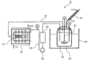
- FIG. 1 is a diagram showing an embodiment of a manufacturing apparatus used in this aspect. Needless to say, the present invention is not limited to the following embodiments.
- the manufacturing apparatus 1 keeps the temperature of the raw material constant by bringing the raw material into contact with the pulverizer (mechanical energy providing means) 10 that synthesizes the ion conductive material by reacting the raw material while pulverizing the raw material in the solvent.
- Temperature holding tank (contacting means) 20 In the present embodiment, the temperature holding tank 20 includes a container 22 and a stirring blade 24. The stirring blade 24 is driven by a motor (M).
- the pulverizer 10 is provided with a heater 30 (first temperature stabilizing means) through which hot water can be passed around the pulverizer 10 in order to keep the interior of the pulverizer 10 at 20 ° C. or higher and 80 ° C. or lower.
- the temperature holding tank 20 is in an oil bath 40 (second temperature stabilizing means) in order to keep the temperature holding tank 20 at 60 ° C. or more and 300 ° C. or less.
- the oil bath 40 heats the raw material and solvent in the container 22 to a predetermined temperature.
- the temperature holding tank 20 is provided with a cooling pipe 26 for cooling and liquefying the vaporized solvent.
- the pulverizer 10 and the temperature holding tank 20 are connected by a first connecting pipe 50 (connecting means) and a second connecting pipe 52 (connecting means).
- the first connecting pipe 50 moves the raw material and solvent in the pulverizer 10 to the temperature holding tank 20, and the second connecting portion 52 moves the raw material and solvent in the temperature holding tank 20 into the pulverizer 10.
- a pump 54 (for example, a diaphragm pump) (circulation means) is provided in the second connection pipe 52 in order to circulate the raw materials and the like through the connection pipes 50 and 52.
- the solvent and the raw material are supplied to the pulverizer 10 and the temperature holding tank 20, respectively.
- the raw material includes at least a first sulfide and a second sulfide.
- Hot water (HW) enters and exits the heater 30 (RHW). While maintaining the temperature in the pulverizer 10 at 20 ° C. or higher and 80 ° C. or lower by the heater 30, the raw materials are reacted while being pulverized in a solvent to synthesize an ion conductive material. While maintaining the temperature in the temperature holding tank 20 at 60 ° C. or more and 300 ° C.
- the raw materials are reacted in a solvent to synthesize an ion conductive substance.
- the temperature in the temperature holding tank 20 is measured with a thermometer (Th).
- the stirring blade 24 is rotated by the motor (M) to stir the reaction system so that the slurry composed of the raw material and the solvent does not precipitate.
- Cooling water (CW) enters and exits the cooling pipe 26 (RCW).
- the cooling pipe 26 cools and liquefies the vaporized solvent in the container 22 and returns it to the container 22.
- thermometer provided in the second connecting pipe 52 in front of the pulverizer 10.
- the pulverizer 10 may be any pulverizer as long as it can produce an ion conductive material by pulverizing and mixing the first sulfide and the second sulfide.
- a rotary mill rolling mill
- rocking mill rocking mill
- vibration mill and a bead mill
- a bead mill is preferable in that the raw material can be finely pulverized. The finer the raw material, the higher the reactivity, and an ion conductive substance can be produced in a short time.
- the ball is preferably made of zirconium, reinforced alumina, or alumina in order to prevent contamination of the ion conductive material due to wear of the ball and the container.
- the pulverization temperature in the pulverizer is 20 ° C. or higher and 80 ° C. or lower, preferably 20 ° C. or higher and 60 ° C. or lower.
- the processing temperature in the pulverizer is less than 20 ° C., the effect of shortening the reaction time required for production is small, and when it exceeds 80 ° C., the strength of zirconia, reinforced alumina, and alumina, which are the materials of containers and balls, is significantly reduced. For this reason, there is a possibility that the container and ball are worn and deteriorated, and foreign substances are mixed into the ion conductive material.
- the temperature holding tank 20 is not particularly limited as long as it has heat transfer properties so that the temperature of the contents can be held in a predetermined temperature range by applying heat from the outside.
- the temperature holding tank has a container, mixing means such as a stirrer, and cooling means.
- the mixing means mixes the slurry composed of the raw material and the solvent in the container so that the slurry does not precipitate.
- the cooling means cools the evaporated solvent and returns it to the container.
- the container 22 is preferably made of metal or glass. When reacting at a reaction temperature equal to or higher than the boiling point of the solvent, it is preferable to use a pressure resistant container.
- the reaction temperature in the container 22 is 25 ° C. or more and 300 ° C. or less. Preferably they are 40 degreeC or more and 250 degrees C or less, More preferably, they are 60 degreeC or more and 300 degrees C or less. Below 60 ° C., the vitrification reaction takes time and the production efficiency is not sufficient. If it exceeds 300 ° C., undesirable crystals may be precipitated.
- the reaction is preferably carried out at a high temperature since the region where the temperature is high is fast, but mechanical problems such as wear occur when the pulverizer 10 is heated to a temperature exceeding 80 ° C. Accordingly, it is necessary to set the temperature holding tank 20 to a high reaction temperature and to keep the pulverizer 10 at a relatively low temperature.
- the ratio of the capacity of the temperature holding tank 20 and the capacity of the pulverizer 10 may be arbitrary, but the capacity of the normal temperature holding tank 20 is about 1 to 100 times the capacity of the pulverizer 10.
- FIG. 2 is a diagram showing another embodiment of the manufacturing apparatus used in this aspect.
- the manufacturing apparatus 2 is the same as the manufacturing apparatus 1 described above except that a heat exchanger 60 (heat exchange means) is provided in the second connecting pipe 52.
- the same members as those of the manufacturing apparatus 1 are denoted by the same reference numerals and description thereof is omitted.
- the heat exchanger 60 cools the high-temperature raw material and solvent sent out from the temperature holding tank 20 and sends them to the pulverizer 10. For example, when the reaction is carried out at a temperature exceeding 80 ° C. in the temperature holding tank 20, the temperature of the raw material or the like is cooled to 80 ° C. or less and sent to the pulverizer 10.
- the charged amount of the second sulfide during the reaction should be 30 mol% or more and 95 mol% or less with respect to the total of the second sulfide and the first sulfide. Furthermore, it is preferable to set it as 40 to 85 mol%, and it is preferable to set it as 50 to 80 mol% especially. More particularly, it is preferably 50 mol% or more and 75 mol% or less.
- the mixing ratio (molar ratio) of the halogen compound to the total molar amount of the first and second sulfides is not particularly limited, but is preferably 50:50 to 99: 1, more preferably 55:45 to 98: 2, particularly preferably 60:40 to 97: 3.
- the amount of the solvent is preferably such that the first sulfide and the second sulfide, which are raw materials, become a solution or slurry by the addition of the solvent.
- the amount of raw material (total amount) added to 1 kg of solvent is about 0.03 kg to 1 kg.
- they are 0.05 kg or more and 0.5 kg or less, Most preferably, they are 0.1 kg or more and 0.3 kg or less.
- the ion conductive substance is obtained by drying the reaction product and removing the solvent.
- the above raw material is reacted with a solvent added.
- the granulation effect at the time of a process can be suppressed and a synthesis reaction can be accelerated
- a sulfide of a metal element belonging to Group I or Group II of the periodic table having a particle size of 1 ⁇ m or more (for example, a particle size of 1 ⁇ m to 20 ⁇ m) is used. Even if it is, it can be made to react easily.
- the particle diameter here is an average particle diameter measured by a laser diffraction / scattering particle size distribution analyzer.
- the 4th aspect (4th manufacturing method) of the manufacturing method of this invention is 1 or more types selected from phosphorus sulfide, germanium sulfide, silicon sulfide, and boron sulfide. And a metal compound sulfide belonging to Group I or Group II of the periodic table and the halogen compound represented by the formula (1) described in the first embodiment are mechanically milled in a solvent.
- the raw materials (first sulfide, second sulfide, halogen compound) and solvent used in this embodiment are the same as those in the first production method described above.
- the use ratio of the raw materials and the solvent is the same as in the third production method described above.
- the mechanical milling treatment step various types of pulverization methods exemplified in the second production method described above can be used.
- the temperature of the mechanical milling process is the same as the temperature of the mechanical energy supply means (pulverizer 10) of the third manufacturing method described above.
- the rotation speed and rotation time of the mechanical milling treatment are not particularly limited, but the higher the rotation speed, the higher the glassy electrolyte generation rate, and the longer the rotation time, the higher the conversion rate of the raw material into the glassy electrolyte.
- the rotational speed may be 250 rpm / min to 300 rpm / min, and the treatment may be 5 minutes to 50 hours.
- the processing time indicates the time during which the raw material and the glassy electrolyte remain in the planetary ball mill.
- the present invention circulates the raw material and the glassy electrolyte through the planetary ball mill and the temperature holding tank, but is the total time that the raw material and the glassy electrolyte remain in the planetary ball mill from the start to the end of the reaction. .
- the contact means illustrated by the 3rd manufacturing method mentioned above can be used.
- the temperature in the contact step is the same as the reaction temperature in the contact means (container 22) of the third production method described above.
- the time for the contacting step is preferably from 5 minutes to 200 hours.
- the time of the said contact process shows the time when the raw material and the glassy electrolyte remain in the temperature holding tank.
- the raw material and the glassy electrolyte circulate through the planetary ball mill and the temperature holding tank, but the total time during which the raw material and the glassy electrolyte remain in the temperature holding tank from the start to the end of the reaction.
- the mechanical milling process and the contact process described above are repeated alternately.
- the number of repetitions is preferably 2 or more and 100 or less. More preferably, the number of repetitions is 5 or more and 100 or less, and further preferably 10 or more and 100 or less.
- the treatment in other aspects may be performed continuously.
- the reaction may be completed by continuously treating in the third embodiment.
- the treatment may be completed in a manner to complete the reaction.
- processing in the second aspect processing in the third aspect may be performed, processing in the second aspect after processing in the second aspect, You may perform a process in a 4th aspect.
- the ion conductive material of the present invention can be obtained by any one of the first to fourth production methods described above.
- the ion conductive material means a material that conducts ions of metal elements belonging to Group I or Group II of the periodic table.
- the ionic conductivity is preferably 1 ⁇ 10 ⁇ 5 S / cm or more, more preferably 1 ⁇ 10 ⁇ 4 S / cm or more, and further preferably 2 ⁇ 10 ⁇ 4 S / cm or more. Most preferably, it is 3 ⁇ 10 ⁇ 4 S / cm or more.
- the upper limit is not particularly limited, but is usually 1 ⁇ 10 ⁇ 2 S / cm or less or 5 ⁇ 10 ⁇ 3 S / cm or less.
- the ionic conductivity is a value measured by AC impedance measurement. Details will be described in Examples.
- the ionic conductivity can be increased by crystallization of the ion conductive material.
- the method for producing a crystallized ion conductive material of the present invention includes sulfur (S), a metal element belonging to Group I or Group II of the periodic table, phosphorus (P), germanium (Ge), silicon (Si). Boron (B), Aluminum (Al), Arsenic (As), Selenium (Se), Tin (Sn), Antimony (Sb), Tellurium (Te), Lead (Pb) and Bismuth (Bi) Ion conductive glass containing one or more selected elements and a halogen element selected from fluorine (F), chlorine (Cl), bromine (Br) and iodine (I) is 80 ° C. or higher and 400 ° C. or lower. The process of heating at the temperature of this.
- the ion conductive glass may be an ion conductive material manufactured by any one of the first manufacturing method, the second manufacturing method, the third manufacturing method, and the fourth manufacturing method.
- the raw material may be manufactured by mechanical milling treatment, or may be manufactured by heating to a temperature at which the raw material is dissolved and reacting.
- a raw material it is the same as that of the 1st manufacturing method mentioned above.
- the heating temperature of the ion conductive glass is 80 ° C. or higher and 400 ° C. or lower, preferably 170 ° C. or higher and 380 ° C. or lower, and more preferably 180 ° C. or higher and 360 ° C. or lower. If it is lower than 150 ° C., a crystallized glass having a high degree of crystallinity may be difficult to obtain. If it is higher than 400 ° C., a crystallized glass having a low crystallinity may be produced. When there are two crystallization peaks when performing differential scanning calorimetry (DSC) measurement, etc., the temperature range is higher than the temperature of the lower first peak and lower than the temperature of the higher second peak. It is preferable to heat-treat with.
- DSC differential scanning calorimetry
- the ion conductive glass is preferably heated at a dew point of ⁇ 40 ° C. or lower, more preferably at a dew point of ⁇ 60 ° C. or lower.
- the pressure at the time of heating may be a normal pressure or a reduced pressure.
- the atmosphere may be air or an inert gas atmosphere.
- the heating time is preferably from 0.1 hours to 24 hours, more preferably from 0.5 hours to 12 hours.
- the crystallized ion conductive material of the present invention is obtained.
- all of the crystallized ion conductive material may be crystallized, or a part thereof may be crystallized and the other part may be amorphous.
- a crystal body crystallized by the above crystallization method is considered to have higher ionic conductivity than an amorphous body.
- the crystallinity of the crystallized ion conductive material is preferably 50% or more, more preferably 70% or more. If the crystallization is 50% or more, the effect of improving the ionic conductivity by crystallization becomes larger.
- ion conductive material of the present invention include sulfur (S), a metal element belonging to Group I or Group II of the periodic table, phosphorus (P), germanium (Ge), silicon (Si), Selected from the group consisting of boron (B), aluminum (Al), arsenic (As), selenium (Se), tin (Sn), antimony (Sb), tellurium (Te), lead (Pb) and bismuth (Bi)
- S Sulfur
- metal elements belonging to Group I or Group II of the periodic table phosphorus (P), germanium (Ge), silicon (Si), boron (B), aluminum (Al), arsenic ( One or more elements selected from the group consisting of As), selenium (Se), tin (Sn), antimony (Sb), tellurium (Te), lead (Pb) and bismuth (Bi), and fluorine (F)
- An ion conductive material containing a halogen element selected from chlorine (Cl), bromine (Br) and iodine (I) is produced by the first to fourth aspects of the production method of the present invention described above. Examples thereof include an ion conductive substance (glass) and an ion conductive substance obtained by crystallizing the same.
- the ion conductivity of the ion conductive material of this embodiment is preferably 1 ⁇ 10 ⁇ 5 S / cm or more, more preferably 1 ⁇ 10 ⁇ 4 S / cm or more, and further preferably 2 ⁇ 10 ⁇ 4 S / cm or more, and most preferably 3 ⁇ 10 ⁇ 4 S / cm or more.
- the ion conductive material of this embodiment is preferably crystallized, and may be all crystallized, partly crystallized, and other part amorphous.
- a crystal may have higher ionic conductivity than glass (amorphous), and in this case, it is preferably crystallized.
- the crystallinity is preferably 50% or more, more preferably 70% or more. If the crystallization is 50% or more, the effect of improving the ionic conductivity by crystallization becomes larger.
- the ion conductive material of this aspect can be manufactured by the manufacturing method of the present invention and the crystallization method of the ion conductive material described above, for example.
- the crystallization method is not particularly limited.
- the ion conductive substance and the crystallized ion conductive substance of the present invention can be used as a battery material.
- the first aspect of the battery of the present invention includes at least one of the crystallized ion conductive material and the ion conductive material of the present invention.
- the crystallized ion conductive material and the ion conductive material may be included in the electrolyte layer of the battery, may be included in the electrode layer, or may be included in both the electrolyte layer and the electrode layer. .
- the battery according to another aspect of the present invention is manufactured using at least one of the crystallized ion conductive material and the ion conductive material of the present invention.
- the crystallized ion conductive material and the ion conductive material may be used for the electrolyte layer of the battery, may be used for the electrode layer, or may be used for both the electrolyte layer and the electrode layer.
- constituent members of the battery of the present invention for example, electrode active material, conductive additive, current collector, etc.
- known members can be used, and those invented in the future are also applicable.
- a method for manufacturing the battery a known manufacturing method can be applied, and a manufacturing method invented in the future may be used.
- the solid was dispersed and stirred in toluene, and there was no moisture separated from toluene. Thereafter, the hydrogen sulfide was switched to nitrogen and circulated at 300 ml / min for 1 hour.
- the solid content was filtered and dried to obtain white powder of lithium sulfide.
- the average particle size was 450 ⁇ m (slurry solution).
- Production Example 2 [Atomization process] 26 g of lithium sulfide obtained in Production Example 1 was weighed into a Schlenk bottle in a glove box. Under a nitrogen atmosphere, 500 ml of dehydrated toluene (Wako Pure Chemical Industries, Ltd.) and 250 ml of dehydrated ethanol (Wako Pure Chemical Industries, Ltd.) were added in this order, and the mixture was stirred with a stirrer at room temperature for 24 hours. After the reforming treatment, the bath temperature was raised to 120 ° C., and hydrogen sulfide gas was circulated at 200 ml / min for 90 minutes to carry out the treatment. After the hydrogen sulfide gas treatment, the solvent was distilled off under a nitrogen stream at room temperature, and further dried under vacuum at room temperature for 2 hours to recover atomized lithium sulfide.
- the atomized lithium sulfide was evaluated in the same manner as in Production Example 1.
- the lithium sulfide had a purity of 97.2%, an amount of lithium hydroxide of 0.3%, an average particle size of 9.1 ⁇ m (undried slurry solution), a specific surface area of 43.2 m 2 / g, and a pore volume of 0.68 ml / g. It was. Purity and lithium hydroxide content were each determined by titration. The total analysis value does not become 100% because it contains lithium carbonate and other ionic salts and residual solvent.
- Example 1 Lithium sulfide (LiS 2 ) produced in Production Example 1 was pulverized by a jet mill (Aisin Nano Technologies Co., Ltd.), and the average particle size was 0.3 ⁇ m. Its lithium sulfide 1.0 g (64 mol%), pentasulfide wheel (P 2 S 5) (Aldrich) 1.61 g (21 mol%) and lithium bromide (LiBr) (Aldrich) 0.42 g (15 Mol%) was placed in a flask equipped with a stirrer substituted with nitrogen, 50 ml of xylene (Wako Pure Chemical Industries, Ltd.) having a water content of 10 ppm was added, and contacted at 140 ° C. for 24 hours.
- solid component was separated by filtration and vacuum dried at 120 ° C. for 40 minutes to obtain an ion conductive substance (solid electrolyte).
- the recovery rate of the solid electrolyte was 95%. There were no deposits on the flasks and stirrers used.
- the ionic conductivity of this solid electrolyte was 4.6 ⁇ 10 ⁇ 4 S / cm.
- the particle size of lithium sulfide was measured using a laser diffraction / scattering particle size distribution analyzer LMS-30 (Seishin Enterprise Co., Ltd.). Moreover, the ionic conductivity was measured by the following method.
- the solid electrolyte was filled into a tablet molding machine, and a molded body was obtained by applying a pressure of 4 to 6 MPa. Furthermore, a mixture obtained by mixing carbon and a solid electrolyte at a weight ratio of 1: 1 as an electrode is placed on both sides of the molded body, and pressure is applied again with a tablet molding machine, thereby forming a molded body for conductivity measurement (diameter of about 10 mm). , About 1 mm thick). The ion conductivity of this molded body was measured by AC impedance measurement. The conductivity value was a value at 25 ° C.
- the obtained ion conductive material was sealed in a SUS tube in an Ar atmosphere in a glove box and heat-treated at 230 ° C. for 2 hours to obtain a crystallized solid electrolyte.
- the ionic conductivity of the solid electrolyte after the heat treatment was 1.3 ⁇ 10 ⁇ 3 S / cm.
- Example 2 Li 2 S and P 2 S 5 (Aldrich) and LiBr (Aldrich) of Production Example 1 were used as starting materials. Li 2 S 0.337 g (64 mol%), P 2 S 5 0.532 g (21 mol%) and LiBr 0.141 g (15 mol%) were placed in a 45 ml alumina container containing 10 10 mm ⁇ alumina balls, and further dehydrated. 3 ml of toluene (Wako Pure Chemical Industries, Ltd.) was added and sealed. The above weighing, addition and sealing operations were all carried out in a glove box and under a nitrogen atmosphere, and all the instruments used were those which had been previously removed with a dryer. The water content in dehydrated toluene was 8.4 ppm as measured by the Karl Fischer method.
- the sealed alumina container was mechanically milled at 370 rpm for 20 hours at room temperature using a planetary ball mill (P-7, manufactured by Fritsch) to obtain a white-yellow powder slurry (cream).
- P-7 planetary ball mill
- the obtained slurry was filtered and air-dried, and then dried with a tube heater at 160 ° C. for 2 hours to obtain an ion conductive substance (solid electrolyte) as a powder.
- the recovery rate at this time was 95%, and no deposit was observed in the container.
- the ionic conductivity of this glass ion conductive material was 4.2 ⁇ 10 ⁇ 4 S / cm.
- the obtained solid electrolyte powder is put in a SUS tube in an Ar atmosphere in a glove box and sealed, and heat-treated at 230 ° C. for 2 hours to obtain a crystallized ion conductive material (solid electrolyte glass ceramic). It was.
- the ionic conductivity of this electrolyte glass ceramic was 1.2 ⁇ 10 ⁇ 3 S / cm.
- Example 3 The apparatus shown in FIG. 1 was used. As a stirrer, 444 g of 0.5 mm ⁇ zirconia balls were charged using a star mill mini-zea (0.15 L) (bead mill) manufactured by Ashizawa Finetech. A 1.5 L glass reactor with a stirrer was used as a temperature holding tank. The above weighing, addition and sealing operations were all carried out in a glove box and under a nitrogen atmosphere, and all the instruments used were those which had been previously removed with a dryer. The water content in dehydrated toluene was 8.4 ppm as measured by the Karl Fischer method.
- Lithium sulfide of Preparation 1 33.7 g (64 mol%), P 2 S 5 (Aldrich) 53.2 g (21 mol%), the LiBr (Aldrich) 14.1 g (15 mol%), dehydrated toluene ( Wako Pure Chemical Industries, Ltd.) 1248 ml (moisture content 8.4 ppm) was added to the temperature holding tank and mill.
- the contents were circulated between the temperature holding tank and the mill at a flow rate of 480 ml / min by a pump, and the temperature holding tank was heated to 70-80 ° C.
- the mill body was operated under conditions of a peripheral speed of 12 m / s by passing warm water by external circulation so that the liquid temperature could be maintained at 70 ° C.
- the slurry was collected every 2 hours and dried at 150 ° C. to obtain a white-yellow powder slurry (cream).
- the obtained slurry was filtered and air-dried and then dried with a tube heater at 160 ° C. for 2 hours to obtain a solid electrolyte as a powder.
- the recovery rate at this time was 95%, and no deposits were observed in the reactor.
- Example 4 As raw materials, 30.9 g (64 mol%) of lithium sulfide of Production Example 1, 49.4 g (21 mol%) of P 2 S 5 (Aldrich), lithium iodide (LiI) (Wako Pure Chemical Industries, Ltd.) ) was used in the same manner as in Example 3 except that 20.0 g (15 mol%) was used. The recovery rate at this time was 95%, and no deposits were observed in the reactor.
- the obtained glass had an ionic conductivity of 5.4 ⁇ 10 ⁇ 4 S / cm. This glass was sealed in a SUS tube under an Ar atmosphere, and heat-treated at 210 ° C. for 2 hours to obtain a solid electrolyte glass ceramic. The ionic conductivity of the electrolyte glass ceramic was 2.1 ⁇ 10 ⁇ 3 S / cm.
- Example 5 As raw materials, 39.7 g (76 mol%) of lithium sulfide of Production Example 1, 46.7 g (19 mol%) of P 2 S 5 (Aldrich), phosphorus tribromide (PBr 3 ) (Tokyo Chemical Industry) was used in the same manner as in Example 3 except that 14.8 g (5 mol%) was used. The recovery rate at this time was 95%, and no deposits were observed in the reactor.
- the ionic conductivity of the obtained glass was 2.0 ⁇ 10 ⁇ 4 S / cm. This glass was sealed in an SUS tube under an Ar atmosphere, and heat-treated at 240 ° C. for 2 hours to obtain a solid electrolyte glass ceramic. The ionic conductivity of the electrolyte glass ceramic was 7.0 ⁇ 10 ⁇ 4 S / cm.
- Comparative Example 1 The compound was synthesized in the same manner as in Example 2 except that no solvent was used. Specifically, Li 2 S and P 2 S 5 (Aldrich) and LiBr (Aldrich) of Production Example 1 were used as starting materials. Li 2 S 0.337 g (64 mol%), P 2 S 5 0.532 g (21 mol%) and LiBr 0.141 g (14 mol%) were placed in a 45 ml alumina container containing 10 10 mm ⁇ alumina balls. The above weighing, addition and sealing operations were all carried out in the glove box, and all the instruments used were water removed beforehand by a dryer.
- the sealed alumina container was mechanically milled at 370 rpm for 20 hours at room temperature using a planetary ball mill (P-7, manufactured by Fritsch). After completion of the mechanical milling treatment, white yellow-fixed matter adhered to the vessel wall, lid, and ball of the alumina container, and no powder was produced. The fixed matter was crushed with a hammer or the like, peeled off from the vessel wall, the lid and the ball, and further pulverized with a mortar to obtain a white yellow powder. In addition, it took a very long time to remove the fixed matter from the vessel wall and the like, and it took a very long time to grind it in a mortar.
- P-7 planetary ball mill
- the ionic conductivity of this glass solid electrolyte was 6.5 ⁇ 10 ⁇ 4 S / cm.
- the ionic conductivity of the crystallized solid electrolyte after heat treatment at 230 ° C. for 2 hours in an argon atmosphere was 1.7 ⁇ 10 ⁇ 3 S / cm.
- Comparative Example 2 As raw materials, 0.309 g (64 mol%) of lithium sulfide of Production Example 1, 0.494 g (21 mol%) of P 2 S 5 (Aldrich), and 0.14 of lithium iodide (Wako Pure Chemical Industries, Ltd.) were used. An ion conductive material was produced in the same manner as in Comparative Example 1 except that 20 g (15 mol%) was used. As in Comparative Example 1, deposits were found on the wall, lid, and balls of the alumina container, and the recovery rate was 62%. The obtained glass solid electrolyte had an ionic conductivity of 5.3 ⁇ 10 ⁇ 4 S / cm. The ionic conductivity of the crystallized solid electrolyte after heat treatment at 210 ° C. for 2 hours in an argon atmosphere was 1.7 ⁇ 10 ⁇ 3 S / cm.
- Example 6 A 0.5 L autoclave with a stirring blade was replaced with nitrogen, and 10.0 g (64 mol%) of lithium sulfide prepared in Production Example 1, 15.8 g (21 mol%) of P 2 S 5 (Aldrich), LiBr ( (Aldrich) 4.18 g (15 mol%) and 300 ml of toluene (Wako Pure Chemical Industries, Ltd.) having a water content of 8.4 ppm were charged and reacted at 150 ° C. for 72 hours. This slurry solution was vacuum dried to obtain a solid electrolyte glass. Compared to Example 1, a peak derived from the raw material was observed relatively strongly in the X-ray diffraction pattern.
- the recovery rate at this time was 95%, and no remarkable adhesion was observed on the autoclave.
- the obtained solid electrolyte glass was in the form of powder, and the ionic conductivity was 3.2 ⁇ 10 ⁇ 4 S / cm.
- This solid electrolyte glass was put in a SUS tube in an Ar atmosphere glove box and sealed, and heat treatment was performed at 210 ° C. for 2 hours to obtain a solid electrolyte glass ceramic.
- the ionic conductivity of the obtained solid electrolyte glass ceramic was 4.5 ⁇ 10 ⁇ 4 S / cm.
- Example 7 A 0.5 L autoclave with a stirring blade was replaced with nitrogen, and 10.0 g (64 mol%) of finely divided lithium sulfide prepared in Production Example 2, 15.8 g (21 mol%) of P 2 S 5 (Aldrich), 4.18 g (15 mol%) of LiBr (Aldrich) and 300 ml of toluene (Wako Pure Chemical Industries, Ltd.) having a water content of 8.4 ppm were charged and contact-reacted at 150 ° C. for 72 hours. This slurry solution was vacuum dried to obtain a solid electrolyte glass. Compared with Example 1, a peak derived from the raw material was observed relatively strongly in the X-ray diffraction pattern, but was weaker than Example 6.
- the recovery rate at this time was 95%, and no remarkable adhesion was observed on the autoclave.
- the obtained solid electrolyte glass was in the form of powder and the ionic conductivity was 3.7 ⁇ 10 ⁇ 4 S / cm.
- This solid electrolyte glass was put in a SUS tube in an Ar atmosphere glove box and sealed, and heat treatment was performed at 210 ° C. for 2 hours to obtain a solid electrolyte glass ceramic.
- the obtained solid electrolyte glass ceramic had an ionic conductivity of 6.3 ⁇ 10 ⁇ 4 S / cm.
- Example 8 A 0.5 L autoclave with a stirring blade was replaced with nitrogen, and 10.0 g (64 mol%) of finely divided lithium sulfide prepared in Production Example 2, 15.8 g (21 mol%) of P 2 S 5 (Aldrich), 4.18 g (15 mol%) of LiBr (Aldrich) and 300 ml of toluene (Wako Pure Chemical Industries, Ltd.) having a water content of 8.4 ppm were charged and contact-reacted at 150 ° C. for 72 hours. This reaction was repeated three times to obtain a total of 900 ml of slurry solution.
- This solid electrolyte glass was sealed in a SUS tube in an Ar atmosphere glove box, and heat-treated at 210 ° C. for 2 hours to obtain an electrolyte glass ceramic.
- the obtained solid electrolyte glass ceramic had an ionic conductivity of 1.5 ⁇ 10 ⁇ 3 S / cm.
- Example 9 A 0.5 L autoclave with a stirring blade was replaced with nitrogen, and 11.7 g of finely divided lithium sulfide prepared in Production Example 2, 18.3 g of P 2 S 5 (Aldrich) and toluene with a water content of 8.4 ppm (sum) (Kogakuyaku Kogyo Co., Ltd.) was charged with 300 ml and reacted at 150 ° C. for 72 hours. This reaction was repeated three times to obtain a total of 900 ml of slurry solution.
- the obtained solid electrolyte glass was powdery and had an ionic conductivity of 5.3 ⁇ 10 ⁇ 4 S / cm.
- This solid electrolyte glass was sealed in a SUS tube in an Ar atmosphere glove box, and heat-treated at 210 ° C. for 2 hours to obtain an electrolyte glass ceramic.
- the ionic conductivity of the obtained solid electrolyte glass ceramic was 2.1 ⁇ 10 ⁇ 3 S / cm.
- the production method of the present invention is suitable for production of an ion conductive material such as sulfide glass.
- the ion conductive substance and crystalline ion conductive substance of this invention can be used as raw materials, such as a sodium secondary battery.
Landscapes
- Chemical & Material Sciences (AREA)
- Manufacturing & Machinery (AREA)
- General Physics & Mathematics (AREA)
- Condensed Matter Physics & Semiconductors (AREA)
- Inorganic Chemistry (AREA)
- Engineering & Computer Science (AREA)
- Physics & Mathematics (AREA)
- Chemical Kinetics & Catalysis (AREA)
- Electrochemistry (AREA)
- General Chemical & Material Sciences (AREA)
- Secondary Cells (AREA)
- Glass Compositions (AREA)
- Conductive Materials (AREA)
Abstract
Priority Applications (4)
| Application Number | Priority Date | Filing Date | Title |
|---|---|---|---|
| JP2014524616A JP6145091B2 (ja) | 2012-07-12 | 2013-06-12 | イオン伝導性物質の製造方法、イオン伝導性物質、結晶化イオン伝導性物質及び電池 |
| EP13816812.5A EP2874158B1 (fr) | 2012-07-12 | 2013-06-12 | Procédé de fabrication de substance conductrice des ions, substance conductrice des ions, substance cristallisée conductrice des ions, et cellule |
| US14/414,255 US20150171464A1 (en) | 2012-07-12 | 2013-06-12 | Method for producing ion-conductive substance, ion-conductive substance, crystallized ion-conductive substance, and cell |
| CN201380037045.XA CN104412338A (zh) | 2012-07-12 | 2013-06-12 | 离子传导性物质的制造方法、离子传导性物质、结晶离子传导性物质及电池 |
Applications Claiming Priority (2)
| Application Number | Priority Date | Filing Date | Title |
|---|---|---|---|
| JP2012-156278 | 2012-07-12 | ||
| JP2012156278 | 2012-07-12 |
Publications (1)
| Publication Number | Publication Date |
|---|---|
| WO2014010169A1 true WO2014010169A1 (fr) | 2014-01-16 |
Family
ID=49915654
Family Applications (1)
| Application Number | Title | Priority Date | Filing Date |
|---|---|---|---|
| PCT/JP2013/003696 Ceased WO2014010169A1 (fr) | 2012-07-12 | 2013-06-12 | Procédé de fabrication de substance conductrice des ions, substance conductrice des ions, substance cristallisée conductrice des ions, et cellule |
Country Status (6)
| Country | Link |
|---|---|
| US (1) | US20150171464A1 (fr) |
| EP (1) | EP2874158B1 (fr) |
| JP (1) | JP6145091B2 (fr) |
| CN (1) | CN104412338A (fr) |
| TW (1) | TW201414045A (fr) |
| WO (1) | WO2014010169A1 (fr) |
Cited By (13)
| Publication number | Priority date | Publication date | Assignee | Title |
|---|---|---|---|---|
| CN104810547A (zh) * | 2014-01-24 | 2015-07-29 | 丰田自动车株式会社 | 硫化物固体电解质的制造方法 |
| JP2016066405A (ja) * | 2014-09-22 | 2016-04-28 | 公立大学法人大阪府立大学 | 全固体二次電池用固体電解質、その製造方法及びそれを含む全固体二次電池 |
| JP2017112100A (ja) * | 2015-12-15 | 2017-06-22 | 現代自動車株式会社Hyundai Motor Company | 二次電池用硫化物系結晶化ガラスの製造方法 |
| JP2018080100A (ja) * | 2016-11-16 | 2018-05-24 | 現代自動車株式会社Hyundai Motor Company | 湿式工程による硫化物系固体電解質の製造方法 |
| US20180155198A1 (en) * | 2015-06-17 | 2018-06-07 | Idemitsu Kosan Co., Ltd. | Solid electrolyte production method |
| CN109065834A (zh) * | 2018-07-12 | 2018-12-21 | 合肥国轩高科动力能源有限公司 | 一种锂离子用无机钙钛矿衍生相作负极材料的制备方法 |
| JP2020095953A (ja) * | 2018-12-05 | 2020-06-18 | 出光興産株式会社 | アルジロダイト型結晶構造を有する固体電解質の製造方法 |
| US11129714B2 (en) | 2012-03-01 | 2021-09-28 | Twelve, Inc. | Hydraulic delivery systems for prosthetic heart valve devices and associated methods |
| JP2021163758A (ja) * | 2020-03-31 | 2021-10-11 | 出光興産株式会社 | 固体電解質の製造方法 |
| US11183708B2 (en) | 2015-04-17 | 2021-11-23 | Idemitsu Kosan Co., Ltd. | Method for producing sulfide solid electrolyte and sulfur-based material |
| US11559398B2 (en) | 2017-06-02 | 2023-01-24 | Twelve, Inc. | Delivery systems with telescoping capsules for deploying prosthetic heart valve devices and associated methods |
| JP2024117424A (ja) * | 2023-02-17 | 2024-08-29 | エルジー エナジー ソリューション リミテッド | 硫化物系固体電解質、硫化物系固体電解質の製造方法、及び硫化物系固体電解質を含む全固体電池 |
| US12201523B2 (en) | 2017-04-18 | 2025-01-21 | Twelve, Inc. | Hydraulic systems for delivering prosthetic heart valve devices and associated methods |
Families Citing this family (11)
| Publication number | Priority date | Publication date | Assignee | Title |
|---|---|---|---|---|
| EP3312847A4 (fr) * | 2015-06-17 | 2018-12-26 | Idemitsu Kosan Co.,Ltd. | Procédé de production d'électrolyte solide |
| KR102417506B1 (ko) * | 2016-11-16 | 2022-07-05 | 현대자동차주식회사 | 단일원소로부터 유래된 고체전해질 및 이의 제조방법 |
| CN114976221A (zh) | 2017-11-14 | 2022-08-30 | 出光兴产株式会社 | 含金属元素的硫化物类固体电解质及其制造方法 |
| CN109935900B (zh) * | 2017-12-19 | 2021-10-19 | 成都大超科技有限公司 | 固态电解质及其锂电池、锂电池电芯及其制备方法 |
| CN109935903B (zh) * | 2017-12-19 | 2021-05-14 | 成都大超科技有限公司 | 固态电解质及其锂电池电芯、锂电池 |
| CN108172898B (zh) * | 2018-01-02 | 2020-10-27 | 北京理工大学 | 复合电解质及其制备方法和全固态钠离子电池 |
| JP7125062B2 (ja) * | 2019-01-25 | 2022-08-24 | 株式会社東芝 | 判定方法及び処理方法 |
| JP6896202B1 (ja) * | 2019-11-21 | 2021-06-30 | 出光興産株式会社 | 硫化物固体電解質の製造方法 |
| CN113130978A (zh) * | 2020-01-15 | 2021-07-16 | 多氟多化工股份有限公司 | 一种无机硫化物固体电解质及其制备方法 |
| CN113644314B (zh) * | 2020-05-11 | 2022-12-30 | 中国科学技术大学 | 一种氟离子固态电解质材料及其制备方法 |
| CN112768757B (zh) * | 2021-01-18 | 2022-02-01 | 南开大学 | 空气稳定的多元稀土氧化物掺杂的锂锗磷硫固体电解质及其制备方法 |
Citations (5)
| Publication number | Priority date | Publication date | Assignee | Title |
|---|---|---|---|---|
| JPH05306117A (ja) * | 1992-05-07 | 1993-11-19 | Matsushita Electric Ind Co Ltd | 非晶質リチウムイオン伝導性固体電解質並びにその合成法 |
| JPH10321256A (ja) * | 1997-05-19 | 1998-12-04 | Matsushita Electric Ind Co Ltd | 固体電解質あるいは電極の加工方法及びリチウム電池の製造方法 |
| WO2012026561A2 (fr) | 2010-08-26 | 2012-03-01 | Toyota Jidosha Kabushiki Kaisha | Matière électrolytique solide à base de sulfure, corps de cathode et batterie au lithium à l'état solide |
| JP2012048973A (ja) * | 2010-08-26 | 2012-03-08 | Toyota Motor Corp | 硫化物固体電解質材料およびリチウム固体電池 |
| JP2012104279A (ja) * | 2010-11-08 | 2012-05-31 | Toyota Motor Corp | 硫化物固体電解質材料、リチウム固体電池、および硫化物固体電解質材料の製造方法 |
Family Cites Families (6)
| Publication number | Priority date | Publication date | Assignee | Title |
|---|---|---|---|---|
| US5085953A (en) * | 1990-09-18 | 1992-02-04 | Eveready Battery Company, Inc. | Vitreous compositions based on Li3 PO4 and LiPO3 as network formers and network modifiers |
| US20060063051A1 (en) * | 2004-09-20 | 2006-03-23 | Jang Bor Z | Metal-air battery with ion-conducting inorganic glass electrolyte |
| US8518585B2 (en) * | 2007-10-11 | 2013-08-27 | Idemitsu Kosan Co., Ltd. | Method for producing lithium ion conductive solid electrolyte |
| JP5599573B2 (ja) * | 2009-04-10 | 2014-10-01 | 出光興産株式会社 | 固体電解質粒子からなるガラス及びリチウム電池 |
| JP5287739B2 (ja) * | 2009-05-01 | 2013-09-11 | トヨタ自動車株式会社 | 固体電解質材料 |
| JP5443445B2 (ja) * | 2011-07-06 | 2014-03-19 | トヨタ自動車株式会社 | 硫化物固体電解質材料、リチウム固体電池、および、硫化物固体電解質材料の製造方法 |
-
2013
- 2013-06-12 EP EP13816812.5A patent/EP2874158B1/fr active Active
- 2013-06-12 US US14/414,255 patent/US20150171464A1/en not_active Abandoned
- 2013-06-12 WO PCT/JP2013/003696 patent/WO2014010169A1/fr not_active Ceased
- 2013-06-12 JP JP2014524616A patent/JP6145091B2/ja active Active
- 2013-06-12 CN CN201380037045.XA patent/CN104412338A/zh active Pending
- 2013-06-14 TW TW102121126A patent/TW201414045A/zh unknown
Patent Citations (5)
| Publication number | Priority date | Publication date | Assignee | Title |
|---|---|---|---|---|
| JPH05306117A (ja) * | 1992-05-07 | 1993-11-19 | Matsushita Electric Ind Co Ltd | 非晶質リチウムイオン伝導性固体電解質並びにその合成法 |
| JPH10321256A (ja) * | 1997-05-19 | 1998-12-04 | Matsushita Electric Ind Co Ltd | 固体電解質あるいは電極の加工方法及びリチウム電池の製造方法 |
| WO2012026561A2 (fr) | 2010-08-26 | 2012-03-01 | Toyota Jidosha Kabushiki Kaisha | Matière électrolytique solide à base de sulfure, corps de cathode et batterie au lithium à l'état solide |
| JP2012048973A (ja) * | 2010-08-26 | 2012-03-08 | Toyota Motor Corp | 硫化物固体電解質材料およびリチウム固体電池 |
| JP2012104279A (ja) * | 2010-11-08 | 2012-05-31 | Toyota Motor Corp | 硫化物固体電解質材料、リチウム固体電池、および硫化物固体電解質材料の製造方法 |
Cited By (19)
| Publication number | Priority date | Publication date | Assignee | Title |
|---|---|---|---|---|
| US11129714B2 (en) | 2012-03-01 | 2021-09-28 | Twelve, Inc. | Hydraulic delivery systems for prosthetic heart valve devices and associated methods |
| US12161552B2 (en) | 2012-03-01 | 2024-12-10 | Twelve, Inc. | Hydraulic delivery systems for prosthetic heart valve devices and associated methods |
| CN104810547A (zh) * | 2014-01-24 | 2015-07-29 | 丰田自动车株式会社 | 硫化物固体电解质的制造方法 |
| JP2016066405A (ja) * | 2014-09-22 | 2016-04-28 | 公立大学法人大阪府立大学 | 全固体二次電池用固体電解質、その製造方法及びそれを含む全固体二次電池 |
| US11183708B2 (en) | 2015-04-17 | 2021-11-23 | Idemitsu Kosan Co., Ltd. | Method for producing sulfide solid electrolyte and sulfur-based material |
| US20180155198A1 (en) * | 2015-06-17 | 2018-06-07 | Idemitsu Kosan Co., Ltd. | Solid electrolyte production method |
| JP2017112100A (ja) * | 2015-12-15 | 2017-06-22 | 現代自動車株式会社Hyundai Motor Company | 二次電池用硫化物系結晶化ガラスの製造方法 |
| JP2018080100A (ja) * | 2016-11-16 | 2018-05-24 | 現代自動車株式会社Hyundai Motor Company | 湿式工程による硫化物系固体電解質の製造方法 |
| US12201523B2 (en) | 2017-04-18 | 2025-01-21 | Twelve, Inc. | Hydraulic systems for delivering prosthetic heart valve devices and associated methods |
| US12329639B2 (en) | 2017-06-02 | 2025-06-17 | Twelve, Inc. | Delivery systems with telescoping capsules for deploying prosthetic heart valve devices and associated methods |
| US11559398B2 (en) | 2017-06-02 | 2023-01-24 | Twelve, Inc. | Delivery systems with telescoping capsules for deploying prosthetic heart valve devices and associated methods |
| CN109065834B (zh) * | 2018-07-12 | 2021-07-09 | 合肥国轩高科动力能源有限公司 | 一种锂离子用无机钙钛矿衍生相作负极材料的制备方法 |
| CN109065834A (zh) * | 2018-07-12 | 2018-12-21 | 合肥国轩高科动力能源有限公司 | 一种锂离子用无机钙钛矿衍生相作负极材料的制备方法 |
| JP7319900B2 (ja) | 2018-12-05 | 2023-08-02 | 出光興産株式会社 | アルジロダイト型結晶構造を有する固体電解質の製造方法 |
| JP2020095953A (ja) * | 2018-12-05 | 2020-06-18 | 出光興産株式会社 | アルジロダイト型結晶構造を有する固体電解質の製造方法 |
| JP7575981B2 (ja) | 2020-03-31 | 2024-10-30 | 出光興産株式会社 | 固体電解質の製造方法 |
| JP2021163758A (ja) * | 2020-03-31 | 2021-10-11 | 出光興産株式会社 | 固体電解質の製造方法 |
| JP2024117424A (ja) * | 2023-02-17 | 2024-08-29 | エルジー エナジー ソリューション リミテッド | 硫化物系固体電解質、硫化物系固体電解質の製造方法、及び硫化物系固体電解質を含む全固体電池 |
| JP7837913B2 (ja) | 2023-02-17 | 2026-03-31 | エルジー エナジー ソリューション リミテッド | 硫化物系固体電解質、硫化物系固体電解質の製造方法、及び硫化物系固体電解質を含む全固体電池 |
Also Published As
| Publication number | Publication date |
|---|---|
| EP2874158A1 (fr) | 2015-05-20 |
| EP2874158A4 (fr) | 2016-03-30 |
| JP6145091B2 (ja) | 2017-06-07 |
| CN104412338A (zh) | 2015-03-11 |
| TW201414045A (zh) | 2014-04-01 |
| US20150171464A1 (en) | 2015-06-18 |
| EP2874158B1 (fr) | 2018-11-07 |
| JPWO2014010169A1 (ja) | 2016-06-20 |
Similar Documents
| Publication | Publication Date | Title |
|---|---|---|
| JP6145091B2 (ja) | イオン伝導性物質の製造方法、イオン伝導性物質、結晶化イオン伝導性物質及び電池 | |
| JP6302901B2 (ja) | 固体電解質の製造方法 | |
| JP6761024B2 (ja) | 固体電解質及び固体電解質の製造方法 | |
| JP5396239B2 (ja) | 固体電解質の製造装置及び製造方法 | |
| EP3557680B1 (fr) | Méthode pour produire un électrolyte solide de type sulfure | |
| JP7319900B2 (ja) | アルジロダイト型結晶構造を有する固体電解質の製造方法 | |
| JP6186296B2 (ja) | 結晶化硫化物系固体電解質の製造方法 | |
| JP2018203569A (ja) | アルジロダイト型結晶構造を有する硫化物固体電解質の製造方法 | |
| CN108780682A (zh) | 固体电解质的制造方法 | |
| JP6063464B2 (ja) | 硫化物系ガラスと硫化物系ガラスセラミックスの製造方法 | |
| CN111788641B (zh) | 具有硫银锗矿型晶体结构的硫化物固体电解质的制造方法 | |
| JP2017188352A (ja) | 固体電解質の製造方法 | |
| JP2015002053A (ja) | 固体電解質組成物 | |
| JP6118521B2 (ja) | 硫化物系固体電解質を含む電極層、硫化物系固体電解質を含む電解質層及びそれらを用いた全固体電池 | |
| JP2015002052A (ja) | 正極合材及びそれを用いた固体リチウム電池 | |
| JP5823811B2 (ja) | イオン伝導性物質の製造方法、イオン伝導性物質、結晶化イオン伝導性物質及び電池 | |
| JP2014028717A (ja) | 固体電解質 | |
| JP2018101593A (ja) | 固体電解質の製造方法 | |
| JP6121110B2 (ja) | 固体電解質粒子及びその組成物 | |
| JP2016141574A (ja) | 固体電解質の製造方法 | |
| JP2018206611A (ja) | アルジロダイト型結晶構造を有する硫化物固体電解質の製造方法 | |
| JP2014091664A (ja) | 固体電解質ガラス粒子及びリチウムイオン電池 |
Legal Events
| Date | Code | Title | Description |
|---|---|---|---|
| 121 | Ep: the epo has been informed by wipo that ep was designated in this application |
Ref document number: 13816812 Country of ref document: EP Kind code of ref document: A1 |
|
| ENP | Entry into the national phase |
Ref document number: 2014524616 Country of ref document: JP Kind code of ref document: A |
|
| WWE | Wipo information: entry into national phase |
Ref document number: 2013816812 Country of ref document: EP |
|
| NENP | Non-entry into the national phase |
Ref country code: DE |
|
| WWE | Wipo information: entry into national phase |
Ref document number: 14414255 Country of ref document: US |