WO2014010396A1 - Unité de pile - Google Patents
Unité de pile Download PDFInfo
- Publication number
- WO2014010396A1 WO2014010396A1 PCT/JP2013/067268 JP2013067268W WO2014010396A1 WO 2014010396 A1 WO2014010396 A1 WO 2014010396A1 JP 2013067268 W JP2013067268 W JP 2013067268W WO 2014010396 A1 WO2014010396 A1 WO 2014010396A1
- Authority
- WO
- WIPO (PCT)
- Prior art keywords
- terminal
- battery
- contact
- flexible substrate
- positive electrode
- Prior art date
- Legal status (The legal status is an assumption and is not a legal conclusion. Google has not performed a legal analysis and makes no representation as to the accuracy of the status listed.)
- Ceased
Links
Images


Classifications
-
- H—ELECTRICITY
- H01—ELECTRIC ELEMENTS
- H01M—PROCESSES OR MEANS, e.g. BATTERIES, FOR THE DIRECT CONVERSION OF CHEMICAL ENERGY INTO ELECTRICAL ENERGY
- H01M10/00—Secondary cells; Manufacture thereof
- H01M10/42—Methods or arrangements for servicing or maintenance of secondary cells or secondary half-cells
- H01M10/46—Accumulators structurally combined with charging apparatus
-
- H—ELECTRICITY
- H01—ELECTRIC ELEMENTS
- H01M—PROCESSES OR MEANS, e.g. BATTERIES, FOR THE DIRECT CONVERSION OF CHEMICAL ENERGY INTO ELECTRICAL ENERGY
- H01M50/00—Constructional details or processes of manufacture of the non-active parts of electrochemical cells other than fuel cells, e.g. hybrid cells
- H01M50/10—Primary casings; Jackets or wrappings
- H01M50/102—Primary casings; Jackets or wrappings characterised by their shape or physical structure
- H01M50/109—Primary casings; Jackets or wrappings characterised by their shape or physical structure of button or coin shape
-
- H—ELECTRICITY
- H02—GENERATION; CONVERSION OR DISTRIBUTION OF ELECTRIC POWER
- H02J—ELECTRIC POWER NETWORKS; CIRCUIT ARRANGEMENTS OR SYSTEMS FOR SUPPLYING OR DISTRIBUTING ELECTRIC POWER; SYSTEMS FOR STORING ELECTRIC ENERGY
- H02J50/00—Circuit arrangements or systems for wireless supply or distribution of electric power
- H02J50/10—Circuit arrangements or systems for wireless supply or distribution of electric power using inductive coupling
-
- H—ELECTRICITY
- H02—GENERATION; CONVERSION OR DISTRIBUTION OF ELECTRIC POWER
- H02J—ELECTRIC POWER NETWORKS; CIRCUIT ARRANGEMENTS OR SYSTEMS FOR SUPPLYING OR DISTRIBUTING ELECTRIC POWER; SYSTEMS FOR STORING ELECTRIC ENERGY
- H02J7/00—Circuit arrangements for charging or discharging batteries or for supplying loads from batteries
- H02J7/70—Circuit arrangements for charging or discharging batteries or for supplying loads from batteries characterised by the mechanical construction
-
- H—ELECTRICITY
- H01—ELECTRIC ELEMENTS
- H01M—PROCESSES OR MEANS, e.g. BATTERIES, FOR THE DIRECT CONVERSION OF CHEMICAL ENERGY INTO ELECTRICAL ENERGY
- H01M10/00—Secondary cells; Manufacture thereof
- H01M10/05—Accumulators with non-aqueous electrolyte
- H01M10/052—Li-accumulators
- H01M10/0525—Rocking-chair batteries, i.e. batteries with lithium insertion or intercalation in both electrodes; Lithium-ion batteries
-
- Y—GENERAL TAGGING OF NEW TECHNOLOGICAL DEVELOPMENTS; GENERAL TAGGING OF CROSS-SECTIONAL TECHNOLOGIES SPANNING OVER SEVERAL SECTIONS OF THE IPC; TECHNICAL SUBJECTS COVERED BY FORMER USPC CROSS-REFERENCE ART COLLECTIONS [XRACs] AND DIGESTS
- Y02—TECHNOLOGIES OR APPLICATIONS FOR MITIGATION OR ADAPTATION AGAINST CLIMATE CHANGE
- Y02E—REDUCTION OF GREENHOUSE GAS [GHG] EMISSIONS, RELATED TO ENERGY GENERATION, TRANSMISSION OR DISTRIBUTION
- Y02E60/00—Enabling technologies; Technologies with a potential or indirect contribution to GHG emissions mitigation
- Y02E60/10—Energy storage using batteries
Definitions
- the present invention relates to a battery unit including a battery and a substrate.
- a battery unit including a battery and a substrate is known.
- a configuration for example, as disclosed in JP-A-2002-298804, one surface of a coin-type electric element (battery) is connected to a substrate by soldering, while the coin-type electric element is A configuration in which a lead plate connected to the other surface is soldered to a substrate is known.
- the size of the entire battery unit is increased by the amount of the connection member. Specifically, since it is necessary to route the lead plate to the outside of the battery, the size of the battery unit increases accordingly. Further, in order to fix the lead plate on the substrate, it is necessary to secure a connection area of the lead plate on the substrate. Therefore, the area of the substrate increases accordingly.
- an object of the present invention is to obtain a compact and low-cost configuration in a battery unit including a battery and a substrate.
- a battery unit includes a battery having a positive electrode terminal and a negative electrode terminal, a flexible substrate having a plurality of contact terminals that respectively contact the positive electrode terminal and the negative electrode terminal, and the flexible substrate on the battery. And a fixing member to be fixed to.
- the flexible substrate is disposed so as to cover at least a part of the battery, and is fixed by the fixing member without being bonded to the battery (first configuration).
- a flexible substrate having a plurality of contact terminals that are in electrical contact with the positive electrode terminal and the negative electrode terminal of the battery is fixed to the battery so as to cover at least a part of the battery.
- the flexible substrate is fixed by a fixing member without being bonded to the battery. This eliminates the need for adhesion or soldering for joining the battery and the substrate. Accordingly, the manufacturing cost of the battery unit can be reduced by the amount of work such as bonding or soldering.
- joining means connecting and integrating a flexible substrate and a battery includes, for example, adhesion, soldering, welding, welding, and the like.
- the flexible substrate includes a positive terminal contact surface that contacts the positive terminal, a negative terminal contact surface that contacts the negative terminal, and a first terminal contact surface that contacts the first terminal of the device. And a second terminal contact surface that contacts the second terminal of the device and a circuit component mounting surface for mounting the circuit component (second configuration).
- the flexible substrate by providing the flexible substrate with a surface that contacts the battery, a surface that contacts the terminal on the device side, and a surface that mounts circuit components, the flexible substrate can be compactly arranged with respect to the battery. Therefore, the battery unit can be made compact.
- the flexible substrate is provided on the positive electrode terminal contact surface and is in contact with the positive electrode terminal
- the negative electrode contact terminal is provided on the negative electrode terminal contact surface and is in contact with the negative electrode terminal.
- a first external terminal provided on the first terminal contact surface and in contact with the first terminal of the device
- a second external terminal provided on the second terminal contact surface and in contact with the second terminal of the device.
- an external terminal is provided.
- the first external terminal is provided at a position overlapping with one of the positive contact terminal and the negative contact terminal when the flexible substrate is fixed to the battery and the flexible substrate is viewed in the thickness direction. It has been.
- the second external terminal is provided at a position overlapping the other contact terminal of the positive electrode contact terminal and the negative electrode contact terminal when the flexible substrate is fixed to the battery and the flexible substrate is viewed in the thickness direction.
- the first contact terminal, the second contact terminal, and the battery can be brought into contact with each other more reliably by bringing the first external terminal and the second external terminal into contact with the respective terminals of the device. Therefore, the electrical connection between the flexible substrate and the battery can be ensured without bonding the flexible substrate and the battery.
- the battery is formed in a columnar shape, and one end surface functions as one of the positive electrode terminal and the negative electrode terminal, and the other end surface functions as the positive electrode terminal and the negative electrode. It functions as the other terminal of the terminal.
- the flexible substrate includes at least one of a first body portion that contacts one end surface of the battery, a second body portion that contacts the other end surface of the battery, and the first body portion and the second body portion. And a protruding tongue.
- the first external terminal is provided on the surface of the tongue opposite to the battery (fourth configuration).
- the first external terminal can be more reliably brought into contact with the first terminal of the device.
- the fixing member is disposed so as to cover the outer peripheral side of the battery and the flexible substrate.
- a slit is provided between the base end side of the tongue and the flexible substrate so that the tongue is positioned on the fixing member (fifth configuration). Thereby, it can prevent that a tongue part and a fixing member produce interference.
- the side surface of the battery also functions as the one terminal.
- the flexible substrate further includes a protruding portion that protrudes from at least one of the first main body portion and the second main body portion and contacts a side surface of the battery.
- the protruding portion is provided with the one contact terminal in contact with the one of the positive electrode contact terminal and the negative electrode contact terminal on a surface in contact with the battery (sixth configuration).
- the flexible substrate can be more reliably brought into electrical contact with one terminal of the battery. That is, even when the contact between one surface of the battery and the flexible substrate is unstable, the one terminal of the battery and the flexible substrate can be electrically connected by the above-described configuration.
- the protruding portion is provided at a position overlapping the tongue portion in a state where the flexible substrate is fixed to the battery.
- the one contact terminal provided on the protruding portion is pressed toward the battery side by the first terminal of the device that contacts the first external terminal of the tongue (seventh configuration).
- the contact terminal provided on the protruding portion can be more reliably brought into contact with the battery. Therefore, the contact terminal and the battery can be electrically connected without bonding or soldering the protruding portion provided with the contact terminal of the flexible substrate to the battery.
- the other contact terminal is pressed to the battery side by the second terminal of the device in contact with the second external terminal (eighth configuration).
- the battery unit further includes a non-contact charging coil that is electrically connected to the circuit component mounting surface.
- the battery is a secondary battery that is charged by non-contact charging.
- the non-contact charging coil is disposed on the circuit component mounting surface.
- the fixing member fixes the battery, the flexible substrate, and the coil in a stacked state (ninth configuration).
- the non-contact charging coil can be arranged compactly with respect to the battery and the flexible substrate.
- the flexible substrate is disposed so as to sandwich the battery (tenth configuration). Thereby, while being able to contact a flexible substrate more reliably with respect to a battery, a flexible substrate can be arrange
- the battery includes a bottomed cylindrical outer can and a bottomed cylindrical sealing can that covers the opening side of the outer can.
- the outer can has an opening side of the side wall fitted on the outer peripheral surface of the side wall of the sealing can and functions as one of the positive terminal and the negative terminal.
- the said sealing can functions as the other terminal of the said positive electrode terminal and the said negative electrode terminal (11th structure).
- the flexible substrate is fixed to the battery by the fixing member without joining. This eliminates the need for operations such as bonding or soldering when connecting the battery and the substrate, thereby reducing the manufacturing cost of the battery unit.
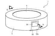
- FIG. 1 is a perspective view illustrating a schematic configuration of the battery unit according to the embodiment.
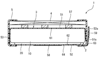
- FIG. 2 is a cross-sectional view of the cross section taken along the line II-II in FIG. 1 except for the battery.
- FIG. 3 is a cross-sectional view showing a schematic configuration of the battery.
- FIG. 4 is a diagram showing a schematic configuration of the surface of the flexible substrate on the battery side.
- FIG. 5 is a diagram showing a schematic configuration of the outer surface of the flexible substrate.
- FIG. 6 is a perspective view showing a state in which the battery is sandwiched between flexible substrates.
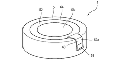
- FIG. 7 is a perspective view of the battery unit as seen from the side opposite to that in FIG.
- FIG. 8 is a cross-sectional view showing a state in which the battery unit is arranged in the device.
- FIG. 1 is a perspective view showing a schematic configuration of a battery unit 1 according to an embodiment of the present invention.
- 2 is a cross-sectional view taken along line II-II in FIG.
- the battery unit 1 includes a battery 2 configured to be chargeable / dischargeable, a flexible substrate 3 disposed so as to sandwich the battery 2, and a coil 4 for non-contact charging.
- the flexible substrate 3 is disposed so as to sandwich the battery 2 in the thickness direction with respect to the flat coin-type battery 2, and the coil 4 is laminated.
- a circuit component 57 constituting a circuit for performing charging control of the battery 2 is mounted on the flexible substrate 3 (see FIG. 2). Moreover, as shown in FIG. 2, in the battery unit 1, in the state which laminated
- the battery 2 includes a positive electrode can 10 as a bottomed cylindrical outer can, a negative electrode can 20 as a sealing can that covers the opening of the positive electrode can 10, a positive electrode can 10, and a negative electrode can 20. And an electrode body 40 accommodated in a space formed between the negative electrode can 10 and the positive electrode can 20. Therefore, by combining the positive electrode can 10 and the negative electrode can 20, the battery 2 becomes a substantially cylindrical shape having a plurality of surfaces, more precisely, a flat coin shape. In the space formed between the positive electrode can 10 and the negative electrode can 20 of the battery 2, in addition to the electrode body 40, a nonaqueous electrolytic solution (not shown) is also enclosed.
- the positive electrode can 10 is made of a metal material such as stainless steel and is formed in a bottomed cylindrical shape by press molding.
- the positive electrode can 10 includes a substantially circular bottom portion 11 (end surface) and a cylindrical peripheral wall portion 12 (side surface) formed continuously with the bottom portion 11 on the outer periphery thereof.
- the peripheral wall portion 12 is provided so as to extend substantially vertically from the outer peripheral end of the bottom portion 11 in a longitudinal sectional view (the state illustrated in FIG. 3). In the state where the gasket 30 is sandwiched between the positive electrode can 10 and the negative electrode can 20, the opening end side of the peripheral wall portion 12 is bent inward to be caulked against the negative electrode can 20.
- the negative electrode can 20 is made of a metal material such as stainless steel and is formed into a bottomed cylindrical shape by press molding.
- the negative electrode can 20 has a cylindrical peripheral wall portion 22 whose outer shape is smaller than that of the peripheral wall portion 12 of the positive electrode can 10 and a substantially circular flat surface portion 21 (end surface) that closes one of the openings.
- the peripheral wall portion 22 is also provided so as to extend substantially perpendicular to the flat portion 21 in a longitudinal sectional view. Note that the peripheral wall portion 22 is formed so that the diameter on the opening end portion side becomes larger in a step shape than the base end portion on the flat portion 21 side.
- the open end side of the peripheral wall portion 12 of the positive electrode can 10 is bent and crimped to the step portion of the peripheral wall portion 22.
- the gasket 30 is made of polypropylene (PP).
- PP polypropylene
- the gasket 30 is molded on the peripheral wall portion 22 of the negative electrode can 20 so as to be sandwiched between the peripheral wall portion 12 of the positive electrode can 10 and the peripheral wall portion 22 of the negative electrode can 20.
- the material of the gasket 30 is not limited to PP, and a resin composition containing an olefin elastomer in polyphenylene sulfide (PPS), polytetrafluoroethylene (PFA), a polyamide resin, or the like may be used.
- the electrode body 40 is formed by laminating a plurality of substantially disc-shaped positive electrodes 41 and substantially disc-shaped negative electrodes 42 accommodated in a bag-shaped separator 46 in the thickness direction. It becomes. Thereby, the electrode body 40 has a substantially columnar shape as a whole. In addition, the electrode body 40 has a plurality of positive electrodes 41 and negative electrodes 42 laminated so that both end faces are negative electrodes.
- a positive electrode active material layer containing a positive electrode active material such as lithium cobalt oxide is provided on both surfaces of a positive electrode current collector made of a metal foil such as aluminum.
- negative electrode active material layers containing a negative electrode active material such as graphite are provided on both sides of a negative electrode current collector made of a metal foil such as copper.
- the negative electrodes positioned at both ends in the axial direction of the substantially cylindrical electrode body 40 are negative electrode active materials only on one surface side of the negative electrode current collector so that the negative electrode current collector is positioned at the end in the axial direction of the electrode body 40.
- One negative electrode current collector of the electrode body 40 abuts on the flat portion 21 of the negative electrode can 20 in a state where the electrode body 40 is disposed between the positive electrode can 10 and the negative electrode can 20.
- the other negative electrode current collector of the electrode body 40 is positioned on the bottom 11 of the positive electrode can 10 via the insulating sheet 43.
- the separator 46 is a bag-like member formed in a substantially circular shape in plan view, and is formed in a size that can accommodate the substantially disc-shaped positive electrode 41.
- the separator 46 is constituted by a microporous thin film made of polyethylene having excellent insulating properties. In this way, by forming the separator 46 with a microporous thin film, lithium ions can pass through the separator 46.
- the separator 46 is formed by wrapping the positive electrode 41 with a single sheet material of a microporous thin film and bonding the overlapping portions of the sheet material by heat welding or the like.
- the positive electrode current collector of the positive electrode 41 is integrally formed with a conductive positive electrode lead 44 extending outward from the positive electrode current collector in a plan view.
- the positive electrode current collector side of the positive electrode lead 44 is also covered with a separator 46.
- the negative electrode current collector of the negative electrode 42 is integrally formed with a conductive negative electrode lead 45 extending outward from the negative electrode current collector in a plan view.
- the positive electrode 41 and the negative electrode 42 are such that the positive electrode lead 44 of each positive electrode 41 is positioned on one side and the negative electrode lead 45 of each negative electrode 42 is positioned on the opposite side of the positive electrode lead 44. Are stacked.
- the plurality of positive electrode leads 44 are overlapped on the tip side in the thickness direction, and are attached to the bottom 11 of the positive electrode can 10 by ultrasonic welding or the like. It is connected. Thereby, the plurality of positive electrodes 41 and the bottom 11 of the positive electrode can 10 are electrically connected via the plurality of positive electrode leads 44.
- the plurality of negative electrode leads 45 are also connected to each other by ultrasonic welding or the like with the distal end side overlapped in the thickness direction. Accordingly, the plurality of negative electrodes 42 are electrically connected to each other via the plurality of negative electrode leads 45.
- the positive electrode can 10 functions as a positive electrode terminal
- the negative electrode can 20 functions as a negative electrode terminal.
- the bottom portion 11 and the peripheral wall portion 12 of the positive electrode can 10 function as the positive electrode terminal of the battery 2
- the flat portion 21 of the negative electrode can 20 functions as the negative electrode terminal of the battery 2.
- the flexible substrate 3 is a thin film member made of a resin material. As shown in FIG. 2, the flexible substrate 3 is electrically connected to the bottom portion 11 of the positive electrode can 10, the peripheral wall portion 12, and the flat surface portion 21 of the negative electrode can 20 with respect to the battery 2 having the above-described configuration. Is arranged. Specifically, as shown in FIG. 4, the flexible substrate 3 includes a positive electrode side main body portion 51 (first main body portion) and a negative electrode side main body portion 52 (second main body portion) formed in a substantially circular shape, and a positive electrode side. And a connecting portion 53 that connects the main body 51 and the negative-side main body 52.
- the positive electrode side main body portion 51 and the negative electrode side main body portion 52 are formed in a substantially circular shape having the same size as the bottom portion 11 of the positive electrode can 10 of the battery 2. As shown in FIG. 2, the positive electrode side main body portion 51 is disposed so as to contact the bottom portion 11 with respect to the positive electrode can 10. The negative electrode side main body portion 52 is disposed so as to contact the flat surface portion 21 with respect to the negative electrode can 20. That is, the flexible substrate 3 is arranged with respect to the battery 2 so as to sandwich the battery 2 in the thickness direction.
- the positive electrode side main body 51 and the negative electrode side main body 52 have a positive electrode contact terminal 54 (contact terminal, first contact terminal) and a negative electrode contact terminal 55 (contact terminal, second contact terminal), respectively. Is formed.
- the positive electrode contact terminal 54 and the negative electrode contact terminal 55 are formed in a substantially circular shape with a copper foil on one surface of the flexible substrate 3.
- the positive electrode contact terminal 54 formed on the positive electrode body 51 contacts the bottom 11 of the positive electrode can 10.
- the negative electrode contact terminal 55 formed on the negative electrode main body 52 contacts the flat surface portion 21 of the negative electrode can 20. That is, FIG. 4 is a diagram illustrating the surface of the flexible substrate 3 on the battery 2 side.
- the surface where the positive electrode contact terminal 54 is provided in the positive electrode body 51 is the positive electrode contact surface 61 of the flexible substrate 3, and the surface where the negative electrode contact terminal 55 is provided in the negative electrode body 52 is the surface of the flexible substrate 3. This is the negative electrode terminal contact surface 62.
- a negative electrode lead 55 a extending into a through hole 52 c formed in the flexible substrate 3 is integrally formed with the negative electrode contact terminal 55.
- the negative electrode lead 55a extends to the opposite surface of the flexible substrate 3 shown in FIG. 5 through the through hole 52c.
- the negative electrode lead 55a is electrically connected to a circuit component 57 (described later) provided in the positive electrode main body 51 on the opposite surface (see the broken line arrow in FIG. 5).
- the positive electrode contact terminal 54 is electrically connected to the surface on the opposite side of the positive electrode body 51 through a through hole (not shown). That is, the positive electrode contact terminal 54 is electrically connected to a circuit component 57 described later formed in the positive electrode main body 51.
- FIG. 5 shows a surface of the flexible substrate 3 opposite to the positive electrode connection terminal 54 and the negative electrode connection terminal 55. That is, FIG. 5 is a diagram illustrating a surface of the flexible substrate 3 that is located outward with the battery 2 interposed therebetween.
- the positive electrode main body 51 has a plurality of circuit components 57 mounted on the surface opposite to the surface on which the positive electrode contact terminal 54 is provided (the surface shown in FIG. 5). That is, the surface on which the circuit component 57 is mounted in the positive electrode body 51 is the circuit component mounting surface 65 (see FIGS. 5 and 6).
- the circuit component 57 is, for example, a charging IC that controls charging when the battery 2 is charged.
- the circuit component 57 is mounted on the surface of the flexible substrate 3 on the side opposite to the battery 2 in the positive electrode body 51. Yes. Further, on the surface of the positive electrode main body 51 on which the circuit component 57 is mounted, a pattern for connecting the plurality of circuit components 57 is formed, although not particularly illustrated.
- the coil 4 is connected to the surface of the positive electrode main body 51 where the circuit component 57 is mounted.
- the coil 4 is electrically connected to a circuit component 57 mounted on the positive electrode main body 51.
- the coil 4 is connected to the flexible substrate 3 by a copper wire drawn from the coil 4.
- the coil 4 is positioned on the flexible substrate 3 as shown in FIG. 2 by bending the copper wire. That is, the coil 4 is disposed on the surface on which the circuit component 57 is mounted in the positive electrode main body 51 of the flexible substrate 3.
- the negative electrode side main body portion 52 is provided with a negative electrode external terminal 58 (second external terminal) on the surface opposite to the surface where the negative electrode contact terminal 55 is provided (surface shown in FIG. 5). Similar to the positive electrode contact terminal 54 and the negative electrode contact terminal 55, the negative electrode external terminal 58 is formed in a substantially circular shape with a copper foil or the like.
- the negative electrode external terminal 58 is electrically connected to a circuit component 57 mounted on the positive electrode main body 51 through a pattern (not shown) formed in the connection portion 53 (see the broken line arrow in FIG. 5). As shown in FIG. 2, the negative external terminal 58 is exposed to the outside of the battery unit 1 in a state where the flexible substrate 3 is disposed so as to sandwich the battery 2. Thereby, the negative electrode external terminal 58 can contact the negative electrode terminal 104 (refer FIG. 8) of the apparatus 100.
- FIG. The surface on which the negative electrode external terminal 58 is provided in the negative electrode body 52 is the second terminal contact surface 64 of the flexible substrate 3.
- the negative electrode external terminal 58 is provided on the surface opposite to the negative electrode contact terminal 55 with the negative electrode side main body portion 52 of the flexible substrate 3 interposed therebetween.
- the negative external terminal 58 is formed at a position overlapping the negative electrode contact terminal 55 in the thickness direction of the flexible substrate 3.
- the positive electrode main body 51 has a protruding portion 51 a on the side opposite to the connecting portion 53.
- the protrusion 51a is formed in a rectangular shape.
- the protruding portion 51 a is positioned on the peripheral wall portion 12 of the positive electrode can 10 with the battery 2 sandwiched between the flexible substrates 3.
- the protruding portion 51 a has a peripheral wall portion contact terminal 56 (contact terminal, first contact terminal) on the same side as the surface on which the positive electrode contact terminal 54 of the positive electrode body 51 is provided. Is formed.
- the peripheral wall portion contact terminal 56 contacts the peripheral wall portion 12 of the positive electrode can 10.
- the surface on which the peripheral wall portion contact terminal 56 is provided in the protruding portion 51 a is the positive electrode terminal contact surface of the flexible substrate 3.
- the peripheral wall contact terminal 56 is electrically connected to the positive electrode contact terminal 54 provided on the positive electrode body 51. That is, the peripheral wall contact terminal 56 and the positive electrode contact terminal 54 are at the same potential. Therefore, the positive electrode can 10 and the flexible substrate 3 can be more reliably electrically connected by bringing the positive electrode connection terminal 54 and the peripheral wall portion contact terminal 56 of the flexible substrate 3 into contact with the positive electrode can 10.
- both the positive electrode contact terminal 54 and the peripheral wall portion contact terminal 56 are provided on the flexible substrate 3.
- the present invention is not limited to this, and at least one of the positive electrode contact terminal 54 and the peripheral wall portion contact terminal 56 is provided. Also good.
- the negative electrode side main body portion 52 has a tongue portion 52 a on the side opposite to the connection portion 53.
- the tongue 52 a is formed in a rectangular shape that is longer than the protrusion 51 a of the positive electrode body 51.
- the tongue portion 52 a is formed by a slit 52 b provided in the negative electrode side main body portion 52 on the base end side located on the negative electrode side main body portion 52 side. That is, a slit 52 b is formed between the base end side of the tongue 52 a and the negative electrode main body 52.
- the tongue part 52a has a length obtained by adding the length of the slit 52b to the protruding length from the negative electrode side main body part 52.
- the tongue 52 a is located on the side of the battery 2 with the battery 2 being sandwiched between the flexible substrates 3. That is, in the battery unit 1, the tongue portion 52 a is positioned on the side of the battery unit 1 with its tip portion bent. Further, as described above, when the base end side of the tongue portion 52a is formed by the slit 52b, the outer periphery side of the battery 2, the flexible substrate 3 and the coil 4 is covered with the tube 5 as will be described later. It is possible to prevent the portion 52a from interfering with the tube 5.
- the tongue 52 a has a positive external terminal 59 (on the same side as the negative external terminal 58 of the negative main body 52. 1st external terminal) is formed.
- the positive external terminal 59 is positioned on the side of the battery unit 1 in a state where the battery 2 is sandwiched between the flexible substrates 3 as shown in FIGS. Thereby, the positive external terminal 59 is exposed to the outside and contacts the positive terminal 103 of the device 100.
- the positive electrode external terminal 59 is also electrically connected to the circuit component 57 mounted on the positive electrode main body 51 through a pattern (not shown) formed in the negative electrode main body 52 and the connection portion 53 (see FIG. (See 5 dashed arrows).
- the surface on which the positive electrode external terminal 59 is provided in the tongue portion 52 a is the first terminal contact surface 63 of the flexible substrate 3.
- the protruding portion 51 a of the positive electrode body 51 is positioned on the side surface of the battery 2.
- the tongue part 52 of the negative electrode side main-body part 52 is positioned on the protrusion part 51a.
- the protrusion 51 a that contacts the positive electrode can 10 of the battery 2 and the tongue 52 that contacts the positive electrode terminal 103 of the device 100 are arranged in the thickness direction of the flexible substrate 3 so as to be described later.
- the protrusion 51a and the tongue 52 are pressed by the positive terminal 103 (see FIG. 8) of the device 100.
- the positive electrode main body 51 can be electrically connected to the positive electrode can 10 of the battery 2 without bonding the positive electrode main body 51 to the battery 2 with an adhesive or solder.
- the connecting portion 53 has a length equivalent to the thickness of the battery 2. That is, the connecting portion 53 is the flat portion 21 of the negative electrode can 20 of the battery 2 in the state where the positive electrode main body 51 of the flexible substrate 3 is disposed on the bottom 11 of the positive electrode can 10 of the battery 2. It has such a length as to be located above. Thereby, the flexible substrate 3 can be arranged more compactly with respect to the battery 2.
- the tube 5 (fixing member) is made of a resin material that shrinks by heat, such as PET (polyethylene terephthalate). As shown in FIGS. 1, 2, and 7, the tube 5 is attached so as to cover the outer peripheral side of the battery 2 sandwiched between the flexible substrates 3 and the coil 4. Thereby, the battery 2, the flexible substrate 3, and the coil 4 can be fixed to each other by the tube 5.
- PET polyethylene terephthalate
- the slit 52 b is formed between the base end side of the tongue portion 52 a of the negative electrode side main body portion 52 of the flexible substrate 3 and the negative electrode side main body portion 52. Therefore, as shown in FIGS. 1, 2, and 7, when the tube 5 is disposed on the outer peripheral side of the battery 2 and the coil 4 sandwiched between the flexible substrates 3, the tongue portion 52 a is positioned on the tube 5. Thereby, it can prevent that the tongue part 52a and the tube 5 interfere.
- FIG. 8 shows a state in which the battery unit 1 having the above-described configuration is housed in the device 100.
- the device 100 includes a storage recess 101 that can store the battery unit 1 and a battery cover 102 that covers the storage recess 101.
- the device 100 is a small device using a coin-type battery, such as a pedometer, a hearing aid, an automobile electronic key, an IC tag, and a sensor unit.
- the storage recess 101 is a substantially columnar space formed in the device 100, and is formed by a substantially cylindrical side surface 101a and a substantially circular bottom surface 101b.
- the battery cover 102 is fixed to the device 100 in a state where the storage recess 101 is covered.
- the storage recess 101 and the battery cover 102 form a storage space for storing the battery unit 1.
- a positive electrode terminal 103 (first terminal) and a negative electrode terminal 104 (second terminal) are provided on the surface constituting the housing recess 101 of the device 100.
- the positive electrode terminal 103 is disposed on the side surface 101 a constituting the housing recess 101.
- the negative terminal 104 is disposed on the bottom surface 101 b that constitutes the housing recess 101.
- the positive terminal 103 and the negative terminal 104 are each electrically connected to a circuit (not shown) in the device 100.
- Each of the positive electrode terminal 103 and the negative electrode terminal 104 is configured by an elastically deformable leaf spring.
- the positive terminal 103 and the negative terminal 104 are formed as flat members extending in one direction, and one end is fixed to the inner surface of the housing recess 101.
- the positive electrode terminal 103 applies a biasing force to the side surface of the battery unit 1 so as to press the battery unit 1 against the opposite side surface 101 a of the housing recess 101.
- the battery unit 1 is disposed in the housing recess 101 so that the positive electrode external terminal 59 of the tongue 52a contacts the positive electrode terminal 103.
- the positive electrode terminal 103 of the device 100 can be reliably brought into contact with the positive electrode external terminal 59 of the battery unit 1.
- the protruding portion 51 a disposed so as to overlap the tongue portion 52 a in the thickness direction of the flexible substrate 3 is also pressed against the side surface of the battery 2. Therefore, the positive electrode contact terminal 54 of the protruding portion 51 a can be more reliably brought into contact with the battery 2.
- the negative electrode terminal 104 applies a biasing force to the bottom surface of the battery unit 1 so as to press the battery unit 1 against the battery cover 102 covering the housing recess 101.
- the battery unit 1 is disposed in the housing recess 101 so that the negative electrode external terminal 58 of the flexible substrate 3 is in contact with the negative electrode terminal 104.
- the negative electrode terminal 104 of the apparatus 100 can be reliably brought into contact with the negative electrode external terminal 58 of the battery unit 1.
- the negative electrode contact terminal 55 provided on the negative electrode side main body portion 52 of the flexible substrate 3 is replaced with the flat portion 21 of the negative electrode can 20 of the battery 2. Can be pressed against.
- the negative electrode contact terminal 55 of the flexible substrate 3 can be more reliably brought into contact with the battery 2.
- the positive electrode contact terminal 54 provided on the positive electrode body 51 of the flexible substrate 3 is also pressed against the bottom 11 of the positive electrode can 10 of the battery 2 by the urging force of the negative electrode terminal 104. Thereby, the positive electrode contact terminal 54 of the flexible substrate 3 can be more reliably brought into contact with the battery 2.
- the positive electrode terminal 103 and the negative electrode terminal 104 can be more reliably electrically connected to the battery 2, and the positive electrode contact terminal 54 and the negative electrode contact terminal 55 of the flexible substrate 3 can be connected to the battery 2.
- the peripheral wall contact terminal 56 can be more reliably electrically connected.
- the flexible substrate 3 is disposed so as to sandwich the battery 2.
- the flexible substrate 3 is stacked on the battery 2 without being bonded by bonding or soldering. This eliminates the need for operations such as bonding or soldering, so that the manufacturing cost of the battery unit 1 can be reduced accordingly.
- the flexible substrate 3 is arranged so as to sandwich the battery 2.
- the flexible substrate 3 includes a positive electrode contact terminal 54 and a negative electrode contact terminal 55 that contact the positive electrode can 10 and the negative electrode can 20 of the battery 2, respectively, and a positive electrode external terminal 59 that contacts the positive electrode terminal 103 and the negative electrode terminal 104 of the device 100. And a negative external terminal 58.
- the flexible substrate 3 can be compactly arranged with respect to the battery 2 and lead wires and the like are not required, so that the battery unit 1 as a whole can be made compact.
- the positive external terminal 59 and the positive contact terminal 54 are provided on the flexible substrate 3 at a position overlapping the thickness direction of the flexible substrate 3.
- the negative electrode external terminal 58 and the negative electrode contact terminal 55 are provided on the flexible substrate 3 at a position overlapping the thickness direction of the flexible substrate 3.
- the positive electrode contact terminal 54 can be pressed against the positive electrode can 10 of the battery 2 by bringing the positive electrode terminal 103 of the device 100 into contact with the positive electrode external terminal 59.
- the negative electrode contact terminal 55 can be pressed against the negative electrode can 20 of the battery 2 by bringing the negative electrode terminal 104 of the device 100 into contact with the negative electrode external terminal 58.
- the battery unit 1 in the device 100, the positive electrode contact terminal 54 and the negative electrode contact terminal 55 of the flexible substrate 3 and the battery 2 can be more reliably brought into contact with each other. Therefore, the battery 2 and the flexible substrate 3 can be electrically connected without bonding the flexible substrate 3 to the battery 2 by bonding or soldering.
- the tongue portion 52a can be disposed on the upper side of the tube 5. Therefore, interference between the tongue 52a and the tube 5 can be prevented.
- a coin-shaped flat battery is used as the battery 2, but the present invention is not limited to this, and any shape of secondary battery may be used.
- the battery may be a primary battery.
- the wireless power feeding coil 4 is not necessary, and a capacitor or the like is mounted on the substrate 3.
- the flexible substrate 3 and the battery 2 are fixed by the tube 5 as a fixing member.
- any member other than the tube 5 may be used as long as the flexible substrate 3 and the substrate 2 can be fixed without bonding.
- the flexible substrate 3 has a shape in which the substantially circular positive electrode body 51 and the negative electrode body 52 are connected by the connecting portion 53.
- the flexible substrate 3 may have any shape as long as the shape has a circuit component mounting surface for mounting the circuit component 57.
- the protrusion 51 a is provided on the positive electrode body 51 of the flexible substrate 3 and the tongue 52 a is provided on the negative electrode body 52.
- the protruding portion 51 a may be provided on the negative electrode body 52 and the tongue 52 a may be provided on the positive electrode body 51.
- the protruding portion 51 a and the tongue portion 52 a may be provided together on either the positive electrode side main body portion 51 or the negative electrode side main body portion 52.
- the protruding portion 51 a and the tongue portion 52 a may be provided at a position other than the position overlapping the thickness direction of the flexible substrate 3.
- the positive electrode contact terminal 54, the negative electrode contact terminal 55, and the negative electrode external terminal 58 are substantially circular.
- the positive electrode contact terminal 54, the negative electrode contact terminal 55, and the negative electrode external terminal 58 may have a shape other than a circle such as a rectangular shape.
- the surrounding wall part contact terminal 56 and the positive electrode external terminal 59 are made into the rectangular shape, shapes other than a rectangle, such as circular shape, may be sufficient, for example.
- the outer can is the positive electrode can 10 and the sealed can is the negative electrode can 20.
- the present invention is not limited to this, and the outer can may be the negative electrode can and the sealed can may be the positive electrode can.
- the peripheral wall portion contact terminal 56 may be set to the same potential as the negative electrode contact terminal 55.
- the positive electrode contact terminal 54 and the peripheral wall contact terminal 56 are the first contact terminals
- the negative electrode contact terminal 55 is the second contact terminal
- the positive electrode terminal 103 of the device 100 is the first terminal
- the negative electrode terminal 104 is. Is the second terminal.
- the negative contact terminal 55 is a first contact terminal
- the positive contact terminal 54 and the peripheral wall contact terminal 56 are second contact terminals
- the negative terminal 104 of the device 100 is a first terminal
- the positive terminal 103 is a second terminal. Also good.
- the battery unit according to the present invention can be used in a configuration including a battery and a substrate.
Landscapes
- Engineering & Computer Science (AREA)
- Power Engineering (AREA)
- Chemical & Material Sciences (AREA)
- Chemical Kinetics & Catalysis (AREA)
- Electrochemistry (AREA)
- General Chemical & Material Sciences (AREA)
- Computer Networks & Wireless Communication (AREA)
- Manufacturing & Machinery (AREA)
- Battery Mounting, Suspending (AREA)
- Secondary Cells (AREA)
Abstract
La présente invention a trait à une unité de pile qui est équipée d'une pile et d'un substrat, et qui permet d'obtenir une configuration compacte et peu coûteuse. L'unité de pile (1) est équipée : d'une pile (2) qui est dotée d'une borne d'électrode positive ainsi que d'une borne d'électrode négative ; d'un substrat flexible (3) qui est doté d'une borne de contact d'électrode positive (54) et d'une borne de contact d'électrode négative (55) qui viennent respectivement en contact avec la borne d'électrode positive et la borne d'électrode négative ; et d'un tube (5) permettant de fixer le substrat flexible (3) sur la pile (2). Le substrat flexible (3) est disposé de manière à recouvrir au moins une partie de la pile (2) et est fixé par le tube (5) sans être collé à la pile (2).
Applications Claiming Priority (2)
| Application Number | Priority Date | Filing Date | Title |
|---|---|---|---|
| JP2012158020A JP6045831B2 (ja) | 2012-07-13 | 2012-07-13 | 電池ユニット |
| JP2012-158020 | 2012-07-13 |
Publications (1)
| Publication Number | Publication Date |
|---|---|
| WO2014010396A1 true WO2014010396A1 (fr) | 2014-01-16 |
Family
ID=49915862
Family Applications (1)
| Application Number | Title | Priority Date | Filing Date |
|---|---|---|---|
| PCT/JP2013/067268 Ceased WO2014010396A1 (fr) | 2012-07-13 | 2013-06-24 | Unité de pile |
Country Status (2)
| Country | Link |
|---|---|
| JP (1) | JP6045831B2 (fr) |
| WO (1) | WO2014010396A1 (fr) |
Cited By (3)
| Publication number | Priority date | Publication date | Assignee | Title |
|---|---|---|---|---|
| EP3139434A1 (fr) * | 2015-09-04 | 2017-03-08 | Renata AG | Pile de pièces de monnaie et procédé de production d'une telle pile |
| CN110235278A (zh) * | 2017-07-18 | 2019-09-13 | 麦克赛尔控股株式会社 | 带有外部端子的电池 |
| WO2025203953A1 (fr) * | 2024-03-27 | 2025-10-02 | Smk株式会社 | Dispositif d'alimentation en puissance |
Families Citing this family (11)
| Publication number | Priority date | Publication date | Assignee | Title |
|---|---|---|---|---|
| JP6929732B2 (ja) * | 2017-03-31 | 2021-09-01 | 日東電工株式会社 | 電池パック、無線電力伝送システムおよび補聴器 |
| WO2018181512A1 (fr) * | 2017-03-31 | 2018-10-04 | 日東電工株式会社 | Bloc de cellules, système de transmission d'énergie sans fil et aide auditive |
| JP6777037B2 (ja) * | 2017-07-25 | 2020-10-28 | トヨタ自動車株式会社 | 電源制御モジュール |
| JP6979297B2 (ja) * | 2017-07-31 | 2021-12-08 | 日東電工株式会社 | 電池パック、無線電力伝送システムおよび補聴器 |
| JP2019040860A (ja) * | 2017-08-24 | 2019-03-14 | 日東電工株式会社 | 電池パック、無線電力伝送システムおよび補聴器 |
| WO2019039499A1 (fr) * | 2017-08-24 | 2019-02-28 | 日東電工株式会社 | Bloc-batterie, système de transmission de puissance sans fil et aide auditive |
| JP7407050B2 (ja) * | 2020-03-27 | 2023-12-28 | マクセル株式会社 | 端子付き電池及びその製造方法 |
| CN115668631B (zh) | 2020-05-21 | 2025-07-15 | 株式会社村田制作所 | 电池包以及电子设备 |
| JP7547100B2 (ja) * | 2020-07-03 | 2024-09-09 | 任天堂株式会社 | ゲームコントローラ |
| WO2023062975A1 (fr) * | 2021-10-14 | 2023-04-20 | 株式会社村田製作所 | Bloc-batterie et dispositif portable |
| JP7841651B2 (ja) * | 2023-03-31 | 2026-04-07 | 株式会社村田製作所 | 電池ユニットおよび電池用配線ユニット |
Citations (7)
| Publication number | Priority date | Publication date | Assignee | Title |
|---|---|---|---|---|
| JP2003257397A (ja) * | 2002-02-28 | 2003-09-12 | Denso Corp | ボタン型電池用ターミナル |
| JP2009087554A (ja) * | 2007-09-27 | 2009-04-23 | Hitachi Maxell Ltd | 電池パック |
| JP3159789U (ja) * | 2010-03-15 | 2010-06-03 | Kfe Japan株式会社 | コイン形電池用電池ケース |
| JP2010205700A (ja) * | 2009-03-06 | 2010-09-16 | Hitachi Maxell Ltd | 電池ユニット |
| WO2012114489A1 (fr) * | 2011-02-23 | 2012-08-30 | 日立マクセルエナジー株式会社 | Unité de batterie, et dispositif électrique |
| JP2012190660A (ja) * | 2011-03-10 | 2012-10-04 | Hitachi Maxell Energy Ltd | 電池ユニット |
| WO2012147375A1 (fr) * | 2011-04-27 | 2012-11-01 | 日立マクセルエナジー株式会社 | Unité batterie |
Family Cites Families (4)
| Publication number | Priority date | Publication date | Assignee | Title |
|---|---|---|---|---|
| JPH0729739U (ja) * | 1993-10-28 | 1995-06-02 | 三洋電機株式会社 | パック電池 |
| US5993248A (en) * | 1997-11-20 | 1999-11-30 | Itt Manufacturing Enterprises, Inc. | Battery connector |
| JP5300187B2 (ja) * | 2006-09-07 | 2013-09-25 | 三洋電機株式会社 | 磁気誘導作用で充電されるパック電池 |
| JP5486486B2 (ja) * | 2010-12-28 | 2014-05-07 | 日立マクセル株式会社 | 電池ユニット |
-
2012
- 2012-07-13 JP JP2012158020A patent/JP6045831B2/ja active Active
-
2013
- 2013-06-24 WO PCT/JP2013/067268 patent/WO2014010396A1/fr not_active Ceased
Patent Citations (7)
| Publication number | Priority date | Publication date | Assignee | Title |
|---|---|---|---|---|
| JP2003257397A (ja) * | 2002-02-28 | 2003-09-12 | Denso Corp | ボタン型電池用ターミナル |
| JP2009087554A (ja) * | 2007-09-27 | 2009-04-23 | Hitachi Maxell Ltd | 電池パック |
| JP2010205700A (ja) * | 2009-03-06 | 2010-09-16 | Hitachi Maxell Ltd | 電池ユニット |
| JP3159789U (ja) * | 2010-03-15 | 2010-06-03 | Kfe Japan株式会社 | コイン形電池用電池ケース |
| WO2012114489A1 (fr) * | 2011-02-23 | 2012-08-30 | 日立マクセルエナジー株式会社 | Unité de batterie, et dispositif électrique |
| JP2012190660A (ja) * | 2011-03-10 | 2012-10-04 | Hitachi Maxell Energy Ltd | 電池ユニット |
| WO2012147375A1 (fr) * | 2011-04-27 | 2012-11-01 | 日立マクセルエナジー株式会社 | Unité batterie |
Cited By (8)
| Publication number | Priority date | Publication date | Assignee | Title |
|---|---|---|---|---|
| EP3139434A1 (fr) * | 2015-09-04 | 2017-03-08 | Renata AG | Pile de pièces de monnaie et procédé de production d'une telle pile |
| CN106505236A (zh) * | 2015-09-04 | 2017-03-15 | 雷纳塔股份公司 | 纽扣电池和用于生产这种纽扣电池的方法 |
| US9935299B2 (en) | 2015-09-04 | 2018-04-03 | Renata Ag | Coin cell and method for producing such coin cell |
| CN110235278A (zh) * | 2017-07-18 | 2019-09-13 | 麦克赛尔控股株式会社 | 带有外部端子的电池 |
| EP3657572A4 (fr) * | 2017-07-18 | 2020-07-22 | Maxell Holdings, Ltd. | Batterie à bornes externes |
| US11063311B2 (en) | 2017-07-18 | 2021-07-13 | Maxell Holdings, Ltd. | Battery with external terminals |
| CN110235278B (zh) * | 2017-07-18 | 2022-02-08 | 麦克赛尔株式会社 | 带有外部端子的电池 |
| WO2025203953A1 (fr) * | 2024-03-27 | 2025-10-02 | Smk株式会社 | Dispositif d'alimentation en puissance |
Also Published As
| Publication number | Publication date |
|---|---|
| JP2014022122A (ja) | 2014-02-03 |
| JP6045831B2 (ja) | 2016-12-14 |
Similar Documents
| Publication | Publication Date | Title |
|---|---|---|
| JP6045831B2 (ja) | 電池ユニット | |
| JP5486486B2 (ja) | 電池ユニット | |
| JP2017130386A (ja) | 蓄電素子、及び蓄電素子の製造方法 | |
| WO2015076183A1 (fr) | Dispositif de stockage d'électricité | |
| JP5697275B2 (ja) | 電池ユニット及び電気機器 | |
| KR20140094205A (ko) | 이차 전지 | |
| JP6677924B2 (ja) | 蓄電素子 | |
| EP3483980B1 (fr) | Module de batterie ayant une structure de détection simple | |
| JP2018186250A (ja) | 電気化学セル | |
| CN104054193B (zh) | 电池单元 | |
| KR20170050999A (ko) | 이차전지 | |
| JP7286991B2 (ja) | 蓄電素子 | |
| JP5996361B2 (ja) | 電池ユニット | |
| JP5973229B2 (ja) | 電池ユニット | |
| JP7502075B2 (ja) | 電気化学セル及び電子機器 | |
| JP5229440B2 (ja) | 電気化学デバイス | |
| JP5670271B2 (ja) | 電池ユニット | |
| JP2014090039A (ja) | 電気化学デバイス | |
| JP6363286B2 (ja) | 電池ユニット | |
| JP5011499B2 (ja) | 電子部品 | |
| JP6286100B1 (ja) | 電池ユニット | |
| JP2019071259A (ja) | 蓄電素子、及び蓄電素子の製造方法 | |
| JP5670270B2 (ja) | 電池ユニット | |
| JP6001885B2 (ja) | 扁平形電池 | |
| JP6570708B2 (ja) | 電池ユニット |
Legal Events
| Date | Code | Title | Description |
|---|---|---|---|
| 121 | Ep: the epo has been informed by wipo that ep was designated in this application |
Ref document number: 13816095 Country of ref document: EP Kind code of ref document: A1 |
|
| NENP | Non-entry into the national phase |
Ref country code: DE |
|
| 122 | Ep: pct application non-entry in european phase |
Ref document number: 13816095 Country of ref document: EP Kind code of ref document: A1 |