WO2014010749A1 - Unité de boîtier et composant électronique - Google Patents
Unité de boîtier et composant électronique Download PDFInfo
- Publication number
- WO2014010749A1 WO2014010749A1 PCT/JP2013/069261 JP2013069261W WO2014010749A1 WO 2014010749 A1 WO2014010749 A1 WO 2014010749A1 JP 2013069261 W JP2013069261 W JP 2013069261W WO 2014010749 A1 WO2014010749 A1 WO 2014010749A1
- Authority
- WO
- WIPO (PCT)
- Prior art keywords
- case
- donut
- annular
- shaped member
- case unit
- Prior art date
- Legal status (The legal status is an assumption and is not a legal conclusion. Google has not performed a legal analysis and makes no representation as to the accuracy of the status listed.)
- Ceased
Links
Images


Classifications
-
- H—ELECTRICITY
- H01—ELECTRIC ELEMENTS
- H01F—MAGNETS; INDUCTANCES; TRANSFORMERS; SELECTION OF MATERIALS FOR THEIR MAGNETIC PROPERTIES
- H01F27/00—Details of transformers or inductances, in general
- H01F27/02—Casings
- H01F27/022—Encapsulation
-
- H—ELECTRICITY
- H01—ELECTRIC ELEMENTS
- H01F—MAGNETS; INDUCTANCES; TRANSFORMERS; SELECTION OF MATERIALS FOR THEIR MAGNETIC PROPERTIES
- H01F37/00—Fixed inductances not covered by group H01F17/00
-
- B—PERFORMING OPERATIONS; TRANSPORTING
- B65—CONVEYING; PACKING; STORING; HANDLING THIN OR FILAMENTARY MATERIAL
- B65D—CONTAINERS FOR STORAGE OR TRANSPORT OF ARTICLES OR MATERIALS, e.g. BAGS, BARRELS, BOTTLES, BOXES, CANS, CARTONS, CRATES, DRUMS, JARS, TANKS, HOPPERS, FORWARDING CONTAINERS; ACCESSORIES, CLOSURES, OR FITTINGS THEREFOR; PACKAGING ELEMENTS; PACKAGES
- B65D25/00—Details of other kinds or types of rigid or semi-rigid containers
- B65D25/02—Internal fittings
- B65D25/10—Devices to locate articles in containers
- B65D25/108—Devices, e.g. plates, presenting apertures through which the articles project
-
- B—PERFORMING OPERATIONS; TRANSPORTING
- B65—CONVEYING; PACKING; STORING; HANDLING THIN OR FILAMENTARY MATERIAL
- B65D—CONTAINERS FOR STORAGE OR TRANSPORT OF ARTICLES OR MATERIALS, e.g. BAGS, BARRELS, BOTTLES, BOXES, CANS, CARTONS, CRATES, DRUMS, JARS, TANKS, HOPPERS, FORWARDING CONTAINERS; ACCESSORIES, CLOSURES, OR FITTINGS THEREFOR; PACKAGING ELEMENTS; PACKAGES
- B65D85/00—Containers, packaging elements or packages, specially adapted for particular articles or materials
- B65D85/02—Containers, packaging elements or packages, specially adapted for particular articles or materials for annular articles
- B65D85/04—Containers, packaging elements or packages, specially adapted for particular articles or materials for annular articles for coils of wire, rope or hose
-
- H—ELECTRICITY
- H01—ELECTRIC ELEMENTS
- H01F—MAGNETS; INDUCTANCES; TRANSFORMERS; SELECTION OF MATERIALS FOR THEIR MAGNETIC PROPERTIES
- H01F27/00—Details of transformers or inductances, in general
- H01F27/02—Casings
-
- H—ELECTRICITY
- H01—ELECTRIC ELEMENTS
- H01F—MAGNETS; INDUCTANCES; TRANSFORMERS; SELECTION OF MATERIALS FOR THEIR MAGNETIC PROPERTIES
- H01F27/00—Details of transformers or inductances, in general
- H01F27/24—Magnetic cores
-
- H—ELECTRICITY
- H01—ELECTRIC ELEMENTS
- H01F—MAGNETS; INDUCTANCES; TRANSFORMERS; SELECTION OF MATERIALS FOR THEIR MAGNETIC PROPERTIES
- H01F27/00—Details of transformers or inductances, in general
- H01F27/28—Coils; Windings; Conductive connections
-
- H—ELECTRICITY
- H01—ELECTRIC ELEMENTS
- H01F—MAGNETS; INDUCTANCES; TRANSFORMERS; SELECTION OF MATERIALS FOR THEIR MAGNETIC PROPERTIES
- H01F27/00—Details of transformers or inductances, in general
- H01F27/28—Coils; Windings; Conductive connections
- H01F27/2895—Windings disposed upon ring cores
-
- H—ELECTRICITY
- H01—ELECTRIC ELEMENTS
- H01F—MAGNETS; INDUCTANCES; TRANSFORMERS; SELECTION OF MATERIALS FOR THEIR MAGNETIC PROPERTIES
- H01F5/00—Coils
- H01F5/02—Coils wound on non-magnetic supports, e.g. formers
Definitions
- the present invention relates to an electronic component such as a reactor or a transformer used in various power supply devices, and a case unit used therefor.
- High-power electric motors are installed in hybrid vehicles and electric vehicles that are rapidly spreading in recent years, and electronic components such as reactors that can withstand high voltages and large currents are used in the power converters used for this drive.
- the electronic component is formed by housing a coil component including a coil, an insulating resin bobbin around which the coil is wound, and a magnetic core disposed in the bobbin in a metal case.
- the metal case is filled with potting resin (mold resin) for fixing the coil component.
- the metal case does not easily fall off due to mechanical vibrations of the vehicle body by fixing means such as bolts to a metal pedestal, heat sink, frame, substrate, etc. (hereinafter collectively referred to as “attachment”) that functions as a cooler. So that it is firmly fixed.
- an insulating resin such as an epoxy resin or a silicone resin is used as the potting resin.
- Japanese Patent Laid-Open No. 2010-34228 discloses an assembly 510 including a coil 501 and an annular magnetic core 502 on which the coil 501 is disposed, and a metal that houses the assembly 510. Potting resin 514 is filled between the metal case 512 and the assembly 510, and the metal case 512 has an open box shape having a bottom surface and a side wall, and an inner peripheral surface of the side wall. Proposed a reactor 500 in which a concavo-convex portion 512a in contact with the potting resin 514 is formed.
- the unevenness 512a provided on the side wall of the metal case 512 increases the contact area between the metal case 512 and the potting resin 514, the adhesion between the two increases, and even if the potting resin 514 cracks, the metal case The assembly 510 is less likely to fall off from 512.
- a first object of the present invention is to provide a case unit that can fix a coil component reliably while being easy to assemble with a simple structure.
- a second object of the present invention is to provide a case unit that can suppress the occurrence of cracks in the potting resin that fixes the coil component.
- a third object of the present invention is to provide an electronic component suitable for in-vehicle use using such a case unit.
- the present inventor found that the case unit containing the annular magnetic core and the coil, the first case for winding the coil around the annular magnetic core, and the potting resin for fixing the coil By configuring the first case and the second case to be fixed together, the coil parts can be securely fixed while being easy to assemble with a simple structure. And it discovered that the case unit which can suppress that a crack arises in potting resin was obtained, and came up with this invention.
- the case unit of the present invention that accommodates the annular magnetic core and the coil is A first case having an annular space for accommodating the annular magnetic core and around which the coil is wound, and a plurality of legs extending in one direction from the annular part, and the annular of the first case
- Each leg portion of the first case has a second case that engages with the first case so as to enter between the portion and the leg portion and to cover a part of the annular portion from the one side
- the first fixing portion provided on the second case and the second fixing portion of the second case are fixed to the mounted body in an overlapped state.
- first fixing portion and the second fixing portion are provided with through holes or notches, respectively, and the through holes or notches are overlapped with each other and fixed to the mounted body by fastening parts.
- Each leg portion of the first case includes a side protrusion protruding outward from the annular portion, an extension extending downward from the side protrusion, and the fixing provided at a tip of the extension. It is preferable to have a part.
- One of the plurality of leg portions of the first case includes a side projecting portion projecting outward from the annular portion, and an upper portion projecting integrally with the side projecting portion from the upper surface of the annular portion.
- the side protruding portion of the first case has a groove portion into which the cylindrical portion of the second case enters.
- the first donut-shaped member has a first annular space having an open end;
- the second donut-shaped member has a second annular space having an open end;
- the first annular space and the second annular space are integrally coupled by the engagement of the first donut-shaped member and the second donut-shaped member, thereby forming a closed annular space that accommodates the annular magnetic core. Is preferred.
- the lower end of the first donut-shaped member is open, the upper end of the second donut-shaped member is open, and the first donut-shaped member faces upward with the first donut-shaped member.
- the first donut-shaped member has an upper end opened
- the second donut-shaped member has a lower end opened
- the second donut-shaped member faces the first donut-shaped member downward. Engage.
- the first donut-shaped member and the second donut-shaped member are preferably engaged in a nested manner.
- the second case is composed of a first member including the cylindrical portion and a second member including a bottom plate portion,
- the first member is preferably made of an insulating resin, and the second member is preferably made of a metal.
- annular bottom is integrally provided at the lower end of the cylindrical portion of the first member, Preferably, the annular bottom portion of the first member is fixed to the bottom plate portion of the second member, and thus the bottom plate portion is exposed at a central opening of the annular bottom portion.
- the cylindrical portion of the second case is provided with a recess in the central axis direction for receiving the leg portion of the first case.
- the second member preferably has a fixed portion integral with the bottom plate portion.
- the electronic component of the present invention using the above case unit is A coil component including an annular magnetic core housed in the annular part of the first case and a coil wound around the annular part of the first case; A second case containing the coil component; In order to fix the coil component to the second case, a potting resin filled in the second case is provided.
- the case unit of the present invention includes: (a) a first case including an annular magnetic core and an annular portion around which a coil is wound; and a plurality of legs extending downward from the annular portion; And a second case that engages with the first case so that the cylindrical portion covers the annular portion, and (c) the cylindrical portion enters between the annular portion and the leg portion.
- the second case since the second case has a structure that engages with the first case, the coil component in which the coil is wound around the annular magnetic core can be securely fixed while the structure is simple and the assembly is easy.
- the electronic component of the present invention using the case unit having such a structure includes (a) an annular magnetic core housed in the annular portion of the first case and a coil wound around the annular portion of the first case. Potting is provided with a coil part, (b) a second case containing the coil part, and (c) potting resin filled in the second case in order to fix the coil part to the second case. Generation of cracks occurring in the resin can be reduced.
- the electronic component of the present invention does not fall off even when used in an in-vehicle power converter that repeatedly receives mechanical vibration, and has high reliability.
- Such electronic components are suitable for use in power circuit devices such as high voltage and large current reactors, transformers, choke coils, etc. due to their excellent heat dissipation and fixing properties, and are particularly mounted on hybrid vehicles and electric vehicles. It is suitable for doing.
- FIG. 4 is a cross-sectional view taken along line AA in FIG.
- FIG. 4 is a sectional view taken along line BB in FIG.
- FIG. 6 is a cross-sectional view taken along the line CC of FIG.
- FIG. 12 (a) is a cross-sectional view taken along the line DD of FIG. FIG.
- FIG. 13 is a bottom view of the second donut-shaped member of FIG. 12 (a). It is a perspective view which shows the external appearance of the 1st case by 4th embodiment of this invention.
- FIG. 14 is a perspective view showing an appearance of a first donut-shaped member constituting the first case of FIG.
- FIG. 14 is an exploded cross-sectional view showing the first case of FIG.
- FIG. 17 is a plan view showing a second member (bottom plate) constituting the second case of FIG. It is a front view which shows the coil components formed by winding a coil in the 1st case by 1st embodiment of this invention.
- FIG. 19 is a cross-sectional view taken along line EE in FIG. It is a top view which shows the electronic component using the case unit by 1st embodiment of this invention.
- FIG. 21 is a partial cross-sectional front view showing the electronic component of FIG. It is a perspective view which shows a mode that the electronic component of this invention is fixed to a to-be-mounted body. It is sectional drawing which shows the conventional reactor.
- FIG. 1 shows a case unit 1 according to the first embodiment of the present invention.
- the case unit 1 includes a first case 2 in which an annular magnetic core is accommodated and a coil is wound, and a second case 4 that receives the first case 2 in which the coil is wound.
- the coil is omitted for simplicity of explanation.
- the annular portion of the first case 2 and the cylindrical portion of the second case 4 are both cylindrical.
- the present invention is not limited to this, and there are many cross-sectional elliptical shapes or quadrangular or more shapes. It may be square.
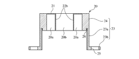
- FIG. 2 shows a first case 2 according to the first embodiment of the present invention.
- the first case 2 includes a first donut-shaped member 20 and a second donut-shaped member 30 that are assembled so as to form an annular portion.
- the first donut-shaped member 20 includes a donut-shaped upper plate portion 21, a double-wall cylindrical portion 22, And a plurality (a pair in the illustrated example) of leg portions 23 integrally extending downward from the outer surface of the double wall cylindrical portion 22 in parallel with the central axis C (z direction).
- the double wall cylindrical portion 22 has an outer cylindrical wall 22a and an inner cylindrical wall 22b that extend concentrically downward from the donut-shaped upper plate portion 21, and the donut-shaped upper plate portion 21, the concentric outer shape.
- the cylindrical wall 22a and the inner cylindrical wall 22b constitute a bottomed annular space 20a having an open lower end so as to partially accommodate the annular magnetic core.
- the inner cylindrical wall 22b constitutes a columnar space 20b.
- a pair of leg portions 23 are integrally extended from a position on the diameter of the outer surface of the outer cylindrical wall 22a (position 180 ° apart in plan view), and each leg portion 23 is an outer surface of the outer cylindrical wall 22a.
- a lateral projection 24 projecting from the side, an extension 23a extending downward from the side projection 24 in parallel to the central axis C, and horizontally outward from the tip of the extension 23a (a direction perpendicular to the central axis C).
- a fixing portion 23b extending in the direction.
- the extension 23a does not have to be completely parallel to the central axis C, and may be slightly inclined. In the illustrated example, there are a pair of leg portions 23, but the number of leg portions 23 may be three or more.
- the central angle of the leg portion 23 may not be 180 °.
- the fixed portion 23b is provided with a circular through hole 25 through which a bolt to be mounted on the mounted body is passed. A cutout may be formed in place of the through-hole 25 as long as it can be mounted on the mounted body.
- each leg 23 accommodates in the second case 4 a double-wall cylindrical portion 22 (a portion of the closed double-wall cylindrical portion 200 in the first donut-shaped member 20) wound with a coil.
- the dimensions are such that no interference occurs.
- the extension 23a has a dimension such that the bottom plate portion of the second case 4 and the bottom plate portion of the double wall cylindrical portion 22 are separated from each other at a predetermined interval. In the example shown in the figure, the dimensions of all the leg portions 23 are the same, but may be different as required.
- An arc-shaped groove 26 is provided on the lower surface of each side protrusion 24 at a position in contact with the inner surface of the extension 23a.
- the arc-shaped groove 26 has a shape for receiving an upper end edge of a cylindrical portion 42 of the second case 4 described later.
- the arc-shaped groove 26 is provided as necessary, but the arc-shaped groove 26 that receives the upper end edge of the cylindrical portion 42 ensures the positioning of the second case 4 with respect to the first case 2.
- the second donut-shaped member 30 includes a ring-shaped bottom plate portion 31 and an outer cylindrical shape that extends concentrically upward from the annular edge of the ring-shaped bottom plate portion 31. It has a wall 32 and an inner cylindrical wall 33, and the upper ends of both cylindrical walls 32, 33 are open. Similar to the first donut-shaped member 20, the cylindrical walls 32, 33 of the second donut-shaped member 30 also constitute a double-walled cylindrical portion, and the ring-shaped bottom plate portion 31, the outer cylindrical wall 32, and the inner cylindrical wall The annular magnetic core is partially accommodated in the bottomed annular space 30a formed by 33. The inner cylindrical wall 33 of the second donut-shaped member 30 forms a columnar space 30b.
- annular step 32a is provided at the approximate center of the outer surface of the outer cylindrical wall 32.
- the lower part is a thick outer cylindrical wall part 32b, and the upper part is a thin outer cylindrical wall part 32c.
- annular step 33a is provided substantially at the center of the inner surface of the inner cylindrical wall 33, the thicker inner cylindrical wall 33b below the annular step 33a, and the thinner inner cylindrical wall above. Part 33c.
- the presence of the first donut-shaped member 20 is determined.
- the bottom annular space 20a and the bottomed annular space 30a of the second donut-shaped member 30 are integrated to form a closed annular space 2a that accommodates the annular magnetic core.
- the annular magnetic core is accommodated in the annular portion 200 of the first case 2.
- the columnar space 20b of the first donut-shaped member 20 and the columnar space 30b of the second donut-shaped member 30 are integrated to form a central through hole 2b through which a conducting wire constituting the coil passes.
- the thin outer cylindrical wall portion 32c and the thin inner cylindrical wall portion 33c of the second donut-shaped member 30 have no gap. Because it is inserted, the outer surface of the outer cylindrical wall 22a and the thick outer cylindrical wall portion 32b of the first donut-shaped member 20 and the second donut-shaped member 30 after being assembled, and the inner cylindrical wall 22b and the thin inner cylindrical shape There is substantially no step on the inner surface of the wall 33c.
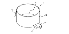
- the second case 4 includes a circular bottom plate portion 41, a cylindrical portion (cylinder portion) 42 that extends vertically upward from the annular edge of the circular bottom plate portion 41, and a circular shape.
- the bottom plate portion 41 has a pair of fixing portions 43 and 43 provided on the outer diameter of the bottom plate portion 41, and through holes 44 through which the bolts are passed.
- the through holes 44 of the fixing portions 43 of the second case 4 are located at positions corresponding to the through holes 25 of the fixing portions 23b of the first donut-shaped member 20 of the first case 2.
- a cutout may be used instead of the through hole 44.
- each extension 23a is preferably a curved surface along the outer surface of the cylindrical portion 42.
- the upper edge of the cylindrical portion 42 of the second case 4 is received in the arc-shaped groove 26 of the first donut-shaped member 20. Thereby, the cylindrical portion 42 of the second case 4 is in surface contact with the extension 23a of the leg portion 23, and the second case 4 can be accurately positioned.
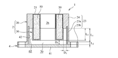
- the cylindrical portion 42 of the second case 4 spaced at a predetermined interval D 1 in the horizontal direction (xy direction) from the closed double wall cylindrical portion 200 of the first case 2, the bottom plate portion 41 of the second case 4
- the lower end of the first case 2 of the double-walled cylindrical portion 22 from the sum of the thickness L 2 of the length L 1 and the fixed portion 23b of the extension portion 23a of the leg portion 23 of the second donut-shaped member 30 thick cylindrical wall 32b, are spaced apart in the vertical direction (z-direction) at intervals D 2 obtained by subtracting the length L 3 of 33b.
- a space 65 is secured between the closed double-walled cylindrical portion 200 around which the coil is wound and the cylindrical portion 42 and the bottom plate portion 41 of the second case 4 and can be filled with potting resin.
- a space 70 for filling the potting resin is secured between the bottom surface of the closed double wall cylindrical portion 200 (the bottom plate portion 31 of the second donut-shaped member 30) and the top surface of the bottom plate portion 41 of the second case 4. Is done.
- the first case 2 and the second case 4 can be mounted on the mounted body with the through holes 25 and 44 being overlapped with each other.
- the first case 2 and the second case 4 are inserted by inserting fastening members such as bolts into the overlapped through holes 25 and 44. It is preferable that both are securely fixed to the mounted body.
- a bush may be fitted into the overlapped through holes 25 and 44 and fastened.
- the first donut-shaped member 20 and the second donut-shaped member 30 constituting the first case 2 are preferably formed of a resin having excellent insulating properties, heat resistance, flexibility, and moldability. Specifically, polyphenylene sulfide, liquid crystal polymer, polyethylene terephthalate, polybutylene terephthalate and the like are preferable. An injection molding method can be used for forming the first donut-shaped member 20 and the second donut-shaped member 30.
- a nonmagnetic metal having excellent thermal conductivity such as aluminum or its alloy, magnesium or its alloy, etc.
- the second case 4 it is necessary to provide a sufficient space between the coil and the second case 4, and the second case 4 must be enlarged.
- an insulator made of an insulating resin such as polyphenylene sulfide, polytetrafluoroethylene, or a liquid crystal polymer can be disposed between the coil and the second case 4 to narrow the gap between the coil and the second case 4. .
- the second case 4 from an insulating resin as well as the first case 2 in order to reduce the size and cost of the second case 4 in addition to the insulating properties.
- the use of insulating resin not only reduces the size of the case unit 1 by narrowing the distance between the second case 4 and the coil, but also reduces the manufacturing cost because it is easy to mold, and also the difference in thermal expansion from the potting resin Since there is little, a crack can be reduced.
- FIG. 11 shows a first donut-shaped member 120 of a first case 2 according to a second embodiment of the present invention.
- the first doughnut-shaped member 120 is different from the first donut-shaped member 20 of the first embodiment with respect to the structure of a plurality of (in the illustrated example, a pair) leg portions 123.
- the leg portion 123 includes a side protrusion 124 protruding from the outer cylindrical wall 22a, upper protrusions 125 and 126 integral with the side protrusion 124 and protruding from the donut-shaped upper plate portion 21, and a side protrusion. It has an extension part 123a that extends downward from 124 in parallel to the central axis C, and a fixing part 123b that extends horizontally outward from the tip of the extension part 123a. In order to ensure a sufficient winding area, each of the upper protrusions 125 and 126 has a shape that tapers toward the inside of the double-walled cylindrical portion 22 (on the columnar space 20b side).
- the pair of upper projecting portions 125 and 126 are preferably slightly higher than the coil wound around the double wall cylindrical portion 22 (the portion of the closed double wall cylindrical portion 200 in the first donut-shaped member 120). By comparing the height of the coil with the height of the upper protrusions 125 and 126, it can be determined whether the coil has been wound properly.
- the strength of the double wall cylindrical portion 22 is improved by the side protrusions 124 and the upper protrusions 125 and 126 that form thick portions in the axial direction and the radial direction of the double wall cylindrical portion 22.
- the pair of upper protrusions 125 and 126 can have different shapes.
- the first upward projecting portion 125 extends to partially cover the columnar space 20b of the double-walled cylindrical portion 22, and has two guide holes 131 and 132.
- the guide hole 131 is open to the cylindrical space 20b, and one end of the winding extending from the central through hole 2b of the first case 2 formed by joining the first donut-shaped member 120 to the second donut-shaped member 30 is inserted. Is done.
- the guide hole 132 opens into a recess 127 provided in the side protrusion 124, and the other end of the winding is inserted into a position outward from the double wall cylindrical portion 22.
- the guide holes 131 and 132 are through holes, but may be cutouts that open to the side.
- the guide holes 131 and 132 the end portion of the conducting wire wound around the double wall cylindrical portion 22 can be led out and positioned easily and with high accuracy. Further, by fixing both ends of the coil at a predetermined distance, high insulation resistance can be ensured even when a high voltage is applied to the coil.
- the guide hole 132 may be omitted, and the other end of the winding may be extended upward along the outer cylindrical wall 22a.
- the second upward projecting portion 126 extends partway through the donut-shaped upper plate portion 21 toward the central through hole 2b, and no guide hole is provided. Note that it is not necessary to provide the upper protrusions on all the leg parts 123, and for example, only the upper protrusions 125 having the guide holes 131 and 132 may be provided.
- FIGS. 12 (a) to 12 (c) show a second donut-shaped member 130 according to a third embodiment of the present invention.
- the second doughnut-shaped member 130 is a pair of lower projecting portions 34, 34 extending integrally from the bottom plate portion 131 so as to correspond to the upper projecting portions 125, 126 of the first donut-shaped member 120 of the second embodiment.
- Have Each downward protrusion 34 has a semicircular cross section so as to taper toward the cylindrical space 30b.
- the downward protrusions 34 and 34 can further suppress the deviation of the conductor in the outer cylindrical wall 32. Since portions other than the downward projecting portions 34 and 34 are substantially the same as those of the second donut-shaped member 30 of the first embodiment, description thereof is omitted.
- the first donut-shaped members 20 and 120 and the second donut-shaped members 30 and 130 are both cap-shaped accommodating the magnetic core. May be sized to accommodate the entire magnetic core.
- the second donut-shaped member 30, 130 is a bottom lid that closes the lower end opening of the first donut-shaped member 20, 120, or
- the second donut-shaped member 30, 130 is the first donut-shaped member 30, 130. Let the upper lid body close the upper-end opening part of the donut-shaped members 20 and 120. The case of (b) will be described in detail below as an example.
- the second donut-shaped member 230 having the lower opening is engaged with the first donut-shaped member 220 having the upper opening.
- the first case 2 formed by combining the first donut-shaped member 220 and the second donut-shaped member 230 has substantially the same appearance as the second embodiment.
- the first donut-shaped member 220 extends downward in parallel with the central axis C (z direction) from the outer surface of the donut-shaped lower plate portion 221, the double-wall cylindrical portion 222, and the double-wall cylindrical portion 222. And a plurality of legs (a pair in the illustrated example).
- the double-wall cylindrical portion 222 has an outer cylindrical wall 222a and an inner cylindrical wall 222b that extend concentrically upward from an annular edge of the donut-shaped lower plate portion 221.
- the concentric outer cylindrical wall 222a and inner cylindrical wall 222b constitute a bottomed annular space 220a having an open upper end so as to accommodate the annular magnetic core.
- the inner cylindrical wall 222b constitutes a columnar space 220b.
- the bottomed annular space 220a accommodates an annular magnetic core.
- the outer cylindrical wall 222a has an annular step 225a that is horizontal (perpendicular to the central axis C) on the inner surface near the upper end, and the inner cylindrical wall 222b is horizontal (perpendicular to the central axis C) near the upper end.
- the side protrusion 224 of each leg 223 has a recess 227 facing the upper end.
- the same pair of downward projections as in the third embodiment are provided on the donut-shaped lower plate portion 221 of the first donut-shaped member 220 at positions corresponding to the upper projecting portions 235 and 236 of the second donut-shaped member 230.
- a portion 34 is provided.
- the second donut-shaped member 230 that functions as a lid includes a donut-shaped upper plate portion 231, a concentric outer cylindrical wall 232 that extends downward from the donut-shaped upper plate portion 231 along the central axis C, and an inner side. And a cylindrical wall 233.
- the donut-shaped upper plate portion 231 has a pair of upper projecting portions 235 that are substantially the same as those in the second embodiment at positions where the donut-shaped upper plate portions 231 contact the side projecting portions 224 and 224 of the pair of leg portions 223 of the first donut-shaped member 220. , 236.
- the outer cylindrical wall 232 is annularly in contact with the inner surface of the outer cylindrical wall 222a of the first donut-shaped member 220.
- the inner cylindrical wall 233 contacts the inner surface of the inner cylindrical wall 222b of the first donut-shaped member 220 and contacts the annular step 225b.
- the first case 2 is obtained in which the annular magnetic core is accommodated in the closed double-walled cylindrical portion (annular portion).
- the annular magnetic core is omitted for simplification.
- a pair of guide holes 237 and 238 are provided in the upper projecting portion 235 of the second donut-shaped member 230 as in the second embodiment.
- the guide hole 237 opens into the cylindrical space 220b of the first donut-shaped member 220, and from the central through hole 2b of the first case 2 formed by coupling the first donut-shaped member 220 to the second donut-shaped member 230.
- One end of the outgoing winding is inserted.
- the guide hole 238 opens into a recess 227 provided in the side protrusion 224 of the first donut-shaped member 220, and the other end of the winding is inserted at a position outward from the double-wall cylindrical portion 22.
- the guide holes 237 and 238 are through-holes, but may be cutouts that open to the side.
- FIG. 16 shows a second case 14 according to a fifth embodiment of the present invention.
- the second case 14 includes a vertical cylindrical body (cylinder portion) 142 integrally having an annular bottom portion 141, and a bottom plate 146 fixed to the annular bottom portion 141.
- the cylindrical body 142 is provided with a vertical recess 145 for receiving the extension 23a of the leg 23 of the first case 2.
- the bottom plate 146 includes a circular portion 147 and a pair of fixing portions 43 and 43 protruding from both ends on the diameter thereof, and each fixing portion 43 corresponds to the through hole 25 of the leg portion 23.
- a circular through-hole 44 is provided at a position where it does.
- the bottom plate 146 may have a uniform thickness. It is preferable that the cylindrical body 142 is formed of an insulating resin as described above, and the bottom plate 146 is formed of a nonmagnetic metal such as aluminum, magnesium, stainless steel, or copper.
- the bottom plate 146 When the bottom plate 146 is fixed to the annular bottom portion 141 of the cylindrical body 142, the circular portion 147 of the bottom plate 146 is exposed from the central opening of the annular bottom portion 141, so that the bottom plate 146 can effectively function as a heat sink.
- the first case 2 and the second case 4 are assembled so that the extension 23a of the leg portion 23 of the first case 2 enters the vertical recess 145 of the cylindrical body 142, the through hole 25 of the first case 2 and the second case 14 are assembled.
- the case unit 1 thus obtained can be fixed to the mounted body with bolts.
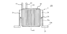
- FIG. 18 and 19 show a coil component 150 constituting the electronic component 100
- FIGS. 20 and 21 show the electronic component 100 in which the coil component 150 is accommodated in the second case 4.
- FIG. 18 in the coil component 150, both end portions 61 and 62 of the coil 60 are drawn upward (in the direction opposite to the fixing portion 23b of the leg portion 23) and connected to a terminal member (not shown).
- the drawing direction of the both ends 61 and 62 of the coil 60 is not limited, and for example, it may be drawn in the horizontal direction (the radial direction of the first case 2).
- the electronic component 100 includes a coil component 150 in which the coil 60 is wound around the first case 2 in which the annular magnetic core 50 is accommodated, and a second case 4 in which the coil component 150 is accommodated.
- the electronic component 100 is fixed to a mounted body 90 such as an aluminum frame with bolts 110 as shown in FIG.
- annular magnetic core 50 having substantially the same outer shape is arranged, and then the first The outer cylindrical wall 32 and the inner cylindrical wall 33 of the two donut-shaped members 30 are engaged with the outer cylindrical wall 22a and the inner cylindrical wall 22b of the first donut-shaped member 20.
- FIG. 7 the first case 2 in which the annular magnetic core 50 is accommodated in the closed annular space 2a of the closed double-wall cylindrical portion (annular portion) 200 is obtained.
- the annular magnetic core is omitted.
- annular magnetic core 50 As the annular magnetic core 50, (a) a laminated core of magnetic steel sheets, (b) an amorphous alloy ribbon such as an Fe-B-Si-C alloy or an Fe-B-Si-Cu-Nb alloy Nanocrystalline alloy ribbon toroidal core or laminated core, (c) Fe-B-Si-C alloy, Fe-B-Si-Cu-Nb alloy, Fe-Si alloy, Fe-Ni alloy, Molded core of soft magnetic Fe-based alloy powder such as Fe-Al alloy, Fe-Co alloy, Fe-Cr alloy, Fe-Si-M alloy (M is Cr or Al) and binder resin, (d) A ferrite core or the like can be used. A magnetic gap may be provided in the annular magnetic core 50 as necessary.
- an amorphous alloy ribbon such as an Fe-B-Si-C alloy or an Fe-B-Si-Cu-Nb alloy Nanocrystalline alloy ribbon toroidal core or laminated core
- the annular magnetic core 50 may be configured by arranging magnetic cores formed in a fan shape or a columnar shape in the annular space 30a via a plurality of magnetic gaps.
- the magnetic gap can be formed of a heat resistant resin, a nonmagnetic ceramic, an air gap or the like.
- a coil 60 is formed by winding a conducting wire (for example, enameled wire coated with polyamideimide on a copper wire) around the outer periphery of the closed double-walled cylindrical portion (annular portion) 200 of the first case 2 containing the annular magnetic core 50.
- the conducting wire forming the coil 60 may have various cross-sectional shapes such as a circular shape and a rectangular shape. However, if a conducting wire having a rectangular cross section is used, the space factor of the coil can be increased.
- the number of turns of the coil 60 is set as appropriate based on the required inductance, and the wire diameter is also appropriately selected according to the energized current.
- the entire magnetic core is accommodated in the annular space of the first case 2 made of insulating resin, sufficient insulation is ensured between the annular magnetic core and the coil 60, and a high voltage is applied to both ends of the coil 60. However, the problem of dielectric breakdown does not occur.
- one coil 60 is provided.
- another monitoring coil may be provided in the closed double-walled cylindrical portion 200.
- the number of coils corresponding to the number of inductors is provided. May be.
- the upper edge of the cylindrical portion (tubular portion) 42 of the second case 4 is inserted into the arc-shaped groove 26 of the side protrusion 24 of the leg portion 23 of the first case 2, and the second case 4 is inserted into the first case 2. Assemble. Therefore, the coil 60 needs to be in a region inside the arc-shaped groove 26 formed in the side protrusion 24 of the leg 23. Further, the coil 60 does not reach the upper surface of the bottom plate portion 41 of the second case 4 in the z direction. The coil 60 is partially covered by the second case 4.
- the bottom surface of the bottom plate portion 41 of the second case 4 is a mounting surface to the mounted body.
- the second case 4 is formed of an insulating resin, sufficient insulation is ensured even if the coil 60 and the second case 4 are close to each other, so the distance between the coil 60 and the mounted body can be shortened, and heat is released accordingly. Can increase the sex.
- the length of the leg portion 23 of the first case 2, the height of the cylindrical portion 42 of the second case 4, and the depth of the arc-shaped groove 26 of the first case 2 are determined by the fixed portion of the leg portion 23 of the first case 2.
- 23b is overlaid on the fixing part 43 of the second case 4
- the upper edge of the cylindrical part 42 of the second case 4 does not reach the back of the arc-shaped groove 26 of the first case 2
- the second case 4 does not need to completely cover the double-walled cylindrical portion 22 of the first case 2, and may cover at least a part.
- the liquid potting resin 80 is placed in the center of the coil component 150.
- the second case 4 is filled through the through hole 2b, and the coil 60 is immersed.
- the liquid potting resin 80 filled in the second case 4 is cured by heating.
- the potting resin 80 an epoxy resin, a silicone resin, a urethane resin, or the like can be used, but an insulating filler such as alumina having excellent thermal conductivity may be further blended. Since the viscosity of the potting resin 80 increases when a filler is blended, it is preferable to fill the heated potting resin 80 in the heated case unit 1. Air bubbles can be removed from the potting resin 80 by filling under reduced pressure.
- the space for filling the potting resin 80 be as narrow as possible to ensure sufficient insulation.
- the coil 60 and the cylindrical portion 42 and the bottom of the second case 4 The distance from 41 is preferably several mm or less. In order to fill the potting resin 80 in such a narrow space, it is necessary to take a sufficient time.
- the space for filling the potting resin 80 varies for each electronic component, and the insulation and heat dissipation of the electronic component are reduced.
- the case unit 1 of the present invention is used, accurate positioning of the coil component 150 can be easily and reliably performed. Therefore, in the electronic component using the case unit 1 of the present invention, there is no variation in the filling of the potting resin 80, so that cracks and holes in the potting resin 80 can be prevented.
- the potting resin 80 is filled to a height that can secure sufficient fixing strength.
- the first case 2 and the second case 4 are both fixed to the mounted body 90. It is not necessary to cover the entire part 150, and the amount of potting resin 80 can be reduced.
- the cylindrical portion 42 of the second case 4 is formed of an insulating resin, the potting resin 80 can have a small role in improving the insulating properties, and therefore the amount of the potting resin 80 can be further reduced.
- the liquid level of the potting resin 80 may be a position that is 1/4 or more of the height of the coil 60 and lower than the upper end of the cylindrical portion 42 of the second case 4.
- the potting resin 80 is filled up to the height of the joint between the first donut-shaped member 20 and the second donut-shaped member 30 constituting the first case 2, the hermeticity of the double-walled cylindrical portion 22 increases, and the Fe-based alloy It is possible to prevent rusting of the magnetic core.
- the mounted body 90 is provided with screw holes 125 into which the bolts 110 are inserted, corresponding to the through holes 25 of the first case 2 and the through holes 44 of the second case 4.
- the bolts 110 passed through the through holes 25 and 44 in a state where the fixing portions 23b of the leg portions 23 of the first case 2 and the fixing portions 43 of the second case 4 are overlapped are screwed into the screw holes 125 of the mounted body 90. Fix and fix.
- the heat generated by the coil 60 when energized is transmitted to the potting resin 80 and the second case 4 and radiated to the mounted body 90.
- an in-vehicle electronic component that operates with a large voltage and a large current can exhibit excellent insulation and heat dissipation and can be firmly fixed to a mounted body.
Landscapes
- Engineering & Computer Science (AREA)
- Power Engineering (AREA)
- Mechanical Engineering (AREA)
- Coils Or Transformers For Communication (AREA)
Priority Applications (4)
| Application Number | Priority Date | Filing Date | Title |
|---|---|---|---|
| EP13816996.6A EP2874162B1 (fr) | 2012-07-13 | 2013-07-16 | Unité de boîtier et composant électronique |
| CN201380037176.8A CN104471656B (zh) | 2012-07-13 | 2013-07-16 | 壳体单元以及电子部件 |
| US14/414,306 US9786425B2 (en) | 2012-07-13 | 2013-07-16 | Case unit and electronic device |
| JP2014524905A JP6128125B2 (ja) | 2012-07-13 | 2013-07-16 | ケースユニット及び電子部品 |
Applications Claiming Priority (2)
| Application Number | Priority Date | Filing Date | Title |
|---|---|---|---|
| JP2012-157398 | 2012-07-13 | ||
| JP2012157398 | 2012-07-13 |
Publications (1)
| Publication Number | Publication Date |
|---|---|
| WO2014010749A1 true WO2014010749A1 (fr) | 2014-01-16 |
Family
ID=49916187
Family Applications (1)
| Application Number | Title | Priority Date | Filing Date |
|---|---|---|---|
| PCT/JP2013/069261 Ceased WO2014010749A1 (fr) | 2012-07-13 | 2013-07-16 | Unité de boîtier et composant électronique |
Country Status (5)
| Country | Link |
|---|---|
| US (1) | US9786425B2 (fr) |
| EP (1) | EP2874162B1 (fr) |
| JP (1) | JP6128125B2 (fr) |
| CN (1) | CN104471656B (fr) |
| WO (1) | WO2014010749A1 (fr) |
Cited By (11)
| Publication number | Priority date | Publication date | Assignee | Title |
|---|---|---|---|---|
| JP2015198205A (ja) * | 2014-04-02 | 2015-11-09 | 株式会社タムラ製作所 | リアクトル |
| WO2016002326A1 (fr) * | 2014-07-04 | 2016-01-07 | 株式会社オートネットワーク技術研究所 | Ensemble bobine, structure de montage pour ensemble bobine et boîte de raccordement électrique |
| JP2016096227A (ja) * | 2014-11-13 | 2016-05-26 | 住友電気工業株式会社 | インダクタ |
| JP2016181594A (ja) * | 2015-03-24 | 2016-10-13 | 株式会社タムラ製作所 | インダクタ |
| JP2017034002A (ja) * | 2015-07-29 | 2017-02-09 | 株式会社タムラ製作所 | インダクタ |
| CN106920650A (zh) * | 2017-03-22 | 2017-07-04 | 三积瑞科技(苏州)有限公司 | 高品质组合式电感 |
| JP2018186281A (ja) * | 2018-06-26 | 2018-11-22 | 株式会社タムラ製作所 | リアクトル |
| JP2020109782A (ja) * | 2018-12-28 | 2020-07-16 | Tmp株式会社 | インダクタ、内側平角線片及び外側平角線片並びに製造方法 |
| SE543385C2 (en) * | 2017-05-12 | 2020-12-29 | Walbro Llc | Ignition device for an internal combustion engine enhanced to present cracks in the filling resin |
| JP2021153111A (ja) * | 2020-03-24 | 2021-09-30 | 三菱電機株式会社 | ケース、リアクトル、電子機器およびリアクトルの製造方法 |
| JP2022552687A (ja) * | 2019-10-15 | 2022-12-19 | スミダ・コンポーネンツ・アンド・モジュールズ・ゲゼルシャフト・ミット・ベシュレンクテル・ハフツング | コア実装部のための形状適合型リテーナおよびこれを用いて製造された誘導性構成要素 |
Families Citing this family (20)
| Publication number | Priority date | Publication date | Assignee | Title |
|---|---|---|---|---|
| US9636741B2 (en) * | 2007-04-19 | 2017-05-02 | Indimet, Inc. | Solenoid housing and method of providing a solenoid housing |
| KR20160126751A (ko) * | 2015-04-24 | 2016-11-02 | 삼성전기주식회사 | 코일 전자부품 및 그 제조방법 |
| DE102016110579A1 (de) * | 2016-06-08 | 2017-12-14 | Epcos Ag | Induktives Bauteil |
| JP6429917B2 (ja) * | 2017-02-16 | 2018-11-28 | 株式会社タムラ製作所 | コイル部品 |
| US11305663B2 (en) | 2017-03-27 | 2022-04-19 | General Electric Company | Energy efficient hands-free electric vehicle charger for autonomous vehicles in uncontrolled environments |
| CN106960722A (zh) * | 2017-05-02 | 2017-07-18 | 华建电气有限公司 | 穿心式电流互感器 |
| EP3483905B1 (fr) * | 2017-11-10 | 2020-07-15 | ABB Schweiz AG | Bobine d'arrêt |
| JP6903156B2 (ja) * | 2017-11-14 | 2021-07-14 | 三菱電機株式会社 | 電力変換装置 |
| CN111768960B (zh) * | 2019-04-01 | 2022-02-18 | 台达电子企业管理(上海)有限公司 | 灌封盒以及变压器 |
| CN111768959B (zh) | 2019-04-01 | 2022-03-08 | 台达电子企业管理(上海)有限公司 | 变压器 |
| CN111768947B (zh) | 2019-04-01 | 2023-03-24 | 台达电子企业管理(上海)有限公司 | 变压器及其制造方法 |
| US11978581B2 (en) * | 2019-07-09 | 2024-05-07 | Murata Manufacturing Co., Ltd. | Surface-mounted magnetic-component module |
| US12165798B2 (en) * | 2019-07-09 | 2024-12-10 | Murata Manufacturing Co., Ltd. | Surface-mounted magnetic-component module |
| CN110808140B (zh) * | 2019-11-08 | 2021-06-08 | 安徽昭田电子科技有限公司 | 一种纳米晶合金磁芯及其制造方法 |
| DE102020203093A1 (de) | 2020-03-11 | 2021-09-16 | Brose Fahrzeugteile SE & Co. Kommanditgesellschaft, Würzburg | Induktivität eines elektrischen Antriebs |
| JP7268638B2 (ja) * | 2020-05-15 | 2023-05-08 | 株式会社村田製作所 | インダクタ部品 |
| US11557419B2 (en) | 2020-06-23 | 2023-01-17 | Hamilton Sundstrand Corporation | Thermal management of inductor on a cold plate |
| US12548703B2 (en) * | 2021-02-22 | 2026-02-10 | Schaffner Emv Ag | Inductor module with improved thermal performances |
| JP7596927B2 (ja) * | 2021-05-24 | 2024-12-10 | 富士電機株式会社 | 電力変換装置およびトランス |
| CN114110239A (zh) * | 2021-12-21 | 2022-03-01 | 浙江辰午电子科技有限公司 | 一种防爆电磁阀线圈 |
Citations (7)
| Publication number | Priority date | Publication date | Assignee | Title |
|---|---|---|---|---|
| JPH1041140A (ja) * | 1996-07-23 | 1998-02-13 | Hitachi Ferrite Denshi Kk | コモンモードチョーク |
| JPH1050534A (ja) * | 1996-08-02 | 1998-02-20 | Tamura Seisakusho Co Ltd | トロイダルトランス |
| JPH11135347A (ja) * | 1997-10-30 | 1999-05-21 | Mitsubishi Electric Corp | 変流器 |
| JP2006262368A (ja) * | 2005-03-18 | 2006-09-28 | Tdk Corp | ノイズフィルタ |
| JP2010034228A (ja) | 2008-07-28 | 2010-02-12 | Sumitomo Electric Ind Ltd | リアクトル |
| JP2010114359A (ja) * | 2008-11-10 | 2010-05-20 | Sanden Corp | コイル構造体 |
| JP2011109499A (ja) * | 2009-11-19 | 2011-06-02 | Cosel Co Ltd | ノイズフィルタ |
Family Cites Families (10)
| Publication number | Priority date | Publication date | Assignee | Title |
|---|---|---|---|---|
| JPH0611316U (ja) * | 1992-07-15 | 1994-02-10 | 株式会社トーキン | 端子台付きトロイダルコイル |
| JPH1027722A (ja) * | 1996-07-09 | 1998-01-27 | Tokin Corp | ラインフィルタ |
| JP3295355B2 (ja) * | 1997-09-19 | 2002-06-24 | 東光株式会社 | 電子部品 |
| JP2000200721A (ja) * | 1999-01-07 | 2000-07-18 | Fuji Elelctrochem Co Ltd | コイル部品 |
| JP2003272924A (ja) * | 2002-03-18 | 2003-09-26 | Hitachi Metals Ltd | 台座付きコイル |
| JP2007234752A (ja) * | 2006-02-28 | 2007-09-13 | Denso Corp | コイル部品及びその製造方法 |
| JP4840921B2 (ja) * | 2006-10-10 | 2011-12-21 | Necトーキン株式会社 | インダクタンス素子 |
| JP2008172053A (ja) * | 2007-01-12 | 2008-07-24 | Tdk Corp | コイル部品 |
| JP4877616B2 (ja) * | 2009-09-17 | 2012-02-15 | Tdk株式会社 | コイル部品 |
| JP2011113995A (ja) * | 2009-11-24 | 2011-06-09 | Nec Tokin Corp | コア絶縁ケース及びコイル部品 |
-
2013
- 2013-07-16 EP EP13816996.6A patent/EP2874162B1/fr active Active
- 2013-07-16 WO PCT/JP2013/069261 patent/WO2014010749A1/fr not_active Ceased
- 2013-07-16 US US14/414,306 patent/US9786425B2/en active Active
- 2013-07-16 JP JP2014524905A patent/JP6128125B2/ja active Active
- 2013-07-16 CN CN201380037176.8A patent/CN104471656B/zh active Active
Patent Citations (7)
| Publication number | Priority date | Publication date | Assignee | Title |
|---|---|---|---|---|
| JPH1041140A (ja) * | 1996-07-23 | 1998-02-13 | Hitachi Ferrite Denshi Kk | コモンモードチョーク |
| JPH1050534A (ja) * | 1996-08-02 | 1998-02-20 | Tamura Seisakusho Co Ltd | トロイダルトランス |
| JPH11135347A (ja) * | 1997-10-30 | 1999-05-21 | Mitsubishi Electric Corp | 変流器 |
| JP2006262368A (ja) * | 2005-03-18 | 2006-09-28 | Tdk Corp | ノイズフィルタ |
| JP2010034228A (ja) | 2008-07-28 | 2010-02-12 | Sumitomo Electric Ind Ltd | リアクトル |
| JP2010114359A (ja) * | 2008-11-10 | 2010-05-20 | Sanden Corp | コイル構造体 |
| JP2011109499A (ja) * | 2009-11-19 | 2011-06-02 | Cosel Co Ltd | ノイズフィルタ |
Non-Patent Citations (1)
| Title |
|---|
| See also references of EP2874162A4 |
Cited By (18)
| Publication number | Priority date | Publication date | Assignee | Title |
|---|---|---|---|---|
| JP2015198205A (ja) * | 2014-04-02 | 2015-11-09 | 株式会社タムラ製作所 | リアクトル |
| CN106030734B (zh) * | 2014-07-04 | 2018-01-19 | 株式会社自动网络技术研究所 | 线圈组装体、线圈组装体的安装构造以及电连接箱 |
| WO2016002326A1 (fr) * | 2014-07-04 | 2016-01-07 | 株式会社オートネットワーク技術研究所 | Ensemble bobine, structure de montage pour ensemble bobine et boîte de raccordement électrique |
| CN106030734A (zh) * | 2014-07-04 | 2016-10-12 | 株式会社自动网络技术研究所 | 线圈组装体、线圈组装体的安装构造以及电连接箱 |
| EP3067904A4 (fr) * | 2014-07-04 | 2016-12-28 | Autonetworks Technologies Ltd | Ensemble bobine, structure de montage pour ensemble bobine et boîte de raccordement électrique |
| JP6061172B2 (ja) * | 2014-07-04 | 2017-01-18 | 株式会社オートネットワーク技術研究所 | コイル組立体、コイル組立体の取り付け構造、および、電気接続箱 |
| US10304606B2 (en) | 2014-07-04 | 2019-05-28 | Autonetworks Technologies, Ltd. | Coil assembly, structure for attaching coil assembly, and electrical connection box |
| JP2016096227A (ja) * | 2014-11-13 | 2016-05-26 | 住友電気工業株式会社 | インダクタ |
| JP2016181594A (ja) * | 2015-03-24 | 2016-10-13 | 株式会社タムラ製作所 | インダクタ |
| JP2017034002A (ja) * | 2015-07-29 | 2017-02-09 | 株式会社タムラ製作所 | インダクタ |
| CN106920650A (zh) * | 2017-03-22 | 2017-07-04 | 三积瑞科技(苏州)有限公司 | 高品质组合式电感 |
| CN106920650B (zh) * | 2017-03-22 | 2018-09-28 | 三积瑞科技(苏州)有限公司 | 高品质组合式电感 |
| SE543385C2 (en) * | 2017-05-12 | 2020-12-29 | Walbro Llc | Ignition device for an internal combustion engine enhanced to present cracks in the filling resin |
| JP2018186281A (ja) * | 2018-06-26 | 2018-11-22 | 株式会社タムラ製作所 | リアクトル |
| JP2020109782A (ja) * | 2018-12-28 | 2020-07-16 | Tmp株式会社 | インダクタ、内側平角線片及び外側平角線片並びに製造方法 |
| JP2022552687A (ja) * | 2019-10-15 | 2022-12-19 | スミダ・コンポーネンツ・アンド・モジュールズ・ゲゼルシャフト・ミット・ベシュレンクテル・ハフツング | コア実装部のための形状適合型リテーナおよびこれを用いて製造された誘導性構成要素 |
| JP2021153111A (ja) * | 2020-03-24 | 2021-09-30 | 三菱電機株式会社 | ケース、リアクトル、電子機器およびリアクトルの製造方法 |
| JP7437989B2 (ja) | 2020-03-24 | 2024-02-26 | 三菱電機株式会社 | ケース、リアクトル、電子機器およびリアクトルの製造方法 |
Also Published As
| Publication number | Publication date |
|---|---|
| EP2874162B1 (fr) | 2017-06-07 |
| EP2874162A4 (fr) | 2016-04-27 |
| US20150213938A1 (en) | 2015-07-30 |
| JPWO2014010749A1 (ja) | 2016-06-23 |
| US9786425B2 (en) | 2017-10-10 |
| EP2874162A1 (fr) | 2015-05-20 |
| CN104471656B (zh) | 2017-04-26 |
| CN104471656A (zh) | 2015-03-25 |
| JP6128125B2 (ja) | 2017-05-17 |
Similar Documents
| Publication | Publication Date | Title |
|---|---|---|
| JP6128125B2 (ja) | ケースユニット及び電子部品 | |
| JP5179561B2 (ja) | リアクトル装置 | |
| CN107210118B (zh) | 电抗器 | |
| CN107533900A (zh) | 电抗器 | |
| JP2019165148A (ja) | 電力変換装置 | |
| JP2015138817A (ja) | 巻線部品 | |
| JP6621056B2 (ja) | リアクトル、およびリアクトルの製造方法 | |
| CN110326071A (zh) | 电抗器 | |
| JP6278250B2 (ja) | リアクトル | |
| JP5288325B2 (ja) | リアクトル集合体、及びコンバータ | |
| CN109564815B (zh) | 电抗器 | |
| JP6570982B2 (ja) | リアクトル | |
| WO2017213196A1 (fr) | Réacteur et son procédé de fabrication | |
| US12002612B2 (en) | Reactor | |
| US12148559B2 (en) | Reactor | |
| JP6512188B2 (ja) | リアクトル | |
| JP6362030B2 (ja) | リアクトル | |
| JP7629067B1 (ja) | 絶縁型コンバータ | |
| US20240206026A1 (en) | Electronic component | |
| JP6436352B2 (ja) | リアクトル | |
| JP2018139332A (ja) | リアクトル、およびリアクトルの製造方法 | |
| JP2016100539A (ja) | チョークコイル、およびチョークコイルの製造方法 | |
| JP2025187648A (ja) | コイル部品 | |
| JP2024147896A (ja) | リアクトル | |
| JP2025059944A (ja) | 絶縁型コンバータ |
Legal Events
| Date | Code | Title | Description |
|---|---|---|---|
| 121 | Ep: the epo has been informed by wipo that ep was designated in this application |
Ref document number: 13816996 Country of ref document: EP Kind code of ref document: A1 |
|
| ENP | Entry into the national phase |
Ref document number: 2014524905 Country of ref document: JP Kind code of ref document: A |
|
| WWE | Wipo information: entry into national phase |
Ref document number: 14414306 Country of ref document: US |
|
| NENP | Non-entry into the national phase |
Ref country code: DE |
|
| REEP | Request for entry into the european phase |
Ref document number: 2013816996 Country of ref document: EP |
|
| WWE | Wipo information: entry into national phase |
Ref document number: 2013816996 Country of ref document: EP |