WO2014013554A1 - Dispositif de commande et procédé de commande - Google Patents
Dispositif de commande et procédé de commande Download PDFInfo
- Publication number
- WO2014013554A1 WO2014013554A1 PCT/JP2012/068129 JP2012068129W WO2014013554A1 WO 2014013554 A1 WO2014013554 A1 WO 2014013554A1 JP 2012068129 W JP2012068129 W JP 2012068129W WO 2014013554 A1 WO2014013554 A1 WO 2014013554A1
- Authority
- WO
- WIPO (PCT)
- Prior art keywords
- data
- control
- unit
- blocking
- monitoring
- Prior art date
- Legal status (The legal status is an assumption and is not a legal conclusion. Google has not performed a legal analysis and makes no representation as to the accuracy of the status listed.)
- Ceased
Links
Images


Classifications
-
- G—PHYSICS
- G05—CONTROLLING; REGULATING
- G05B—CONTROL OR REGULATING SYSTEMS IN GENERAL; FUNCTIONAL ELEMENTS OF SUCH SYSTEMS; MONITORING OR TESTING ARRANGEMENTS FOR SUCH SYSTEMS OR ELEMENTS
- G05B19/00—Program-control systems
- G05B19/02—Program-control systems electric
- G05B19/18—Numerical control [NC], i.e. automatically operating machines, in particular machine tools, e.g. in a manufacturing environment, so as to execute positioning, movement or co-ordinated operations by means of program data in numerical form
- G05B19/401—Numerical control [NC], i.e. automatically operating machines, in particular machine tools, e.g. in a manufacturing environment, so as to execute positioning, movement or co-ordinated operations by means of program data in numerical form characterised by control arrangements for measuring, e.g. calibration and initialisation, measuring workpiece for machining purposes
-
- G—PHYSICS
- G05—CONTROLLING; REGULATING
- G05B—CONTROL OR REGULATING SYSTEMS IN GENERAL; FUNCTIONAL ELEMENTS OF SUCH SYSTEMS; MONITORING OR TESTING ARRANGEMENTS FOR SUCH SYSTEMS OR ELEMENTS
- G05B9/00—Safety arrangements
- G05B9/02—Safety arrangements electric
-
- G—PHYSICS
- G05—CONTROLLING; REGULATING
- G05B—CONTROL OR REGULATING SYSTEMS IN GENERAL; FUNCTIONAL ELEMENTS OF SUCH SYSTEMS; MONITORING OR TESTING ARRANGEMENTS FOR SUCH SYSTEMS OR ELEMENTS
- G05B2219/00—Program-control systems
- G05B2219/20—Pc systems
- G05B2219/23—Pc programming
- G05B2219/23098—Manual control, via microprocessor instead of direct connection to actuators
Definitions
- the present invention relates to a control device and a control method.
- Patent Document 1 Some control devices that control control target devices such as mechanical devices and plants perform double monitoring of communication data transmitted and received via a communication network in order to improve safety (see, for example, Patent Document 1).
- the safety control system disclosed in Patent Document 1 is connected to an external controller via a network, and a safety signal from the external controller is dually processed by two processors to form a duplex system. The sex is secured.
- the safety control system is configured for one network that communicates with an external controller. That is, an external controller is only connected to the safety control system via one network.
- a general control device may be connected to a plurality of networks and may need to communicate with a plurality of devices.
- a motor control device that controls a motor
- an encoder that detects the rotation angle of the motor and a linear scale that detects the machine position may be connected via a network.
- the control device needs to support three networks.
- the present invention has been made in view of the above, and a control device that can monitor data received from a plurality of networks in a duplex system and can safely stop a device to be controlled when there is an abnormality in communication data, and The purpose is to obtain a control method.
- a control device performs an operation based on data from a plurality of measurement control devices connected via a plurality of networks, and outputs an operation signal to the control target device.
- a control device connected to each of the plurality of measurement control devices, and a plurality of communication means for receiving data from the measurement control device, and the control target device based on the data input from the communication means Based on the data acquired at a predetermined timing from the storage means, the control means for calculating an operation signal for controlling the control signal, and outputting the operation signal to the control target device; the storage means for storing the data input from the communication means; Calculate a calculated value by performing a predetermined calculation, determine whether the calculated value satisfies a blocking condition for blocking the operation signal, and satisfy the blocking condition In response to the cutoff signal output from at least one of the first monitoring means and the second monitoring means independent of each other for outputting the cutoff signal, and the first monitoring means and the second monitoring means, from the control means And a blocking unit that blocks
- the storage means for temporarily storing the data received by the communication means is provided, the first monitoring means and the second monitoring means perform calculations based on the data acquired from the storage means at a predetermined timing, When the calculation result satisfies the cutoff condition, it is configured to output a cutoff signal for stopping the controlled device, so it is possible to monitor communication data received from multiple networks, and there is an abnormality in the communication data In this case, the control target device can be safely stopped.
- FIG. 1 is a block diagram schematically illustrating an example of a configuration of a control system including a control device according to the first embodiment.
- FIG. 2 is a flowchart illustrating an example of the procedure of the monitoring process according to the first embodiment.
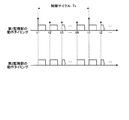
- FIG. 3 is a timing chart illustrating an example of operation timings of the first monitoring unit and the second monitoring unit.
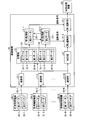
- FIG. 4 is a block diagram schematically showing an example of the configuration of a control system having a control device according to the second embodiment.
- FIG. 1 is a block diagram schematically illustrating an example of a configuration of a control system including a control device according to the first embodiment.
- the control system includes a control device 10, a control target device 20, and measurement control devices 30-1 to 30-N (N is an integer of 2 or more).
- the control device 10 is connected to the control target device 20 and controls the operation of the control target device 20.
- Examples of the control target device 20 include a motor that drives a mechanical device.
- FIG. 1 shows a case where the control target device 20 is configured by a motor.
- the control device 10 is connected to a plurality of measurement control devices 30-1 to 30-N via the networks 40-1 to 40-N, and is based on data from the measurement control devices 30-1 to 30-N.
- the operation signal for controlling the control target device 20 is output.
- the measurement control devices 30-1 to 30-N are configured by a controller that outputs data for driving the control target device 20, a sensor that detects the operation state of the control target device 20, and the like. 31-1 to 31-N are transmitted. Examples of the measurement control devices 30-1 to 30-N include an external controller that outputs a command for operating the control target device 20, and a sensor such as an encoder that detects the rotation angle of the motor that configures the control target device 20. Can do.
- the measurement control device 30-1 is configured by an external controller
- the measurement control device 30-2 is configured by an encoder.
- the control device 10 includes communication units 11-1 to 11-N, a control unit 12, a storage unit 13, a first monitoring unit 14-1, a second monitoring unit 14-2, and a first blocking unit 15-. 1 and a second blocking part 15-2.
- the communication units 11-1 to 11-N are connected to the measurement control devices 30-1 to 30-N via the networks 40-1 to 40-N, and the measurement control devices 30-1 to 30-N. Receive data from.
- the control unit 12 outputs an operation signal for controlling the control target device 20 based on the data received by the communication units 11-1 to 11-N. For example, the position control calculation is performed so that the rotation angle of the motor input from the encoder (measurement control device 30-2) follows the position command input from the external controller (measurement control device 30-1), and the operation signal power Is output to the motor (control target device 20).
- the control part 12 is comprised by CPU (Central Processing Unit), for example.
- the storage unit 13 temporarily stores the data 31-1 to 31-N received by the communication units 11-1 to 11-N at a predetermined address determined for each measurement control device 30-1 to 30-N.
- the first monitoring unit 14-1 and the second monitoring unit 14-2 both receive the data 31-1 to 31-N stored in the storage unit 13 at a predetermined timing, and receive the data 31-1 to 31-N. The calculation is performed based on the calculation result, it is determined whether the calculation result satisfies the cutoff condition, and the output of the cutoff signal for blocking the output of the operation signal to the control target device 20 is controlled.
- the first monitoring unit 14-1 and the second monitoring unit 14-2 are configured by independent CPUs different from the control unit 12, for example.
- the blocking conditions are, for example, the following cases (1) to (4).
- the calculation method using the data 31-1 to 31-N is defined in advance for each blocking condition, and the calculation process is performed based on the calculation method.
- the blocking signal output from the first monitoring unit 14-1 is input to the first blocking unit 15-1
- the blocking signal output from the second monitoring unit 14-2 is input to the second blocking unit 15-2.
- the first monitoring unit 14-1 and the second monitoring unit 14-2 have a function of passing data input to each other and opposing whether or not they are the same.
- the first blocking unit 15-1 and the second blocking unit 15-2 block the operation signal output from the control unit 12 to the control target device 20 and stop the control target device 20 .
- a cutoff signal is output from at least one of the first monitoring unit 14-1 and the second monitoring unit 14-2, the operation signal output by the control unit 12 is blocked and the operation signal is input to the control target device 20.
- the control target device 20 stops.
- a first blocking unit 15-1 connected to the first monitoring unit 14-1 and a second blocking unit 15-2 connected to the second monitoring unit 14-2 are connected in series. Although it is configured to be connected, one blocking unit is connected, and the first monitoring unit 14-1 and the second monitoring unit 14-2 are connected to this blocking unit, and the first monitoring unit 14-1
- the operation signal may be blocked when a blocking signal is received from one of the second monitoring units 14-2.
- Each of the communication units 11-1 to 11-N receives data 31-1 to 31-N from the measurement control devices 30-1 to 30-N via the networks 40-1 to 40-N.
- the control unit 12 acquires data 31-1 to 31-N in order from each of the communication units 11-1 to 11-N at a predetermined timing, calculates operation data for controlling the control target device 20, and outputs it as an operation signal To do. As long as the operation signal is not blocked by the monitoring process described later, the control target device 20 is controlled according to the operation signal.
- the first monitoring unit 14-1 and the second monitoring unit 14-2 also receive data 31-1 to 31-N received from the communication units 11-1 to 11-N.
- a monitoring process is performed to determine whether to stop control of the control target device 20 by the control unit 12.
- FIG. 2 is a flowchart illustrating an example of the procedure of the monitoring process according to the first embodiment.
- FIG. 3 is a timing chart showing an example of operation timings of the first monitoring unit and the second monitoring unit.
- the horizontal axis represents time
- the vertical axis represents an on / off state.
- Ts is a control cycle.
- the control device 10 performs an operation using the data 31-1, outputs an operation signal to the control target device 20, and then performs an operation using the data 31-2, and outputs an operation signal to the control target device 20.
- the control cycle Ts is repeated.
- the first monitoring unit 14-1 is configured to accept N interrupts.
- t1 to tN are timings at which N interrupts are generated.
- N interrupts are generated at predetermined time intervals (Ts / N) as shown in FIG.
- the first monitoring unit 14-1 acquires the data 31-1 corresponding to the time t1 from the storage unit 13, and is preset for the data 31-1.
- Calculation is performed (step S14).
- the second monitoring unit 14-2 acquires the data 31-1 corresponding to the time t1 from the storage unit 13 in synchronization with the first monitoring unit 14-1, and is preset for the data 31-1.
- Calculation is performed (step S15).
- the data acquired by the first monitoring unit 14-1 and the second monitoring unit 14-2 is the same data 31-1 in the storage unit 13.
- the first monitoring unit 14-1 and the second monitoring unit 14-2 independently determine whether the calculated value satisfies the blocking condition (steps S16 and S18).
- the blocking condition is a condition as exemplified in the above (1) to (4).
- both the first monitoring unit 14-1 and the second monitoring unit 14-2 determine that the calculated value does not satisfy the blocking condition (when both are NO in steps S16 and S18)
- control using the data 31-1 is performed. Since the process is normal, the control process by the control unit 12 is continued as it is.
- the first monitoring unit 14-1 receives data 31-i corresponding to the timing ti of each interrupt from the storage unit 13.
- the second monitoring unit 14-2 receives the same data 31-i from the storage unit 13 in synchronization with the first monitoring unit 14-1. Then, the first monitoring unit 14-1 and the second monitoring unit 14-2 perform arithmetic processing based on the input data 31-i, respectively, and wait until the next interrupt occurs if the interruption condition is not satisfied. Repeatedly.
- step S16 determines that the calculated value satisfies the blocking condition (Yes in step S16)
- the first monitoring unit 14-1 determines that the first blocking unit 15- A cut-off signal is output to 1 (step S17).
- the first blocking unit 15-1 blocks the operation signal output from the control unit 12 so that it does not reach the control target device 20.
- step S18 When the second monitoring unit 14-2 determines in step S18 that the calculated value satisfies the blocking condition (Yes in step S18), the second monitoring unit 14-2 sets the second blocking unit 15- A shut-off signal is output to 2 (step S19). Upon receiving the blocking signal, the second blocking unit 15-2 blocks the operation signal output from the control unit 12 so that it does not reach the control target device 20.
- step S17 or step S19 since the operation target signal from the control device 10 is not input to the control target device 20, the control target device 20 stops. Thus, the monitoring process by the control device 10 ends.
- the plurality of measurement control devices 30-1 to 30-N in the control device 10 connected to the plurality of measurement control devices 30-1 to 30-N via the networks 40-1 to 40-N, the plurality of measurement control devices 30-1 to 30-N.
- the storage unit 13 temporarily stores data 31-1 to 31-N input from the communication units 11-1 to 11-N connected to N.
- the first monitoring unit 14-1 and the second monitoring unit 14-2 perform calculations based on the data 31-1 to 31-N input from the storage unit 13 at a predetermined timing, and the calculated values are the cutoff conditions. When satisfy
- the data 31-1 to 31-N input from the plurality of networks 40-1 to 40-N can be double-monitored by the first monitoring unit 14-1 and the second monitoring unit 14-2.
- the control target device 20 can be safely stopped based on the data 31-1 to 31-N.
- N interrupts are generated at predetermined time intervals.
- data 31-1 to 31-N from the measurement control devices 30-1 to 30-N are respectively communicated.
- An interrupt may be generated at the timing input to the units 11-1 to 11-N.
- the priority order of N interrupts can be set according to the importance of the data 31-1 to 31-N input from each of the measurement control devices 30-1 to 30-N. By setting the priority order in this way, highly urgent data is preferentially processed, and the safety can be further improved.
- FIG. FIG. 4 is a block diagram schematically showing an example of the configuration of a control system having a control device according to the second embodiment.
- each measurement control device 30-1 to 30-N stores first data 32-1 to 32-N and second data 33-1 to 33-N, which are two data representing the same information. Generate and output.
- the first data 32-1 to 32-N and the second data 33-1 to 33-N are data representing the same information, but may be exactly the same data generated by the same processing unit or the same algorithm. The same information may be generated by different processing units or different algorithms.
- the storage unit 13 includes a first data storage area 131 for storing the first data 32-1 to 32-N, And a second data storage area 132 for storing second data 33-1 to 33-N.
- the first data 32-1 to 32-N received by the communication units 11-1 to 11-N are stored at predetermined addresses in the first data storage area 131, and the communication units 11-1 to 11-N are stored.
- the second data 33-1 to 33-N received by is stored at a predetermined address in the second data storage area 132.
- the first monitoring unit 14-1 performs calculations using the first data 32-1 to 32-N in the first data storage area 131 of the storage unit 13, and the second monitoring unit 14-2 includes the storage unit 13 The calculation is performed using the second data 33-1 to 33-N in the second data storage area 132. Further, the first monitoring unit 14-1 and the second monitoring unit 14-2 determine whether or not the calculation result satisfies the blocking condition, and determines whether or not to interrupt the output of the operation signal to the control target device 20. judge. In the case of blocking, a blocking signal is output for each.
- the blocking conditions are, for example, the following cases (5) to (8). (5) The case where the data from the measurement control devices 30-1 to 30-N commands to stop the control target device 20.
- a communication error is detected in data input from the measurement control devices 30-1 to 30-N.
- the data input by the first monitoring unit 14-1 and the data input by the second monitoring unit 14-2 are collated with each other, and the information represented by the two is not the same. For example, before the first monitoring unit 14-1 and the second monitoring unit 14-2 acquire the first data 32-i and the second data 33-i and perform the calculation, respectively, When it is mutually collated that 32-i and the second data 33-i represent the same information, and it cannot be determined that the first data 32-i and the second data 33-i represent the same information.
- (8) When the input data satisfies a predetermined condition For example, when the motor speed input from one measurement control device exceeds a predetermined value, or when the difference between the position command from one measurement control device and the feedback position from another measurement control device exceeds a predetermined value.
- control unit 12 may perform calculations using the first data 32-1 to 32-N, or may perform calculations using the second data 33-1 to 33-N.
- symbol is attached
- control process and the monitoring process in the control device 10 having such a configuration are also calculated by the first monitoring unit 14-1 using the first data 32-1 to 32-N, and the second monitoring unit 14-2 performs the first processing. Except for the point that calculation is performed using the two data 33-1 to 33-N, it is the same as that described in the first embodiment, and thus detailed description thereof is omitted.
- the plurality of measurement control devices 30-1 to 30-N in the control device 10 connected to the plurality of measurement control devices 30-1 to 30-N via the networks 40-1 to 40-N, the plurality of measurement control devices 30-1 to 30-N.
- the first monitoring unit 14-1 performs an operation based on the first data 32-1 to 32-N input from the first data storage area 131 at a predetermined timing
- the second monitoring unit 14-2 The calculation is performed based on the second data 33-1 to 33-N input from the second data storage area 132 at a predetermined timing, and the control target device 20 is stopped when the calculated value satisfies the cutoff condition.
- Each signal is output.
- the monitoring is performed using the two data obtained from the measurement control devices 30-1 to 30-N. If the received data is highly likely to be abnormal, the control unit 12 performs the control. There is an effect that an operation signal transmitted to the target device 20 can be blocked.
- control device is suitable for use as a control device for controlling a control target device such as a mechanical device or a plant.
- control device 11-1 to 11-N communication unit, 12 control unit, 13 storage unit, 14-1 first monitoring unit, 14-2 second monitoring unit, 15-1 first blocking unit, 15-2 first 2 interrupting units, 20 controlled devices, 30-1 to 30-N measurement control devices, 31-1 to 31-N, 32-1 to 32-N, 33-1 to 33-N data, 40-1 to 40 -N network, 131 first data storage area, 132 second data storage area.
Landscapes
- Engineering & Computer Science (AREA)
- Physics & Mathematics (AREA)
- General Physics & Mathematics (AREA)
- Automation & Control Theory (AREA)
- Human Computer Interaction (AREA)
- Manufacturing & Machinery (AREA)
- Safety Devices In Control Systems (AREA)
- Arrangements For Transmission Of Measured Signals (AREA)
- Programmable Controllers (AREA)
Abstract
Priority Applications (7)
| Application Number | Priority Date | Filing Date | Title |
|---|---|---|---|
| PCT/JP2012/068129 WO2014013554A1 (fr) | 2012-07-17 | 2012-07-17 | Dispositif de commande et procédé de commande |
| CN201280074738.1A CN104471495B (zh) | 2012-07-17 | 2012-07-17 | 控制装置以及控制方法 |
| US14/400,940 US9869991B2 (en) | 2012-07-17 | 2012-07-17 | Control device and control method for blocking a control signal to a target device |
| KR1020157001048A KR101688749B1 (ko) | 2012-07-17 | 2012-07-17 | 제어 장치 및 제어 방법 |
| DE112012006715.0T DE112012006715T5 (de) | 2012-07-17 | 2012-07-17 | Steuervorrichtung und Steuerverfahren |
| JP2014525589A JP5769885B2 (ja) | 2012-07-17 | 2012-07-17 | 制御装置および制御方法 |
| TW101150428A TWI479289B (zh) | 2012-07-17 | 2012-12-27 | 控制裝置及控制方法 |
Applications Claiming Priority (1)
| Application Number | Priority Date | Filing Date | Title |
|---|---|---|---|
| PCT/JP2012/068129 WO2014013554A1 (fr) | 2012-07-17 | 2012-07-17 | Dispositif de commande et procédé de commande |
Publications (1)
| Publication Number | Publication Date |
|---|---|
| WO2014013554A1 true WO2014013554A1 (fr) | 2014-01-23 |
Family
ID=49948409
Family Applications (1)
| Application Number | Title | Priority Date | Filing Date |
|---|---|---|---|
| PCT/JP2012/068129 Ceased WO2014013554A1 (fr) | 2012-07-17 | 2012-07-17 | Dispositif de commande et procédé de commande |
Country Status (7)
| Country | Link |
|---|---|
| US (1) | US9869991B2 (fr) |
| JP (1) | JP5769885B2 (fr) |
| KR (1) | KR101688749B1 (fr) |
| CN (1) | CN104471495B (fr) |
| DE (1) | DE112012006715T5 (fr) |
| TW (1) | TWI479289B (fr) |
| WO (1) | WO2014013554A1 (fr) |
Cited By (4)
| Publication number | Priority date | Publication date | Assignee | Title |
|---|---|---|---|---|
| JP2017094445A (ja) * | 2015-11-24 | 2017-06-01 | 株式会社デンソーウェーブ | ロボット制御装置 |
| WO2018139627A1 (fr) * | 2017-01-30 | 2018-08-02 | オムロン株式会社 | Système de sécurité et contrôleur de sécurité |
| US10065832B2 (en) | 2013-09-27 | 2018-09-04 | Mitsubishi Electric Corporation | Elevator control apparatus |
| JP2019514709A (ja) * | 2016-04-24 | 2019-06-06 | フランカ エミカ ゲーエムベーハーFRANKA EMIKA GmbH | ロボット制御システムおよび方法 |
Families Citing this family (6)
| Publication number | Priority date | Publication date | Assignee | Title |
|---|---|---|---|---|
| JP2019040435A (ja) * | 2017-08-25 | 2019-03-14 | アズビル株式会社 | 調節計および劣化位置検出方法 |
| JP6933183B2 (ja) * | 2018-03-30 | 2021-09-08 | オムロン株式会社 | セーフティ制御システムおよびセーフティ制御ユニット |
| WO2019207773A1 (fr) * | 2018-04-27 | 2019-10-31 | 三菱電機株式会社 | Dispositif de traitement de données, procédé de surveillance et programme |
| WO2020105337A1 (fr) * | 2018-11-21 | 2020-05-28 | パナソニックIpマネジメント株式会社 | Système de commande de moteur, aéronef sans pilote, corps mobile, et procédé de commande de moteur |
| JP7354601B2 (ja) * | 2019-06-10 | 2023-10-03 | マツダ株式会社 | 車載ネットワークシステム |
| JP7630613B2 (ja) * | 2021-05-20 | 2025-02-17 | 三菱電機モビリティ株式会社 | 制御装置 |
Citations (3)
| Publication number | Priority date | Publication date | Assignee | Title |
|---|---|---|---|---|
| JP2004148488A (ja) * | 2002-10-08 | 2004-05-27 | Fanuc Ltd | ロボット制御装置 |
| JP2011028571A (ja) * | 2009-07-27 | 2011-02-10 | Panasonic Electric Works Co Ltd | 監視制御装置 |
| JP2011188623A (ja) * | 2010-03-08 | 2011-09-22 | Fuji Electric Co Ltd | 安全制御システム |
Family Cites Families (25)
| Publication number | Priority date | Publication date | Assignee | Title |
|---|---|---|---|---|
| JPH04291859A (ja) | 1991-03-20 | 1992-10-15 | Fujitsu Ltd | 割り込み要求の制御方法 |
| JPH0740348U (ja) | 1993-12-29 | 1995-07-18 | 株式会社京三製作所 | 電子連動装置 |
| JPH10340102A (ja) | 1997-06-09 | 1998-12-22 | East Japan Railway Co | シリアル通信装置 |
| EP1037208B1 (fr) * | 1998-10-05 | 2010-03-10 | Teac Corporation | Appareil de conversion de donnees avec circuit de securite |
| JP2000299716A (ja) | 1999-04-14 | 2000-10-24 | Toshiba Corp | データ受信装置及びデータ受信方法 |
| JP4100108B2 (ja) * | 2002-09-12 | 2008-06-11 | 株式会社デンソー | 制御システム |
| US7574277B2 (en) * | 2003-10-10 | 2009-08-11 | Mitsubishi Denki Kabushiki Kaisha | Control system utilizing serial communication |
| SE531329C2 (sv) * | 2005-06-20 | 2009-02-24 | Yaskawa Denki Seisakusho Kk | Automatiskt maskinsystem och metod för att kontrollera dess kommunikation |
| JP4872276B2 (ja) * | 2005-09-02 | 2012-02-08 | トヨタ自動車株式会社 | 走行体 |
| JP4643469B2 (ja) * | 2006-02-24 | 2011-03-02 | 東京エレクトロン株式会社 | インターロック制御装置 |
| JP2009004881A (ja) | 2007-06-19 | 2009-01-08 | Hitachi Kokusai Electric Inc | データ変換回路 |
| CN100595699C (zh) * | 2007-09-29 | 2010-03-24 | 北京北方微电子基地设备工艺研究中心有限责任公司 | 一种互锁和报警的处理方法及系统 |
| JP5088156B2 (ja) * | 2008-02-05 | 2012-12-05 | 株式会社ジェイテクト | ロボット安全監視装置 |
| TWI364518B (en) * | 2008-07-29 | 2012-05-21 | Ind Tech Res Inst | Power saving managing method and system using the same |
| CN101872174B (zh) * | 2009-04-24 | 2013-05-08 | 鸿富锦精密工业(深圳)有限公司 | 控制装置 |
| CN102045741A (zh) * | 2009-10-12 | 2011-05-04 | 中兴通讯股份有限公司 | 一种监控方法、系统及监控装置 |
| TWI396089B (zh) * | 2009-10-16 | 2013-05-11 | Moxa Inc | 以參數提供多通道傳輸串列資料之裝置及其方法 |
| JP5367623B2 (ja) * | 2010-03-15 | 2013-12-11 | オムロン株式会社 | サーボシステム、サーボモータ駆動装置、セーフティユニットおよびサーボシステムの制御方法 |
| JP5494255B2 (ja) | 2010-06-07 | 2014-05-14 | 富士電機株式会社 | 安全制御システム |
| CN103108770B (zh) * | 2010-07-09 | 2015-08-12 | Lg电子株式会社 | 电动汽车及其应急控制方法 |
| KR101390020B1 (ko) * | 2010-11-11 | 2014-04-29 | 미쓰비시덴키 가부시키가이샤 | 모터 제어 시스템 및 그 안전 감시 방법 |
| JP5512569B2 (ja) * | 2011-02-23 | 2014-06-04 | 日立建機株式会社 | 建設機械制御システム |
| JP5970880B2 (ja) * | 2012-03-15 | 2016-08-17 | オムロン株式会社 | 動力源の制御装置 |
| JP5379880B2 (ja) * | 2012-04-18 | 2013-12-25 | 三菱電機株式会社 | 電動機駆動制御装置 |
| JP6015178B2 (ja) * | 2012-07-11 | 2016-10-26 | オムロン株式会社 | 安全システム |
-
2012
- 2012-07-17 WO PCT/JP2012/068129 patent/WO2014013554A1/fr not_active Ceased
- 2012-07-17 CN CN201280074738.1A patent/CN104471495B/zh active Active
- 2012-07-17 JP JP2014525589A patent/JP5769885B2/ja active Active
- 2012-07-17 US US14/400,940 patent/US9869991B2/en active Active
- 2012-07-17 KR KR1020157001048A patent/KR101688749B1/ko active Active
- 2012-07-17 DE DE112012006715.0T patent/DE112012006715T5/de active Pending
- 2012-12-27 TW TW101150428A patent/TWI479289B/zh active
Patent Citations (3)
| Publication number | Priority date | Publication date | Assignee | Title |
|---|---|---|---|---|
| JP2004148488A (ja) * | 2002-10-08 | 2004-05-27 | Fanuc Ltd | ロボット制御装置 |
| JP2011028571A (ja) * | 2009-07-27 | 2011-02-10 | Panasonic Electric Works Co Ltd | 監視制御装置 |
| JP2011188623A (ja) * | 2010-03-08 | 2011-09-22 | Fuji Electric Co Ltd | 安全制御システム |
Cited By (6)
| Publication number | Priority date | Publication date | Assignee | Title |
|---|---|---|---|---|
| US10065832B2 (en) | 2013-09-27 | 2018-09-04 | Mitsubishi Electric Corporation | Elevator control apparatus |
| JP2017094445A (ja) * | 2015-11-24 | 2017-06-01 | 株式会社デンソーウェーブ | ロボット制御装置 |
| JP2019514709A (ja) * | 2016-04-24 | 2019-06-06 | フランカ エミカ ゲーエムベーハーFRANKA EMIKA GmbH | ロボット制御システムおよび方法 |
| WO2018139627A1 (fr) * | 2017-01-30 | 2018-08-02 | オムロン株式会社 | Système de sécurité et contrôleur de sécurité |
| CN110325930A (zh) * | 2017-01-30 | 2019-10-11 | 欧姆龙株式会社 | 安全系统和安全控制器 |
| JPWO2018139627A1 (ja) * | 2017-01-30 | 2019-11-07 | オムロン株式会社 | セーフティシステムおよびセーフティコントローラ |
Also Published As
| Publication number | Publication date |
|---|---|
| KR101688749B1 (ko) | 2016-12-21 |
| CN104471495B (zh) | 2017-03-29 |
| JPWO2014013554A1 (ja) | 2016-06-23 |
| DE112012006715T5 (de) | 2015-04-16 |
| US20150073599A1 (en) | 2015-03-12 |
| TW201405266A (zh) | 2014-02-01 |
| US9869991B2 (en) | 2018-01-16 |
| KR20150020697A (ko) | 2015-02-26 |
| TWI479289B (zh) | 2015-04-01 |
| JP5769885B2 (ja) | 2015-08-26 |
| CN104471495A (zh) | 2015-03-25 |
Similar Documents
| Publication | Publication Date | Title |
|---|---|---|
| JP5769885B2 (ja) | 制御装置および制御方法 | |
| JP5890477B2 (ja) | ロボットプログラム修正システム | |
| US9782898B2 (en) | Robot controller for avoiding problem regarding robot at the time of emergency stop | |
| JP6361589B2 (ja) | 通信システム | |
| WO2016074608A3 (fr) | Procédés et systèmes permettant la surveillance et la commande du fonctionnement d'un véhicule, la surveillance vidéo, le traitement de données, et la surveillance et la commande de la surcharge | |
| CN103703423B (zh) | 用于运行安全控制设备的方法 | |
| CN106406254A (zh) | 控制系统、辅助装置、控制装置和控制方法 | |
| JP6514273B2 (ja) | 速度を表示するロボットシステム | |
| JP2017049801A5 (fr) | ||
| JP2014123188A (ja) | 分散制御装置及び分散制御方法 | |
| US12440968B2 (en) | Control and monitoring of a machine arrangement | |
| JP2013140587A (ja) | 制御システム冗長性のための方法およびシステム | |
| US9733636B2 (en) | Remote unit and abnormality determining method therein | |
| EP3693884A1 (fr) | Système de traitement intégré avec authentification à plusieurs étages | |
| JP5864032B1 (ja) | プログラマブルロジックコントローラ | |
| EP3015931A1 (fr) | Système plc avec un serveur web et une mémoire partitionnée | |
| JPWO2018193571A1 (ja) | 機器管理システム、モデル学習方法およびモデル学習プログラム | |
| JP6578061B2 (ja) | モーター制御装置及び方法 | |
| JP2016001977A (ja) | モータ速度制御構造、モータ、モータシステムおよびモータ速度制御方法 | |
| JP6360013B2 (ja) | 負荷バランス制御装置 | |
| JP4499233B2 (ja) | 分散制御システム | |
| JP6268071B2 (ja) | 電子制御装置 | |
| JP5916785B2 (ja) | 送信アンテナをグループ毎に駆動制御する磁気共鳴設備およびその動作方法 | |
| US8463410B2 (en) | Method for moving a machine element of an automation machine and a control device | |
| JP2013134508A (ja) | プログラマブル制御装置、方法、及びプログラム |
Legal Events
| Date | Code | Title | Description |
|---|---|---|---|
| 121 | Ep: the epo has been informed by wipo that ep was designated in this application |
Ref document number: 12881241 Country of ref document: EP Kind code of ref document: A1 |
|
| ENP | Entry into the national phase |
Ref document number: 2014525589 Country of ref document: JP Kind code of ref document: A |
|
| WWE | Wipo information: entry into national phase |
Ref document number: 14400940 Country of ref document: US |
|
| ENP | Entry into the national phase |
Ref document number: 20157001048 Country of ref document: KR Kind code of ref document: A |
|
| WWE | Wipo information: entry into national phase |
Ref document number: 1120120067150 Country of ref document: DE Ref document number: 112012006715 Country of ref document: DE |
|
| 122 | Ep: pct application non-entry in european phase |
Ref document number: 12881241 Country of ref document: EP Kind code of ref document: A1 |