WO2014016985A1 - Débitmètre et systèmes de gestion de conditionnement d'air l'utilisant - Google Patents
Débitmètre et systèmes de gestion de conditionnement d'air l'utilisant Download PDFInfo
- Publication number
- WO2014016985A1 WO2014016985A1 PCT/JP2013/001512 JP2013001512W WO2014016985A1 WO 2014016985 A1 WO2014016985 A1 WO 2014016985A1 JP 2013001512 W JP2013001512 W JP 2013001512W WO 2014016985 A1 WO2014016985 A1 WO 2014016985A1
- Authority
- WO
- WIPO (PCT)
- Prior art keywords
- piezoelectric
- cantilever
- flow sensor
- piezoelectric conversion
- fluid
- Prior art date
- Legal status (The legal status is an assumption and is not a legal conclusion. Google has not performed a legal analysis and makes no representation as to the accuracy of the status listed.)
- Ceased
Links
Images


Classifications
-
- G—PHYSICS
- G01—MEASURING; TESTING
- G01F—MEASURING VOLUME, VOLUME FLOW, MASS FLOW OR LIQUID LEVEL; METERING BY VOLUME
- G01F1/00—Measuring the volume flow or mass flow of fluid or fluent solid material wherein the fluid passes through a meter in a continuous flow
- G01F1/05—Measuring the volume flow or mass flow of fluid or fluent solid material wherein the fluid passes through a meter in a continuous flow by using mechanical effects
- G01F1/20—Measuring the volume flow or mass flow of fluid or fluent solid material wherein the fluid passes through a meter in a continuous flow by using mechanical effects by detection of dynamic effects of the flow
- G01F1/32—Measuring the volume flow or mass flow of fluid or fluent solid material wherein the fluid passes through a meter in a continuous flow by using mechanical effects by detection of dynamic effects of the flow using swirl flowmeters
-
- F—MECHANICAL ENGINEERING; LIGHTING; HEATING; WEAPONS; BLASTING
- F24—HEATING; RANGES; VENTILATING
- F24F—AIR-CONDITIONING; AIR-HUMIDIFICATION; VENTILATION; USE OF AIR CURRENTS FOR SCREENING
- F24F11/00—Control or safety arrangements
- F24F11/30—Control or safety arrangements for purposes related to the operation of the system, e.g. for safety or monitoring
-
- F—MECHANICAL ENGINEERING; LIGHTING; HEATING; WEAPONS; BLASTING
- F24—HEATING; RANGES; VENTILATING
- F24F—AIR-CONDITIONING; AIR-HUMIDIFICATION; VENTILATION; USE OF AIR CURRENTS FOR SCREENING
- F24F11/00—Control or safety arrangements
- F24F11/88—Electrical aspects, e.g. circuits
-
- G—PHYSICS
- G01—MEASURING; TESTING
- G01F—MEASURING VOLUME, VOLUME FLOW, MASS FLOW OR LIQUID LEVEL; METERING BY VOLUME
- G01F1/00—Measuring the volume flow or mass flow of fluid or fluent solid material wherein the fluid passes through a meter in a continuous flow
- G01F1/05—Measuring the volume flow or mass flow of fluid or fluent solid material wherein the fluid passes through a meter in a continuous flow by using mechanical effects
- G01F1/20—Measuring the volume flow or mass flow of fluid or fluent solid material wherein the fluid passes through a meter in a continuous flow by using mechanical effects by detection of dynamic effects of the flow
- G01F1/28—Measuring the volume flow or mass flow of fluid or fluent solid material wherein the fluid passes through a meter in a continuous flow by using mechanical effects by detection of dynamic effects of the flow by drag-force, e.g. vane type or impact flowmeter
-
- G—PHYSICS
- G01—MEASURING; TESTING
- G01F—MEASURING VOLUME, VOLUME FLOW, MASS FLOW OR LIQUID LEVEL; METERING BY VOLUME
- G01F1/00—Measuring the volume flow or mass flow of fluid or fluent solid material wherein the fluid passes through a meter in a continuous flow
- G01F1/05—Measuring the volume flow or mass flow of fluid or fluent solid material wherein the fluid passes through a meter in a continuous flow by using mechanical effects
- G01F1/20—Measuring the volume flow or mass flow of fluid or fluent solid material wherein the fluid passes through a meter in a continuous flow by using mechanical effects by detection of dynamic effects of the flow
- G01F1/32—Measuring the volume flow or mass flow of fluid or fluent solid material wherein the fluid passes through a meter in a continuous flow by using mechanical effects by detection of dynamic effects of the flow using swirl flowmeters
- G01F1/325—Means for detecting quantities used as proxy variables for swirl
- G01F1/3259—Means for detecting quantities used as proxy variables for swirl for detecting fluid pressure oscillations
- G01F1/3266—Means for detecting quantities used as proxy variables for swirl for detecting fluid pressure oscillations by sensing mechanical vibrations
-
- G—PHYSICS
- G01—MEASURING; TESTING
- G01P—MEASURING LINEAR OR ANGULAR SPEED, ACCELERATION, DECELERATION, OR SHOCK; INDICATING PRESENCE, ABSENCE, OR DIRECTION, OF MOVEMENT
- G01P5/00—Measuring speed of fluids, e.g. of air stream; Measuring speed of bodies relative to fluids, e.g. of ship, of aircraft
- G01P5/02—Measuring speed of fluids, e.g. of air stream; Measuring speed of bodies relative to fluids, e.g. of ship, of aircraft by measuring forces exerted by the fluid on solid bodies, e.g. anemometer
-
- F—MECHANICAL ENGINEERING; LIGHTING; HEATING; WEAPONS; BLASTING
- F24—HEATING; RANGES; VENTILATING
- F24F—AIR-CONDITIONING; AIR-HUMIDIFICATION; VENTILATION; USE OF AIR CURRENTS FOR SCREENING
- F24F2110/00—Control inputs relating to air properties
-
- F—MECHANICAL ENGINEERING; LIGHTING; HEATING; WEAPONS; BLASTING
- F24—HEATING; RANGES; VENTILATING
- F24F—AIR-CONDITIONING; AIR-HUMIDIFICATION; VENTILATION; USE OF AIR CURRENTS FOR SCREENING
- F24F2110/00—Control inputs relating to air properties
- F24F2110/30—Velocity
Definitions
- the present invention relates to a flow sensor and an air conditioning management system using the same.
- a thermal flow sensor using a heater is known as a flow sensor having a bridge circuit (for example, Japanese Patent Publication No. 2002-310762 (hereinafter referred to as “Document 1”)).
- Reference 1 describes a thermal flow sensor having a configuration in which resistors used in a bridge circuit are integrated on the same semiconductor substrate as a heater, a resistance temperature detector, and a temperature sensor.
- the above-described power generation means connects the piezoelectric element 110, the holding body 140 to which the piezoelectric element 110 is fixed, the wind receiving blade 120, and the wind receiving blade 120 to the piezoelectric element 110.
- a connection body 130 that transmits the vibration motion of the wind receiving blade 120 to the piezoelectric element 110. 15 includes eight piezoelectric elements 110, wind receiving blades 120, and connection bodies 130 for each holding body 140.
- the piezoelectric element 110 is a piezoelectric bimorph element in which a stainless shim plate is sandwiched between two PZT ceramic plates.
- Reference 2 exemplifies FIG. 16 as the relationship between the generated voltage and the average wind speed.
- the generated voltage increases until the average wind speed is about 7 m / sec, and the generated voltage decreases when the average wind speed exceeds 7 m / sec. Is described.
- Document 2 for example, a power generation unit that vibrates a piezoelectric element by wind force, a power storage unit that stores electric energy generated by the power generation unit, and an electric circuit that is intermittently supplied with power from the power storage unit, A piezoelectric power generation module is described. Further, Document 2 describes a wireless transmission system including a wireless transmission module that is supplied with electric power from the above-described piezoelectric power generation module and intermittently transmits wind speed data. Further, Document 2 describes a wind speed monitoring system including the above-described wireless transmission module and a transmission signal receiver.
- the thermal flow sensor needs to pass a current through the heater, and it is difficult to reduce the power consumption.
- the above-described power generation means can give a continuous vibration to the piezoelectric element 110 by the generation of Karman vortices.
- the above-described power generation means needs to include the holding body 140, the connection body 130, and the wind receiving blade 120 in addition to the piezoelectric element 110, and the power generation means becomes larger than the piezoelectric element 110. For this reason, when the above-mentioned power generation means is used as a wind speed detection sensor, it is difficult to downsize the wind speed detection sensor.
- the present invention has been made in view of the above reasons, and an object thereof is to provide a flow sensor capable of reducing power consumption and size, and an air conditioning management system using the same.
- the flow sensor of the present invention includes a piezoelectric conversion device in which a piezoelectric conversion unit is provided in a cantilever unit that receives a fluid and self-excites, and a detection unit that detects an electrical signal output from the piezoelectric conversion unit.
- the piezoelectric conversion device includes a frame-shaped support portion, the cantilever portion swingably supported by the support portion, the piezoelectric conversion portion provided in the cantilever portion, and the support portion. And a channel through which the fluid can pass along the thickness direction of the support portion, and the tip end portion of the cantilever portion is supported more than the base end portion of the cantilever portion. It is preferable to be shifted in a direction away from the part.
- the piezoelectric conversion unit includes a first electrode, a piezoelectric thin film, and a second electrode in order from the one surface side on one surface side in the thickness direction of the cantilever portion, and the cantilever is caused by an internal stress of the piezoelectric thin film. It is preferable that the distal end portion of the portion is shifted in a direction away from the support portion with respect to the base end portion.
- the piezoelectric conversion portion includes a first electrode, a piezoelectric thin film, and a second electrode in order from the one surface side on one surface side in the thickness direction of the cantilever portion, and is provided on the one surface side of the cantilever portion. It is preferable that the distal end portion of the cantilever portion is shifted in a direction away from the support portion with respect to the base end portion by the stress control film.
- the piezoelectric conversion unit includes a first electrode, a piezoelectric thin film, and a second electrode in order, and the piezoelectric thin film also serves as the cantilever unit, whereby the piezoelectric conversion unit is provided in the cantilever unit. It is preferable.
- the piezoelectric conversion device further includes a mounting base part provided on one surface of the support part, and the mounting base part is disposed by tilting the piezoelectric conversion part at a desired angle. It is preferable that the distal end portion of the cantilever portion is shifted in a direction away from the support portion with respect to the base end portion.
- the support portion is formed in a shape in which a cross-sectional area of the flow path is wider on both sides in the thickness direction of the support portion than in the middle in the thickness direction.
- the piezoelectric conversion device further includes a piezoelectric conversion element including the support part, the cantilever part, the piezoelectric conversion part, and the flow path, and a storage member in which the piezoelectric conversion element is stored,
- the storage member is provided with an inflow port through which the fluid flows in and an outflow port through which the fluid flows out, the piezoelectric conversion element is disposed between the inflow port and the outflow port, and the storage member is It is preferable that the opening area is reduced as it approaches the piezoelectric conversion element from the inlet, and the opening area increases as it approaches the outlet from the piezoelectric conversion element.
- the flow sensor further includes a wireless transmission unit that intermittently transmits a wireless signal including a detection result of the detection unit.
- the flow sensor further includes a power storage unit that rectifies and stores an AC voltage generated in the piezoelectric conversion device, and a switching circuit, and the switching circuit electrically connects the piezoelectric conversion unit and the power storage unit. And a second state in which the piezoelectric conversion unit and the detection unit are electrically connected to each other, and the detection unit and the wireless transmission unit are operable with the power storage unit as a power source. Preferably there is.
- the air conditioning management system of the present invention includes the flow sensor and an air conditioner, the flow sensor is disposed inside an air supply duct or an exhaust duct of the air conditioner, and the air conditioner is connected to the wireless transmission unit.
- a wireless reception unit that receives the wireless signal is provided, and the operation state of the fan is controlled based on the wireless signal received by the wireless reception unit so that the flow rate or flow velocity of the fluid becomes a target value. .
- the fluid is disposed in the air supply duct or the exhaust duct of the air conditioner, and is provided between the frame-shaped support portion and the cantilever portion, along the thickness direction of the support portion. It is preferable to further include a fluid control unit that controls the flow of the fluid so as to increase the flow rate of the fluid through the flow path through which the fluid can pass.
- an air conditioning management system including a flow sensor that can reduce power consumption and size.
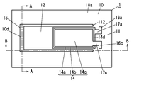
- FIG. 1 is a schematic plan view of a piezoelectric conversion device in Embodiment 1.
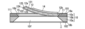
- FIG. 2A is AA schematic sectional drawing of FIG. 2A.
- FIG. 2B is a schematic cross-sectional view taken along the line BB in FIG. 2A. It is principal part sectional drawing of FIG. 2A.
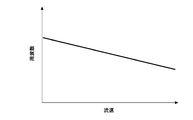
- FIG. 3 is a characteristic explanatory diagram of a flow sensor according to the first embodiment.
- FIG. 3 is a characteristic explanatory diagram of a flow sensor according to the first embodiment.
- FIG. 5 is a schematic plan view of a piezoelectric conversion device in Embodiment 2.
- FIG. 7B is a schematic sectional view taken along line AA in FIG. 7A.
- FIG. 7B is a schematic cross-sectional view taken along line BB in FIG. 7A. It is principal part sectional drawing of FIG. 7A.
- FIG. 6 is a schematic plan view of a piezoelectric conversion device in a fourth embodiment.
- FIG. 9B is a schematic cross-sectional view taken along line AA in FIG. 9A.
- FIG. 9B is a schematic cross-sectional view taken along the line BB of FIG. 9A. It is principal part sectional drawing of FIG. 9A.
- FIG. 6 is a schematic cross-sectional view of a piezoelectric conversion device in Embodiment 5.
- FIG. 10 is another schematic cross-sectional view of the piezoelectric conversion device in Embodiment 5. It is a schematic sectional drawing of the piezoelectric transducer in Embodiment 6. It is another schematic sectional drawing of the piezoelectric transducer in Embodiment 6. It is principal part explanatory drawing of the air-conditioning management system of Embodiment 7.
- FIG. 10 is a schematic configuration diagram of a flow sensor according to a ninth embodiment. It is explanatory drawing which shows typically the electric power generation means in a prior art example. It is explanatory drawing which shows an example of the wind speed dependence of the electromotive force (generated voltage) in a prior art example.
- the flow sensor A ⁇ b> 1 includes a piezoelectric conversion device 1 in which a piezoelectric conversion unit 14 is provided in a cantilever unit 12 that self-excites and receives fluid, and a detection unit 2 that detects an electrical signal output from the piezoelectric conversion unit 14. .
- the piezoelectric conversion device 1 includes a frame-shaped support portion 11, a cantilever portion 12 supported by the support portion 11 so as to be swingable, and a piezoelectric conversion portion 14 provided on the cantilever portion 12.
- the piezoelectric conversion device 1 includes a flow path 15 that is provided between the support portion 11 and the cantilever portion 12 and that allows fluid to pass along the thickness direction of the support portion 11 (vertical direction in FIGS. 2B and 2C). Yes.
- the distal end portion 12 a of the cantilever portion 12 is shifted in a direction away from the support portion 11 with respect to the proximal end portion 12 b of the cantilever portion 12.
- the piezoelectric conversion unit 14 In the piezoelectric conversion device 1, the piezoelectric conversion unit 14 generates an alternating voltage by the self-excited vibration of the cantilever unit 12. The piezoelectric conversion device 1 outputs an electrical signal corresponding to the AC voltage from the piezoelectric conversion unit 14.
- the piezoelectric transducer 1 is manufactured using a manufacturing technology of MEMS (micro-electro-mechanical systems).
- a support portion 11 and a cantilever portion 12 are formed from a substrate 10.
- a cantilever portion 12 is formed as a part of one surface (first surface) 101 of the substrate 10.
- the piezoelectric conversion unit 14 is monolithically formed on the substrate 10.
- an SOI substrate in which a silicon layer 10c is formed on a buried oxide film 10b made of a silicon oxide film on a silicon substrate 10a is used.
- the one surface (first surface) 101 of the substrate 10 is a (100) plane, but is not limited thereto, and may be a (110) plane, for example.
- the support portion 11 is formed of a silicon substrate 10a, a buried oxide film 10b, and a silicon layer 10c among SOI substrates.
- the cantilever part 12 is formed of the buried oxide film 10b and the silicon layer 10c in the SOI substrate, is thinner than the support part 11, and has flexibility.
- the cantilever portion 12 has elasticity.
- the substrate 10 and the piezoelectric conversion unit 14 are electrically insulated by the first insulating film 18 a made of a silicon oxide film formed on the one surface (first surface) 101 side of the substrate 10.
- a second insulating film 18 b made of a silicon oxide film is formed on the other surface (second surface) 102 side of the substrate 10.
- the first insulating film 18a and the second insulating film 18b are formed by a thermal oxidation method.
- the formation method of the first insulating film 18a and the second insulating film 18b is not limited to the thermal oxidation method, and may be a CVD (Chemical Vapor Deposition) method or the like. However, the second insulating film 18b is not necessarily provided.
- the substrate 10 described above is not limited to an SOI substrate, and may be a single crystal silicon substrate, a polycrystalline silicon substrate, a magnesium oxide (MgO) substrate, a metal substrate, a glass substrate, a polymer substrate, or the like.
- MgO magnesium oxide
- a metal substrate a glass substrate
- a polymer substrate or the like.
- the first insulating film 18a and the second insulating film 18b are not necessarily provided.
- the support portion 11 preferably employs a rectangular frame shape as the frame shape.
- a wafer here, an SOI wafer
- a pre-process for forming a large number of piezoelectric transducers 1 from the wafer is performed.
- the workability of the dicing process can be improved.
- the support portion 11 preferably has a rectangular outer peripheral shape, but the inner peripheral shape is not limited to a rectangular shape, and may be, for example, a polygonal shape other than a rectangular shape, a circular shape, an elliptical shape, or the like. Further, the outer peripheral shape of the support portion 11 may be a shape other than a rectangular shape.
- the cantilever part 12 is arranged inside the support part 11 in a plan view.
- the piezoelectric conversion device 1 by forming a U-shaped slit 10 d in a plan view surrounding the cantilever portion 12 in the substrate 10, the portions other than the connection portion with the support portion 11 in the cantilever portion 12 are separated from the support portion 11 and the space. Separated. Thereby, the cantilever part 12 is formed in a rectangular shape in plan view.
- the slit 10 d constitutes the flow path 15.
- the piezoelectric conversion unit 14 is formed on one surface (first surface) 121 side in the thickness direction of the cantilever unit 12 (on the one surface (first surface) 101 side of the substrate 10).
- the piezoelectric conversion unit 14 includes, in order from the cantilever unit 12 side, a first electrode (lower electrode) 14a, a piezoelectric layer (piezoelectric thin film) 14b, and a second electrode (upper electrode) 14c.
- the piezoelectric conversion unit 14 includes a piezoelectric layer 14b and a first electrode 14a and a second electrode 14c facing each other with the piezoelectric layer 14b sandwiched from both sides in the thickness direction.
- the piezoelectric layer 14 b of the piezoelectric conversion unit 14 receives stress due to the vibration of the cantilever unit 12, and a bias of charge occurs between the second electrode 14 c and the first electrode 14 a, and the piezoelectric conversion unit 14. AC voltage is generated at. Therefore, the piezoelectric conversion device 1 can also be used as a vibration type power generation device in which the piezoelectric conversion unit 14 generates power using the piezoelectric effect of the piezoelectric material.
- the planar shape of the piezoelectric layer 14b is formed in a rectangular shape having a slightly smaller planar size than the first electrode 14a and slightly larger than the second electrode 14c.
- the first electrode 14 a, the piezoelectric layer 14 b, and the second electrode 14 c overlap in the direction connecting the support portion 11 and the cantilever portion 12 (the left-right direction in FIGS. 2A and 2C).
- the end 14d of the region on the support portion 11 side is aligned with the boundary 112 between the support portion 11 and the cantilever portion 12.
- the piezoelectric conversion device 1 exists in a portion where the stress is increased when the cantilever 12 is vibrated as compared with the case where the end 14d on the support 11 side of the region is closer to the cantilever 12 than the boundary 112.
- the area of the piezoelectric converter 14 can be increased, and the conversion efficiency can be improved.
- the AC voltage generated in the piezoelectric converter 14 is a sinusoidal AC voltage corresponding to the vibration of the piezoelectric layer 14b.
- an alternating voltage is generated by self-excited vibration generated by fluid flowing through the flow path 15.
- the resonance frequency of the piezoelectric conversion device 1 is determined by the structural parameters and material of the movable part composed of the cantilever part 12 and the piezoelectric conversion part 14. Examples of the fluid flowing through the flow path 15 include air.
- the piezoelectric conversion device 1 includes a first pad 16a electrically connected to the support portion 11 via the first wiring portion 17a and the second electrode 14c via the second wiring portion 17c. Connected second pad 16c.
- the material of the first wiring part 17a, the second wiring part 17c, the first pad 16a and the second pad 16c is Au, but is not limited to this. For example, Mo, Al, Pt, Ir, etc. Good.
- the materials of the first wiring portion 17a, the second wiring portion 17c, the first pad 16a, and the second pad 16c are not limited to the same material, and different materials may be employed.
- the first wiring portion 17a, the second wiring portion 17c, the first pad 16a, and the second pad 16c are not limited to a single layer structure, and may be a multilayer structure having two or more layers.
- the piezoelectric conversion device 1 is provided with an insulating layer (not shown) that prevents a short circuit between the second wiring portion 17c and the first electrode 14a.
- This insulating layer is formed of a silicon oxide film, but is not limited to a silicon oxide film, and may be formed of, for example, a silicon nitride film.
- the piezoelectric conversion device 1 may be provided with an appropriate insulating film depending on the material of the substrate 10.
- the piezoelectric material of the piezoelectric layer 14b PZT (Pb (Zr, Ti) O 3 ) is adopted, but not limited to this, for example, PZT-PMN (Pb (Mn, Nb) O 3 ) and others PZT to which the impurities are added may be used.
- the piezoelectric material is AlN, ZnO, KNN (K 0.5 Na 0.5 NbO 3 ), KN (KNbO 3 ), NN (NaNbO 3 ), KNN, impurities (for example, Li, Nb, Ta, Sb, Cu, etc.). The thing etc. which added may be sufficient.
- the piezoelectric layer 14b is composed of a piezoelectric thin film.
- the material of the first electrode 14a is Pt, but is not limited thereto, and may be Au, Al, Ir or the like, for example. Further, although Au is adopted as the material of the second electrode 14c, it is not limited to this, and for example, Mo, Al, Pt, Ir, or the like may be used.
- the thickness of the first electrode 14 a is set to 500 nm
- the thickness of the piezoelectric layer 14 b is set to 3000 nm
- the thickness of the second electrode 14 c is set to 500 nm. It is not a thing.
- the piezoelectric conversion device 1 may have a structure in which a buffer layer is provided between the substrate 10 and the first electrode 14a.
- the material of the buffer layer may be appropriately selected according to the piezoelectric material of the piezoelectric layer 14b.
- the piezoelectric material of the piezoelectric layer 14b is PZT, for example, SrRuO 3 , (Pb, La) TiO 3 , PbTiO 3 , It is preferable to employ MgO, LaNiO 3 or the like.
- the buffer layer may be constituted by a laminated film of a Pt film and a SrRuO 3 film, for example.
- the piezoelectric conversion device 1 can improve the crystallinity of the piezoelectric layer 14b by providing a buffer layer.
- the configuration of the piezoelectric conversion device 1 is not limited to the above-described example, and for example, the width dimension in the direction along the width direction (vertical direction in FIG. 2A) of the cantilever portion 12 in the piezoelectric conversion portion 14 is reduced to 1
- a plurality of piezoelectric transducers 14 are arranged side by side in the width direction on the one surface (first surface) 121 side of one cantilever portion 12, and one end and the other end of the series circuit of the plurality of piezoelectric transducers 14 are connected to the first pad 16a.
- the second pad 16c may be electrically connected to each other.
- the substrate 10 made of an SOI substrate is prepared, and then an insulating film forming step is performed.
- the first surface made of a silicon oxide film is formed on each of the one surface (first surface) 101 side and the other surface (second surface) 102 side of the substrate 10 by using a thermal oxidation method or the like.
- An insulating film 18a and a second insulating film 18b are formed.
- the thermal oxidation method is adopted as a method of forming the first insulating film 18a and the second insulating film 18b.
- the present invention is not limited to this, and a CVD method or the like may be adopted.
- a first conductive layer serving as a basis for the first electrode 14a and the first wiring portion 17a is formed on the entire surface of the substrate 10 on the one surface (first surface) 101 side.
- a conductive layer forming step is performed, and subsequently, a piezoelectric material layer forming step for forming a piezoelectric material layer serving as a basis of the piezoelectric layer 14b is performed.
- the sputtering method is adopted, but not limited thereto, for example, a CVD method or a vapor deposition method may be adopted.
- the sputtering method is adopted, but not limited thereto, for example, a CVD method or a sol-gel method may be adopted.
- a piezoelectric material layer patterning step for patterning the piezoelectric material layer into a predetermined shape of the piezoelectric layer 14b is performed, and subsequently, the first conductive layer is formed as the first electrode 14a and the first wiring portion 17a.
- a first conductive layer patterning step is performed for patterning into a predetermined shape.
- the piezoelectric material layer patterning step the piezoelectric material layer is patterned using a lithography technique and an etching technique.
- the first conductive layer patterning step the first conductive layer is patterned using a lithography technique and an etching technique.
- an insulating layer forming step for forming the insulating layer on the one surface (first surface) 101 side of the substrate 10 is performed.
- a second conductive layer forming step is performed in which a second conductive layer serving as a basis of the second electrode 14c and the second wiring portion 17c is formed on the entire surface of the substrate 10 on the one surface (first surface) 101 side.
- a second conductive layer patterning step is performed for patterning the second conductive layer into a predetermined shape of the second electrode 14c and the second wiring portion 17c.
- the sputtering method is adopted, but not limited thereto, for example, a CVD method or a vapor deposition method may be adopted.
- the second conductive layer patterning step the second conductive layer is patterned using a lithography technique and an etching technique.
- a third conductive layer serving as a basis for the first pad 16a and the second pad 16c is formed on the entire surface of the substrate 10 on the one surface (first surface) 101 side.
- a third conductive layer forming step is performed, and then a third conductive layer patterning step of patterning the third conductive layer into a predetermined shape of the first pad 16a and the second pad 16c is performed.
- a portion other than the support portion 11 and the cantilever portion 12 (a region where the slit 10 d is to be formed) is etched by an amount corresponding to the thickness of the cantilever portion 12.
- a groove forming step for forming grooves is performed.
- the groove is formed using a lithography technique, an etching technique, and the like.
- the cantilever part 12 is formed together with the support part 11 using a lithography technique and an etching technique.
- Each etching in the groove forming step and the cantilever part forming step is dry etching using an inductively coupled plasma type dry etching apparatus capable of vertical deepening.
- a slit 10d is formed.
- the piezoelectric conversion device 1 includes the flow path 15 provided between the support portion 11 and the cantilever portion 12 and capable of allowing fluid to pass along the thickness direction of the support portion 11 as described above, and the tip of the cantilever portion 12.
- the part 12 a is shifted in a direction away from the support part 11 with respect to the base end part 12 b of the cantilever part 12. That is, the distal end portion 12 a of the cantilever portion 12 is farther from the support portion 11 than the base end portion 12 b of the cantilever portion 12 in the thickness direction of the support portion 11.
- the initial deviation G1 (see FIG. 2B) is preferably 200 ⁇ m or more.
- a deviation in the thickness direction of the support portion 11 of the intersection line 125 between the neutral surface 123 (see FIG. 2C) of the cantilever portion 12 and the front end surface 124 of the cantilever portion 12 is defined as an initial deviation G1.
- the cantilever portion 12 In the initial state where no external vibration or fluid is acting, the cantilever portion 12 is configured such that the distal end portion 12a of the cantilever portion 12 is closer to the support portion 11 than the proximal end portion 12b of the cantilever portion 12 as shown in FIGS. It has been shifted away.
- the cantilever portion 12 is curved so that the one surface (first surface) 121 side is a concave curved surface and the other surface (second surface) 122 side is a convex curved surface.
- the distal end portion 12a of the cantilever portion 12 is shifted away from the support portion 11 relative to the base end portion 12b due to the internal stress of the piezoelectric thin film constituting the piezoelectric layer 14b. That is, the distal end portion 12 a of the cantilever portion 12 is farther from the support portion 11 than the base end portion 12 b in the thickness direction of the support portion 11 due to the internal stress of the piezoelectric thin film constituting the piezoelectric layer 14 b.
- the internal stress of the piezoelectric thin film can be adjusted by appropriately setting process conditions such as gas pressure and temperature.
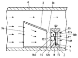
- the direction in which the fluid flows and the thickness direction of the support portion 11 coincide with each other, the one surface (first surface) 101 side of the substrate 10 is the upstream side of the fluid, and the other surface (second surface) of the substrate 10 is. ) It is arranged and used so that the 102 side is the downstream side of the fluid.
- the tip 12a of the cantilever part 12 returns to its original position by the elastic force of the cantilever part 12.
- the cantilever portion 12 self-vibrates by repeating such an operation, so that an AC voltage is generated from the piezoelectric conversion portion 14.
- the piezoelectric conversion device 1 described above includes the flow path 15 that is provided between the support portion 11 and the cantilever portion 12 and allows fluid to pass along the thickness direction of the support portion 11. Further, in the piezoelectric conversion device 1, the distal end portion 12 a of the cantilever portion 12 is shifted in a direction away from the support portion 11 with respect to the proximal end portion 12 b of the cantilever portion 12. That is, the distal end portion 12 a of the cantilever portion 12 is farther from the support portion 11 than the base end portion 12 b of the cantilever portion 12 in the thickness direction of the support portion 11.
- the piezoelectric transducer 1 is configured such that the pressure on the one surface (first surface) 121 side and the other surface (second surface) 122 side of the cantilever portion 12 generated by the flow of fluid (airflow) through the flow path 15. Since the self-excited vibration can be generated by the difference and the elasticity of the cantilever portion 12, it is possible to generate an alternating voltage whose absolute value of the peak voltage changes according to the flow velocity and flow rate of the fluid.
- the fluid passing through the flow path 15 is not limited to air, but may be, for example, gas, a mixed gas of air and gas, or liquid.
- Examples of the electrical signal detected by the detection unit 2 include a peak value and a frequency of an AC voltage generated by the piezoelectric conversion unit 14.
- the detection unit 2 is configured by, for example, a peak hold circuit (peak voltage detection circuit) that detects the absolute value of the peak voltage of the AC voltage output from the piezoelectric conversion unit 14 and a control circuit that controls the peak hold circuit.
- the peak hold circuit can include a rectifier circuit, a capacitor that holds the maximum value of the output of the rectifier circuit, a reset circuit that discharges the charge held by the capacitor, a control unit that controls the reset circuit, and the like.
- the detection unit 2 can intermittently detect the absolute value of the peak voltage of the AC voltage generated in the piezoelectric conversion unit 14.
- the detection unit 2 includes, for example, a control unit configured by a microcomputer equipped with an appropriate program, and the control unit corresponds in advance to the absolute value of the AC voltage generated by the piezoelectric conversion unit 14 and the flow velocity. You may make it provide the memory which memorize
- FIG. 3 shows a correlation example (correlation) between the generated voltage composed of the absolute value of the peak value of the AC voltage and the flow velocity.
- correlation examples F1, F2, and F3 of the three types of piezoelectric transducers 1 are shown.
- the length of the cantilever portion 12 is the same, and the width of the cantilever portion 12 is different.
- the correlation example F1 has a small width dimension of the cantilever part 12
- the correlation example F3 has a large width dimension of the cantilever part 12
- the correlation example F2 has a width dimension of the cantilever part 12.
- This is an example in the middle of the width dimension of the cantilever part 12 having the characteristics of F1 and the width dimension of the cantilever part 12 having the characteristics of the correlation example F3.
- the piezoelectric transducer 1 if the width dimension of the cantilever portion 12 is increased, the flow velocity at which self-excited vibration starts increases, but the generated voltage tends to increase gradually as the flow velocity increases. Therefore, it can be used for the flow sensor A1 that detects the flow velocity in a relatively wide flow velocity region.
- the piezoelectric transducer 1 is relatively narrow because the flow velocity at which self-excited vibration starts decreases and the generated voltage tends to increase sharply as the flow velocity increases. It can be used for the flow sensor A1 that detects the flow velocity in the flow velocity region.
- the piezoelectric conversion device 1 is considered to be suitable for power generation when it is desired to maintain a stable generated voltage because the flow velocity at which the generated voltage is saturated is relatively low.
- the frequency of the AC voltage generated in the piezoelectric transducer 14 decreases as the fluid flow rate increases. This is presumed that in the piezoelectric transducer 1, when the fluid flow rate increases, the pressure on the one surface (first surface) 121 of the cantilever portion 12 increases, and therefore the frequency decreases. The relationship between the flow velocity and the frequency is almost linear.
- the frequency of the AC voltage generated in the piezoelectric conversion unit 14 can be detected by, for example, a voltage-frequency conversion circuit.
- the detection unit 2 includes a memory in which the above-described control unit stores a table (for example, data in FIG. 4) in which the frequency of the AC voltage generated by the piezoelectric conversion unit 14 and the flow velocity are associated in advance. May be.
- the flow sensor A1 described above includes a piezoelectric conversion device 1 in which a piezoelectric conversion unit 14 is provided in a cantilever unit 12 that receives a fluid and self-excites, and a detection unit 2 that detects an electrical signal output from the piezoelectric conversion unit 14. And.
- this flow sensor A1 since it is not necessary to supply electric power to the piezoelectric conversion unit 14 for sensing fluid, lower power consumption is achieved compared to the thermal flow sensor described in Document 1 described in the background art. It becomes possible.
- the flow sensor A1 since the flow sensor A1 includes the piezoelectric conversion device 1 in which the piezoelectric conversion unit 14 is provided in the cantilever unit 12 that receives the fluid and self-excites, the power generation described in Reference 2 described in the background art. It is possible to reduce the size as compared with the means. As a result, the flow sensor A1 can be reduced in power consumption and size. In addition, the flow sensor A1 can reduce the frequency and cost of maintenance by reducing power consumption.
- the piezoelectric conversion device 1 includes a frame-shaped support portion 11, a cantilever portion 12 that is swingably supported by the support portion 11, a piezoelectric conversion portion 14 provided on the cantilever portion 12, and a support portion 11.
- a flow path 15 provided between the cantilever part 12 and a fluid through which the fluid can pass along the thickness direction of the support part 11.
- the tip part 12a of the cantilever part 12 is supported more than the base end part 12b of the cantilever part 12. It is preferable to be shifted away from the part 11. That is, it is preferable that the distal end portion 12 a of the cantilever portion 12 is farther from the support portion 11 than the base end portion 12 b of the cantilever portion 12 in the thickness direction of the support portion 11.
- the flow sensor A1 converts the energy of the fluid passing through the flow path 15 provided between the support portion 11 and the cantilever portion 12 into vibration energy of the cantilever portion 12 with high efficiency. It becomes possible. Therefore, the flow sensor A1 can improve the detection accuracy of the fluid flow velocity and flow rate.
- the piezoelectric conversion unit 14 includes a first electrode 14a and a piezoelectric layer (piezoelectric thin film) in order from the one surface (first surface) 121 side on the one surface (first surface) 121 side in the thickness direction of the cantilever portion 12. ) 14b and the second electrode 14c, and the distal end portion 12a of the cantilever portion 12 is shifted away from the support portion 11 with respect to the base end portion 12b by the internal stress of the piezoelectric layer (piezoelectric thin film) 14b.
- the flow sensor A1 can efficiently generate energy of the fluid passing through the flow path 15 provided between the support portion 11 and the cantilever portion 12 without increasing the components of the piezoelectric conversion device 1. It is possible to convert it into 12 vibration energies.
- the flow sensor A ⁇ b> 1 may be configured to include a wireless transmission unit 6 that intermittently transmits a wireless signal including the detection result of the detection unit 2.
- the flow sensor A1 can intermittently transmit a radio signal including the detection result of the detection unit 2 to the outside. Therefore, the flow sensor A1 can be easily constructed, has a high degree of freedom in installation location, and can improve versatility. Moreover, it becomes possible to investigate the distribution of the air flow state by appropriately arranging a plurality of flow sensors A1.
- EnOcean registered trademark
- the flow sensor A ⁇ b> 1 may be configured to include a power storage unit 5 that rectifies and stores an AC voltage generated in the piezoelectric conversion device 1, and a switching circuit 9.
- the switching circuit 9 can switch between a first state in which the piezoelectric conversion unit 14 and the power storage unit 5 are electrically connected and a second state in which the piezoelectric conversion unit 14 and the detection unit 2 are electrically connected.
- the piezoelectric conversion unit 14 includes a first state in which the piezoelectric conversion unit 14 and the power storage unit 5 are electrically connected, and a second state in which the piezoelectric conversion unit 14 and the detection unit 2 are electrically connected. Is connected to a switching circuit 9 for switching between.
- the detection unit 2 and the wireless transmission unit 6 can operate using the power storage unit 5 as a power source.
- the flow sensor A1 includes a switching element 8 provided in a power supply path from the power storage unit 5 to the detection unit 2 and the wireless transmission unit 6, and a power storage amount monitoring unit 7 that monitors the power storage amount of the power storage unit 5.
- the switching element 8 can be composed of, for example, a MOSFET.
- the power storage amount monitoring unit 7 has a function of monitoring the voltage between the output terminals of the power storage unit 5 as the power storage amount, and turning on and off the switching element 8 based on a comparison result between the power storage amount and a preset specified value. .
- the electricity storage amount monitoring unit 7 turns on the switching element 8 and turns on the electricity storage unit 5.
- the switching element 8 is turned off. Thereby, the detection unit 2 and the wireless transmission unit 6 are intermittently supplied with power from the power storage unit 5 and driven.
- the switching circuit 9 may be configured such that, for example, the storage amount monitoring unit 7 controls on / off.
- the power storage amount monitoring unit 7 may switch the switching circuit 9 from the first state to the second state when the power storage amount of the power storage unit 5 reaches the specified value.
- the flow sensor A1 includes the switching circuit 9, it is possible to shorten the time until the amount of power stored in the power storage unit 5 reaches the specified value every time the power storage unit 5 is charged.
- the power storage unit 5 can be composed of, for example, a full-wave rectifier circuit including a diode bridge that rectifies an AC voltage generated in the piezoelectric conversion device 1 and a capacitor connected between the output terminals of the full-wave rectifier circuit.
- the flow sensor A1 connects one output end of the piezoelectric transducer 1 to one input end of the full-wave rectifier circuit, and connects the other output end of the piezoelectric transducer 1 to the other end of the full-wave rectifier circuit. What is necessary is just to connect the detection part 2 and the radio
- the power storage unit 5 can be constituted by, for example, a double wave voltage doubler rectifier circuit.
- the double voltage rectifier circuit a series circuit of two diodes and a series circuit of two capacitors are connected in parallel.
- two diodes and two capacitors are bridge-connected.
- the flow sensor A1 connects one output terminal of the piezoelectric conversion device 1 to a connection point of both diodes in a series circuit of two diodes.
- the other output terminal may be connected to the connection point of both capacitors in a series circuit of two capacitors.
- the flow sensor A1 should just connect the detection part 2 and the wireless transmission part 6 between the both ends of the series circuit of two capacitors.
- FIG. 6 is a schematic configuration diagram of an air conditioning management system using the above-described flow sensor A1.
- This air conditioning management system includes a flow sensor A1 and an air conditioner (air conditioner) A2.
- the flow sensor A1 is disposed inside an air supply duct (not shown) or an exhaust duct (not shown) of the air conditioner A2.
- the air conditioner A2 includes a wireless reception unit 71 that receives a wireless signal from the wireless transmission unit 6, and based on the wireless signal received by the wireless reception unit 71, the flow rate or flow velocity of the fluid of the fan 74 is set to a target value. Control the operating state. Accordingly, the air conditioning management system can be used as an air conditioning management system including the flow sensor A1 that can reduce power consumption and size.
- the air conditioner A2 includes a motor 73 that rotates the fan 74, an operation switch 75, a control unit 72 that controls the motor 73, and a setting unit that sets target values for flow rate and flow velocity based on a remote control signal from a remote controller. 76.
- the control unit 72 drives the motor 73 to rotate the fan 74.
- the control unit 72 feedback-controls the rotation speed of the motor 73 so that the flow rate or the flow velocity target value set by the setting unit 76 is obtained.
- the control unit 72 may be configured to include, for example, a control circuit composed of a microcomputer or the like on which an appropriate program is installed, a drive circuit that drives the motor 73, and the like.
- the piezoelectric conversion device 1 includes a tip end portion of the cantilever portion 12 by the stress control film 19 (see FIG. 7C) provided on the one surface (first surface) 121 side of the cantilever portion 12. 12a is shifted in the direction away from the support part 11 rather than the base end part 12b. That is, due to the stress control film 19, the distal end portion 12 a of the cantilever portion 12 is further away from the support portion 11 than the base end portion 12 b in the thickness direction of the support portion 11.
- symbol is attached
- the stress control film 19 is formed on the opposite side of the second electrode 14c from the piezoelectric layer 14b side.
- the stress control film 19 is composed of a SiO 2 film, but is not limited thereto, and may be composed of, for example, a Si 3 N 4 film.
- the stress control film 19 may be formed on the other surface (second surface) 122 side of the cantilever portion 12. Further, the stress control film 19 may be formed on the entire surface of the one surface (first surface) 121 or the other surface (second surface) 122 of the cantilever portion 12 or may be formed on a part thereof.
- the piezoelectric conversion device 1 has the one surface (first surface) 121 side and the other surface (second surface) 122 of the cantilever portion 12 generated by the flow of fluid through the flow path 15.
- a self-excited vibration can be generated by the pressure difference from the side and the elasticity of the cantilever portion 12, and an alternating voltage can be generated.
- the piezoelectric conversion device 1 in the present embodiment has a higher degree of freedom in the process conditions of the piezoelectric layer 14b than in the first embodiment, and can form a higher quality piezoelectric layer 14b, resulting in energy conversion efficiency. It is possible to improve.
- the piezoelectric conversion device 1 causes the distal end portion 12a of the cantilever portion 12 to be moved to the proximal end by the stress acting on the cantilever portion 12 due to the stress control film 19 and the internal stress of the piezoelectric layer 14b that is a piezoelectric thin film. You may shift to the direction which leaves
- the piezoelectric conversion device 1 supports the distal end portion 12a of the cantilever portion 12 more than the proximal end portion 12b by disposing the cantilever portion 12 with respect to the support portion 11. It is shifted in a direction away from the part 11. That is, by disposing the cantilever portion 12 with respect to the support portion 11, the distal end portion 12 a of the cantilever portion 12 is farther from the support portion 11 than the base end portion 12 b in the thickness direction of the support portion 11.
- the cantilever part 12 is inclined with respect to one surface (first surface, upper surface in FIG. 8) 111 of the support part 11 orthogonal to the thickness direction of the support part 11.
- symbol is attached
- the piezoelectric transducer 1 in this embodiment is a bulk type piezoelectric transducer.
- the piezoelectric conversion device 1 according to the present embodiment uses a bulk as the piezoelectric layer 14b, and the first electrode 14a made of a metal film is formed on the other surface (second surface) 1402 side in the thickness direction of the piezoelectric layer 14b.
- the beam member 20 in which the second electrode 14 c made of a metal film is formed on one surface (first surface) 1401 side is inclined with respect to the support portion 11.
- the beam member 20 may be fixed to the mounting base portion 21 provided on the one surface (first surface) 111 of the support portion 11 with, for example, an adhesive.
- the mounting base 21 has an inclined surface 21a for inclining and arranging the beam member 20 at a desired angle. That is, the mounting base portion 21 is disposed by tilting the piezoelectric conversion portion 14 at a desired angle. Thereby, the front-end
- the piezoelectric layer 14 b also serves as the cantilever part 12, so that the piezoelectric conversion part 14 is provided in the cantilever part 12.
- the mount 21 may be fixed to the support 11 with, for example, an adhesive.
- the support portion 11 may be formed by machining a metal plate, or may be formed of a resin molded product, and the substrate 10 may be formed using a MEMS manufacturing technique or the like as in the first embodiment. It may be formed by processing.
- the piezoelectric conversion device 1 has the one surface (first surface) 121 side and the other surface (second surface) 122 of the cantilever portion 12 generated by the flow of fluid through the flow path 15. Since the self-excited vibration can be generated by the pressure difference from the side and the elasticity of the cantilever part 12, an AC voltage corresponding to the flow rate and flow rate of the fluid can be generated.
- the piezoelectric conversion device 1 according to the present embodiment is different from the piezoelectric conversion device 1 according to the first embodiment in the shape of the inner surface of the support portion 11.
- symbol is attached
- the support part 11 of the piezoelectric conversion device 1 in this embodiment is formed in a shape in which the cross-sectional area of the flow path 15 is wider on both sides in the thickness direction of the support part 11 than in the middle of the thickness direction.
- the piezoelectric conversion device 1 is the manufacturing method described in the first embodiment, in which the etching in the groove forming step and the cantilever portion forming step is anisotropic etching with an alkaline solution, so that the support portion 11 described above is used.
- the shape of the flow path 15 can be realized.
- the support portion 11 has a shape in which the cross-sectional area of the flow channel 15 is wider on both sides in the thickness direction of the support portion 11 than in the middle of the thickness direction. It is possible to increase the flow rate of the fluid passing therethrough. Therefore, the piezoelectric transducer 1 increases the pressure difference between the one surface (first surface) 121 side and the other surface (second surface) 122 side of the cantilever portion 12 generated when the fluid passes through the flow path 15. And energy conversion efficiency can be improved.
- the piezoelectric conversion device 1 houses a piezoelectric conversion element 1a including a support part 11, a cantilever part 12, a piezoelectric conversion part 14, and a flow path 15, and a piezoelectric conversion element 1a.
- Storage member 1b the same code
- the configuration of the piezoelectric conversion element 1a is the same as that of the piezoelectric conversion device 1 in the first embodiment, the same components as those in the first embodiment are denoted by the same reference numerals and description thereof is omitted.
- the piezoelectric transducer 1a is not limited to the piezoelectric transducer 1 in the first embodiment, and may have the same configuration as the piezoelectric transducer 1 in any of the second to fourth embodiments.
- the storage member 1b is provided with an inlet 1ba through which a fluid flows in and an outlet 1bb through which the fluid flows out, and a piezoelectric conversion element 1a is disposed between the inlet 1ba and the outlet 1bb.
- the arrow in FIG. 10A, 10B has shown typically the direction through which a fluid flows.
- the housing member 1b has a shape in which the opening area decreases as it approaches the piezoelectric conversion element 1a from the inlet 1ba, and the opening area increases as it approaches the outlet 1bb from the piezoelectric conversion element 1a.
- the storage member 1b holds the peripheral portion of the support portion 11 of the piezoelectric conversion element 1a.
- the storage member 1b has a rectangular outer peripheral shape and a rectangular opening shape. For example, if such a storage member 1b is formed by joining two half-square cylindrical members, the piezoelectric conversion element 1a can be easily stored and held.
- the storage member 1b may be formed using a three-dimensional circuit forming substrate.
- the storage member 1b includes the power storage unit 5, the switching circuit 9, the detection unit 2, and the wireless transmission unit described with reference to FIG. 6, a storage amount monitoring unit 7 and a switching element 8 may be provided.
- the piezoelectric conversion device 1 includes the storage member 1b that stores the piezoelectric conversion element 1a. As the storage member 1b approaches the piezoelectric conversion element 1a from the inlet 1ba, the opening area decreases, and the piezoelectric conversion element 1a. Is formed in a shape in which the opening area increases as it approaches the outlet 1bb. As a result, the piezoelectric conversion device 1 can increase the flow rate of the fluid passing through the flow path 15. Therefore, the piezoelectric transducer 1 increases the pressure difference between the one surface (first surface) 121 side and the other surface (second surface) 122 side of the cantilever portion 12 generated when the fluid passes through the flow path 15. And energy conversion efficiency can be improved. In addition, since the piezoelectric conversion device 1 includes the storage member 1b, the piezoelectric conversion element 1a can be protected by the storage member 1b, and there is an advantage that handling is facilitated.
- the storage member 1b is formed in a drum shape with both surfaces open, and compared with the fifth embodiment, the piezoelectric conversion element 1a.
- the opening area of each of the inflow port 1ba and the outflow port 1bb of the storage member 1b is increased without changing the plane size.
- the piezoelectric transducer 1 can increase the flow rate of the fluid passing through the flow path 15. Therefore, the piezoelectric transducer 1 further increases the pressure difference between the one surface (first surface) 121 side and the other surface (second surface) 122 side of the cantilever portion 12 generated by the fluid passing through the flow path 15. This makes it possible to further improve the energy conversion efficiency.
- the air-conditioning management system of this embodiment is provided with a fluid control unit 3 arranged in a duct 4 consisting of either an air supply duct or an exhaust duct. Differs from the management system.
- the fluid control unit 3 can control the flow of the fluid so as to increase the flow rate of the fluid passing through the flow path 15 of the piezoelectric transducer 1.
- the arrow in FIG. 12 has shown typically the direction through which the fluid flows.
- the configuration of the piezoelectric transducer 1 is the same as that of the piezoelectric transducer 1 in the fifth embodiment, but is not limited to this, and may be the same as that of the piezoelectric transducer 1 in any of the first to fourth embodiments.
- the air conditioning management system may include a plurality of flow sensors A1.
- the fluid control unit 3 and the piezoelectric transducer 1 are arranged side by side along the direction of fluid flow in the duct 4.
- the fluid control unit 3 is disposed on the upstream side
- the piezoelectric conversion device 1 is disposed on the downstream side.
- the fluid control unit 3 includes a nozzle, and is arranged so that the side near the piezoelectric conversion device 1 is the air outlet 3b and the side far from the piezoelectric conversion device 1 is the suction port 3a.
- the air conditioning management system includes a fluid control unit 3 provided outside the piezoelectric conversion device 1 and capable of controlling the flow of fluid so as to increase the flow rate of the fluid passing through the flow path 15.
- the flow rate of the fluid passing through the flow path 15 can be further increased. Therefore, in the air conditioning management system, the pressure on the one surface (first surface) 121 side and the other surface (second surface) 122 side of the cantilever portion 12 generated when the fluid passes through the flow path 15 of the piezoelectric transducer 1.
- the difference can be further increased, and the energy conversion efficiency in the piezoelectric conversion device 1 can be further improved. Thereby, the air-conditioning management system can shorten the pause period of the detection unit 2 and the wireless transmission unit 6 that operate intermittently.
- the fluid control unit 3 has a cylindrical shape, but is not limited thereto, and may be, for example, a triangular prism shape or a spherical shape.
- the air conditioning management system includes the fluid control unit 3 that is provided outside the piezoelectric transducer 1 and that can control the flow of the fluid so as to increase the flow rate of the fluid that passes through the flow path 15. ing. Therefore, the air conditioning management system can further increase the flow rate of the fluid passing through the flow path 15 of the piezoelectric conversion device 1. Therefore, in the flow sensor A1, the pressure on the one surface (first surface) 121 side and the other surface (second surface) 122 side of the cantilever portion 12 generated when the fluid passes through the flow path 15 of the piezoelectric conversion device 1. The difference can be further increased, and the energy conversion efficiency can be further improved. Thereby, the air-conditioning management system can shorten the pause period of the detection unit 2 and the wireless transmission unit 6 that operate intermittently.
- the flow sensor A1 of the present embodiment has substantially the same configuration as that of the first embodiment, and the piezoelectric conversion device 1 is connected to the first piezoelectric conversion unit 141 connected to the power storage unit 5 and the detection unit 2 as the piezoelectric conversion unit 14. A difference is that the second piezoelectric conversion unit 142 is connected.
- symbol same as Embodiment 1 is attached
- subjected and description is abbreviate
- the configuration of the piezoelectric transducer 1 is the same as that of the piezoelectric transducer 1 described in the first embodiment, for example, with the width dimension in the direction along the width direction (vertical direction in FIG. 2A) of the cantilever portion 12 in the piezoelectric transducer 14.
- the two piezoelectric transducers 14 may be arranged side by side in the width direction on the one surface (first surface) 121 side of one cantilever portion 12.
- one piezoelectric conversion unit 14 is used as the first piezoelectric conversion unit 141, and the other piezoelectric conversion unit 14 is used as the second piezoelectric conversion unit 142, and two pads for taking out the output of the first piezoelectric conversion unit 141 and Two pads for taking out the output of the second piezoelectric conversion unit 142 may be provided.
- the piezoelectric conversion device 1 includes, as the piezoelectric conversion unit 14, a first piezoelectric conversion unit 141 connected to the power storage unit 5, and a second piezoelectric conversion unit 142 connected to the detection unit 2. Therefore, the electric signal output from the piezoelectric conversion unit 14 can be detected with a simple circuit configuration.
- a configuration including two piezoelectric conversion units 14 may be employed in the flow sensor A1 of the first to eighth embodiments. You may use flow sensor A1 of this embodiment for the air-conditioning management system demonstrated in Embodiment 1. FIG.
- the number of piezoelectric conversion units 14 is not limited to two, but may be three or more, and it is sufficient that at least one first piezoelectric conversion unit 141 and one second piezoelectric conversion unit 142 are provided.
- the flow sensor A1 may have a configuration in which two piezoelectric conversion devices 1 each including only one piezoelectric conversion unit 14 are provided side by side.
Landscapes
- Engineering & Computer Science (AREA)
- Physics & Mathematics (AREA)
- General Physics & Mathematics (AREA)
- Fluid Mechanics (AREA)
- Chemical & Material Sciences (AREA)
- Combustion & Propulsion (AREA)
- Mechanical Engineering (AREA)
- General Engineering & Computer Science (AREA)
- Aviation & Aerospace Engineering (AREA)
- General Electrical Machinery Utilizing Piezoelectricity, Electrostriction Or Magnetostriction (AREA)
Abstract
La présente invention concerne un débitmètre comprenant un transducteur piézoélectrique pourvu d'une pièce de transduction piézoélectrique dans une partie de cantilever auto-oscillant qui reçoit un fluide, et un détecteur pour détecter un signal électrique produit par la pièce de transduction piézoélectrique.
Applications Claiming Priority (2)
| Application Number | Priority Date | Filing Date | Title |
|---|---|---|---|
| JP2012-163843 | 2012-07-24 | ||
| JP2012163843 | 2012-07-24 |
Publications (1)
| Publication Number | Publication Date |
|---|---|
| WO2014016985A1 true WO2014016985A1 (fr) | 2014-01-30 |
Family
ID=49996814
Family Applications (1)
| Application Number | Title | Priority Date | Filing Date |
|---|---|---|---|
| PCT/JP2013/001512 Ceased WO2014016985A1 (fr) | 2012-07-24 | 2013-03-08 | Débitmètre et systèmes de gestion de conditionnement d'air l'utilisant |
Country Status (2)
| Country | Link |
|---|---|
| TW (1) | TW201405103A (fr) |
| WO (1) | WO2014016985A1 (fr) |
Cited By (2)
| Publication number | Priority date | Publication date | Assignee | Title |
|---|---|---|---|---|
| JP2019141117A (ja) * | 2018-02-15 | 2019-08-29 | 国立大学法人 東京大学 | 脈波センサ |
| CN114812915A (zh) * | 2022-06-24 | 2022-07-29 | 中国空气动力研究与发展中心低速空气动力研究所 | 一种压力扫描阀电路 |
Families Citing this family (2)
| Publication number | Priority date | Publication date | Assignee | Title |
|---|---|---|---|---|
| JP6674424B2 (ja) * | 2017-09-25 | 2020-04-01 | Ckd株式会社 | 渦流量計 |
| TWI764654B (zh) * | 2021-03-30 | 2022-05-11 | 明泰科技股份有限公司 | 用以檢測出風路徑暢通或阻塞的風量檢測裝置 |
Citations (9)
| Publication number | Priority date | Publication date | Assignee | Title |
|---|---|---|---|---|
| JPS516976U (fr) * | 1974-07-02 | 1976-01-19 | ||
| JPS5714727U (fr) * | 1980-06-27 | 1982-01-26 | ||
| JPS6256820A (ja) * | 1985-09-06 | 1987-03-12 | Shinmeguro Keiki Kk | 流量計測用絞り装置 |
| JPH0333373U (fr) * | 1989-08-08 | 1991-04-02 | ||
| JPH05333037A (ja) * | 1992-05-27 | 1993-12-17 | Aichi Tokei Denki Co Ltd | フローセンサ |
| JPH07103996A (ja) * | 1993-10-06 | 1995-04-21 | Oki Electric Ind Co Ltd | ガスフローセンサ及びその形成方法 |
| JP2007298263A (ja) * | 2006-04-28 | 2007-11-15 | Kyodo-Allied Industries Ltd | ファンフィルターユニットを用いて換気設備における空気特性を維持するための方法および装置 |
| JP2011233108A (ja) * | 2010-04-30 | 2011-11-17 | Toshiba Corp | 監視システム及び監視方法 |
| JP2012085456A (ja) * | 2010-10-13 | 2012-04-26 | Seiko Epson Corp | 圧電型発電機とその製造方法、およびセンサーノード |
-
2013
- 2013-03-08 TW TW102108281A patent/TW201405103A/zh unknown
- 2013-03-08 WO PCT/JP2013/001512 patent/WO2014016985A1/fr not_active Ceased
Patent Citations (9)
| Publication number | Priority date | Publication date | Assignee | Title |
|---|---|---|---|---|
| JPS516976U (fr) * | 1974-07-02 | 1976-01-19 | ||
| JPS5714727U (fr) * | 1980-06-27 | 1982-01-26 | ||
| JPS6256820A (ja) * | 1985-09-06 | 1987-03-12 | Shinmeguro Keiki Kk | 流量計測用絞り装置 |
| JPH0333373U (fr) * | 1989-08-08 | 1991-04-02 | ||
| JPH05333037A (ja) * | 1992-05-27 | 1993-12-17 | Aichi Tokei Denki Co Ltd | フローセンサ |
| JPH07103996A (ja) * | 1993-10-06 | 1995-04-21 | Oki Electric Ind Co Ltd | ガスフローセンサ及びその形成方法 |
| JP2007298263A (ja) * | 2006-04-28 | 2007-11-15 | Kyodo-Allied Industries Ltd | ファンフィルターユニットを用いて換気設備における空気特性を維持するための方法および装置 |
| JP2011233108A (ja) * | 2010-04-30 | 2011-11-17 | Toshiba Corp | 監視システム及び監視方法 |
| JP2012085456A (ja) * | 2010-10-13 | 2012-04-26 | Seiko Epson Corp | 圧電型発電機とその製造方法、およびセンサーノード |
Cited By (4)
| Publication number | Priority date | Publication date | Assignee | Title |
|---|---|---|---|---|
| JP2019141117A (ja) * | 2018-02-15 | 2019-08-29 | 国立大学法人 東京大学 | 脈波センサ |
| JP7113487B2 (ja) | 2018-02-15 | 2022-08-05 | 国立大学法人 東京大学 | 脈波センサ |
| CN114812915A (zh) * | 2022-06-24 | 2022-07-29 | 中国空气动力研究与发展中心低速空气动力研究所 | 一种压力扫描阀电路 |
| CN114812915B (zh) * | 2022-06-24 | 2022-10-18 | 中国空气动力研究与发展中心低速空气动力研究所 | 一种压力扫描阀电路 |
Also Published As
| Publication number | Publication date |
|---|---|
| TW201405103A (zh) | 2014-02-01 |
Similar Documents
| Publication | Publication Date | Title |
|---|---|---|
| US11800294B2 (en) | MEMS transducer with improved performance | |
| WO2014141336A1 (fr) | Convertisseur piézoélectrique et capteur de débit l'utilisant | |
| US12058939B2 (en) | Piezoelectric MEMS microphone | |
| US20120240672A1 (en) | Miniaturized energy generation system | |
| JP5707323B2 (ja) | 圧電型memsマイクロフォン | |
| US7687977B2 (en) | Micromachined, piezoelectric vibration-induced energy harvesting device and its fabrication | |
| US8633634B2 (en) | MEMs-based cantilever energy harvester | |
| JP2016086599A (ja) | 発電装置 | |
| US20130127295A1 (en) | Piezoelectric micro power generator and fabrication method thereof | |
| WO2015112452A1 (fr) | Transducteurs piézoélectriques arrondis | |
| Park et al. | Micro-fabricated lead zirconate titanate bent cantilever energy harvester with multi-dimensional operation | |
| WO2014016985A1 (fr) | Débitmètre et systèmes de gestion de conditionnement d'air l'utilisant | |
| WO2014013638A1 (fr) | Module de production de puissance et système de commande de climatisation utilisant ce module | |
| Yao et al. | Compact piezoelectric stacked actuators for high power applications | |
| US20020175596A1 (en) | Thin profile piezoelectric jet device | |
| Wang et al. | Highly sensitive piezoelectric micromachined ultrasonic transducer operated in air | |
| WO2014188649A1 (fr) | Appareil générateur d'énergie | |
| Wang et al. | Highly sensitive piezoelectric micromachined ultrasonic transducer (pMUT) operated in air | |
| WO2013186965A1 (fr) | Appareil de génération de puissance et module de génération de puissance | |
| Aktakka et al. | High stroke and high deflection bulk-PZT diaphragm and cantilever micro actuators and effect of pre-stress on device performance | |
| WO2013190744A1 (fr) | Générateur de vibrations | |
| US20130020910A1 (en) | Vibration power generation device and method of making the same | |
| JP2015161229A (ja) | 発電装置 | |
| JP2015094229A (ja) | 流体振動発電装置 | |
| Polla | Application of PZT thin films in microelectromechanical systems |
Legal Events
| Date | Code | Title | Description |
|---|---|---|---|
| 121 | Ep: the epo has been informed by wipo that ep was designated in this application |
Ref document number: 13822392 Country of ref document: EP Kind code of ref document: A1 |
|
| NENP | Non-entry into the national phase |
Ref country code: DE |
|
| 122 | Ep: pct application non-entry in european phase |
Ref document number: 13822392 Country of ref document: EP Kind code of ref document: A1 |
|
| NENP | Non-entry into the national phase |
Ref country code: JP |