WO2014017158A1 - Procédé de fabrication d'essieu arrière, et essieu arrière - Google Patents
Procédé de fabrication d'essieu arrière, et essieu arrière Download PDFInfo
- Publication number
- WO2014017158A1 WO2014017158A1 PCT/JP2013/064478 JP2013064478W WO2014017158A1 WO 2014017158 A1 WO2014017158 A1 WO 2014017158A1 JP 2013064478 W JP2013064478 W JP 2013064478W WO 2014017158 A1 WO2014017158 A1 WO 2014017158A1
- Authority
- WO
- WIPO (PCT)
- Prior art keywords
- rear axle
- brake flange
- welding
- axle housing
- press
- Prior art date
- Legal status (The legal status is an assumption and is not a legal conclusion. Google has not performed a legal analysis and makes no representation as to the accuracy of the status listed.)
- Ceased
Links
Images




Classifications
-
- B—PERFORMING OPERATIONS; TRANSPORTING
- B60—VEHICLES IN GENERAL
- B60B—VEHICLE WHEELS; CASTORS; AXLES FOR WHEELS OR CASTORS; INCREASING WHEEL ADHESION
- B60B35/00—Axle units; Parts thereof ; Arrangements for lubrication of axles
- B60B35/12—Torque-transmitting axles
-
- B—PERFORMING OPERATIONS; TRANSPORTING
- B60—VEHICLES IN GENERAL
- B60B—VEHICLE WHEELS; CASTORS; AXLES FOR WHEELS OR CASTORS; INCREASING WHEEL ADHESION
- B60B35/00—Axle units; Parts thereof ; Arrangements for lubrication of axles
- B60B35/12—Torque-transmitting axles
- B60B35/14—Torque-transmitting axles composite or split, e.g. half- axles; Couplings between axle parts or sections
-
- B—PERFORMING OPERATIONS; TRANSPORTING
- B23—MACHINE TOOLS; METAL-WORKING NOT OTHERWISE PROVIDED FOR
- B23K—SOLDERING OR UNSOLDERING; WELDING; CLADDING OR PLATING BY SOLDERING OR WELDING; CUTTING BY APPLYING HEAT LOCALLY, e.g. FLAME CUTTING; WORKING BY LASER BEAM
- B23K31/00—Processes relevant to this subclass, specially adapted for particular articles or purposes, but not covered by any single one of main groups B23K1/00 - B23K28/00
- B23K31/02—Processes relevant to this subclass, specially adapted for particular articles or purposes, but not covered by any single one of main groups B23K1/00 - B23K28/00 relating to soldering or welding
-
- B—PERFORMING OPERATIONS; TRANSPORTING
- B23—MACHINE TOOLS; METAL-WORKING NOT OTHERWISE PROVIDED FOR
- B23K—SOLDERING OR UNSOLDERING; WELDING; CLADDING OR PLATING BY SOLDERING OR WELDING; CUTTING BY APPLYING HEAT LOCALLY, e.g. FLAME CUTTING; WORKING BY LASER BEAM
- B23K9/00—Arc welding or cutting
- B23K9/02—Seam welding; Backing means; Inserts
- B23K9/028—Seam welding; Backing means; Inserts for curved planar seams
-
- B—PERFORMING OPERATIONS; TRANSPORTING
- B60—VEHICLES IN GENERAL
- B60B—VEHICLE WHEELS; CASTORS; AXLES FOR WHEELS OR CASTORS; INCREASING WHEEL ADHESION
- B60B35/00—Axle units; Parts thereof ; Arrangements for lubrication of axles
- B60B35/02—Dead axles, i.e. not transmitting torque
- B60B35/04—Dead axles, i.e. not transmitting torque straight
-
- B—PERFORMING OPERATIONS; TRANSPORTING
- B60—VEHICLES IN GENERAL
- B60B—VEHICLE WHEELS; CASTORS; AXLES FOR WHEELS OR CASTORS; INCREASING WHEEL ADHESION
- B60B2310/00—Manufacturing methods
- B60B2310/30—Manufacturing methods joining
- B60B2310/302—Manufacturing methods joining by welding
- B60B2310/3023—Manufacturing methods joining by welding by arc welding, e.g. inert gas arc welding
-
- B—PERFORMING OPERATIONS; TRANSPORTING
- B60—VEHICLES IN GENERAL
- B60B—VEHICLE WHEELS; CASTORS; AXLES FOR WHEELS OR CASTORS; INCREASING WHEEL ADHESION
- B60B2310/00—Manufacturing methods
- B60B2310/30—Manufacturing methods joining
- B60B2310/316—Manufacturing methods joining by press-fitting, shrink-fitting
Definitions
- the present invention relates to a method for manufacturing a rear axle and a rear axle manufactured by this method.
- rear axles are manufactured by shrink fitting the axle end to the end of the rear axle housing connected to the differential, and then shrink fitting the brake flange inserted from the end of the axle end to the end of the rear axle housing. Next, the rear axle housing and the axle end are welded all around, and then the rear axle housing and the brake flange are welded all around (see, for example, Patent Document 1).
- an object of one aspect of the present invention is to provide a method for manufacturing a rear axle that does not require shrink fitting, and a rear axle manufactured by this method.
- a rear axle manufacturing method includes a brake flange press-fitting step of press-fitting a brake flange into an outer peripheral surface of a rear axle housing, a brake flange welding step of welding the rear axle housing and the brake flange, and a rear axle.
- the brake flange and the axle end are press-fitted into the rear axle housing, and the brake flange and the axle end are welded to the rear axle housing.
- the rear axle can be manufactured without going through the steps. Thereby, since the manufacturing process can be simplified, it is possible to reduce the space and investment of the shrink fitting equipment, and to save resources and reduce exhaust CO 2 .
- a reduced diameter portion forming step for forming a reduced diameter portion having a reduced outer diameter at the end of the rear axle housing.
- the outer peripheral surface of the reduced diameter portion is provided. Brake flange can be press-fitted into
- a melted part is formed at the groove between the rear axle housing and the brake flange by an arc generated by energizing the electrodes, and the subsequent wire is not energized before the melted part is cured. Can be supplied to the melting part.
- a melted part is formed at the groove between the rear axle housing and the axle end by an arc generated by energizing the electrodes, and the subsequent wire is not energized before the melted part is cured. Can be supplied to the melting part.
- the trailing wire can be supplied to the swelled portion of the melted portion behind the arc.
- the groove can be a narrow groove having a substantially U-shaped cross section in which the opposing surfaces are substantially parallel.
- the rear axle according to one aspect of the present invention is manufactured by any one of the manufacturing methods described above.
- the rear axle since it is not shrink-fitted, the influence of thermal strain is suppressed, the perpendicularity of the brake flange with respect to the rear axle housing is increased, and the axle end with respect to the rear axle housing is increased.
- the runout is small.
- the diameter reducing portion forming step is performed.
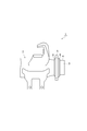
- a reduced diameter portion 4 having a reduced outer diameter is formed at the end 3 of the rear axle housing 2. That is, the end portion 3 of the rear axle housing 2 is formed in a cylindrical shape, and the reduced diameter portion 4 is formed by cutting the outer peripheral surface of the end portion 3 formed in the cylindrical shape.
- the outer diameter of the reduced diameter portion 4 is made slightly larger than the inner diameter of the brake flange 5 described later. Note that the end 3 can be cut by, for example, a general cutting machine.
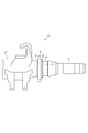
- a brake flange press-fitting process is then performed.
- the brake flange 5 is press-fitted into the outer peripheral surface of the reduced diameter portion 4.
- the brake flange 5 is a ring-shaped member for attaching a drum brake (not shown), and has a hole for attaching the drum brake along the circumferential direction.
- the press-fitting of the brake flange 5 into the reduced diameter portion 4 can be performed by, for example, a general press machine.
- the brake flange welding process is performed next. As shown in FIG. 3, in the brake flange welding process, the brake flange 5 is welded to the rear axle housing 2 (smaller diameter portion 4) on the entire circumference. The brake flange 5 is welded to the rear axle housing 2 both inside and outside the brake flange 5.
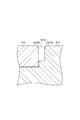
- a groove-shaped narrow groove 9 having a substantially U-shaped cross section in which the opposing surfaces are substantially parallel is formed at a location where the rear axle housing 2 and the brake flange 5 are joined. Keep it.
- the narrow groove 9 is defined by a brake flange facing surface 5a facing the rear axle housing 2 of the brake flange 5 and a rear axle housing facing surface 2a facing the brake flange 5 of the rear axle housing 2.
- the brake flange facing surface 5a and the rear axle housing facing surface 2a are substantially parallel to each other.
- the shape of the bottom surface of the narrow groove 9 is not particularly limited, and may be flat or curved.
- Cold tandem welding is a welding method using two wires, a leading welding wire and a trailing filler wire, in which a molten portion is formed in the groove by an arc generated by energizing the preceding welding wire. This is a welding method in which the subsequent filler wire is supplied to the molten portion without energization before the portion is cured.
- a welding device 11 that performs cold tandem welding includes an arc welding torch 12, a filler wire supply device 13, and a connecting member 14.
- the arc welding torch 12 performs arc welding.
- the arc welding torch 12 sends out a welding wire 16 as a consumable electrode sent out from the first wire sending device 15 toward the welding position of the base material. Further, the arc welding torch 12 energizes the welding wire 16 with the welding current supplied from the power supply device 17 to generate an arc between the welding wire 16 and the base material.
- the welding wire 16 for example, a solid wire conforming to JIS Z3312 YGW12 can be used.
- the filler wire supply device 13 sends the filler wire 19 delivered from the second wire delivery device 18 to a position close to the welding position of the base material without energization.
- the filler wire 19 for example, a solid wire conforming to JIS Z3312 YGW12 can be used.
- the connecting member 14 is used for arc welding while maintaining the distance between the arc welding torch 12 and the filler wire supply device 13 so that the welding position by the welding wire 16 and the position at which the filler wire 19 is sent out are at a predetermined distance.
- This is a device for connecting the torch 12 and the filler wire supply device 13.
- the connecting member 14 may detachably connect the arc welding torch 12 and the filler wire supply device 13, or may connect the arc welding torch 12 and the filler wire supply device 13 fixedly.
- the connection member 14 may fix the space
- the welding device 11 configured as described above is configured such that when the arc welding torch 12 and the filler wire supply device 13 connected to the connecting member 14 move relative to the base material, the filler wire A supply device 13 is disposed behind the arc welding torch 12. For this reason, the position where the filler wire 19 is sent out is behind the welding position by the welding wire 16 in the movement direction.
- the direction in which the arc welding torch 12 and the filler wire supply device 13 move relative to the base material is referred to as “traveling direction”.
- the arc welding torch 12 and the filler wire supply device 13 are moved relative to the rear axle housing 2 and the brake flange 5 as the base material along the narrow groove 9. Then, the arc welding torch 12 moves in advance of the filler wire supply device 13, and the filler wire supply device 13 moves behind the arc welding torch.
- the melting part 22 is composed of a molten pool.
- the melted portion 22 is dug down under the arc 21 by receiving pressure (arc force) from the arc 21, and the portion dug up most by the arc force becomes the bottom 22 a of the melted portion 22.
- the influence of the arc force is weakened and gradually rises and rises.
- the rising part 22b which the molten part 22 rose is formed in the advancing direction back of the bottom part 22a.
- the raised portion 22b is a portion made of molten metal before being hardened (solidified).
- the surging part 22b is cooled and hardened (solidified), and the surplus part 6 is formed in the junction location of the rear axle housing 2 and the brake flange 5.
- this surplus 6 is also called a bead.
- the filler wire 19 is supplied from the filler wire supply device 13 following the arc welding torch 12 to the rising portion 22b of the melting portion 22 without energization.
- the supply position of the filler wire 19 can be adjusted, for example, by adjusting the distance between the arc welding torch 12 and the filler wire supply device 13 by the connecting member 14 or adjusting the direction of the filler wire supply device 13.
- the filler wire 19 When the filler wire 19 is supplied to the rising part 22b of the melting part 22, the filler wire 19 is melted by the heat of the melting part 22, and the molten metal is replenished to the melting part 22. Thereby, the favorable surplus 6 is formed.
- the filler wire 19 that is not energized is not heated, when the filler wire 19 is supplied to the rising portion 22b of the melting portion 22, the heat of the melting portion 22 is taken away by the filler wire 19 and the melting portion 22 is cooled.
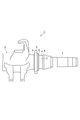
- the axle end press-fitting process is performed next.
- the axle end 7 is press-fitted into the inner peripheral surface of the end 3 of the rear axle housing 2.
- the axle end 7 is formed in a cylindrical shape, and its outer diameter is slightly larger than the inner diameter of the end 3 of the rear axle housing 2.
- the press-fit of the axle end 7 to the end portion 3 of the rear axle housing 2 can be performed by, for example, a general press machine.
- axle end welding process is performed next. As shown in FIG. 5, in the axle end welding process, the axle end 7 is welded to the rear axle housing 2 all around.
- a narrow groove 10 having a substantially U-shaped cross section in which the opposing surfaces are substantially parallel is formed at a position where the rear axle housing 2 and the axle end 7 are joined. deep.
- the narrow groove 10 is defined by a rear axle housing facing surface 2b facing the axle end 7 of the rear axle housing 2 and an axle end facing surface 7b facing the rear axle housing 2 of the axle end 7.
- the rear axle housing facing surface 2b and the axle end facing surface 7b are substantially parallel to each other.
- the rear axle housing 2 and the axle end 7 are arc-welded along the narrow groove 10 by cold tandem welding.
- Cold tandem welding is as described above. Thereby, between the rear axle housing 2 and the axle end 7, a surplus 8 is formed in which the melted portion 22 rises and is cooled and hardened (solidified).
- the rear axle 1 manufactured in this way has a reduced diameter portion 4 with a reduced outer diameter at the end 3 of the rear axle housing 2, and a brake flange on the outer peripheral surface of the reduced diameter portion 4. 5 is press-fitted, and the brake flange 5 is welded around the rear axle housing 2.
- an axle end 7 is press-fitted into the inner peripheral surface of the end 3 of the rear axle housing 2, and the axle end 7 is welded to the rear axle housing 2 on the entire circumference.
- the entire circumference welding of the brake flange 5 to the rear axle housing 2 is performed by cold tandem welding along the narrow groove 9, and the entire circumference welding of the axle end 7 to the rear axle housing 2 is performed by the narrow groove 10. It is done by cold tandem welding along.
- the brake flange 5 and the axle end 7 are press-fitted into the rear axle housing 2, and the brake flange 5 and the axle end 7 are welded to the rear axle housing 2 all around. Therefore, the rear axle 1 can be manufactured without going through the shrink fitting process. Thereby, since the manufacturing process can be simplified, it is possible to reduce the space and investment of the shrink fitting equipment, and to save resources and reduce exhaust CO 2 .
- the brake flange 5 can be easily press-fitted into the rear axle housing 2, and the rear axle housing 2 and the brake flange 5 can be Internal stress can be reduced.
- the molten portion 22 can be cooled by the cold filler wire 19. .
- the heat shrinkage range of the melting part 22 is narrowed, the heat shrinkage when the melting part 22 is cooled and hardened can be remarkably suppressed.
- the squareness of the brake flange 5 with respect to the rear axle housing 2 can be remarkably improved, and the swing of the axle end 7 with respect to the rear axle housing 2 can be remarkably suppressed.
- the amount of heat input to the rear axle housing 2, the brake flange 5, and the axle end 7 can be kept small.
- the molten metal is replenished to the melting part 22, so that a good surplus 6 and surplus 8 can be formed, resulting in poor welding such as humping. Can be suppressed. Further, since the residual stress can be remarkably reduced, a margin for reaching the yield point can be obtained, which can contribute to the improvement of the life compared to the conventional case.
- the groove width is narrower than the case where the groove is the Y groove by setting the groove to be the narrow groove 9 and the narrow groove 10, the thermal distortion of the extra bank 6 and the extra bank 8 (Heat shrinkage) can be reduced, and the amount of heat input to the rear axle housing 2, the brake flange 5, and the axle end 7 can be kept small.
- the perpendicularity of the brake flange 5 with respect to the rear axle housing 2 can be further improved, and the deflection of the axle end 7 with respect to the rear axle housing 2 can be improved.
- the narrow groove 9 and the narrow groove 10 are formed in a substantially U-shaped cross section in which the opposing surfaces are substantially parallel, fluctuations in the positional relationship between the members can be further suppressed.
- the filler wire 19 can be suppressed from being directly heated by the arc 21. For this reason, the cooling effect of the fusion
- the groove is described as a narrow groove, but a groove having another shape may be used.
- the brake flange 5 and the rear axle housing 2 are welded all around, and the axle end 7 and the rear axle housing 2 are welded all around. There is no need.
- the brake flange press-fitting process, the brake flange welding process, the axle end press-fitting process, and the axle end welding process are performed in this order, but the order of these processes can be changed as appropriate.
- the brake flange press-fitting process, the axle end press-fitting process, the brake flange welding process, and the axle end welding process may be performed in this order.
Landscapes
- Engineering & Computer Science (AREA)
- Mechanical Engineering (AREA)
- Physics & Mathematics (AREA)
- Plasma & Fusion (AREA)
- Butt Welding And Welding Of Specific Article (AREA)
- Arc Welding In General (AREA)
Abstract
La présente invention concerne un procédé de fabrication d'un essieu arrière comprenant les étapes suivantes : une étape d'emmanchement à la presse de flasque de frein, destinée à emmancher à la presse une flasque de frein à la surface périphérique externe d'un carter d'essieu arrière ; une étape de soudage de flasque de frein, destinée à souder l'un à l'autre le carter d'essieu arrière et la flasque de frein ; une étape d'emmanchement à la presse d'extrémité d'essieu, destinée à emmancher à la presse une extrémité d'essieu à la surface périphérique interne d'une extrémité du carter d'essieu arrière ; et une étape de soudage d'extrémité d'essieu, destinée à souder l'un à l'autre le carter d'essieu arrière et l'extrémité d'essieu.
Priority Applications (3)
| Application Number | Priority Date | Filing Date | Title |
|---|---|---|---|
| CN201380039368.2A CN104507704B (zh) | 2012-07-26 | 2013-05-24 | 后轴的制造方法及后轴 |
| US14/407,147 US10118442B2 (en) | 2012-07-26 | 2013-05-24 | Method for manufacturing rear axle, and rear axle |
| EP13822967.9A EP2878456B1 (fr) | 2012-07-26 | 2013-05-24 | Procédé de fabrication d'essieu arrière, et essieu arrière |
Applications Claiming Priority (2)
| Application Number | Priority Date | Filing Date | Title |
|---|---|---|---|
| JP2012-165856 | 2012-07-26 | ||
| JP2012165856A JP6430094B2 (ja) | 2012-07-26 | 2012-07-26 | リアアクスルの製造方法 |
Publications (1)
| Publication Number | Publication Date |
|---|---|
| WO2014017158A1 true WO2014017158A1 (fr) | 2014-01-30 |
Family
ID=49996976
Family Applications (1)
| Application Number | Title | Priority Date | Filing Date |
|---|---|---|---|
| PCT/JP2013/064478 Ceased WO2014017158A1 (fr) | 2012-07-26 | 2013-05-24 | Procédé de fabrication d'essieu arrière, et essieu arrière |
Country Status (5)
| Country | Link |
|---|---|
| US (1) | US10118442B2 (fr) |
| EP (1) | EP2878456B1 (fr) |
| JP (1) | JP6430094B2 (fr) |
| CN (1) | CN104507704B (fr) |
| WO (1) | WO2014017158A1 (fr) |
Families Citing this family (3)
| Publication number | Priority date | Publication date | Assignee | Title |
|---|---|---|---|---|
| AU2017278058B2 (en) | 2016-06-09 | 2022-07-07 | Gagnon Family Trust | Wheel end assembly and spindle configured therefor |
| JP6748017B2 (ja) * | 2017-04-06 | 2020-08-26 | 日野自動車株式会社 | アクスルの製造方法 |
| CN110524131B8 (zh) * | 2019-07-25 | 2024-04-23 | 宿州德润机械有限公司 | 一种焊接梁总成工艺 |
Citations (8)
| Publication number | Priority date | Publication date | Assignee | Title |
|---|---|---|---|---|
| US2480833A (en) * | 1944-09-02 | 1949-09-06 | Timken Axle Co Detroit | Axle housing |
| JPS49130850A (fr) * | 1973-04-23 | 1974-12-14 | ||
| JPS5999804U (ja) * | 1982-12-24 | 1984-07-05 | 日野自動車株式会社 | アクスルハウジング |
| JPH0216294U (fr) * | 1988-07-11 | 1990-02-01 | ||
| JPH02286992A (ja) * | 1989-04-28 | 1990-11-27 | Kurimoto Ltd | 金属管へのフランジ取付方法 |
| JPH0491501U (fr) * | 1990-12-27 | 1992-08-10 | ||
| JPH05330355A (ja) | 1992-06-01 | 1993-12-14 | Toyota Autom Loom Works Ltd | アクスルハウジングにおけるデフハウジング |
| JP2008055506A (ja) * | 2006-07-31 | 2008-03-13 | Daihen Corp | 2溶接ワイヤ送給アーク溶接方法及び多層盛り溶接方法及び狭開先溶接方法 |
Family Cites Families (17)
| Publication number | Priority date | Publication date | Assignee | Title |
|---|---|---|---|---|
| US1955824A (en) | 1930-06-16 | 1934-04-24 | Clark Equipment Co | Rear axle housing |
| JPS51116135A (en) | 1975-04-05 | 1976-10-13 | Kobe Steel Ltd | Method of welding aluminum and its alloy |
| JPS586602A (ja) | 1981-07-03 | 1983-01-14 | Sumitomo Electric Ind Ltd | アクテイブアンテナ |
| JPS5876403A (ja) | 1981-11-02 | 1983-05-09 | Kuraray Co Ltd | 架橋性基を有する変性ポリビニルアルコ−ル |
| JPS5999804A (ja) | 1982-11-29 | 1984-06-08 | Toshiba Corp | モノパルスホ−ンアンテナ装置 |
| JPH0696950B2 (ja) | 1988-07-01 | 1994-11-30 | 佐藤工業株式会社 | シールド掘削機 |
| JPH0491501A (ja) | 1990-08-07 | 1992-03-25 | Matsushita Electric Ind Co Ltd | 誘電体フィルタ |
| JPH0663754A (ja) * | 1992-08-20 | 1994-03-08 | Hitachi Zosen Corp | ガスシールドアーク溶接法 |
| US5724657A (en) * | 1995-09-29 | 1998-03-03 | Rockwell International Corporation | Adaptive frequency correction burst detector for GSM handset system |
| JP2001050413A (ja) | 1999-08-05 | 2001-02-23 | Kubota Corp | バルブ |
| JP2001277812A (ja) * | 2000-03-31 | 2001-10-10 | Nissan Diesel Motor Co Ltd | アクスルハウジング |
| EP1350975A3 (fr) * | 2002-04-04 | 2004-06-30 | Dana Corporation | Ensemble d'arbre d'entraínement véhiculaire avec forchette pour joint universel |
| CN2717733Y (zh) | 2004-07-27 | 2005-08-17 | 杨东洲 | 汽车整体式驱动桥壳 |
| KR100831643B1 (ko) * | 2007-04-10 | 2008-05-22 | 류충오 | 연결 조인트 및 이를 구비한 복합재료 드라이브 샤프트어셈블리 |
| CN201520164U (zh) | 2009-10-20 | 2010-07-07 | 中国三江航天工业集团公司特种车辆技术中心 | 一种整体式桥壳总成 |
| JP5260469B2 (ja) | 2009-10-26 | 2013-08-14 | 株式会社神戸製鋼所 | ガスシールドアーク溶接方法 |
| US20110101771A1 (en) * | 2009-11-04 | 2011-05-05 | Oswaldo De Freitas Junior | Steering axle |
-
2012
- 2012-07-26 JP JP2012165856A patent/JP6430094B2/ja active Active
-
2013
- 2013-05-24 WO PCT/JP2013/064478 patent/WO2014017158A1/fr not_active Ceased
- 2013-05-24 CN CN201380039368.2A patent/CN104507704B/zh not_active Expired - Fee Related
- 2013-05-24 US US14/407,147 patent/US10118442B2/en not_active Expired - Fee Related
- 2013-05-24 EP EP13822967.9A patent/EP2878456B1/fr not_active Not-in-force
Patent Citations (8)
| Publication number | Priority date | Publication date | Assignee | Title |
|---|---|---|---|---|
| US2480833A (en) * | 1944-09-02 | 1949-09-06 | Timken Axle Co Detroit | Axle housing |
| JPS49130850A (fr) * | 1973-04-23 | 1974-12-14 | ||
| JPS5999804U (ja) * | 1982-12-24 | 1984-07-05 | 日野自動車株式会社 | アクスルハウジング |
| JPH0216294U (fr) * | 1988-07-11 | 1990-02-01 | ||
| JPH02286992A (ja) * | 1989-04-28 | 1990-11-27 | Kurimoto Ltd | 金属管へのフランジ取付方法 |
| JPH0491501U (fr) * | 1990-12-27 | 1992-08-10 | ||
| JPH05330355A (ja) | 1992-06-01 | 1993-12-14 | Toyota Autom Loom Works Ltd | アクスルハウジングにおけるデフハウジング |
| JP2008055506A (ja) * | 2006-07-31 | 2008-03-13 | Daihen Corp | 2溶接ワイヤ送給アーク溶接方法及び多層盛り溶接方法及び狭開先溶接方法 |
Non-Patent Citations (1)
| Title |
|---|
| See also references of EP2878456A4 |
Also Published As
| Publication number | Publication date |
|---|---|
| CN104507704A (zh) | 2015-04-08 |
| EP2878456A4 (fr) | 2017-03-08 |
| CN104507704B (zh) | 2018-01-02 |
| US10118442B2 (en) | 2018-11-06 |
| JP2014024443A (ja) | 2014-02-06 |
| JP6430094B2 (ja) | 2018-11-28 |
| EP2878456B1 (fr) | 2018-03-28 |
| US20150158335A1 (en) | 2015-06-11 |
| EP2878456A1 (fr) | 2015-06-03 |
Similar Documents
| Publication | Publication Date | Title |
|---|---|---|
| US10873239B2 (en) | Electric machine cooling features | |
| US11296583B2 (en) | Core manufacturing method and core | |
| US10603740B2 (en) | Method of joining by electron beam or laser welding a turbocharger turbine wheel to a shaft; corresponding turbocharger turbine wheel | |
| JP2013018035A (ja) | 溶接構造、及び溶接方法 | |
| JP6430094B2 (ja) | リアアクスルの製造方法 | |
| JP6328367B2 (ja) | プロペラシャフトの製造方法及びプロペラシャフト | |
| JP6446502B2 (ja) | リアアクスルの製造方法 | |
| JP5220449B2 (ja) | 金属部材の接合方法及びその装置 | |
| US11161196B2 (en) | Metallic member bonding device for pressing rod-shaped or cylindrical first metallic member into hole portion of annular second metallic member to bond the same and bonding method therefor | |
| JP2012223799A (ja) | 溶接継手の製造方法 | |
| JP6748017B2 (ja) | アクスルの製造方法 | |
| JP6098150B2 (ja) | アクスルハウジングの製造方法 | |
| US9825432B2 (en) | Spark plug for internal combustion engine and production method thereof | |
| JP2010069520A (ja) | 金属部材の接合方法及びその接合装置 | |
| JP2014014823A (ja) | 溶接方法 | |
| JP6882581B1 (ja) | 接合物品の製造方法及び製造装置 | |
| JP6644404B2 (ja) | 溶接構造および溶接方法 | |
| JP2017132467A (ja) | プロペラシャフトの製造方法 | |
| JP2019048334A (ja) | 溶接部形成構造及び金属部材の接合方法 | |
| JP2015217396A (ja) | 金属中空部材の摩擦圧接方法および発電設備用部材 | |
| JPS63134874A (ja) | 全密閉形圧縮機 | |
| JP2014083549A (ja) | 摩擦圧接装置 |
Legal Events
| Date | Code | Title | Description |
|---|---|---|---|
| 121 | Ep: the epo has been informed by wipo that ep was designated in this application |
Ref document number: 13822967 Country of ref document: EP Kind code of ref document: A1 |
|
| WWE | Wipo information: entry into national phase |
Ref document number: 14407147 Country of ref document: US |
|
| NENP | Non-entry into the national phase |
Ref country code: DE |
|
| WWE | Wipo information: entry into national phase |
Ref document number: 2013822967 Country of ref document: EP |