WO2014017208A1 - Dispositif de transport de fluide et procédé de transport de fluide - Google Patents
Dispositif de transport de fluide et procédé de transport de fluide Download PDFInfo
- Publication number
- WO2014017208A1 WO2014017208A1 PCT/JP2013/066321 JP2013066321W WO2014017208A1 WO 2014017208 A1 WO2014017208 A1 WO 2014017208A1 JP 2013066321 W JP2013066321 W JP 2013066321W WO 2014017208 A1 WO2014017208 A1 WO 2014017208A1
- Authority
- WO
- WIPO (PCT)
- Prior art keywords
- fluid
- jet
- transported
- vortex ring
- nozzle
- Prior art date
- Legal status (The legal status is an assumption and is not a legal conclusion. Google has not performed a legal analysis and makes no representation as to the accuracy of the status listed.)
- Ceased
Links
Images



















Classifications
-
- F—MECHANICAL ENGINEERING; LIGHTING; HEATING; WEAPONS; BLASTING
- F15—FLUID-PRESSURE ACTUATORS; HYDRAULICS OR PNEUMATICS IN GENERAL
- F15D—FLUID DYNAMICS, i.e. METHODS OR MEANS FOR INFLUENCING THE FLOW OF GASES OR LIQUIDS
- F15D1/00—Influencing flow of fluids
- F15D1/009—Influencing flow of fluids by means of vortex rings
-
- F—MECHANICAL ENGINEERING; LIGHTING; HEATING; WEAPONS; BLASTING
- F24—HEATING; RANGES; VENTILATING
- F24F—AIR-CONDITIONING; AIR-HUMIDIFICATION; VENTILATION; USE OF AIR CURRENTS FOR SCREENING
- F24F13/00—Details common to, or for air-conditioning, air-humidification, ventilation or use of air currents for screening
- F24F13/02—Ducting arrangements
- F24F13/06—Outlets for directing or distributing air into rooms or spaces, e.g. ceiling air diffuser
-
- F—MECHANICAL ENGINEERING; LIGHTING; HEATING; WEAPONS; BLASTING
- F24—HEATING; RANGES; VENTILATING
- F24F—AIR-CONDITIONING; AIR-HUMIDIFICATION; VENTILATION; USE OF AIR CURRENTS FOR SCREENING
- F24F13/00—Details common to, or for air-conditioning, air-humidification, ventilation or use of air currents for screening
- F24F13/02—Ducting arrangements
- F24F13/06—Outlets for directing or distributing air into rooms or spaces, e.g. ceiling air diffuser
- F24F2013/0612—Induction nozzles without swirl means
Definitions
- the present invention relates to a fluid transport apparatus and a fluid transport method for ejecting a fluid to be transported such as a gas or a liquid from a jet part into a space and locally transporting the target fluid away from the jet part while suppressing diffusion.
- Patent Document 1 discloses a gas to be transported blown from a blower outlet as a gas transport method for blowing the gas to be transported from a blower outlet toward a target location into the space to reach the target gas to the target location.
- the annular forming gas rotates in a vortex around the center of the cross section, and advances in space toward the target location.
- the gas to be transported is blown out from the outlet by a pulse-like flow rate variation, so that the vortex ring is formed and the gas to be transported is stored in the vortex ring at the same time.
- the transported gas cannot be stored continuously in the vortex ring. That is, in the conventional method, it is difficult to continuously transport the gas to be transported to a target point away from the target gas while suppressing diffusion.
- a fluid transport apparatus and a fluid capable of locally transporting a transported fluid such as a gas or a liquid from the ejection portion into the space and suppressing diffusion to a target location away from the ejection portion.
- the fluid transfer device supplies a to-be-transferred fluid to the outside of the transfer fluid at a lower speed than the center speed of the transfer fluid by ejecting the transfer fluid from the outlet into the space and forming a vortex ring. And a transported fluid supply means.
- the fluid transfer method of the present invention forms a vortex ring by ejecting the transfer fluid from the outlet into the space, and supplies the transfer target fluid to the outside of the transfer fluid at a lower speed than the center speed of the transfer fluid. It is characterized by that.
- the transported fluid supplied to the outside of the transport fluid at a speed lower than the center speed of the transport fluid is directly into the vortex ring formed by the transport fluid being rolled up at the ejection port. Stored and transported with vortex ring.
- the transported fluid supply means is a flow path for discharging the transported fluid along the wall surface of the ejection portion.
- a vortex ring is formed when the carrier fluid rolls up at the jet outlet around the fluid to be transported discharged along the wall surface of the ejection portion, so that the fluid to be transported is stored in the center of the vortex ring.
- the transported fluid supply means when the heated fluid or the cooled fluid is transported to the target location, the transported fluid supply means generates the transported fluid by a heating source or a cooling source provided on the wall surface of the ejection portion. It can be.
- the carrier fluid forming the vortex ring is heated or cooled by the heating source or the cooling source provided on the wall surface of the ejection part, and the vortex ring is formed around the heated or cooled portion of the carrier fluid. be able to.
- another fluid transfer device of the present invention includes a first jet port that jets a transported fluid under a condition of a laminar flow jet, and a first jet port that surrounds the outer periphery of the first jet port. It has an annular shape with a width of 1 ⁇ 2 or less of the diameter of the inscribed circle, and has a second ejection port that ejects the second fluid as an annular jet.
- Another fluid transfer method is such that the transfer target fluid is jetted from the first jet outlet under the condition of a laminar jet, and the first jet outlet is surrounded by the outer periphery of the first jet outlet.
- the second fluid is ejected as an annular jet from a second ejection port formed in an annular shape with a width of 1 ⁇ 2 or less of the diameter of the inscribed circle.
- the to-be-conveyed fluid (henceforth, the cyclic
- the speed of the transported fluid (main jet) ejected from the first ejection port (the volume flow rate of the transported fluid ejected from the first ejection port divided by the cross-sectional area of the first ejection port) U m
- the speed of the second fluid (annular jet) ejected from the second ejection port (the volume flow rate of the second fluid ejected from the second ejection port divided by the cross-sectional area of the second ejection port)
- the vortex ring is formed by ejecting the conveyance fluid from the ejection port into the space, and the fluid to be conveyed is lower than the center velocity of the conveyance fluid outside the conveyance fluid.
- the transported fluid supplied to the outside of the transport fluid at a speed lower than the center speed of the transport fluid directly enters the vortex ring formed by the transport fluid rolling up at the jet outlet.
- the stored fluid can be locally transported together with the vortex ring while suppressing diffusion to a target location away from the jet outlet.
- the fluid to be conveyed is ejected from the first ejection port under the condition of a laminar flow jet, and the first fluid ejection device surrounds the outer periphery of the first ejection port.
- the annular jet functions as an air curtain by ejecting the second fluid as an annular jet from a second jet formed in an annular shape with a width of 1 ⁇ 2 or less of the diameter of the inscribed circle of one jet. It is possible to suppress the diffusion of the transported fluid and to transport the transported fluid locally while maintaining the transported fluid in the annular jet.
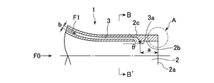
- FIG. 2 is a cross-sectional view taken along the line B-B ′ of the nozzle of FIG. 1. It is the A section enlarged view which shows the modification of the front-end
- FIG. 3 is a schematic diagram illustrating a method for storing thermal fluid in a vortex ring.
- FIG. 3 is a schematic diagram illustrating a method for storing thermal fluid in a vortex ring.
- FIG. 3 is a schematic diagram illustrating a method for storing thermal fluid in a vortex ring.
- FIG. 3 is a schematic diagram illustrating a method for storing thermal fluid in a vortex ring.
- FIG. 3 is a schematic diagram illustrating a method for storing thermal fluid in a vortex ring.
- FIG. 1 is an enlarged cross-sectional view of the vicinity of a nozzle outlet constituting the fluid conveyance device according to the first embodiment of the present invention
- FIG. 2 is a cross-sectional view of the nozzle of FIG.
- the fluid conveyance device 1 according to the first embodiment of the present invention is a cylindrical nozzle as an ejection portion that forms a vortex ring by ejecting the conveyance fluid F0 from the ejection port 2a into the space. 2 is provided.
- the fluid transport device 1 discharges the transported fluid F1 along the inner wall surface 2b of the nozzle 2 as transported fluid supply means for supplying the transported fluid F1 to the outside of the transport fluid F0 in the vicinity of the jet nozzle 2a.
- a flow path 3 is provided.
- the flow path 3 is an annular small flow path formed in the wall of the cylindrical nozzle 2 as shown in FIG.
- the to-be-conveyed fluid F1 is sent out from the jet outlet 3a of the flow path 3 toward the flow field of the carrier fluid F0 inside the nozzle 2.
- the distance a of the nozzle 3 of the flow channel 3 from the nozzle 2 to the nozzle 2a, the merge angle ⁇ of the flow channel 3 to the nozzle 2 and the width b of the flow channel 3 can be arbitrarily set. It is desirable to set so that the transport fluid F1 is transported along the inner wall surface 2b of the nozzle 2 to the jet outlet 2a.
- the flow path 3 may be formed partially or at a predetermined interval without being formed in a ring shape over the entire circumference.
- the continuous formation of the vortex ring by the carrier fluid F0 is performed by varying the ejection flow rate of the carrier fluid F0 ejected from the ejection port 2a over time.
- the waveform of the flow rate variation for example, the following periodic, intermittent or arbitrarily varying waveform can be used.
- the travel speed, strength (difficult to attenuate) and reachable distance can be adjusted by changing the waveform amplitude, period, intermittent period length and waveform combination order shown above. is there.
- the transported fluid F1 is pressurized by applying an arbitrary pressure to the upstream side of the flow path 3 or by increasing the pressure on the upstream side of the flow path 3 in accordance with the flow rate fluctuation of the flow. Then, the air is sent out from the jet outlet 3a to the outside of the carrier fluid F0 at a speed lower than the center speed of the carrier fluid F0. Or it is also possible to send out without pressurizing using the pressure difference which arises by the fluctuation
- the ejection flow rate of the transported fluid F1 ejected from the flow path 3 is made constant while the ejection flow rate of the transported fluid F0 ejected from the ejection port 2a is constant. It is also possible to change the time under conditions where the speed is lower than that.
- the waveforms of (1) to (7) can be used.
- the tip of the nozzle 2 is perpendicular to the central axis of the nozzle 2 as shown in part A of FIG. 1, and the outer wall surface 2c side is tapered as shown in FIG. 3A. As shown, the inner wall surface 2b side may be tapered.
- the one shown in FIG. 3A is most desirable, and the next desirable one is that shown in part A of FIG.
- an ejection portion such as an orifice.
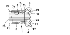
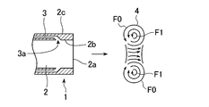
- FIG. 4A to 4C are explanatory views showing the state of fluid conveyance by the fluid conveyance device 1 of FIG. While supplying the transported fluid F1 from the flow path 3 to the outside of the transport fluid F0 at a lower speed than the center speed of the transport fluid F0, for example, the transport fluid F0 is intermittently introduced into the space from the jet outlet 3a as described above.
- the transported fluid F1 is directly stored in the vortex ring 4 formed by the transport fluid F0 being rolled up at the ejection port 3a as shown in FIG. 4A, and transported together with the vortex ring 4 as shown in FIG. 4B. Is done.
- FIG. 4C By performing this intermittently, as shown in FIG. 4C, it is possible to transport the transported fluid F1 locally while suppressing diffusion of the transported fluid F1 to a target location that is continuously away from the ejection port 3a at predetermined time intervals. It becomes possible.
- the jet outlet 3a of the flow path 3 for discharging the transported fluid F1 is provided on the inner wall surface 2b of the nozzle 2, but the jet outlet 3a is provided on the outer wall face 2c side of the nozzle 2. Or provided on both the inner wall surface 2b and the outer wall surface 2c.
- the transported fluid F1 is supplied to the outside of the transport fluid F0 at a lower speed than the center speed of the transport fluid F0, and directly into the vortex ring 4 formed by the transport fluid F0 rolling up at the jet outlet 3a. It may be configured to be stored in.
- FIG. 5 is an enlarged cross-sectional view of the vicinity of the nozzle outlet constituting the fluid conveyance device in the second embodiment of the present invention.
- the fluid conveyance device 5 according to the second embodiment of the present invention further includes a cylindrical nozzle 7 inside the cylindrical nozzle 6.
- the carrier fluid F0 is supplied by the inner nozzle 7, and is intermittently ejected into the space from the ejection port 6a of the nozzle 6.
- the transported fluid F1 is supplied to the outside of the transport fluid F0 from the annular flow path 8 formed between the nozzle 6 and the nozzle 7 at a lower speed than the center speed of the transport fluid F0.
- the carrier fluid F0 is supplied from the nozzle 7 with a constant ejection flow rate, and is ejected from the ejection port 6a of the nozzle 6 into the space at a constant flow rate.
- the transported fluid F1 is intermittently supplied from the annular flow path 8 to the outside of the transport fluid F0 under a condition that the speed is lower than the center speed of the transport fluid F0.
- the distance (distance from the spout 7a of the nozzle 7 to the spout 6a) a from the spout 8a of the flow path 8 to the spout 6a of the nozzle 6 and the width b of the flow path 8 should be set arbitrarily.
- the method for sending out the transported fluid F1 from the flow path 8 is the same as in the first embodiment.
- the shapes of the tip portions of the nozzles 6 and 7 are the same as in the first embodiment.
- the fluid to be transported F1 is supplied from the flow path 8 to the outside of the transport fluid F0 at a lower speed than the center speed of the transport fluid F0, and is intermittently transported from the jet nozzle 6a into the space.
- the to-be-conveyed fluid F1 is directly stored in the vortex ring formed by the conveyance fluid F0 rolling up at the jet nozzle 6a, and is conveyed together with the vortex ring.
- the ejection flow rate of the transported fluid F1 supplied from the flow path 8 is set while the ejection flow rate of the transport fluid F0 supplied from the nozzle 7 is constant and the ejection flow rate is ejected from the ejection port 6a of the nozzle 6 into the space.
- the carrier fluid F0 is also rolled up and a vortex ring is formed by intermittently supplying the carrier fluid F0 outside the carrier fluid F0 at a speed lower than the center speed of the carrier fluid F0. Direct storage in the vortex ring is possible.
- the jet nozzle 7a of the nozzle 7 which supplies the conveyance fluid F0 is arrange
- the jet nozzle 7a of the nozzle 7 is the jet of nozzle 6. It is also possible to adopt a configuration in which the jet outlet 7a of the nozzle 7 and the jet outlet 6a of the nozzle 6 are arranged on the same plane.
- the transported fluid F1 is supplied from the annular flow path 8 formed between the nozzle 6 and the nozzle 7 to the outside of the transport fluid F0 at a lower speed than the center speed of the transport fluid F0.
- the transported fluid F1 is directly stored in the vortex ring formed by the transport fluid F0 ejected into the space from the ejection port 7a of the nozzle 7 and transported together with the vortex ring.
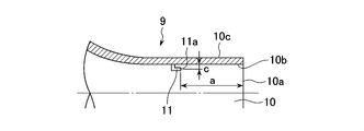
- FIG. 6 is an enlarged cross-sectional view of the vicinity of the nozzle outlet constituting the fluid conveyance device in the third embodiment of the present invention.
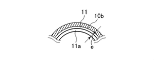
- the fluid conveyance device 9 in the third embodiment of the present invention supplies the fluid F ⁇ b> 1 to be conveyed onto the inner wall surface 10 b of the cylindrical nozzle 10 that intermittently ejects the conveyance fluid F ⁇ b> 0 into the space.
- the nozzle 11 which comprises the flow path to perform is provided.
- the nozzle 11 has a configuration in which one or a plurality of circular tube-shaped jet nozzles 11a are arranged on the inner wall surface 10b at predetermined intervals, or along the inner wall surface 10b as shown in FIG. 7B. It is possible to adopt a configuration in which an annular jet 11a is arranged.
- the carrier fluid F0 is ejected from the nozzle 10 into the space at a constant flow rate.
- the transported fluid F1 is intermittently supplied from the ejection port 11a of the nozzle 11 to the outside of the transport fluid F0 under a condition that the speed is lower than the center speed of the transport fluid F0.
- the distance a from the nozzle 11a to the nozzle 10a, the height c from the inner wall 10b of the nozzle 10 to the center of the nozzle 11a, and the inner diameter of the annular outlet 11a. ⁇ d and the width e of the ring-shaped ejection port 11 can be arbitrarily set, but the transported fluid F1 ejected from the ejection port 11a of the nozzle 11 is ejected along the inner wall surface 10b of the nozzle 10. It is desirable to set so as to be carried to the outlet 10a. Further, the method for sending out the transported fluid F1 from the nozzle 11 is the same as in the first embodiment. Further, the shape of the tip of the nozzle 10 is the same as in the first embodiment.
- the fluid to be transported F1 is supplied from the outlet 11a of the nozzle 11 to the outside of the carrier fluid F0 at a lower speed than the center speed of the carrier fluid F0, and intermittently from the outlet 10a to the space.
- the transported fluid F1 is directly stored in the vortex ring formed by the transport fluid F0 being rolled up at the ejection port 10a, and is transported together with the vortex ring.
- the transported fluid F1 is intermittently supplied from the jet port 11a of the nozzle 11 to the outside of the transport fluid F0 at a lower speed than the center speed of the transport fluid F0, and the transport fluid is transferred from the jet port 10a into the space.
- the transported fluid F1 is directly stored in the vortex ring formed by the transport fluid F0 being rolled up at the ejection port 10a, and is transported together with the vortex ring.
- the nozzle 11 that discharges the transported fluid F1 is provided on the inner wall surface 10b of the nozzle 10, but the nozzle 11 is provided on the outer wall surface 10c side of the nozzle 10, or the inner wall surface 10b and It is also possible to provide both on the outer wall surface 10c.
- the transported fluid F1 is supplied to the outside of the transport fluid F0 at a lower speed than the center speed of the transport fluid F0, and directly into the vortex ring formed by the transport fluid F0 rolling up at the jet outlet 10a. What is necessary is just to comprise so that it may be stored.
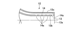
- FIG. 8 is an enlarged cross-sectional view of the vicinity of the nozzle outlet constituting the fluid conveyance device in the fourth embodiment of the present invention.
- the fluid conveyance device 12 according to the fourth embodiment of the present invention supplies a fluid F1 to be conveyed into the wall surface of a cylindrical nozzle 13 that intermittently ejects the conveyance fluid F0 into the space.
- the small space 14 which comprises is provided.
- the inner wall surface 13b of the nozzle 13 is provided with an opening 14a such as a hole or a slit for supplying the transported fluid F1 from the small space 14 to the outside of the transport fluid F0.
- the carrier fluid F0 is ejected from the nozzle 13 into the space at a constant flow rate.
- the transported fluid F1 is intermittently supplied from the opening 14a provided in the small space 14 to the outside of the transport fluid F0 under a condition that the speed is lower than the center speed of the transport fluid F0.
- the size and volume of the small space 14, the size of the opening 14a, the installation position, the installation interval, and the number of the small space 14 can be arbitrarily set, but the transported fluid F1 ejected from the opening 14a is the nozzle 13 It is desirable to set so that it may be conveyed to the jet nozzle 13a along the inner wall surface 13b. Further, the delivery method of the transported fluid F1 is the same as in the first embodiment. Further, the shape of the tip of the nozzle 13 is the same as that in the first embodiment.
- the fluid to be transported F1 is supplied from the opening 14a of the small space 14 to the outside of the transport fluid F0 at a lower speed than the center speed of the transport fluid F0, and the space from the jet outlet 13a is intermittently supplied.
- the transported fluid F1 is directly stored in the vortex ring formed by the transport fluid F0 being rolled up at the ejection port 13a, and is transported together with the vortex ring.
- the fluid to be transported F1 is intermittently supplied from the opening 14a of the small space 14 to the outside of the transport fluid F0 at a speed lower than the center speed of the transport fluid F0, and then into the space from the jet outlet 13a.
- the transported fluid F1 is directly stored in the vortex ring formed by the transport fluid F0 being rolled up at the ejection port 13a, and is transported together with the vortex ring.
- the opening 14a for ejecting the transported fluid F1 from the small space 14 is provided on the inner wall surface 13b of the nozzle 13, but it is provided on the outer wall surface 13c side of the nozzle 13 or the inner wall surface. It is also possible to provide both on 13b and the outer wall surface 13c.
- the transported fluid F1 is supplied to the outside of the transport fluid F0 at a speed lower than the center speed of the transport fluid F0, and directly into the vortex ring formed by the transport fluid F0 rolling up at the jet outlet 13a. What is necessary is just to comprise so that it may be stored.
- FIG. 9 is an enlarged cross-sectional view of the vicinity of the nozzle outlet constituting the fluid conveyance device in the fifth embodiment of the present invention.
- the fluid conveyance device 15 according to the fifth embodiment of the present invention supplies a fluid F1 to be conveyed into the wall surface of a cylindrical nozzle 16 that intermittently ejects the conveyance fluid F0 into the space.
- the small space 17 which comprises is provided.
- Inner wall surface 16b of the nozzle 16 Is provided with an opening 17a for supplying the transported fluid F1 from the small space 17 to the outside of the transport fluid F0.
- the opening 17a is provided with a filter material 18 made of a porous material, a fiber material, a permeable membrane, or the like.
- the dimensions and volume of the small space 17, the dimensions of the opening 17a and the filter material 18, the installation position, the installation interval and the number can be arbitrarily set, but the opening 17a through the filter material 18 can be set. It is desirable to set so that the fluid to be transported F1 to be ejected is conveyed along the inner wall surface 16b of the nozzle 16 to the ejection port 16a. Further, the delivery method of the transported fluid F1 is the same as in the first embodiment. Further, the shape of the tip of the nozzle 16 is the same as that of the first embodiment.
- the transported fluid F1 is intermittently supplied from the opening 17a of the small space 17 to the outside of the transport fluid F0 through the filter member 18 at a speed lower than the center speed of the transport fluid F0.
- the transported fluid F1 is directly stored in the vortex ring formed by the transport fluid F0 rolling up at the jet outlet 16a, and is transported together with the vortex ring. .
- intermittently performing this it is possible to transport the transported fluid F1 locally while suppressing diffusion of the transported fluid F1 to a target location that is continuously away from the ejection port 16a at predetermined time intervals.
- the opening 17a for ejecting the transported fluid F1 from the small space 17 and the filter material 18 are provided on the inner wall surface 16b of the nozzle 16, but are provided on the outer wall surface 16c side of the nozzle 16. Or provided on both the inner wall surface 16b and the outer wall surface 16c.
- the transported fluid F1 is supplied to the outside of the transport fluid F0 at a lower speed than the center speed of the transport fluid F0, and directly into the vortex ring formed by the transport fluid F0 rolling up at the jet port 16a. What is necessary is just to comprise so that it may be stored.
- FIG. 10 is an enlarged cross-sectional view of the vicinity of the nozzle outlet constituting the fluid conveyance device in the sixth embodiment of the present invention.
- the fluid conveyance device 19 in the sixth embodiment of the present invention conveys a heated fluid to a target location, and as shown in FIG. 10, a cylindrical nozzle that intermittently ejects the conveyance fluid F0 into the space.
- the heating source 21 is provided on the inner wall surface 20b and the outer wall surface 20c.
- region which provides the heat source 21, an installation position, and an installation area can be set arbitrarily.
- the shape of the tip of the nozzle 20 is the same as in the first embodiment.
- the heating source 21 is provided on both the inner peripheral surface 20b and the outer peripheral surface 20c of the nozzle 20, but a configuration provided on only one of them may be employed.
- the carrier fluid F1 heated outside the carrier fluid F0 is generated and supplied at a lower speed than the center speed of the carrier fluid F0, and the carrier fluid F0 is rolled up at the jet outlet 20a. What is necessary is just to comprise so that it may store directly in a vortex ring.
- FIG. 21 is an enlarged cross-sectional view of the vicinity of a jet nozzle of a double nozzle constituting a fluid conveyance device in a seventh embodiment of the present invention.
- the fluid transfer device according to the seventh embodiment of the present invention includes a first jet port 31 and an annular second jet formed so as to surround the outer periphery of the first jet port 31.
- a double nozzle 30 comprising an outlet 32 is provided.
- the first jet port 31 is cylindrical
- the second jet port 32 is coaxial with the first jet port 31 and has a central axis that is 1 in diameter of the first jet port 31. It is an annular shape formed with a width of / 2 or less.
- a to-be-conveyed fluid is jetted on the conditions used as a laminar flow jet.
- a second fluid different from the transported fluid ejected from the first ejection port 31 is ejected from the second ejection port 32 as an annular jet.
- the second fluid can be the same fluid as the transported fluid.
- the velocity of the second fluid to be ejected from the second ejecting port 32 has a U a
- speed U m of the carrier fluid The ratio U a / U m of the velocity U a of the second fluid is 0.25 ⁇ U a / U m ⁇ 2 To be.
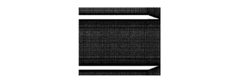
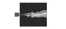
- FIG. 22 shows a visualization photograph of the fluid ejected from the tip of the double nozzle 30 of FIG.
- the annular jet ejected from the second ejection port 32 functions as an air curtain and ejects from the first ejection port 31 under the condition of forming a laminar flow jet. Since the diffusion of the transported fluid to be transported is suppressed, it is possible to transport the transported fluid locally while maintaining the transported fluid in the annular jet.
- the position of the first jet port 31 and the position of the second jet port 32 are preferably the same as shown in FIG. If it is within the range, even if a difference occurs between the positions of the two jet nozzles, the annular jet jetted from the second jet nozzle 32 functions as an air curtain and becomes a laminar jet from the first jet nozzle 31. It is possible to suppress diffusion of the transported fluid ejected under conditions.
- the position of the first jet port 31 and the tip of the second jet port 32 may be such that the outer wall surface side of the nozzle is tapered or the inner wall surface of the nozzle is tapered.
- the one shown in FIG. 21 is most desirable, and the next desirable one is that the outer wall surface side of the nozzle is tapered.
- it can also be set as ejection parts, such as an orifice, instead of a nozzle.
- the fluid conveyance device conveys and warms clean warm air to the clean skin surface of the patient during the operation in a non-contact manner. Can contribute to safe patient management. A similar use may be possible for new incubators with less physical covering and easier management.
- clean and dry warm air is transported from around the endoscope, and humidified warm air is transported from its outer layer to warm the patient and prevent a decrease in body temperature. It is possible to prevent the fogging of the endoscope and keep the environment in the abdominal cavity physiologically. Even in the case of an endoscope that flows liquid, create a temperature-controlled liquid flow around the visual field of the endoscope. Therefore, it can be expected that the body temperature regulation effect and the bleeding that disturbs the visual field can be removed from the visual field, and that safe patient management and operability of the operation can be improved.
- fresh air from which contaminants, impurities, and allergens have been removed is directly applied to workers in a factory or work site in a bad environment, and to people who work in the atmosphere containing impurities and allergens. It can also be used as an air purifier to supply water to the plant, or carbon dioxide conditioned in a vinyl house can be pinpointed toward crops for temperature management and growth promotion. .
- the first jet port 31 has a true cylindrical shape
- the second jet port 32 has a perfect circular shape whose central axis is coaxial with the first jet port 31.
- the shapes of the jet port 31 and the second jet port 32 are not limited to these.
- the cross section of the first jet port 31 is elliptical
- the second jet port 32 has a corresponding ring shape
- the cross section of the first jet port 31 is polygonal
- the second jet port 32 is It is also possible to form a ring corresponding to this.
- the width of the second jet port 32 is set to 1 ⁇ 2 or less of the diameter of the inscribed circle of the first jet port 31.
- FIG. 23 is an explanatory diagram showing a change in velocity distribution with respect to the distance Z from the nozzle outlet on a longitudinal section including the central axis of the nozzle when the transported fluid is ejected as a laminar jet from the tip of the single nozzle. is there.
- D the diameter of the jet nozzle 41
- the velocity U 0 is uniformly distributed, and when r> D / 2 outside the inner wall of the single nozzle 40, there is a slight width (between broken lines AA ′ in the figure).
- a large shearing force acts due to the speed difference between the transported fluid whose speed is rapidly changing and the surrounding fluid (between the broken lines AA ′), and a fluid mixing effect is generated.
- This mixing effect generates an action in which the transported fluid spreads radially outward (r is a positive direction), that is, diffusion of the transported fluid.
- the mixing effect of the transported fluid gradually progresses as it goes downstream, whereby the speed of the transported fluid gradually decreases from the outside of the radius, and conversely, the speed of the surrounding fluid gradually increases.
- the width of the region where the fluid is mixed (the width between the broken lines AA ′) widens (that is, diffuses) as it goes downstream, and conversely, the region exhibits a uniform distribution of velocity U 0.
- the region showing the uniform distribution with velocity U 0 disappears.
- the maximum jet velocity U 1 becomes smaller than U 0 , and the diffusion of the transported fluid proceeds rapidly, and the width between the broken lines AA ′ increases rapidly.
- FIG. 24 shows a fluid B as a second fluid from the second jet 32 as a main jet (laminar jet) having a cross-sectional average velocity U m from the first jet 31 of the double nozzle 30.
- a distance Z from the first and second jet ports 31 and 32 when jetted into the fluid C under the condition of the velocity ratio U a / U m ⁇ 1 of both jets It is explanatory drawing which shows the change of the velocity distribution with respect to.
- the distribution is 0, and the shape thereof is close to a rectangular shape (a cylindrical shape in three dimensions).
- the distribution is such that the velocity decreases rapidly and becomes 0 within a slight width, and the shape is rectangular (in the three-dimensional range r ⁇ D m / 2 passes through). It shows a shape close to a cylindrical shape.
- FIG. 25 shows a fluid B as a second fluid from the second jet 32 as a main jet (laminar jet) having a cross-sectional average velocity U m from the first jet 31 of the double nozzle 30.
- a main jet laminar jet
- U m cross-sectional average velocity
- the velocity distribution of the main jet (conveyed fluid A) is a uniform distribution of velocity U m1 when 0 ⁇ r ⁇ D m / 2, and within a slight width (dashed line D in the figure) when r> D m / 2. (-D '), the distribution of the velocity abruptly decreases to zero, and the shape thereof is close to a rectangular shape (cylindrical shape in three dimensions).
- the velocity distribution of the annular jet (fluid B) also has a uniform distribution of velocity U a1 when D m / 2 ⁇ r ⁇ D a / 2, and within a small width when r> D a / 2. has shown a sharp decrease becomes in becomes 0 distribution, the shape indicates a shape close to (r ⁇ D m / 2-like range is pierced cylindrical in three dimensions) rectangular.
- the fluid mixing is caused by the shear force generated by the speed difference even in this speed ratio condition as in the case of the laminar jet.
- An effect occurs, and by this effect, fluid B diffuses radially outward and fluid C diffuses radially inward.
- This mixing effect proceeds gradually as it proceeds in the downstream direction, whereby the velocity of the fluid B gradually decreases from the outside of the radius, and conversely, the velocity of the fluid C gradually increases.
- the width of the region where the fluid is mixed (the width between the broken lines E′-F) is widened, and the width of the region showing the uniform distribution of velocity U a1 is reduced.
- the diffusion of the fluid progresses and the speed difference at the boundary between the transported fluid A and the fluid B becomes smaller.
- the mixing effect of the fluid is also reduced, and as a result, the diffusion of the transported fluid A and the fluid B is suppressed to some extent, and the spread of the diffusion region in the radial direction (the spread of the width between the broken lines EE ′) can be suppressed.
- the width of the diffusion region is wider than the case of the U a / U m ⁇ 1. This suppression of diffusion continues until diffusion outside the radius of fluid B proceeds.
- the fluid conveyance device and the fluid conveyance method of the present invention were evaluated using the following three numerical simulations. (1) Elucidation of conditions for continuous formation of vortex rings optimal for transport by pulsating jets (2) Elucidation of techniques for effectively storing thermal fluid in vortex rings (3) Thermal fluid transport capability of vortex rings Evaluation of
- Table 1 shows the setting conditions relating to the calculation
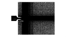
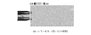
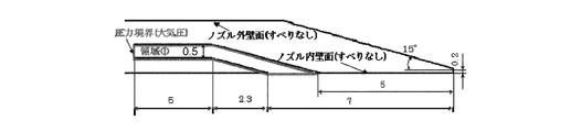
- FIGS. 11A to 11C schematically show two types of lattice models (hereinafter referred to as “circumferential model” and “axisymmetric model”) used in the calculation.
- 11A is an axisymmetric model diagram
- FIG. 11B is an all-around model diagram
- FIG. 11C is an enlarged view of the nozzle portion of the all-around model.
- the analysis region is assumed to be a flow field in which a jet is periodically ejected from a nozzle toward a wide space, and is set according to the experimental environment.
- the all-around model is a three-dimensional lattice model that faithfully reproduces the region to be analyzed, and the spatial resolution of the calculation lattice is set high in consideration of the implementation of turbulent flow analysis. This makes it possible to simulate in detail the behavior change from the formation of the vortex ring to the diffusion.
- the axis target model is a lattice model that uses only a quarter of the entire circumference model, and imposes periodic boundary conditions on the cut surface (equivalent to imposing axial symmetry conditions on the flow field). This makes it possible to analyze a three-dimensional flow field in a short time.
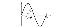
- the flow rate fluctuation waveform of the pulsating jet is a sine waveform shown in FIG.
- velocity amplitude V 0 and the period T represents the condition of the flow rate variation becomes forming conditions of vortex rings
- the notation conditions represented by the following formula using the diameter d n jets in addition to the V 0 and T Dimensionless parameters are used.
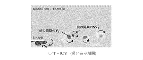
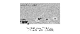
- FIGS. 13A to 13C are diagrams showing the formation process of a vortex ring in water using the dimensionless vorticity distribution (hereinafter referred to as “water vortex ring”), and the formation process of the vortex ring during one cycle of flow rate fluctuation.
- the phase change is shown using experimental results and calculation results from two lattice models.
- 13A is an experimental result diagram
- FIG. 13B is a result diagram based on an all-around model
- FIG. 13C is a result diagram based on an axisymmetric model.
- the contour in the figure shows the distribution of vorticity corresponding to the rotational angular velocity of the local region, and the arrows in the figure indicate the direction of rotation of the vortex, and the darker the gray color, the faster the rotation.
- the vortex ring S1 indicating the boundary layer formed on the wall surface in the nozzle is rolled up at the outlet of the nozzle during the jet discharge period. V1 is formed.
- the boundary layer S2 is formed on the inner wall surface of the nozzle by the suction flow, but this S2 eventually peels from the wall surface to form the separation vortex ring VS2.
- VS2 moves to the nozzle outlet and interferes with V1 being formed. From this, it can be predicted that the influence of VS2 on the strength of the vortex of V1 (circulation of the vortex ring) is very large.
- the strength of the vortex ring may be estimated to be weaker than actual, but the vortex ring formation process can be qualitatively evaluated, and the behavior and dimensions of the vortex ring can also be quantitatively evaluated. It was confirmed.
- the vortex ring that is optimal for transport has a large volume of vortex ring (the volume that stores the transported object) and a circulation that represents the strength of the vortex ring. It can be considered as a vortex ring with a large value (it takes time to diffuse). Therefore, the relationship between the volume and circulation of the vortex ring formed in the air (hereinafter referred to as “air vortex ring”) and the pulsation condition of the jet flow is clarified in order to clarify the formation condition of the vortex ring optimal for heat transport. It is necessary to clarify.
- the volume and circulation of the vortex ring are in a direct proportional relationship, and the circulation of the vortex ring is the Strouhal number Str of the pulsating jet (formula (2)). It is known that the circulation is maximized under the condition of Str ⁇ 0.05. If these experimental results are also valid for the formation process of the air vortex ring, that is, if hydrodynamic similarity is confirmed with respect to the formation of the vortex ring, all the knowledge obtained in the water vortex ring experiment is It can be applied to the air vortex ring.
- FIG. 15A shows the phase change of the air vortex ring under the pulsation condition of Condition A using a dimensionless vorticity distribution. In this CFD, an all-around model was used.
- FIG. 15B also shows a CFD result using an axisymmetric model of a water vortex ring under the same pulsation condition for comparison. From FIG. 15A and FIG. 15B, in the behavior change from formation to diffusion of the vortex ring V1 and the separation vortex ring VS2 used for transportation, both show very good agreement. In the VS2 diffusion process, the water vortex ring requires more time for diffusion, and there are slight differences in the cross-sectional shape of the vortex ring V1.
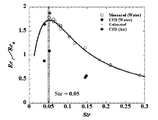
- FIG. 16 shows the results of experiments and CFD on the relationship between the dimensionless circulation of the vortex ring and the Strouhal number Str of the pulsating jet.
- Str the period of the amplitude Re 0 at the same value of the pulsation jets are different (i.e. Str different) vortex ring cyclic Re gamma Represents a change.
- the dimensionless circulation shows a smaller value than the experimental value in any of conditions A, B, and C.
- the CFD uses an axisymmetric model in this CFD, so that the separation vortex ring is less likely to diffuse than it actually is under all pulsation conditions.
- the time during which the separation vortex ring interferes with the vortex ring becomes longer and the circulation of the vortex ring becomes smaller.
- the rate of decrease of the dimensionless circulation value with respect to the experimental value is almost the same for all of the conditions A, B, and C, the rate of change of the dimensionless circulation with respect to Str agrees with the experimental result, and is obtained by experiment. It can be seen that the conditions under which the dimensionless circulation is maximized can also be confirmed by CFD using an axisymmetric model.
- the dimensionless circulation in the condition A shows a smaller value than the experimental value, which is almost the same value as in the case of the water vortex ring.
- the reason for this is the same as in the case of the CFD of the water vortex ring.
- the separation vortex ring is less likely to diffuse than the actual one, and thus the circulation of the vortex ring is considered to be small.
- the dimensionless circulation is greatly different from the result of the water vortex ring and shows almost the same value as the experimental value. The reason is considered as follows.
- FIG. 17A and 17B show the dimensionless vorticity distribution under condition B.
- FIG. 17A and 17B show the dimensionless vorticity distribution under condition B.
- FIG. 15 Under this pulsation condition, it can be confirmed that the length in the flow direction of the separation boundary layer S2 formed during the jet suction period is longer than that in the condition A (see FIG. 15) and extends in the upstream direction. In this way, when the separation boundary layer extends long, the vorticity layer is unlikely to gather in one region, so that the separation vortex ring VS2 having a large cross-sectional region as in Condition A is difficult to be formed.
- the separation vortex ring is in a state of being easily diffused, and further, since no axial symmetry condition is imposed in the calculation, the diffusion of the separation vortex ring further proceeds, and the influence of the separation vortex ring on the formation of the vortex ring is reduced. It is thought that the circulation of the vortex ring became larger.
- the trend of the change of dimensionless circulation with respect to Str is in agreement with the experimental result, and it can be seen that the dimensionless circulation of the air vortex ring is maximized under the condition of Str ⁇ 0.05 as in the case of the water vortex ring. This result also shows that hydrodynamic similarity is established in the circulation of the vortex ring (strength of the vortex ring).
- Method 1 When hot fluid is ejected as a pulsating jet (the simplest method) (not shown)
- Method 2 A method of heating the boundary layer by installing a heat source on the wall surface in the nozzle (see FIG. 18A).
- Method 3 A method of heating the boundary layer by installing a heat source on the inner and outer wall surfaces of the nozzle (see FIG. 18B).
- Method 4 A flow path having a width of 0.5 mm is provided on the wall surface in the nozzle, and the thermal fluid is naturally injected into the boundary layer (the movement of the thermal fluid is caused by the pressure difference caused by the flow around the flow path outlet. (See FIG. 18C.)
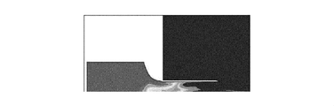
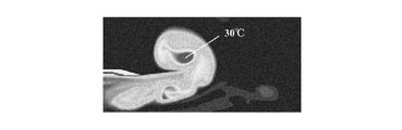
- FIGS. 19A to 19D the thermal fluid transport results in the four methods are shown using the temperature distribution.
- Method 1 conventional example
- FIG. 19A it can be seen that almost no thermal fluid is stored in the vortex ring, and that this method cannot perform concentrated transportation in the local space.
- the thermal fluid since the pulsation is started from the state where the entire nozzle is filled with hot water at 80 ° C., the thermal fluid is stored in the vortex ring in the first cycle of the pulsation, but from the second cycle onwards. Since the thermal fluid does not flow into the boundary layer, the thermal fluid is not stored in the vortex ring.
- the fluid in the boundary layer is heated by the heat source on the inner wall surface of the nozzle, so that hot water is stored in the vortex ring and intensive transport in the local space is possible.
- the temperature of the hot water in the vortex ring is only about 25 ° C. and about 31% of the temperature of the heating source even at the center of the vortex ring where the temperature is highest in the phase immediately after the formation of the vortex ring. I can't say that.
- the amount of heat stored in the vortex ring greatly depends on the heat transfer coefficient of the fluid, and is not suitable for air having a small heat transfer coefficient.
- FIG. 19E shows the temperature distribution of the thermal fluid when the thermal fluid is ejected at a constant flow rate as a reference (that is, a general ejection method), but the water temperature is separated from the nozzle by the flow mixing / diffusion effect. It can be seen that the concentrated transport in the local space as seen in the methods 2, 3 and 4 is not possible.
- Method 4 of naturally injecting the thermal fluid into the boundary layer from the flow path provided on the wall surface in the nozzle is the most effective method for storing the thermal fluid in the vortex ring. Moreover, although it was inferior to the method 4 about the method 2 and 3, the thermal fluid was stored in the vortex ring, and it was confirmed that it is effective compared with the method 1.
- FIG. 20 shows the relationship between the temperature of the center point of the vortex ring and the arrival position of the center point in each channel width. Looking at the results when the flow path width is 0.5 mm, the temperature at the center of the vortex ring, which was 40 ° C. at the time of formation of the vortex ring, suddenly dropped to 30 ° C. immediately after the vortex ring was separated from the nozzle. It can be confirmed that it has advanced rapidly. After this, diffusion proceeds slowly, but since the temperature in the vortex ring is not high at the start of transportation, the temperature is almost the same as the surrounding water temperature at the position where the reach distance is 4d (4 times the nozzle diameter d). It has become.
- the temperature at the center of the vortex ring is rapidly decreased immediately after the vortex ring is separated from the nozzle, and the diffusion of the thermal fluid has progressed rapidly.
- the temperature of the center point of the vortex ring is higher than in the case of 0.5 mm, and even when the reach distance is 4d.
- the temperature is maintained at 45 ° C. and about 56% of the heat source.
- the temperature of the center point of the vortex ring in this flow path width was 35.5 ° C.
- the temperature change at the center point of the vortex ring in the air vortex ring when the flow path width is 1.5 mm is about 35.5 ° C. (temperature drop 44.5 ° C.) at the position where the reach distance is 20d, and the reach distance is 40d.
- the position is estimated to be about 22.5 ° C. (temperature drop 57.5 ° C.).
- the fluid conveyance device and the fluid conveyance method of the present invention can be used in a wide space or in a closed space such as in a pipe line or a duct, and different kinds or similar kinds of liquids in the liquid filled in these spaces can be used. It can be used as a conveying means, as a conveying means for different or the same kind of gas in the gas, or as a conveying means for the gas in the liquid.
- (9) Use as an air curtain at the freezer entrance of the factory.
- (10) Use as a transport method for sending oxygen at the time of oxygen suction to the patient's mouth and nose without using an oxygen mask in a medical field.
- (11) Use as a transport method for sending anesthesia during anesthesia suction to a patient's mouth and nose without using a mask in a medical field.
- (12) Use as a transport method for sending warm air to a patient for the purpose of maintaining the body temperature of the patient during surgery in a medical field.
- (13) Use as a method of transporting oxygen to protect a doctor who is an operator from gas generated during surgery in a medical field.
- (14) Use as a transport method for sending oxygen to the patient's mouth and nose without using an oxygen mask in the oxygen supply of an emergency oxygen mask in an aircraft.
Landscapes
- Engineering & Computer Science (AREA)
- Mechanical Engineering (AREA)
- General Engineering & Computer Science (AREA)
- Chemical & Material Sciences (AREA)
- Combustion & Propulsion (AREA)
- Fluid Mechanics (AREA)
- Physics & Mathematics (AREA)
- Nozzles (AREA)
- Air Transport Of Granular Materials (AREA)
- Duct Arrangements (AREA)
- Air-Conditioning For Vehicles (AREA)
- Containers And Packaging Bodies Having A Special Means To Remove Contents (AREA)
- Jet Pumps And Other Pumps (AREA)
Abstract
Priority Applications (4)
| Application Number | Priority Date | Filing Date | Title |
|---|---|---|---|
| CN201380039544.2A CN104769367B (zh) | 2012-07-24 | 2013-06-13 | 流体搬运装置以及流体搬运方法 |
| JP2014526815A JP5846617B2 (ja) | 2012-07-24 | 2013-06-13 | 流体搬送装置および流体搬送方法 |
| KR1020157004571A KR20150063366A (ko) | 2012-07-24 | 2013-06-13 | 유체반송장치 및 유체반송방법 |
| US14/605,381 US9702384B2 (en) | 2012-07-24 | 2015-01-26 | Fluid transportation device and fluid transportation method |
Applications Claiming Priority (2)
| Application Number | Priority Date | Filing Date | Title |
|---|---|---|---|
| JP2012-163897 | 2012-07-24 | ||
| JP2012163897 | 2012-07-24 |
Related Child Applications (1)
| Application Number | Title | Priority Date | Filing Date |
|---|---|---|---|
| US14/605,381 Continuation US9702384B2 (en) | 2012-07-24 | 2015-01-26 | Fluid transportation device and fluid transportation method |
Publications (1)
| Publication Number | Publication Date |
|---|---|
| WO2014017208A1 true WO2014017208A1 (fr) | 2014-01-30 |
Family
ID=49997024
Family Applications (1)
| Application Number | Title | Priority Date | Filing Date |
|---|---|---|---|
| PCT/JP2013/066321 Ceased WO2014017208A1 (fr) | 2012-07-24 | 2013-06-13 | Dispositif de transport de fluide et procédé de transport de fluide |
Country Status (5)
| Country | Link |
|---|---|
| US (1) | US9702384B2 (fr) |
| JP (1) | JP5846617B2 (fr) |
| KR (1) | KR20150063366A (fr) |
| CN (1) | CN104769367B (fr) |
| WO (1) | WO2014017208A1 (fr) |
Cited By (8)
| Publication number | Priority date | Publication date | Assignee | Title |
|---|---|---|---|---|
| WO2019198571A1 (fr) * | 2018-04-11 | 2019-10-17 | 株式会社デンソー | Dispositif d'évacuation d'air |
| WO2020067190A1 (fr) * | 2018-09-28 | 2020-04-02 | ダイキン工業株式会社 | Dispositif de génération d'anneau tourbillon |
| JP2020051729A (ja) * | 2018-09-28 | 2020-04-02 | ダイキン工業株式会社 | 渦輪発生装置 |
| JP2020067265A (ja) * | 2018-04-11 | 2020-04-30 | 株式会社デンソー | 空気吹出装置 |
| JP2020104835A (ja) * | 2018-12-25 | 2020-07-09 | 株式会社Soken | 空気吹出装置 |
| WO2021153274A1 (fr) * | 2020-01-31 | 2021-08-05 | 株式会社デンソー | Dispositif de soufflage d'air |
| JP2022506482A (ja) * | 2018-11-02 | 2022-01-17 | ユニバーシティ・オブ・シンシナティ | 脈動気道陽圧デバイスおよび使用方法 |
| WO2022244419A1 (fr) | 2021-05-19 | 2022-11-24 | パナソニックIpマネジメント株式会社 | Système de commande d'écoulement d'air |
Families Citing this family (25)
| Publication number | Priority date | Publication date | Assignee | Title |
|---|---|---|---|---|
| GB201220471D0 (en) * | 2012-11-14 | 2012-12-26 | Technology Partnership The | Pump |
| WO2015181100A1 (fr) * | 2014-05-27 | 2015-12-03 | Oce-Technologies B.V. | Dispositif de feuilletage de feuilles assisté par tourbillon d'air |
| WO2017030078A1 (fr) * | 2015-08-19 | 2017-02-23 | 株式会社日本自動車部品総合研究所 | Dispositif de génération d'écoulement en jet, et système de génération d'écoulement en jet |
| CN106423698B (zh) * | 2016-10-31 | 2019-03-05 | 中国空气动力研究与发展中心高速空气动力研究所 | 一种基于涡环结构的雾化射流方法及其装置 |
| JP6638621B2 (ja) * | 2016-11-07 | 2020-01-29 | トヨタ自動車株式会社 | 空調用レジスタ |
| WO2019068171A1 (fr) * | 2017-10-06 | 2019-04-11 | Stitech Industries Inc. | Système de séparation de matières visqueuses de solides |
| WO2019109042A1 (fr) * | 2017-11-30 | 2019-06-06 | KOERNER, Michael R. | Systèmes d'application de compositions de revêtement utilisant un applicateur à efficacité de transfert élevée et procédés correspondants |
| DE112019001888B4 (de) | 2018-04-11 | 2022-06-09 | Denso Corporation | Luftausstoßvorrichtung |
| JP7255170B2 (ja) | 2018-04-11 | 2023-04-11 | 株式会社デンソー | 空気吹出装置 |
| CN108592367B (zh) * | 2018-05-22 | 2019-08-30 | 浙江大学 | 基于涡环原理的空调送风优化装置 |
| WO2020075854A1 (fr) * | 2018-10-12 | 2020-04-16 | ダイキン工業株式会社 | Dispositif d'évacuation d'air, dispositif de support de couchette et dispositif de notification de temps |
| CN109945288B (zh) * | 2019-03-29 | 2020-01-31 | 武汉理工大学 | 一种基于涡环低速循环送风的对流换热装置 |
| JP2021018018A (ja) * | 2019-07-19 | 2021-02-15 | 株式会社デンソー | 空気吹出装置 |
| CN112577107B (zh) * | 2019-09-30 | 2022-04-29 | 青岛海尔智能技术研发有限公司 | 空调器 |
| CN112747366A (zh) * | 2019-10-31 | 2021-05-04 | 广东美的制冷设备有限公司 | 涡环送出装置、空调室内机和空调器 |
| KR102324049B1 (ko) * | 2020-02-07 | 2021-11-08 | 일리노이즈 툴 워크스 인코포레이티드 | 디퓨전 기능을 갖는 에어벤트 |
| CN111412615B (zh) * | 2020-03-31 | 2022-03-11 | 广东美的制冷设备有限公司 | 基于空调器的涡环运动控制方法、空调、存储介质及装置 |
| CN111412605B (zh) * | 2020-03-31 | 2021-10-26 | 广东美的制冷设备有限公司 | 基于空调器的涡环生成方法、空调器、存储介质及装置 |
| CN111412606B (zh) * | 2020-03-31 | 2021-10-26 | 广东美的制冷设备有限公司 | 基于空调器的涡环生成方法、空调器、存储介质及装置 |
| CN111594920A (zh) * | 2020-05-29 | 2020-08-28 | 佛山市万物互联科技有限公司 | 空调室内机和空调 |
| CN111609465B (zh) * | 2020-05-29 | 2022-04-15 | 佛山市万物互联科技有限公司 | 空调的控制方法、空调及计算机可读存储介质 |
| CN111609471B (zh) * | 2020-05-29 | 2022-04-15 | 佛山市万物互联科技有限公司 | 涡环发生装置运行控制方法、空调及计算机可读存储介质 |
| CN112212443B (zh) * | 2020-10-27 | 2024-02-02 | 西安建筑科技大学 | 一种带环形风口的送风装置及其设计方法 |
| WO2023095549A1 (fr) | 2021-11-26 | 2023-06-01 | パナソニックIpマネジメント株式会社 | Soufflante d'écoulement d'air |
| CN113893631A (zh) * | 2021-12-13 | 2022-01-07 | 星诺大气环境科技(天津)有限公司 | 一种降低团雾浓度的方法 |
Citations (6)
| Publication number | Priority date | Publication date | Assignee | Title |
|---|---|---|---|---|
| JPS63150500A (ja) * | 1986-12-12 | 1988-06-23 | Res Dev Corp Of Japan | 二重筒コアンダスパイラルフロ−装置 |
| JPS63163000U (fr) * | 1987-04-10 | 1988-10-25 | ||
| JP2000176339A (ja) * | 1998-12-14 | 2000-06-27 | Mitsubishi Electric Corp | 流体搬送装置、この流体搬送装置を用いた加湿装置、空気調和装置、空気調和システム、及びこの加湿装置を用いた装飾装置 |
| JP2005016412A (ja) * | 2003-06-26 | 2005-01-20 | Jfe Engineering Kk | エジェクタおよび冷凍システム |
| JP2009186127A (ja) * | 2008-02-08 | 2009-08-20 | Takasago Thermal Eng Co Ltd | 清浄空気循環システム、及び清浄空気循環方法 |
| JP2012097733A (ja) * | 2010-10-08 | 2012-05-24 | Calsonic Kansei Corp | ジェットポンプおよび空調装置 |
Family Cites Families (19)
| Publication number | Priority date | Publication date | Assignee | Title |
|---|---|---|---|---|
| US2910830A (en) * | 1955-12-21 | 1959-11-03 | Gen Electric | Fluid flow apparatus |
| US3186329A (en) * | 1962-05-21 | 1965-06-01 | Barber Colman Co | Tubular air diffuser |
| US3396738A (en) * | 1964-11-27 | 1968-08-13 | American Standard Inc | Fluid guiding method and apparatus |
| US3229461A (en) * | 1965-05-04 | 1966-01-18 | Burton A Jones | Fluid amplification device for propulsion system roll control |
| JPH0647997B2 (ja) | 1986-12-26 | 1994-06-22 | 光洋精工株式会社 | 水ポンプ用軸受装置 |
| JP2934268B2 (ja) * | 1989-12-28 | 1999-08-16 | フクビ化学工業株式会社 | 粉体の表面被覆方法とその装置 |
| DE60219345T2 (de) * | 2001-12-07 | 2007-12-20 | Anderson, Jack, Calabassas | Strahldüsenmischer |
| US7243678B2 (en) * | 2004-01-27 | 2007-07-17 | Dayco Products, Llc | Fuel fill system with fuel vapor recirculation |
| CN101027494A (zh) * | 2004-07-29 | 2007-08-29 | 推进动力公司 | 喷射泵 |
| JP2008275196A (ja) * | 2007-04-25 | 2008-11-13 | Fuji Heavy Ind Ltd | 空気砲 |
| US8479878B2 (en) * | 2008-09-25 | 2013-07-09 | Parallaxial Innovation LLC | Channeling gas flow tube |
| US8807458B2 (en) * | 2009-04-29 | 2014-08-19 | King Saud University | Vortex-generating nozzle-end ring |
| CN101624819B (zh) * | 2009-07-28 | 2010-12-29 | 四川大学 | 双涡室掺气型漩流竖井 |
| US20110039491A1 (en) * | 2009-08-17 | 2011-02-17 | Syracuse University | Low Mixing Ventilation Jet |
| CN102444626A (zh) * | 2010-10-08 | 2012-05-09 | 康奈可关精株式会社 | 喷射泵及空调装置 |
| US20120160357A1 (en) * | 2010-12-22 | 2012-06-28 | Vis, Llc | Vortex ring generator |
| JP2012163897A (ja) | 2011-02-09 | 2012-08-30 | Seiko Epson Corp | 液晶駆動方法、液晶駆動装置、液晶装置、及び電子機器 |
| DE102011076456A1 (de) * | 2011-05-25 | 2012-11-29 | Siemens Aktiengesellschaft | Vorrichtung zum Mischen eines ersten und eines zweiten Medienstroms eines Strömungsmediums |
| US20130214054A1 (en) * | 2012-02-09 | 2013-08-22 | Battelle Memorial Institute | Generator apparatus for producing vortex rings entrained with charged particles |
-
2013
- 2013-06-13 JP JP2014526815A patent/JP5846617B2/ja active Active
- 2013-06-13 CN CN201380039544.2A patent/CN104769367B/zh not_active Expired - Fee Related
- 2013-06-13 KR KR1020157004571A patent/KR20150063366A/ko not_active Withdrawn
- 2013-06-13 WO PCT/JP2013/066321 patent/WO2014017208A1/fr not_active Ceased
-
2015
- 2015-01-26 US US14/605,381 patent/US9702384B2/en not_active Expired - Fee Related
Patent Citations (6)
| Publication number | Priority date | Publication date | Assignee | Title |
|---|---|---|---|---|
| JPS63150500A (ja) * | 1986-12-12 | 1988-06-23 | Res Dev Corp Of Japan | 二重筒コアンダスパイラルフロ−装置 |
| JPS63163000U (fr) * | 1987-04-10 | 1988-10-25 | ||
| JP2000176339A (ja) * | 1998-12-14 | 2000-06-27 | Mitsubishi Electric Corp | 流体搬送装置、この流体搬送装置を用いた加湿装置、空気調和装置、空気調和システム、及びこの加湿装置を用いた装飾装置 |
| JP2005016412A (ja) * | 2003-06-26 | 2005-01-20 | Jfe Engineering Kk | エジェクタおよび冷凍システム |
| JP2009186127A (ja) * | 2008-02-08 | 2009-08-20 | Takasago Thermal Eng Co Ltd | 清浄空気循環システム、及び清浄空気循環方法 |
| JP2012097733A (ja) * | 2010-10-08 | 2012-05-24 | Calsonic Kansei Corp | ジェットポンプおよび空調装置 |
Cited By (20)
| Publication number | Priority date | Publication date | Assignee | Title |
|---|---|---|---|---|
| WO2019198571A1 (fr) * | 2018-04-11 | 2019-10-17 | 株式会社デンソー | Dispositif d'évacuation d'air |
| JP2020067265A (ja) * | 2018-04-11 | 2020-04-30 | 株式会社デンソー | 空気吹出装置 |
| US11718157B2 (en) | 2018-04-11 | 2023-08-08 | Denso Corporation | Air discharge device |
| WO2020067190A1 (fr) * | 2018-09-28 | 2020-04-02 | ダイキン工業株式会社 | Dispositif de génération d'anneau tourbillon |
| JP2020051729A (ja) * | 2018-09-28 | 2020-04-02 | ダイキン工業株式会社 | 渦輪発生装置 |
| JP2020049476A (ja) * | 2018-09-28 | 2020-04-02 | ダイキン工業株式会社 | 渦輪発生装置 |
| WO2020067151A1 (fr) * | 2018-09-28 | 2020-04-02 | ダイキン工業株式会社 | Dispositif de production d'anneau tourbillonnaire |
| CN112789454A (zh) * | 2018-09-28 | 2021-05-11 | 大金工业株式会社 | 涡环产生装置 |
| US11333178B2 (en) | 2018-09-28 | 2022-05-17 | Daikin Industries, Ltd. | Vortex ring generation device |
| EP3832222A4 (fr) * | 2018-09-28 | 2022-04-20 | Daikin Industries, Ltd. | Dispositif de génération d'anneau tourbillon |
| JP2022506482A (ja) * | 2018-11-02 | 2022-01-17 | ユニバーシティ・オブ・シンシナティ | 脈動気道陽圧デバイスおよび使用方法 |
| JP2024097060A (ja) * | 2018-11-02 | 2024-07-17 | ユニバーシティ・オブ・シンシナティ | 脈動気道陽圧デバイスおよび使用方法 |
| US12214139B2 (en) | 2018-11-02 | 2025-02-04 | University Of Cincinnati | Pulsating positive airway pressure devices and methods of use |
| JP7825300B2 (ja) | 2018-11-02 | 2026-03-06 | ユニバーシティ・オブ・シンシナティ | 脈動気道陽圧デバイスおよび使用方法 |
| CN113226816A (zh) * | 2018-12-25 | 2021-08-06 | 株式会社电装 | 空气吹出装置 |
| JP2020104835A (ja) * | 2018-12-25 | 2020-07-09 | 株式会社Soken | 空気吹出装置 |
| US11945285B2 (en) | 2018-12-25 | 2024-04-02 | Denso Corporation | Air discharge device |
| CN113226816B (zh) * | 2018-12-25 | 2024-08-16 | 株式会社电装 | 空气吹出装置 |
| WO2021153274A1 (fr) * | 2020-01-31 | 2021-08-05 | 株式会社デンソー | Dispositif de soufflage d'air |
| WO2022244419A1 (fr) | 2021-05-19 | 2022-11-24 | パナソニックIpマネジメント株式会社 | Système de commande d'écoulement d'air |
Also Published As
| Publication number | Publication date |
|---|---|
| JP5846617B2 (ja) | 2016-01-20 |
| CN104769367A (zh) | 2015-07-08 |
| JPWO2014017208A1 (ja) | 2016-07-07 |
| US20150300385A1 (en) | 2015-10-22 |
| US9702384B2 (en) | 2017-07-11 |
| KR20150063366A (ko) | 2015-06-09 |
| CN104769367B (zh) | 2017-10-13 |
Similar Documents
| Publication | Publication Date | Title |
|---|---|---|
| JP5846617B2 (ja) | 流体搬送装置および流体搬送方法 | |
| US20230347364A1 (en) | Apparatus for nanoparticle generation | |
| US9216429B2 (en) | Mist generating apparatus and method | |
| JP2024500077A5 (fr) | ||
| JP2016535835A5 (fr) | ||
| JP2019509894A5 (fr) | ||
| EP3259543B1 (fr) | Appareil et procédé permettant de générer des gouttelettes | |
| PL2190587T3 (pl) | Dysza wielootworowa lub wiązkowa | |
| JP2012504431A5 (fr) | ||
| WO2013141695A8 (fr) | Appareil et procédé de production en masse d'un agent de microbulles monodispersées | |
| CN102834168A (zh) | 用于将次生流体喷入初生流体里的喷雾系统和方法 | |
| ES2948235T3 (es) | Aparatos y procesos de secado por pulverización de ultra alta eficiencia | |
| JP5975976B2 (ja) | シーディング装置 | |
| CN110402167B (zh) | 喷枪、燃烧设备和用于处理排气的方法 | |
| EP1901858B1 (fr) | Procede de nettoyage de lumiere | |
| JP4239879B2 (ja) | マイクロミスト発生方法及びその装置 | |
| JP2014124599A (ja) | セメントプラントの脱硝装置及びそれを備えるセメントプラント | |
| CN103112914A (zh) | 一种机械喷射高效消除泡沫装置 | |
| JP2005515883A (ja) | 混合装置 | |
| KR20110038026A (ko) | 운반 가스의 고형물을 가스 스트림으로 전달하기 위한 시스템 및 방법 | |
| ATE491377T1 (de) | Vorrichtung und verfahren zur zubereitung einer zum menschlichen verzehr geeigneten geschäumten flüssigkeit | |
| CN104152931B (zh) | 一种旋流式不锈钢酸洗系统及其方法 | |
| RU124891U1 (ru) | Насадок для пожаротушения | |
| CN201969509U (zh) | 一种用于药剂或水体混合的装置 | |
| JP2008023459A (ja) | 二流体噴射ノズル |
Legal Events
| Date | Code | Title | Description |
|---|---|---|---|
| 121 | Ep: the epo has been informed by wipo that ep was designated in this application |
Ref document number: 13822475 Country of ref document: EP Kind code of ref document: A1 |
|
| ENP | Entry into the national phase |
Ref document number: 2014526815 Country of ref document: JP Kind code of ref document: A |
|
| NENP | Non-entry into the national phase |
Ref country code: DE |
|
| ENP | Entry into the national phase |
Ref document number: 20157004571 Country of ref document: KR Kind code of ref document: A |
|
| 122 | Ep: pct application non-entry in european phase |
Ref document number: 13822475 Country of ref document: EP Kind code of ref document: A1 |