WO2014017548A1 - ワイヤハーネス用外装部材及びワイヤハーネス - Google Patents
ワイヤハーネス用外装部材及びワイヤハーネス Download PDFInfo
- Publication number
- WO2014017548A1 WO2014017548A1 PCT/JP2013/070074 JP2013070074W WO2014017548A1 WO 2014017548 A1 WO2014017548 A1 WO 2014017548A1 JP 2013070074 W JP2013070074 W JP 2013070074W WO 2014017548 A1 WO2014017548 A1 WO 2014017548A1
- Authority
- WO
- WIPO (PCT)
- Prior art keywords
- exterior member
- wire harness
- attachment
- wire
- clamp
- Prior art date
- Legal status (The legal status is an assumption and is not a legal conclusion. Google has not performed a legal analysis and makes no representation as to the accuracy of the status listed.)
- Ceased
Links
Images






Classifications
-
- B—PERFORMING OPERATIONS; TRANSPORTING
- B60—VEHICLES IN GENERAL
- B60R—VEHICLES, VEHICLE FITTINGS, OR VEHICLE PARTS, NOT OTHERWISE PROVIDED FOR
- B60R16/00—Electric or fluid circuits specially adapted for vehicles and not otherwise provided for; Arrangement of elements of electric or fluid circuits specially adapted for vehicles and not otherwise provided for
- B60R16/02—Electric or fluid circuits specially adapted for vehicles and not otherwise provided for; Arrangement of elements of electric or fluid circuits specially adapted for vehicles and not otherwise provided for electric constitutive elements
- B60R16/0207—Wire harnesses
- B60R16/0215—Protecting, fastening and routing means therefor
-
- H—ELECTRICITY
- H02—GENERATION; CONVERSION OR DISTRIBUTION OF ELECTRIC POWER
- H02G—INSTALLATION OF ELECTRIC CABLES OR LINES, OR OF COMBINED OPTICAL AND ELECTRIC CABLES OR LINES
- H02G3/00—Installations of electric cables or lines or protective tubing therefor in or on buildings, equivalent structures or vehicles
- H02G3/02—Details
- H02G3/04—Protective tubing or conduits, e.g. cable ladders or cable troughs
- H02G3/0406—Details thereof
- H02G3/0418—Covers or lids; Their fastenings
-
- H—ELECTRICITY
- H02—GENERATION; CONVERSION OR DISTRIBUTION OF ELECTRIC POWER
- H02G—INSTALLATION OF ELECTRIC CABLES OR LINES, OR OF COMBINED OPTICAL AND ELECTRIC CABLES OR LINES
- H02G3/00—Installations of electric cables or lines or protective tubing therefor in or on buildings, equivalent structures or vehicles
- H02G3/02—Details
- H02G3/04—Protective tubing or conduits, e.g. cable ladders or cable troughs
- H02G3/0462—Tubings, i.e. having a closed section
- H02G3/0468—Corrugated
-
- H—ELECTRICITY
- H02—GENERATION; CONVERSION OR DISTRIBUTION OF ELECTRIC POWER
- H02G—INSTALLATION OF ELECTRIC CABLES OR LINES, OR OF COMBINED OPTICAL AND ELECTRIC CABLES OR LINES
- H02G3/00—Installations of electric cables or lines or protective tubing therefor in or on buildings, equivalent structures or vehicles
- H02G3/02—Details
- H02G3/04—Protective tubing or conduits, e.g. cable ladders or cable troughs
- H02G3/0462—Tubings, i.e. having a closed section
- H02G3/0481—Tubings, i.e. having a closed section with a circular cross-section
-
- H—ELECTRICITY
- H02—GENERATION; CONVERSION OR DISTRIBUTION OF ELECTRIC POWER
- H02G—INSTALLATION OF ELECTRIC CABLES OR LINES, OR OF COMBINED OPTICAL AND ELECTRIC CABLES OR LINES
- H02G1/00—Methods or apparatus specially adapted for installing, maintaining, repairing or dismantling electric cables or lines
- H02G1/14—Methods or apparatus specially adapted for installing, maintaining, repairing or dismantling electric cables or lines for joining or terminating cables
- H02G1/145—Moulds
-
- H—ELECTRICITY
- H02—GENERATION; CONVERSION OR DISTRIBUTION OF ELECTRIC POWER
- H02G—INSTALLATION OF ELECTRIC CABLES OR LINES, OR OF COMBINED OPTICAL AND ELECTRIC CABLES OR LINES
- H02G3/00—Installations of electric cables or lines or protective tubing therefor in or on buildings, equivalent structures or vehicles
- H02G3/30—Installations of cables or lines on walls, floors or ceilings
- H02G3/32—Installations of cables or lines on walls, floors or ceilings using mounting clamps
Definitions
- the present invention relates to an exterior member for a wire harness and a wire harness including the exterior member.
- a battery of a hybrid vehicle or an electric vehicle and an inverter unit are electrically connected by a high-voltage (ie, high-voltage) wire harness.
- the wire harness includes a high-voltage electric wire serving as a high-voltage conductive path and an exterior member that accommodates the high-voltage electric wire.
- a metal pipe is adopted as an exterior member.
- the said exterior member is fixed to the predetermined position of a vehicle body by the clamp fitted to the outer peripheral surface.
- the present invention has been made in view of the above circumstances, and an object thereof is to provide a wire harness exterior member and a wire harness capable of improving workability, reducing jigs, and the like.
- the wire harness exterior member according to the present invention is characterized by the following (1) to (8).
- An exterior member for a wire harness that covers a conductive path On the outer surface of the wire harness exterior member, there is a determining portion for the attachment position of a retrofit component attached to the wire harness exterior member.
- the wire harness exterior member of (1) above is a resin tube, and is provided with a mark portion as the determining portion during resin molding.
- the wire harness exterior member of (1) above, The said exterior member for wire harnesses is a resin-made pipe body, and the attaching part is integrally formed as said determination part at the time of resin molding.
- the wire harness exterior member of (3) above, The attachment portion includes a portion extending in at least one of the circumferential direction of the outer surface and the tube body axial direction.
- the wire harness exterior member includes a convex portion or a ridge-shaped portion protruding from the outer surface.
- the wire harness exterior member according to any one of (1) to (5) above,
- the exterior member for a wire harness has a bent tube portion formed as a bent portion and a non-bend tube portion formed as a portion that is difficult to bend, and is formed into a substantially linear shape as a whole, and the non-bend tube The attachment portion is formed in the portion.
- the wire harness according to the present invention is characterized by the following points. (7)
- the wire harness exterior member of (1) above since it is an exterior member having an attachment position determination portion on the outer surface, the attachment position relative to the retrofitted component can be easily identified by the attachment position determination portion. Therefore, it is not necessary to manually determine the attachment position, which has been conventionally performed. In addition, a manual jig is not required, so that a dedicated jig is not required. Therefore, according to the wire harness exterior member (1) above, it is possible to improve workability and reduce the number of jigs compared to the conventional case.
- the exterior member is made of a resin tube and the mark portion is provided, the manual determination work related to the attachment position, which has been conventionally performed, becomes unnecessary.
- the manual determination of the mounting position is not required, and a dedicated jig is not required.
- the attachment position can be identified without increasing the number of components. Therefore, it is not necessary to manually determine the attachment position, which has been conventionally performed. Moreover, if the determination work of the attachment position by manual work becomes unnecessary, a dedicated jig will become unnecessary.
- the wire harness exterior member of the above (4) since the attachment portion including the portion extending in at least one of the circumferential direction of the outer surface and the tube axis direction is formed, the work man-hours and the number of parts are not increased. In addition, it is possible to prevent positional displacement of the retrofitted parts.
- a mounting portion including a convex portion or a ridge-shaped portion protruding from the outer surface is formed.
- the convex portion or the ridge shape portion functions as a portion that ensures chipping resistance.
- the wire harness exterior member of (5) above the necessary and sufficient rigidity can be obtained even if the wall thickness of the tube body is reduced by forming the attachment portion in the shape of a protrusion extending in the tube axis direction. It can be secured on the mounting side.
- the attachment part is formed to protrude in the circumferential direction of the outer surface of the tubular body, for example, at a predetermined interval, thereby associating the retrofitting part with this rotational direction That is, the mounting portion functions as a detent.
- the wire harness exterior member (6) since the whole is formed in a substantially linear shape, it is possible to automate the manufacturing process of the wire harness. If automation can be achieved, manpower can be reduced. Moreover, according to the exterior member for wire harnesses of the above (6), since it has a structure having a bent tube portion and a non-bent tube portion, if the bent tube portion is arranged in a portion that needs to be bent, for example, at the time of transportation When a bend is required, such as when routing a route, a state in which the whole is substantially straight can be changed to a state in which a portion is bent immediately. Further, according to the wire harness exterior member (6) described above, the attachment portion is formed at a portion that is difficult to bend, so the position of the attachment portion is stabilized. Thereby, workability
- the wire harness of the above (7) since it includes any one of the wire harness exterior members of (1) to (6), it is lightweight and has good workability for attaching the retrofitting parts, and further inexpensive. Thus, it is possible to provide a wire harness having good chipping resistance.
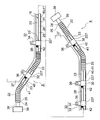
- FIG. 1 is a mimetic diagram showing the wiring state of a wire harness.
- FIG. 2 is a perspective view showing the configuration of the wire harness.
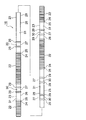
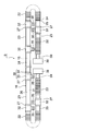
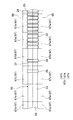
- FIG. 3 is a configuration diagram of the exterior member of the first embodiment.
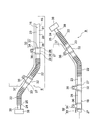
- FIG. 4 is a diagram illustrating a wire harness during route routing.
- FIG. 5 is a diagram showing a wire harness during transportation.
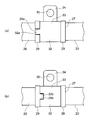
- 6 (a) and 6 (b) are diagrams showing a modification of the attaching portion and the clamp in FIG.
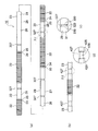
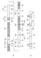
- Fig.7 (a) and FIG.7 (b) are figures which show the exterior member of 2nd Embodiment.
- 8 (a) to 8 (c) are views showing the exterior member of the third embodiment, and
- FIG. 8 (c) is an enlarged view of a VIIIc portion of FIG. 8 (a).
- FIG. 9 is a view showing a modified example of the clamp when the attaching portion of FIG. 8 is adopted.
- 10 (a) to 10 (d) are views showing the exterior member of the fourth embodiment.
- FIG. 10 (c) is an enlarged view of the portion Xc in FIG. 10 (a), and FIG. 10 (d).
- FIG. 11 is an enlarged view of a portion Xd in FIG.
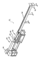
- FIG. 11 is a perspective view showing an exterior member manufacturing apparatus.
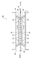
- FIG. 12 is a plan view showing a main part of the manufacturing apparatus of FIG.
- FIG. 13 is a plan view showing an arrangement state of the mold block and the exterior member of FIG. 14 (a) to 14 (c) are cross-sectional views showing the mold block of FIG.
- FIG. 15A to FIG. 15C are configuration diagrams of an exterior member according to the fifth embodiment.
- FIG. 16A and FIG. 16B are configuration diagrams of the exterior member of the sixth embodiment.
- the wire harness according to the present embodiment includes at least one conductive path and an exterior member that is a resin tube covering the conductive path.
- the exterior member is integrally formed with an attachment portion for a retrofit component on the outer surface thereof.
- the attachment portion is formed to extend in at least one of the circumferential direction of the outer surface of the exterior member and the tube axis direction.
- the attachment portion has functions such as prevention of positional deviation and prevention of rotation with respect to the retrofitted parts.
- the exterior member may be provided with a mark portion instead of the attachment portion.
- the mark part is a part for determining the attachment position with respect to the retrofitted component.
- FIG. 1 is a schematic diagram showing a wiring harness wiring state.
- 2 is a perspective view showing the configuration of the wire harness
- FIG. 3 is a configuration diagram of the exterior member of the first embodiment
- FIG. 4 is a diagram showing the wire harness during route routing
- FIG. 5 is the wire harness during transportation.
- FIGS. 6 (a) and 6 (b) are diagrams showing a modification of the mounting portion and the clamp.
- the wire harness including the wire harness exterior member of the first embodiment is routed to a hybrid vehicle (which may be an electric vehicle or a general vehicle).
- a hybrid vehicle which may be an electric vehicle or a general vehicle.
- reference numeral 1 indicates a hybrid vehicle.
- the hybrid vehicle 1 is a vehicle that mixes and drives the two powers of the engine 2 and the motor unit 3. Electric power from a battery 5 (in other words, a battery pack) is supplied to the motor unit 3 via the inverter unit 4.
- a battery 5 in other words, a battery pack
- the engine 2, the motor unit 3, and the inverter unit 4 are mounted in an engine room 6 at a position close to the front wheels and the like.
- the battery 5 is mounted on the rear part 7 of the automobile close to the rear wheels.
- the battery 5 may be mounted in an automobile room that exists behind the engine room 6.
- the motor unit 3 and the inverter unit 4 are electrically connected by a high-voltage wire harness 8.
- the battery 5 and the inverter unit 4 are also electrically connected by a high-voltage wire harness 9.
- the intermediate portion 10 of the wire harness 9 is routed under the vehicle floor 11. Further, the wire harness 9 is routed substantially parallel along the vehicle floor 11.
- the vehicle underfloor 11 is a known body and a so-called panel member, and a through hole (not shown) is formed at a predetermined position. The wire harness 9 is inserted through the through hole.
- the wire harness 9 and the battery 5 are electrically connected via a junction block 12 provided in the battery 5.
- the rear end 13 of the wire harness 9 is electrically connected to the junction block 12 by a known method.
- the front end 14 side of the wire harness 9 is electrically connected to the inverter unit 4 by a known method.
- the motor unit 3 has a motor (not shown) and a generator (not shown).
- the inverter unit 4 includes an inverter (not shown) and a converter (not shown).
- the motor unit 3 is formed as a motor assembly including a shield case (not shown).
- the inverter unit 4 is also formed as an inverter assembly including a shield case (not shown).
- the battery 5 is of Ni-MH type or Li-ion type and is modularized. It is also possible to use a power storage device such as a capacitor.
- the battery 5 is not particularly limited as long as it can be used for the hybrid vehicle 1 and the electric vehicle.
- the wire harness 9 is a high-voltage member for electrically connecting the inverter unit 4 and the battery 5 as described above, and includes a high-voltage coaxial composite conductive path 15 (that is, a conductive path) and an exterior member 16 ( That is, it is comprised including the exterior member for wire harnesses.
- the wire harness 9 having such a configuration is attached to the vehicle underfloor 11 or the like via a clamp 32 (described later) which is a retrofit component.
- “High voltage” means for high voltage use.
- the single high-voltage coaxial composite conductive path 15 has a plus circuit and a minus circuit. That is, the high-voltage coaxial composite conductive path 15 has two systems. Specifically, the high-voltage coaxial composite conductive path 15 covers the first conductive path 17 having a circular cross section located at the center of the high-voltage coaxial composite conductive path 15 and the outer periphery of the first conductive path 17 with a predetermined thickness. A first insulator 18.
- the high-voltage coaxial composite conductive path 15 includes a second conductive path 19 provided outside the first insulator 18 and a second insulator 20 that covers the outer periphery of the second conductive path 19 with a predetermined thickness. Have.
- the high-voltage coaxial composite conductive path 15 further includes a cylindrical electromagnetic shield member 21 that is in close contact with the outer surface of the second insulator 20.
- the high-voltage coaxial composite conductive path 15 may further include a sheath that covers the outer periphery of the electromagnetic shield member 21 with a predetermined thickness.
- the electromagnetic shield member 21 is made of a known braid, metal foil, or the like, and may be arranged as follows in addition to the arrangement included in the configuration of the high-voltage coaxial composite conductive path 15 as described above. In other words, the electromagnetic shield member 21 may be arranged so as to be somewhat buzzed with respect to the second insulator 20.
- the electromagnetic shield member 21 may be formed in a cylindrical shape and adhered to the outer surface of the second insulator 20, or may be formed in a tape shape or a sheet shape and wound around the outer surface of the second insulator 20 to be adhered. Good.
- the high-voltage coaxial composite conductive path 15 has two systems in the present embodiment, but is not limited to this, and may be three systems, n systems. In other words, if the number of circuits is increased outward so that a single configuration is formed on the same axis, there are n systems.
- the exterior member 16 is a tube body that accommodates and protects the high-voltage coaxial composite conductive path 15, and includes a bent tube portion 22 and a non-bend tube portion 23.
- the resin is molded so as to be substantially linear.
- the bent pipe portion 22 is a bent portion that is bent when the wire harness 9 is transported or routed, and the non-bent pipe portion 23 is continuous with the bent pipe portion 22.
- the non-bending tube portion 23 is provided as a portion that does not bend (in other words, is difficult to bend).
- the bending pipe part 22 and the non-bending pipe part 23 are respectively arranged and formed at positions and lengths according to the vehicle mounting shape.
- bending pipe part 22 and the non-bending pipe part 23 are each formed in multiple numbers in this Example, at least one should just be formed and the number is not specifically limited.
- the bending tube portion 22 is formed in a bellows tube shape having a plurality of concave portions 24 and convex portions 25 continuously formed in the circumferential direction of the outer surface in the longitudinal direction.
- the length of the bending pipe portion 22 is set according to the bending range.
- the bending tube portion 22 is formed in a bendable portion having flexibility (in other words, flexibility).
- the bending pipe part 22 is formed in the same part as a well-known corrugated tube in 1st Embodiment.
- the shape of the bending pipe part 22 is a shape which can be bent, it will not be limited to the said bellows pipe shape.
- the exterior member 16 has the same shape as the corrugated tube as described above, it can be regarded as a “cortube” or a “partially formed corrugated tube”.
- the exterior member 16 is formed in a shape in which no slit is provided (that is, there is no stomach split) along the tube axis direction (that is, the longitudinal direction).
- the reason why the slit is not provided is that water is prevented from entering the exterior member 16 to improve waterproofness. Moreover, the point which ensures the intensity
- the non-bending pipe part 23 has a non-bending pipe part main body 26 and an attachment part 27 (that is, a determination part of an attachment position).
- the non-bending tube portion main body 26 is formed as a portion that does not bend during transportation or route routing as described above.
- the portion that does not bend means a portion that does not actively have flexibility.
- the non-bending tube portion body 26 is formed in a straight tube shape having a circular cross section.
- the shape of the non-bending tube portion main body 26 is not limited to a circular cross section, and may be an ellipse, an oval, or a quadrangle.
- the non-bending pipe part 23 can be regarded as a “straight pipe part” or a “straight part” because the non-bending pipe part body 26 has a straight tube shape.
- the non-bending tube portion main body 26 is formed thin so as to have a necessary minimum strength.
- rigidity may fall when it forms in thin wall, this fall can be supplemented with the rigidity of the attaching part 27.
- the exterior member 16 has a non-bending pipe portion 28 for the underfloor that is routed in the vehicle underfloor 11 (see FIGS. 1 and 4) as the non-bending pipe portion 23.
- the under-bending pipe portion 28 for underfloor is formed in a long shape because it is routed in the vehicle underfloor 11 (for example, routed along the lean hose).
- the underfloor non-bending tube portion 28 is one of the non-bending tube portions 23, and the underfloor non-bending tube portion 28 is also provided with a plurality of attachment portions 27.
- the mounting portion 27 is provided integrally with the non-bending tube portion main body 26 as a portion for mounting a later-described retrofit component (that is, the clamp 32). More specifically, the attachment portion 27 is integrally formed with the non-bending tube portion main body 26.
- the mounting portion 27 is easily integrated because the exterior member 16 is made of resin.
- the attachment portion 27 is provided at a portion where the clamp 32 needs to be attached. Therefore, some non-bending tube portions 23 may not have the attachment portion 27.
- the attachment part 27 includes a pair of movement restriction parts 29 and an attachment / detachment part 30.
- a pair of movement control part 29 is formed in the position corresponding to the both sides of the clamp 32 mentioned later.
- the pair of movement restricting portions 29 restrict the movement of the clamp 32 in the tube axis direction of the non-bending tube portion main body 26.
- the pair of movement restricting portions 29 are also used for recognizing the attachment position of the clamp 32.
- the pair of movement restricting portions 29 are formed in an annular flange shape in the present embodiment. Specifically, it protrudes from the outer surface 31 of the non-bending tube portion main body 26 and is formed in a convex shape over the entire circumference. This shape is an example. Other shapes will be described in second to fourth embodiments described later.
- the pair of movement restricting portions 29 have the protruding height and the width of the exterior member 16 in the tube axis direction that match the protruding height and width of the convex portion 25 in the bent tube portion 22.
- This dimensional design is an example.
- the attaching / detaching portion 30 is formed as a portion for attaching a clamp 32 described later.
- the outer surface 31 of the non-bending tube portion main body 26 existing between the pair of movement restricting portions 29 corresponds to this, and is formed into a curved surface.
- a detent structure shown in FIG. 6 described later is also effective.
- a known clamp 32 is attached to the attachment portion 27.
- the clamp 32 has a tubular body attachment portion 33 formed in accordance with the external shape of the non-bending tube portion 23 (that is, the external shape of the detachable portion 30), and a cantilever-shaped fixing continuous to the tubular body attachment portion 33. Part 34.
- a bolt insertion hole 35 (see FIG. 5) is formed through the fixing portion 34.
- the wire harness 9 is fixed to a fixed object 37 such as the vehicle underfloor 11 via a bolt 36 inserted into the bolt insertion hole 35.
- the shape of the fixed object 37 is an example.
- a clip, a grommet, a protector, etc. are mentioned. That is, instead of the clamp 32, these may be retrofitted parts.
- a known shield connector 38 is provided at each end of the wire harness 9.
- One shield connector 38 is a shield connector on the inverter side, and the other shield connector 38 is a shield connector on the battery side.
- the shield connector 38 is connected to a terminal 39 of the high-voltage coaxial composite conductive path 15 drawn out from the bending tube portion 22.
- the high-voltage coaxial composite conductive path 15 is inserted through the exterior member 16 that is formed in a substantially linear shape as a whole. Thereafter, the shield connector 38 is connected to both terminals 39 of the high-voltage coaxial composite conductive path 15. Then, the clamp 32 is attached to the exterior member 16 in accordance with the position of the attachment portion 27.
- the wire harness 9 After the wire harness 9 is manufactured, if the wire harness 9 is bent so as to be folded at a predetermined bent tube portion 22 as shown in FIG. 5, the wire harness 9 is unbent tube portions 23 (that is, the non-bend tube portion 23 in FIG. 5). And the non-bending pipe portion for floor 28) are arranged in a substantially parallel state. More specifically, it arrange
- the wire harness 9 including the high-voltage coaxial composite conductive path 15 and the resin exterior member 16 is included. 9 is formed integrally with the non-bending tube portion main body 26 of the non-bending tube portion 23 of the exterior member 16, so that the manual attachment position determination for the retrofitted parts that has been conventionally performed is determined at the time of manufacture. Work can be made unnecessary. That is, when attaching the clamp 32 to the exterior member 16, the attachment portion 27 functions as a determination portion for determining the attachment position of the clamp 32, so that it is not necessary to determine the attachment position. Since the work for determining the mounting position by manual work can be eliminated, a dedicated jig can be dispensed with. Therefore, according to the wire harness 9 which concerns on 1st Embodiment, improvement of workability
- the displacement of the clamp 32 in the tube axis direction can be prevented by only the attachment portion 27. Therefore, it is possible to prevent displacement of the clamp 32 without increasing the number of work steps or adding parts.
- the modification of the attaching part 27 and the clamp 32 is demonstrated.
- the modification is effective when it is desired to reliably prevent the clamp 32 from rotating.
- an engagement recess 29a is formed in one (or both) of the pair of movement restricting portions 29.
- the engaging recess 29a is formed in a shape portion that eliminates a part of the convex movement restricting portion 29. That is, the engagement recess 29a is formed by partially cutting out the movement restricting portion 29.
- the clamp 32 is formed with an engaging convex portion 32a that engages with the engaging concave portion 29a.
- the engaging convex part 32a is formed in a convex shape.
- the engaging convex portion 32a When the clamp 32 is attached, the engaging convex portion 32a is inserted into the engaging concave portion 29a, and both members are engaged.
- the engaging concave portion 29a and the engaging convex portion 32a have a detent structure. According to such a detent structure, the clamp 32 can be prevented from rotating.
- the attachment direction of the clamp 32 can be changed 180 degree
- FIG. 6B shows another modification.
- An engagement convex portion 29 b is formed on one of the pair of movement restricting portions 29.
- the engaging convex portion 29 b is formed by adding a convex portion to the movement restricting portion 29.
- the clamp 32 is formed with an engagement recess 32b that engages with the engagement protrusion 29b.
- FIGS. 7 (a) and 7 (b) are figures which show the exterior member of 2nd Embodiment.
- symbol is attached
- the exterior member of 2nd Embodiment is contained in the wire harness routed similarly to the wire harness 9 of 1st Embodiment shown in FIG.
- the exterior member 16 of the second embodiment has an attachment portion 127 (that is, a determination portion of an attachment position) instead of the attachment portion 27 of the first embodiment.
- the attachment portion 127 is integrally formed with the non-bending tube portion main body 26 as an attachment portion of a clamp 32 (see FIGS. 4 and 5; the same applies hereinafter) that is a retrofit component.
- the attachment portion 127 includes a pair of movement restriction portions 129 and an attachment / detachment portion 30.
- a pair of movement control part 129 is formed as a part for exhibiting the same function as a pair of movement control part 29 (refer to Drawing 3) of a 1st embodiment.
- the pair of movement restricting portions 129 are a plurality of convex portions 129a that protrude in a substantially conical shape in the present embodiment.
- the shape of the movement restricting portion 129 is not limited to a substantially conical shape, and may be a columnar shape, a dome shape, or the like.
- the pair of movement restricting portions 129 having the plurality of convex portions 129a are arranged and formed at predetermined intervals in the circumferential direction on the outer surface 31 of the non-bending tube portion main body 26. As shown in FIG. 7B, a plurality of convex portions 129 a may be arranged side by side in the tube axis direction of the non-bent tube portion body 26 (that is, the longitudinal direction of the exterior member 16). A plurality of convex portions 129a arranged in the tube axis direction of the non-bending tube portion main body 26 are useful as a chipping-resistant portion 40 for withstanding chipping.
- the chipping-resistant part 40 resists the impact caused by a stepping stone or the like when the vehicle travels, and does not affect the non-bending pipe part body 26 or the internal conductive path. Further, the chipping-resistant portion 40 is effective even when riding on a curbstone or the like because of its shape and arrangement.
- the surface area of the outer surface 31 of the non-bending pipe part main body 26 can be expanded.
- the amount of heat radiation of the non-bending tube portion 23 increases by the surface integral of the convex portion 129a.
- the cooling effect can be enhanced. That is, the convex portion 129 a can be regarded as the heat radiating portion 41.
- the anti-rotation structure as in the first embodiment may be adopted for the exterior member 16 of the second embodiment. That is, an engaging convex portion or an engaging concave portion may be formed on the clamp side, and this may be engaged with the convex portion 129 a of the exterior member 16.
- FIGS. 8A to 8C are views showing an exterior member according to the third embodiment.
- FIG. 9 is a view showing a modified example of the clamp when the attaching portion shown in FIGS. 8A to 8C is adopted.
- symbol is attached
- the exterior member of 2nd Embodiment is contained in the wire harness routed similarly to the wire harness 9 of 1st Embodiment shown in FIG.
- the exterior member 16 of the third embodiment has an attachment portion 227 (that is, a determination portion of the attachment position) instead of the attachment portion 27 of the first embodiment.
- the attachment portion 227 is integrally formed with the non-bending tube portion main body 26 as an attachment portion of a clamp 32 (see FIGS. 4 and 5; the same applies hereinafter) that is a retrofit component.
- the attachment portion 227 includes a pair of movement restriction portions 229 and an attachment / detachment portion 30.
- a pair of movement control part 229 is formed as a part for exhibiting the same function as a pair of movement control part 29 (refer to Drawing 3) of a 1st embodiment.
- each edge part of the some protrusion-shaped part 229a corresponds to this.
- the protruding portion 229a is formed so as to protrude from the outer surface 31 of the non-bending tube portion main body 26 and to extend in the tube axis direction.
- a plurality of ridge-shaped portions 229 a are formed at predetermined intervals along the circumferential direction of the outer surface 31. Note that the protrusion-shaped portion 229a may be formed in only one pair in the vertical direction as shown in FIG. 8B, or may be formed only on one side (not shown, for example, only on the upper side).
- the ridge-shaped portion 229a is useful as the chipping resistant portion 40 and the heat radiating portion 41 as in the second embodiment. Further, the ridge-shaped portion 229a is useful as a portion that increases rigidity.
- the non-bending tube portion main body 26 can be thinned by an amount corresponding to the increased rigidity.
- FIG. 10A to FIG. 10D are views showing an exterior member of the fourth embodiment. Note that the same components as those in the first to third embodiments are denoted by the same reference numerals, and detailed description thereof is omitted. Moreover, the exterior member of 3rd Embodiment is contained in the wire harness routed similarly to the wire harness 9 of 1st Embodiment shown in FIG.
- the exterior member 16 of the fourth embodiment has an attachment portion 327 (that is, an attachment position determining portion) instead of the attachment portion 27 of the first embodiment.
- the attachment portion 327 is integrally formed with the non-bending tube portion main body 26 as an attachment portion of a clamp 32 (see FIGS. 4 and 5; the same applies hereinafter) which is a retrofit component.
- the attachment part 327 includes a movement restriction part 329 and an attachment / detachment part 330.
- the movement restricting portion 329 is formed in a concave shape (in other words, a groove shape) along the circumferential direction of the outer surface 31 of the non-bending tube portion main body 26.
- the detachable portion 330 is disposed and formed on both sides of the movement restricting portion 329.
- a convex portion (not shown) is formed on the inner surface of the tube attachment portion 33 (see FIGS. 4 and 5) of the clamp 32.
- the number of movement restriction units 329 is not particularly limited. Further, the movement restricting portion 329 is not limited to the circumferential direction, and may be formed in one or a plurality of groove shapes extending in the tube axis direction of the non-bending tube portion main body 26.
- the attachment part 427 includes a pair of movement restriction parts 429 and an attachment / detachment part 430.
- the pair of movement restricting portions 429 are formed as stepped portions.
- the detachable part 430 is formed as a part to which the clamp 32 is directly attached.
- the detachable portion 430 corresponds to the bottom surface of the recess existing between the step portions, and is formed in a curved surface.
- the convex part which is not shown in figure is formed in the inner surface of the tube attachment part 33 (refer FIG.4 and FIG.5) of the clamp 32, it shall not be this limitation. That is, a concave portion may be formed instead of the convex portion, and this concave portion may be engaged with the movement restricting portion 29 (see FIG. 3) of the first embodiment, for example.
- a concave portion may be formed instead of the convex portion, and this concave portion may be engaged with the movement restricting portion 29 (see FIG. 3) of the first embodiment, for example.
- FIG. 11 is a perspective view showing an exterior member manufacturing apparatus. 12 is a plan view showing the main part of the manufacturing apparatus of FIG. 11, FIG. 13 is a plan view showing the arrangement of the mold block and the exterior member of FIG. 12, and FIGS. 14 (a) to 14 (c). FIG. 14 is a cross-sectional view showing the mold block of FIG. 13.
- reference numeral 51 indicates a manufacturing apparatus for resin molding the exterior member 16 (see, for example, FIGS. 3 and 13).
- the manufacturing apparatus 51 includes a resin extruding unit 52, a molding unit 53, a cooling unit 54, and a cutting unit 55.
- This configuration is an example.
- a later-described portion for adding a mark portion or performing additional processing may be further provided.
- the molding part 53 continues downstream of the resin extrusion part 52.
- a cooling unit 54 continues downstream of the molding unit 53.
- the cutting part 55 is disposed at the terminal of the cooling part 54 (that is, disposed at the apparatus terminal), and operates when the exterior member 16 has a predetermined length.
- the resin extruding part 52 includes a hopper 56 as a part for charging the resin material, an extruding part main body 57 extending in a horizontal direction continuously to the hopper 56, and a die 58 projecting from an end of the extruding part main body 57. ing.
- the die 58 has a resin material extrusion port 59, and the resin material extrusion port 59 is disposed in the inlet 60 (see FIG. 12) of the molding part 53.
- the molding part 53 is a part that performs resin molding linearly from the inlet 60 to the outlet 61, and has a pair of molding structure parts 62.
- the pair of molded structure portions 62 are arranged on the left and right sides of the flexible and cylindrical resin material 63 led out from the resin material extrusion port 59 of the die 58 (see FIG. 11) to form a pair.
- the pair of molding structures 62 mold the resin material 63 into a predetermined shape.
- the molding structure 62 is moved along the direction in which the resin material 63 travels, a pair of timing pulleys 64, an endless belt 65 that moves in the direction of the arrow in the figure by the pair of timing pulleys 64, and the endless belt 65. And a die block assembly 66 to be used.
- the mold block assembly 66 has a plurality of mold blocks 67.
- the mold blocks 67 are arranged in a state where there is no gap in the straight portion of the endless belt 65.
- Each mold block 67 is fixed to the endless belt 65 so as to be replaceable.
- a plurality of types of mold blocks 67 are prepared in accordance with the shape of the exterior member 16.
- a mold block 67a for molding the bending tube portion 22 and a mold block 67b for molding the non-bending tube portion 23 are prepared.
- a mold block 67b for molding the non-bending pipe part 23 includes mold blocks 67c and 67d including a part for molding the movement restricting part 29 of the attachment part 27, and a mold for molding only the non-bending pipe part main body 26. It is divided into a mold block 67e. Each mold block 67 is formed in a half shape. The plurality of types of mold blocks 67 as described above are engaged with the mold block 67 of the molding structure 62 on the other side.
- a plurality of groove portions 67f are formed in the mold block 67a. Moreover, one groove part 67g is formed in the mold blocks 67c and 67d.
- the mold block 67e has no groove.
- a suction port (not shown) for bringing the resin material 63 into close contact with the inner surface is formed.
- the groove portion 67f is formed in accordance with the shape of the concave portion 24 and the convex portion 25 of the bending tube portion 22.
- the groove 67g is formed in accordance with the shape of the movement restricting portion 29.
- the mold block 67i is in the same state as the mold block 67d when it is rotated 180 degrees.
- the mold block is provided with versatility.
- the flexible and cylindrical resin material 63 led out from the resin material extrusion port 59 of the die 58 is molded into the exterior member 16 having a predetermined shape by the pair of molding structure portions 62.
- This molding method is not particularly limited. For example, blow molding may be included.
- the exterior member 16 led out from the pair of molded structure parts 62 is cooled by the cooling part 54 and then cut by a predetermined length.
- FIGS. 15A to 15C are configuration diagrams of the exterior member of the fifth embodiment. Note that the same components as those in the first to fourth embodiments are denoted by the same reference numerals, and detailed description thereof is omitted. Moreover, the exterior member of 5th Embodiment is contained in the wire harness routed similarly to the wire harness 9 of 1st Embodiment shown in FIG.
- the exterior member 16 of the fifth embodiment has a mark portion 527 (that is, a mounting position determining portion) instead of the mounting portion 27 of the first embodiment.
- the mark portion 527 is integrally formed with the non-bending tube body 26 as a mounting portion of a clamp 32 (see FIGS. 4, 5 and 16; the same applies hereinafter) as a retrofitting part, specifically as a determination portion of the mounting position.
- the mark portion 527 is formed in a shape that allows the attachment position of the clamp 32 to be visually recognized, or a shape that can be recognized (in other words, detected) by a sensor or the like. In this embodiment, it is formed with a mark “C” which means a clamp, but the shape is arbitrary.
- the mark portion 527 may have a shape protruding from the outer surface 31 of the non-bending tube portion main body 26 as shown in FIG. 15B, or a shape in which the outer surface 31 is recessed as shown in FIG. Also good.
- protrusion height, the depth of a dent, etc. are arbitrary. Further, it may be a through hole instead of a recess. In this case, since the clamp 32 is attached and covered, there is no problem with the ingress of moisture.
- a plurality of mark portions 527 may be formed along the circumferential direction of the non-bending tube portion main body 26.
- the mark portion 527 can be a hook portion for the clamp 32 when it protrudes. Therefore, the mark portion 527 is also effective as a detent portion.
- the effects obtained by adopting the exterior member 16 of the sixth embodiment as described above are the same as those of the first embodiment. That is, it is possible to eliminate the manual determination work of the attachment position for the retrofitted parts that has been performed conventionally. If manual determination of the mounting position can be eliminated, a dedicated jig can be dispensed with. Therefore, according to the exterior member 16 of 6th Embodiment, there exists an effect that workability
- the senor detects as described above, it is possible to attach the retrofitted parts to an automatic machine or to integrally form it, so that the workability can be further improved.
- the large jig plate for manufacturing the long wire harness 9 (refer FIG.4 and FIG.5) is also contained in the said exclusive jig
- the mark portion 527 is a mark that protrudes from the outer surface 31 of the non-bending tube portion main body 26 or a mark that is recessed, and further, a resin molding die (that is, FIG. 12 and FIG. 13).
- the mark formed by the mold block 67.) may be a mark portion (that is, a mark portion) as follows. That is, although it is not particularly illustrated, it may be a mark portion that is added to the outer surface 31 of the non-bending tube portion main body 26 or is additionally processed, such as printing, coloring, sealing, marking, and drilling. It is effective to automatically perform the above addition and additional work by the manufacturing apparatus 51 shown in FIG.
- the manufacturing apparatus 51 has a cutting part 55, and the cutting part 55 can cut the exterior member 16 to a predetermined length, for example, mark addition or additional processing is automatically performed at the cutting timing using the dimension data relating to the cutting. What is necessary is just to include in the structure of the manufacturing apparatus 51 the part performed by. ⁇ Sixth Embodiment>
- FIG. 16A and FIG. 16B are configuration diagrams of an exterior member according to the sixth embodiment. Note that the same components as those in the first to fifth embodiments are denoted by the same reference numerals, and detailed description thereof is omitted. Moreover, the exterior member of 6th Embodiment is contained in the wire harness routed similarly to the wire harness 9 of 1st Embodiment shown in FIG.
- the exterior member 16 of the sixth embodiment is integrally molded so that the mounting portion 27 of the first embodiment and the mark portion 527 of the fifth embodiment are mixed.
- the clamp 32 attached to the attachment part 27 will be in a positioning state, and the clamp 32 attached to the mark part 527 will be in the state which can be slid. Therefore, when the wire harness 9 is attached to the vehicle (see FIG. 4), even if a deviation occurs in the attachment position, the influence of the deviation can be reduced.
- the mark part 627 (namely, the determination part of an attachment position) of the mark "G" (this mark is an example) formed in the bending pipe part 22 is a grommet (namely, retrofitting part) which is not shown in figure. ) Is integrally formed after retrofitting, and is effective for eliminating a known grommet opening and closing process and for increasing the water stoppage due to adhesion.
- the exterior member 16 covers the high-voltage coaxial composite conductive path 15 (conductive path).
- the exterior member 16 is provided on the outer surface of the exterior member 16 with determination portions (attachment portions 27, 127, 227, 327, and mark portions 527) of attachment positions of clamps 32 (retrofitting components) attached to the exterior member 16. 627).
- the exterior member 16 is a resin tube, and is provided with mark portions (527, 627) as the determined portion at the time of resin molding.
- the exterior member 16 is a tubular body made of a resin, and attachment portions (27, 127, 227, 327) are integrally formed as the determined part at the time of resin molding.
- the attachment part includes a portion extending in at least one of the circumferential direction of the outer surface and the tube axis direction.
- the attachment portion includes a convex-shaped portion 129a or a ridge-shaped portion 229a protruding from the outer surface.
- the exterior member 16 has a bent tube portion 22 formed as a bent portion and a non-bent tube portion 23 formed as a portion that is difficult to bend, and is entirely formed into a substantially linear shape.
- the attachment portions (27, 127, 227, 327) are formed on the non-bending tube portion main body 26 in the bending tube portion 23.
- the wire harness 9 includes the exterior member 16 of the above (1) to (6) and the high-voltage coaxial composite conductive path 15 covered with the exterior member 16.
- the wire harness exterior member and wire harness according to the present invention are useful in that the wire harness exterior member and wire harness capable of improving workability and reducing jigs can be provided.
Landscapes
- Engineering & Computer Science (AREA)
- Architecture (AREA)
- Civil Engineering (AREA)
- Structural Engineering (AREA)
- Mechanical Engineering (AREA)
- Details Of Indoor Wiring (AREA)
- Installation Of Indoor Wiring (AREA)
Description
本発明は、ワイヤハーネス用の外装部材、及びこの外装部材を含むワイヤハーネスに関する。
一般的に、ハイブリッド自動車や電気自動車のバッテリーとインバータユニットとの間は、高圧用(すなわち、高電圧用。)のワイヤハーネスにより電気的に接続される。当該ワイヤハーネスは、高圧の導電路となる高圧電線と、この高圧電線を収容する外装部材とを有している。
下記特許文献1においては、外装部材として金属パイプが採用されている。当該外装部材は、その外周面に嵌合するクランプによって車体の所定位置に固定される。
ところで、上記従来技術にあっては、クランプ(後付け部品)の取り付けのために、治具を用いてクランプの取り付け位置を決定するという手作業が必要になる。あるいは、金属パイプの所定の基準位置からの距離を測ってクランプの取り付け位置を決定するという手作業が必要になる。
本発明は、上記した事情に鑑みてなされたもので、作業性の向上や治具の削減等を図ることが可能なワイヤハーネス用外装部材及びワイヤハーネスを提供することを課題とする。
前述した課題を解決するために、本発明に係るワイヤハーネス用外装部材は、下記(1)~(8)を特徴としている。
(1) 導電路を覆うワイヤハーネス用外装部材であって、
当該ワイヤハーネス用外装部材の外面に、該ワイヤハーネス用外装部材に対して取り付けられる後付け部品の取り付け位置の決定部分を有する。
(1) 導電路を覆うワイヤハーネス用外装部材であって、
当該ワイヤハーネス用外装部材の外面に、該ワイヤハーネス用外装部材に対して取り付けられる後付け部品の取り付け位置の決定部分を有する。
(2)上記(1)のワイヤハーネス用外装部材であって、
当該ワイヤハーネス用外装部材は、樹脂製の管体であり、樹脂成型時に前記決定部分として目印部が設けられている。
当該ワイヤハーネス用外装部材は、樹脂製の管体であり、樹脂成型時に前記決定部分として目印部が設けられている。
(3)上記(1)のワイヤハーネス用外装部材であって、
当該ワイヤハーネス用外装部材は、樹脂製の管体であり、樹脂成型時に前記決定部分として取り付け部が一体に形成されている。
当該ワイヤハーネス用外装部材は、樹脂製の管体であり、樹脂成型時に前記決定部分として取り付け部が一体に形成されている。
(4)上記(3)のワイヤハーネス用外装部材であって、
前記取り付け部が、前記外面の周方向及び管体軸方向の少なくとも一方に延在する部分を含んでいる。
前記取り付け部が、前記外面の周方向及び管体軸方向の少なくとも一方に延在する部分を含んでいる。
(5)上記(4)のワイヤハーネス用外装部材であって、
前記取り付け部が、前記外面から突出する凸形状部分又は突条形状部分を含んでいる。
前記取り付け部が、前記外面から突出する凸形状部分又は突条形状部分を含んでいる。
(6)上記(1)~(5)のいずれか1つのワイヤハーネス用外装部材であって、
当該ワイヤハーネス用外装部材は、曲げ部分として形成される曲げ管部と、曲がりにくい部分として形成される非曲げ管部とを有して全体が略直線状に成形され、且つ、前記非曲げ管部に前記取り付け部が形成されている。
当該ワイヤハーネス用外装部材は、曲げ部分として形成される曲げ管部と、曲がりにくい部分として形成される非曲げ管部とを有して全体が略直線状に成形され、且つ、前記非曲げ管部に前記取り付け部が形成されている。
また、前述した課題を解決するために、本発明に係るワイヤハーネスは、下記の点を特徴としている。
(7) 上記(1)~(6)のいずれか1つのワイヤハーネス用外装部材と、該ワイヤハーネス用外装部材に覆われる導電路とを含むワイヤハーネス。
(7) 上記(1)~(6)のいずれか1つのワイヤハーネス用外装部材と、該ワイヤハーネス用外装部材に覆われる導電路とを含むワイヤハーネス。
(8)上記(7)のワイヤハーネスであって、
前記ワイヤハーネス用外装部材の少なくとも一部が車両の床下に配置される。
前記ワイヤハーネス用外装部材の少なくとも一部が車両の床下に配置される。
上記(1)のワイヤハーネス用外装部材によれば、外面に取り付け位置の決定部分を有する外装部材であることから、この取り付け位置の決定部分により後付け部品に対する取り付け位置を容易に識別できる。従って、従来行っていた手作業による取り付け位置の決定作業が不要となる。また、手作業による取り付け位置の決定作業が不要なので、専用の治具が不要となる。従って、上記(1)のワイヤハーネス用外装部材によれば、従来と比べ作業性の向上や治具の削減を図ることができる。
上記(2)のワイヤハーネス用外装部材によれば、外装部材を樹脂製の管体にして目印部を設けることから、従来行っていた手作業による取り付け位置に係る決定作業が不要となる。また、手作業による取り付け位置の決定作業が不要となるので、専用の治具が不要となる。
上記(3)のワイヤハーネス用外装部材によれば、外装部材を樹脂製の管体にして取り付け部を一体化することから、部品点数を増やさずに取り付け位置を識別できる。従って、従来行っていた手作業による取り付け位置の決定作業が不要となる。また、手作業による取り付け位置の決定作業が不要となれば、専用の治具が不要となる。
上記(4)のワイヤハーネス用外装部材によれば、外面の周方向及び管体軸方向の少なくとも一方に延在する部分を含む取り付け部が形成されることから、作業工数や部品点数を増やさずに後付け部品の位置ズレを防止できる。
上記(5)のワイヤハーネス用外装部材では、外面から突出する凸形状部分又は突条形状部分を含む取り付け部が形成される。このため、当該凸形状部分又は突条形状部分が、例えば自動車等の床下にワイヤハーネスを配索する場合、耐チッピング性能を確保する部分として機能する。また、上記(5)のワイヤハーネス用外装部材によれば、管体軸方向に伸びる突条形状に取り付け部を形成することにより、管体本体の肉厚を薄くしても必要十分な剛性を取り付け部側で確保できる。さらに、上記(5)のワイヤハーネス用外装部材によれば、取り付け部を、管体外面の周方向に、例えば所定間隔で突出形成することにより、後付け部品をこの回転方向に係合する部分として、すなわち回り止めとして取り付け部が機能する。
上記(6)のワイヤハーネス用外装部材によれば、全体が略直線状に成形されることから、ワイヤハーネスの製造工程の自動化を図ることができる。自動化を図ることができれば、人手を減らすことができる。また、上記(6)のワイヤハーネス用外装部材によれば、曲げ管部と非曲げ管部とを有する構造であることから、曲げが必要な部分に曲げ管部を配置すれば、例えば輸送時や経路配索時のような曲げが必要な時に、全体が略直線となる状態から、即座に、一部が曲げられた状態とすることができる。さらに、上記(6)のワイヤハーネス用外装部材によれば、曲がりにくい部分に取り付け部を形成することから、取り付け部の位置が安定する。これにより、作業性が向上する。
上記(7)のワイヤハーネスによれば、(1)~(6)のいずれか1つのワイヤハーネス用外装部材を含むことから、軽量且つ後付け部品の取り付けに係る作業性が良好で、さらには安価で耐チッピング性能等も良いワイヤハーネスを提供することができる。
上記(8)のワイヤハーネスによれば、車両の床下に配置される長尺なワイヤハーネスに適用するので、大きな専用治具を不要にできる。
本実施形態に係るワイヤハーネスは、少なくとも一本の導電路と、この導電路を覆う樹脂製の管体である外装部材とを含んでいる。外装部材は、その外面に後付け部品用の取り付け部が一体に形成される。取り付け部は、外装部材の外面の周方向及び管体軸方向の少なくとも一方に延在するように形成される。取り付け部は、後付け部品に対する位置ズレ防止、回転防止等の機能を有する。
外装部材には、上記取り付け部に替えて目印部が設けられてもよい。目印部は、後付け部品に対する取り付け位置の決定部分である。
<第1実施形態>
<第1実施形態>
以下、図1~図6(b)を参照しながら本発明に係るワイヤハーネス用外装部材の第1実施形態を説明する。図1はワイヤハーネスの配索状態を示す模式図である。また、図2はワイヤハーネスの構成を示す斜視図、図3は第1実施形態の外装部材の構成図、図4は経路配索時のワイヤハーネスを示す図、図5は輸送時のワイヤハーネスを示す図、図6(a)及び図6(b)は取り付け部及びクランプの変形例を示す図である。
第1実施形態においては、ハイブリッド自動車(電気自動車や一般的な自動車であってもよい。)に第1実施形態のワイヤハーネス用外装部材を含むワイヤハーネスを配索する例を挙げて説明する。
図1において、引用符号1はハイブリッド自動車を示す。ハイブリッド自動車1は、エンジン2及びモータユニット3の二つの動力をミックスして駆動する車両である。モータユニット3にはインバータユニット4を介してバッテリー5(換言すれば、電池パック。)からの電力が供給される。エンジン2、モータユニット3、及びインバータユニット4は、この例においては前輪等に近い位置のエンジンルーム6に搭載される。また、バッテリー5は、後輪等に近い自動車後部7に搭載される。尚、バッテリー5は、エンジンルーム6の後方に存在する自動車室内に搭載してもよい。
モータユニット3とインバータユニット4は、高圧用のワイヤハーネス8により電気的に接続される。また、バッテリー5とインバータユニット4も高圧用のワイヤハーネス9により電気的に接続される。ワイヤハーネス9は、その中間部10が車両床下11に配索される。また、ワイヤハーネス9は、車両床下11に沿って略平行に配索される。車両床下11は、公知のボディであるとともに所謂パネル部材であって、所定位置には貫通孔(図示せず。)が形成される。この貫通孔には、ワイヤハーネス9が挿通される。
ワイヤハーネス9とバッテリー5は、このバッテリー5に設けられるジャンクションブロック12を介して電気的に接続される。ジャンクションブロック12には、ワイヤハーネス9の後端13が公知の方法で電気的に接続される。ワイヤハーネス9の前端14側は、インバータユニット4に対し公知の方法で電気的に接続される。
モータユニット3は、モータ(図示せず。)及びジェネレータ(図示せず。)を有する。また、インバータユニット4は、インバータ(図示せず。)及びコンバータ(図示せず。)を有する。モータユニット3は、シールドケース(図示せず。)を含むモータアッセンブリとして形成される。また、インバータユニット4もシールドケース(図示せず。)を含むインバータアッセンブリとして形成される。バッテリー5は、Ni-MH系やLi-ion系のものであって、モジュール化されている。尚、例えばキャパシタのような蓄電装置を使用することも可能である。バッテリー5は、ハイブリッド自動車1や電気自動車に使用可能であれば特に限定されない。
先ず、ワイヤハーネス9の構成及び構造について説明をする。ワイヤハーネス9は、上記の如くインバータユニット4とバッテリー5とを電気的に接続するための高圧用の部材であって、高圧同軸複合導電路15(すなわち、導電路。)と、外装部材16(すなわち、ワイヤハーネス用外装部材。)とを含んで構成される。このような構成のワイヤハーネス9は、後付け部品であるクランプ32(後述する。)を介して車両床下11等に取り付けられる。尚、「高圧」とは、高電圧用であることを意味している。
図2において、高圧同軸複合導電路15は、この一本でプラス回路及びマイナス回路を有する。すなわち、高圧同軸複合導電路15は、二系統の回路を有する。具体的には、高圧同軸複合導電路15は、高圧同軸複合導電路15の中心に位置する断面円形状の第一導電路17と、この第一導電路17の外周を所定厚さで被覆する第一絶縁体18と、を有する。また、高圧同軸複合導電路15は、第一絶縁体18の外側に設けられる第二導電路19と、この第二導電路19の外周を所定厚さで被覆する第二絶縁体20と、を有する。さらに、高圧同軸複合導電路15は、第二絶縁体20の外面に密着する筒状の電磁シールド部材21を更に有する。尚、高圧同軸複合導電路15は、電磁シールド部材21の外周を所定厚さで被覆するシースを更に含んでもよい。
電磁シールド部材21は、公知の編組や金属箔等からなり、上記の如く高圧同軸複合導電路15の構成に含まれる配置の他、次のような配置であってもよい。すなわち、電磁シールド部材21は、第二絶縁体20に対し、多少ブカブカの状態となるような配置であってもよい。電磁シールド部材21は、筒状に形成して第二絶縁体20の外面に密着させてもよいし、テープ状又はシート状に形成して第二絶縁体20の外面に巻き付けて密着させてもよい。
導電路に関し、上記高圧同軸複合導電路15以外としては、導体と絶縁体とを含む公知の高圧用の電線や、シールド電線、キャブタイヤケーブル等が挙げられる。高圧同軸複合導電路15は、本実施形態においては二系統であるが、これに限らず三系統…、n系統であってもよい。すなわち、同軸で一本構成となるように外側へ回路を増やしていけばn系統になる。
図2及び図3において、外装部材16は、高圧同軸複合導電路15を収容して保護するための管体であって、曲げ管部22と、非曲げ管部23とを有し、その全体が略直線状になるように樹脂成型される。
曲げ管部22は、ワイヤハーネス9の輸送時や経路配索時に曲げられる曲げ部分となり、この曲げ管部22に非曲げ管部23が連続する。非曲げ管部23は、曲がらない(換言すれば、曲がりにくい。)部分として設けられる。曲げ管部22及び非曲げ管部23は、車両取付形状に合わせた位置及び長さにそれぞれ配置及び形成される。
尚、曲げ管部22及び非曲げ管部23は、本実施例においてはそれぞれ複数形成されているが、少なくとも一つ形成されていればよく、その数は特に限定されない。
曲げ管部22は、その外面の周方向に一周に亘って形成された凹部24及び凸部25を、その長手方向に複数連続して有する蛇腹管形状に形成される。曲げ管部22は、曲げ範囲に応じてその長さが設定される。曲げ管部22は、柔軟性(換言すれば、可撓性。)を有して曲げ可能な部分に形成される。曲げ管部22は、第1実施形態においては公知のコルゲートチューブと同様の部分に形成される。尚、曲げ管部22の形状は、曲げ可能な形状であれば、上記蛇腹管形状に限定されない。
外装部材16は、上記の如くコルゲートチューブと同様の形状部分を有することから、「コルチューブ」や「部分形成コルゲートチューブ」などとみなすことができる。
外装部材16は、その管軸方向(すなわち、長手方向。)に沿ってスリットを設けない(すなわち、腹割きのない。)形状に形成される。スリットを設けない理由としては、外装部材16内への水分の浸入を防止して防水性の向上を図る点が挙げられる。また、外装部材16の強度を確保する点も挙げられる。
非曲げ管部23は、非曲げ管部本体26と、取り付け部27(すなわち、取り付け位置の決定部分。)とを有する。非曲げ管部本体26は、上記の如く輸送時や経路配索時に曲がらない部分として形成される。曲がらない部分とは、可撓性を積極的に持たせない部分という意味である。非曲げ管部本体26は、断面円形のストレートチューブ形状に形成される。非曲げ管部本体26の形状は、断面円形に限らず、楕円形や長円形、或いは四角形などであってもよい。非曲げ管部23は、非曲げ管部本体26がストレートチューブ形状であることから、「直管部」や「ストレート部」ともみなすことができる。
非曲げ管部本体26は、必要最低限の強度を有するように、薄肉に形成される。尚、薄肉に形成すると剛性が低下することもあるが、この低下分を取り付け部27の剛性にて補うことができる。
外装部材16は、非曲げ管部23として、車両床下11(図1及び図4参照。)に配索される床下用非曲げ管部28を有する。この床下用非曲げ管部28は、車両床下11に配索されることから(例えば、リーンホースに沿わせるように配索されることから。)長尺状に形成される。床下用非曲げ管部28は非曲げ管部23の一つであり、この床下用非曲げ管部28にも取り付け部27が複数箇所設けられる。
取り付け部27は、後述する後付け部品(すなわち、クランプ32。)の取り付けのための部分として非曲げ管部本体26に一体に設けられる。より詳しくは、取り付け部27は、非曲げ管部本体26に一体成型される。取り付け部27は、外装部材16が樹脂製であることから、容易に一体化される。尚、取り付け部27は、クランプ32の取り付けが必要な部分に設けられている。従って、非曲げ管部23の中には、取り付け部27が存在しないものがあっても構わない。
取り付け部27は、一対の移動規制部29と、着脱部30とを含んでいる。一対の移動規制部29は、後述するクランプ32の両サイドに対応する位置に形成される。一対の移動規制部29は、非曲げ管部本体26の管軸方向におけるクランプ32の移動を規制する。また、一対の移動規制部29は、クランプ32の取り付け位置を認識するためにも用いられる。一対の移動規制部29は、本実施例においては環状のフランジ形状に形成される。具体的には、非曲げ管部本体26の外面31から突出し、周方向に一周に亘って凸形状に形成される。尚、この形状は一例である。他の形状は後述する第2~第4実施形態で説明する。
一対の移動規制部29は、第1実施形態において、この突出高さや外装部材16の管軸方向における幅が、曲げ管部22における凸部25の突出高さや幅と一致する。この寸法設計は、一例である。
着脱部30は、後述するクランプ32を取り付けるための部分として形成される。着脱部30は、一対の移動規制部29の間に存する非曲げ管部本体26の外面31がこれに該当し、曲面に形成される。尚、クランプ32の取り付け後において、確実に回り止めをしたい場合は、着脱部30に対し食い込む部分をクランプ32側に設けることが考えられる。また、後述する図6に示す回り止め構造も有効である。
図4において、取り付け部27に取り付けられるクランプ32は、公知のものが用いられる。
クランプ32は、非曲げ管部23の外形形状(すなわち、着脱部30の外形形状。)に合わせて形成される管体取付部33と、この管体取付部33に連続する片持ち形状の固定部34とを有する。固定部34には、ボルト挿通孔35(図5参照。)が貫通形成される。ワイヤハーネス9は、ボルト挿通孔35に挿通されたボルト36を介して車両床下11等の固定対象37に固定される。固定対象37の形状は、一例である。ワイヤハーネス9が固定対象37に対して固定されると、図4に示す如く経路配索が完了する。
尚、クランプ32以外の後付け部品としては、クリップやグロメット、プロテクタ等が挙げられる。すなわち、クランプ32に代えて、これらを後付け部品としても構わない。
ワイヤハーネス9の両端末には、公知のシールドコネクタ38がそれぞれ設けられる。一方のシールドコネクタ38はインバータ側のシールドコネクタであり、他方のシールドコネクタ38はバッテリー側のシールドコネクタである。シールドコネクタ38は、曲げ管部22から引き出された高圧同軸複合導電路15の端末39に接続される。
次に、ワイヤハーネス9の製造、輸送、及び経路配索について説明をする。ワイヤハーネス9の製造に際しては、まず、全体が略直線状に成型された外装部材16に高圧同軸複合導電路15を挿通する。この後、高圧同軸複合導電路15の両端末39にシールドコネクタ38を接続する。そして、取り付け部27の位置に合わせてクランプ32を外装部材16に対して取り付ける。
ワイヤハーネス9の製造後は、図5に示す如く所定の曲げ管部22の部分で折り畳むように曲げると、ワイヤハーネス9は非曲げ管部23同士(すなわち、図5中では非曲げ管部23と床下用非曲げ管部28。)が略平行な状態に配置される。より具体的には、長い床下用非曲げ管部28に対して他の非曲げ管部23が沿うように略平行な状態に配置される。このような状態とすることにより、ワイヤハーネス9の全長が短くなるとともに、ワイヤハーネス9が最小限の幅で梱包される。すなわち、ワイヤハーネス9全体はコンパクトな状態で梱包される。そして、このコンパクトな状態のままでワイヤハーネス9は輸送される。
ワイヤハーネス9が図4に示す如くクランプ32を介して固定対象37に対して固定されると、経路配索が完了する。
以上、図1~図5を参照しながら説明してきたように、第1実施形態に係るワイヤハーネス9によれば、高圧同軸複合導電路15と、樹脂製の外装部材16とを含んでワイヤハーネス9を構成し、外装部材16の非曲げ管部23における非曲げ管部本体26に取り付け部27を一体成型することから、製造時において、従来行っていた後付け部品に対する手作業による取り付け位置の決定作業を不要にすることができる。即ち、クランプ32を外装部材16に取り付ける際に、取り付け部27がクランプ32の取り付け位置の決定部分として機能するので、取り付け位置の決定作業を不要にすることができる。手作業による取り付け位置の決定作業を不要にすることができるので、専用の治具を不要にすることができる。従って、第1実施形態に係るワイヤハーネス9によれば、従来と比べ作業性の向上や治具の削減を図ることができる。
また、第1実施形態に係るワイヤハーネス9によれば、取り付け部27のみでクランプ32の管軸方向の位置ズレを防止することができる。従って、作業工数を増やしたり、部品の追加をしなくてもクランプ32の位置ズレを防止することができる。
ここで図6(a)及び図6(b)を参照して、取り付け部27及びクランプ32の変形例について説明をする。変形例は、確実にクランプ32の回り止めをしたい場合に有効である。
図6(a)において、一対の移動規制部29の一方には(又は両方には。)、係合凹部29aが形成される。この係合凹部29aは、凸形状の移動規制部29を一部なくすような形状部分に形成される。すなわち、係合凹部29aは、移動規制部29を一部切り欠くことにより形成される。また、クランプ32には、係合凹部29aに係合する係合凸部32aが形成される。係合凸部32aは、凸形状に形成される。
クランプ32の取り付けを行うと、係合凹部29aに係合凸部32aが差し込まれて両部材が係合する。係合凹部29a及び係合凸部32aは回り止め構造であり、このような回り止め構造によれば、クランプ32の回転を防止できる。
尚、一対の移動規制部29の両方に係合凹部29aをそれぞれ形成すれば、クランプ32の取り付け向きを180度変更することができる。これにより、取り付けの自由度を高めることができる。
図6(b)は他の変形例を示す。一対の移動規制部29の一方には、係合凸部29bが形成される。この係合凸部29bは、凸形状部分を移動規制部29に付加することにより形成される。また、クランプ32には、係合凸部29bに係合する係合凹部32bが形成される。
クランプ32の取り付けを行うと、係合凸部29bに係合凹部32bが差し込まれて両部材が係合する。このような回り止め構造によってもクランプ32の回転を防止することができる。
<第2実施形態>
<第2実施形態>
以下、図7(a)及び図7(b)を参照しながら本発明に係るワイヤハーネス用外装部材の第2実施形態を説明する。図7(a)及び図7(b)は第2実施形態の外装部材を示す図である。尚、上記第1実施形態と基本的に同じ構成部材には同一の符号を付して詳細な説明を省略する。また、第2実施形態の外装部材は、図1に示す第1実施形態のワイヤハーネス9と同様に配索されたワイヤハーネスに含まれる。
図7(a)において、第2実施形態の外装部材16は、第1実施形態の取り付け部27に代えて取り付け部127(すなわち、取り付け位置の決定部分。)を有する。取り付け部127は、後付け部品であるクランプ32(図4及び図5参照。以下同様。)の取り付け部分として非曲げ管部本体26に一体成型される。
取り付け部127は、一対の移動規制部129と、着脱部30とを含んでいる。一対の移動規制部129は、第1実施形態の一対の移動規制部29(図3参照。)と同じ機能を発揮するための部分として形成される。一対の移動規制部129は、本実施例においては略円錐形に突出する複数の凸形状部分129aである。移動規制部129の形状は、略円錐形状に限らず、柱状形状やドーム形状等であってもよい。
上記複数の凸形状部分129aを有する一対の移動規制部129は、非曲げ管部本体26の外面31において、この周方向に所定の間隔で配置形成される。尚、図7(b)に示す如く、凸形状部分129aを非曲げ管部本体26の管軸方向(すなわち、外装部材16の長手方向。)に複数並べて配置してもよい。非曲げ管部本体26の管軸方向に複数並ぶ凸形状部分129aは、チッピングに耐えるための耐チッピング部40として有用である。
耐チッピング部40は、車両走行時において飛び石等が衝突してもこれによる衝撃に耐え、非曲げ管部本体26や内部の導電路にまで影響を及ぼさないようにする。また、耐チッピング部40は、その形状及び配置から、例えば縁石等に乗り上げた場合にも有効である。
尚、管軸方向に複数並ぶ凸形状部分129aによれば、非曲げ管部本体26の外面31の表面積を広げることができる。凸形状部分129aの表面積分だけ非曲げ管部23の熱の放射量が多くなる。言い換えれば、冷却効果を高めることができる。すなわち、凸形状部分129aは、放熱部41とみなすことができる。
以上のような第2実施形態の外装部材16を採用することにより得られる効果は、第1実施形態と同様である。
第2実施形態の外装部材16に対して、第1実施形態のような回り止め構造を採用してもよい。すなわち、クランプ側に係合凸部又は係合凹部を形成し、これを外装部材16の凸形状部分129aに係合させてもよい。
<第3実施形態>
<第3実施形態>
以下、図8(a)~図9を参照しながら本発明に係るワイヤハーネス用外装部材の第3実施形態を説明する。図8(a)~図8(c)は第3実施形態の外装部材を示す図である。また、図9は図8(a)~図8(c)の取り付け部を採用した時のクランプの変形例を示す図である。尚、上記第1実施形態及び第2実施形態と基本的に同じ構成部材には同一の符号を付して詳細な説明を省略する。また、第2実施形態の外装部材は、図1に示す第1実施形態のワイヤハーネス9と同様に配索されたワイヤハーネスに含まれる。
図8(a)において、第3実施形態の外装部材16は、第1実施形態の取り付け部27に変えて取り付け部227(すなわち、取り付け位置の決定部分。)を有する。取り付け部227は、後付け部品であるクランプ32(図4及び図5参照。以下同様。)の取り付け部分として非曲げ管部本体26に一体成型される。
取り付け部227は、一対の移動規制部229と、着脱部30とを含んでいる。一対の移動規制部229は、第1実施形態の一対の移動規制部29(図3参照。)と同じ機能を発揮するための部分として形成される。一対の移動規制部229は、複数の突条形状部分229aの各端部がこれに該当する。突条形状部分229aは、非曲げ管部本体26の外面31から突出するとともに、管軸方向に伸びるように形成される。また、突条形状部分229aは、外面31の周方向に亘って所定の間隔で複数条形成される。尚、突条形状部分229aは、図8(b)に示す如く上下方向に一対だけ形成されてもよいし、一側のみ(図示省略。例えば上側のみ。)に形成されてもよい。
突条形状部分229aは、第2実施形態と同様に耐チッピング部40や放熱部41として有用である。また、突条形状部分229aは、剛性をアップさせる部分としても有用である。剛性をアップさせた分だけ非曲げ管部本体26を薄肉化することができる。
尚、図9に示す如く、クランプ32に係合凸部42(図9中黒塗り部分。)を形成し、これを突条形状部分229a同士の間に差し込めば、クランプ32の回転を防止することができる。
以上のような第3実施形態の外装部材16を採用することにより得られる効果は、第1実施形態と同様である。
<第4実施形態>
<第4実施形態>
以下、図10(a)~図10(d)を参照しながら本発明に係るワイヤハーネス用外装部材の第4実施形態を説明する。図10(a)~図10(d)は第4実施形態の外装部材を示す図である。尚、上記第1~第3実施形態と基本的に同じ構成部材には同一の符号を付して詳細な説明を省略する。また、第3実施形態の外装部材は、図1に示す第1実施形態のワイヤハーネス9と同様に配索されたワイヤハーネスに含まれる。
図10(a)において、第4実施形態の外装部材16は、第1実施形態の取り付け部27に代えて取り付け部327(すなわち、取り付け位置の決定部分。)を有する。取り付け部327は、後付け部品であるクランプ32(図4及び図5参照。以下同様。)の取り付け部分として非曲げ管部本体26に一体成型される。
取り付け部327は、移動規制部329と、着脱部330とを含んでいる。移動規制部329は、上記第1~第3実施形態と異なり、非曲げ管部本体26の外面31の周方向に亘って凹状(換言すれば、溝状。)に形成される。着脱部330は、移動規制部329の両側に配置形成される。このような取り付け部327にあっては、クランプ32の管体取付部33(図4及び図5参照。)の内面に図示しない凸部が形成される。
移動規制部329の数は特に限定されない。また、移動規制部329は、上記周方向に限らず、非曲げ管部本体26の管軸方向に延在する一又は複数の溝形状に形成してもよい。
尚、クランプ32の管体取付部33の内面に上記図示しない凸部を形成せず、公知のクランプ32のままで使用する場合には、図10(b)に示す如くの取り付け部427が有効である。
取り付け部427は、一対の移動規制部429と、着脱部430とを含んでいる。一対の移動規制部429は、段差部分として形成される。着脱部430は、クランプ32を直接取り付ける部分として形成される。着脱部430は、上記段差部分の間に存する凹部の底面が該当し、曲面に形成される。
以上のような第4実施形態の外装部材16を採用することにより得られる効果は、第1実施形態と同様である。
第4実施形態においては、クランプ32の管体取付部33(図4及び図5参照。)の内面に図示しない凸部が形成されるが、この限りでないものとする。すなわち、凸部ではなく凹部を形成し、この凹部を例えば第1実施形態の移動規制部29(図3参照。)に係合させるようにしてもよい。
<製造方法>
<製造方法>
以下、図11~図13を参照しながら実施形態に係るワイヤハーネス用外装部材の製造方法を説明する。
図11は外装部材の製造装置を示す斜視図である。また、図12は図11の製造装置の要部を示す平面図、図13は図12の金型ブロックと外装部材との配置状態を示す平面図、図14(a)~図14(c)は図13の金型ブロックを示す断面図である。
図11において、引用符号51は外装部材16(例えば図3及び図13参照。)を樹脂成型するための製造装置を示す。この製造装置51は、樹脂押出部52と、成型部53と、冷却部54と、切断部55とを備えている。この構成は、一例である。構成に関しては、目印部の付加や追加工をする後述の部分を更に備えてもよい。
樹脂押出部52の下流側には、成型部53が連続する。また、成型部53の下流側には、冷却部54が連続する。切断部55は、冷却部54の端末に配設され(すなわち、装置端末に配置され。)、外装部材16を所定長さにする際に作動する。
樹脂押出部52は、樹脂材料を投入する部分としてのホッパ56と、このホッパ56に連続して水平方向に伸びる押出部本体57と、押出部本体57の端部から突出するダイス58とを備えている。ダイス58は、樹脂材押出口59を有し、この樹脂材押出口59は、成型部53の入口60(図12参照。)内に配置される。
図12において、成型部53は、入口60から出口61にかけて直線的に樹脂成型を行う部分であって、一対の成型構造部62を有する。この一対の成型構造部62は、ダイス58(図11参照。)の樹脂材押出口59から導出された柔軟且つ筒状の樹脂材63の左右両側に配置されて一対となる。一対の成型構造部62は、樹脂材63を所定形状に成型する。
成型構造部62は、樹脂材63の進行方向に沿って一対となるタイミングプーリ64と、この一対のタイミングプーリ64により図中矢印方向へ移動する無端ベルト65と、無端ベルト65に取り付けられて移動する金型ブロック集合体66とを備えている。
金型ブロック集合体66は、複数の金型ブロック67を有する。各金型ブロック67は、無端ベルト65の直線部分において隙間無しの状態に並べられる。各金型ブロック67は、無端ベルト65に対し取り替え自在に固定される。
図13及び図14(a)において、各金型ブロック67は、外装部材16の形状に合わせて複数種用意される。本実施例においては、曲げ管部22を成型するための金型ブロック67aと、非曲げ管部23を成型するための金型ブロック67bとが用意される。
非曲げ管部23を成型するための金型ブロック67bは、取り付け部27の移動規制部29を成型するための部分含む金型ブロック67c、67dと、非曲げ管部本体26のみを成型する金型ブロック67eとに分けられる。各金型ブロック67は、半割形状に形成される。以上のような複数種の金型ブロック67は、相手側となる成型構造部62の金型ブロック67に対し係合する。
金型ブロック67aには、溝部67fが複数形成される。また、金型ブロック67c、67dには、溝部67gが一つ形成される。溝部がないのは金型ブロック67eである。溝部67f及び/又は溝部67gには、樹脂材63を内面に密着させるための吸引口(図示せず。)が形成される。溝部67fは、曲げ管部22の凹部24及び凸部25の形状に合わせて形成される。また、溝部67gは、移動規制部29の形状に合わせて形成される。
尚、一対の移動規制部29の間隔を変更する場合には、金型ブロック67cに替えて図14(b)又は図14(c)に示す金型ブロック67h又は67iを採用すればよい。これらの数は一例である。部分的な変更で済むことから、金型全体を変更する場合と比べてコストダウンを図ることができるのは勿論のこと、金型制作リードタイムも短縮することができる。すなわち、設計変更に対して迅速に対応することができる。
金型ブロック67iは、これを180度回転させると、金型ブロック67dと同じ状態になる。これにより、本実施例では、金型ブロックに汎用性を持たせている。
上記構成及び構造において、ダイス58の樹脂材押出口59から導出された柔軟で筒状の樹脂材63は、一対の成型構造部62にて所定形状となる外装部材16に成型される。この成型方法は特に限定されない。例えば、ブロー成型を含んでもよい。一対の成型構造部62から導出された外装部材16は、冷却部54にて冷却され、この後に所定長さで切断される。
<第5実施形態>
<第5実施形態>
以下、図15(a)~図15(c)を参照しながら本発明に係るワイヤハーネス用外装部材の第5実施形態を説明する。図15(a)~図15(c)は第5実施形態の外装部材の構成図である。尚、上記第1~第4実施形態と基本的に同じ構成部材には同一の符号を付して詳細な説明を省略する。また、第5実施形態の外装部材は、図1に示す第1実施形態のワイヤハーネス9と同様に配索されたワイヤハーネスに含まれる。
図15(a)において、第5実施形態の外装部材16は、第1実施形態の取り付け部27に代えて目印部527(すなわち、取り付け位置の決定部分。)を有する。目印部527は、後付け部品であるクランプ32(図4、図5、及び図16参照。以下同様。)の取り付け部分として、詳しくは取り付け位置の決定部分として非曲げ管部本体26に一体成型される。
目印部527は、クランプ32の取り付け位置を目視で認識できる形状に、又は、センサー等で認識(換言すれば、検知。)できる形状に形成される。本実施例においては、クランプを意味する「C」の印にて形成されるが、形状は自由である。目印部527は、図15(b)に示す如く非曲げ管部本体26の外面31から突出する形状であってもよいし、図15(c)に示す如く外面31を凹ませる形状であってもよい。尚、突出高さや凹みの深さ等は任意である。また、凹みでなくて貫通孔であってもよい。この場合、クランプ32が取り付けられて覆われることから、水分の浸入は問題ない。
目印部527は、非曲げ管部本体26の周方向に亘って複数形成されてもよい。目印部527は、これが突出する場合には、クランプ32に対する引っ掛かり部分とすることができる。従って、目印部527は、回り止め部分としても有効である。
以上のような第6実施形態の外装部材16を採用することにより得られる効果は、第1実施形態と同様である。すなわち、従来行っていた後付け部品に対する手作業による取り付け位置の決定作業を不要にすることができる。手動での取り付け位置の決定作業を不要にすることができれば、専用の治具を不要にすることができる。従って、第6実施形態の外装部材16によれば、従来と比べ作業性の向上や治具の削減を図ることができるという効果を奏する。
この他、上記の如くセンサーにて検知するようにすれば、後付け部品の自動機取り付け又は一体成形が可能になることから、更なる作業性の向上を図ることができる。
尚、不要となる上記専用の治具には、長尺なワイヤハーネス9(図4及び図5参照。)を製造するための大型の治具板も含まれる。
上記説明の第5実施形態では、目印部527を非曲げ管部本体26の外面31から突出する形状や凹ませる形状の目印とし、さらには、樹脂成型金型(すなわち、図12及び図13の金型ブロック67。)により形成される目印とするが、次のような目印の部分(すなわち、目印部。)であってもよい。すなわち、特に図示しないが印刷や着色、シールや刻印、穴あけ等の、非曲げ管部本体26の外面31に対し付加したり追加工したりして設けられる目印の部分であってもよい。上記の付加や追加工は、図11に示す製造装置51にて自動で行うことが有効である。製造装置51は切断部55を有し、この切断部55は外装部材16を所定長さに切断できることから、切断に係る寸法データを利用して例えば切断のタイミングで目印の付加や追加工を自動で行う部分を製造装置51の構成に含めればよい。
<第6実施形態>
<第6実施形態>
以下、図16(a)及び図16(b)を参照しながら本発明に係るワイヤハーネス用外装部材の第6実施形態を説明する。図16(a)及び図16(b)は第6実施形態の外装部材の構成図である。尚、上記第1~第5実施形態と基本的に同じ構成部材には同一の符号を付して詳細な説明を省略する。また、第6実施形態の外装部材は、図1に示す第1実施形態のワイヤハーネス9と同様に配索されたワイヤハーネスに含まれる。
図16(a)及び図16(b)において、第6実施形態の外装部材16は、第1実施形態の取り付け部27と、第5実施形態の目印部527とが混在するように一体成型される。第6実施形態においては、取り付け部27に取り付けられたクランプ32が位置決め状態になり、目印部527に取り付けられたクランプ32はスライドが可能な状態になる。従って、ワイヤハーネス9の車両取り付け時(図4参照。)において、取り付け位置にズレが生じていても、当該ズレによる影響を低減することができる。
尚、曲げ管部22に形成された「G」の印(この印は、一例である。)の目印部627(すなわち、取り付け位置の決定部分。)は、図示しないグロメット(すなわち、後付け部品。)を後付け一体成型するための部分であって、公知のグロメット開閉工程を無くすために、また、密着による止水性を高めるために有効である。
以下では、実施形態に係るワイヤハーネス9及び外装部材16について纏める。
(1)外装部材16(ワイヤハーネス用外装部材)は、高圧同軸複合導電路15(導電路)を覆う。また、外装部材16は、当該外装部材16の外面に、該外装部材16に対して取付けられるクランプ32(後付け部品)の取り付け位置の決定部分(取り付け部27、127、227、327、目印部527、627)を有する。
(2)外装部材16は、樹脂製の管体であり、樹脂成型時に前記決定部分として目印部(527、627)が設けられている。
(3)外装部材16は、樹脂製の管体であり、樹脂成型時に前記決定部分として取り付け部(27、127、227、327)が一体に形成されている。
(4)外装部材16では、前記取り付け部が、前記外面の周方向及び管軸方向の少なくとも一方に延在する部分を含んでいる。
(5)外装部材16では、前記取り付け部が、前記外面から突出する凸形状部分129a又は突条形状部分229aを含んでいる。
(6)外装部材16では、曲げ部分として形成される曲げ管部22と、曲がりにくい部分として形成される非曲げ管部23とを有して全体が略直線状に成形され、且つ、前記非曲げ管部23における非曲げ管部本体26に前記取り付け部(27、127、227、327)が形成されている。
(7)ワイヤハーネス9は、上記(1)~(6)の外装部材16と、該外装部材16に覆われる高圧同軸複合導電路15とを含む。
(8)ワイヤハーネス9では、前記外装部材16の少なくとも一部が車両の床下に配置される。
(1)外装部材16(ワイヤハーネス用外装部材)は、高圧同軸複合導電路15(導電路)を覆う。また、外装部材16は、当該外装部材16の外面に、該外装部材16に対して取付けられるクランプ32(後付け部品)の取り付け位置の決定部分(取り付け部27、127、227、327、目印部527、627)を有する。
(2)外装部材16は、樹脂製の管体であり、樹脂成型時に前記決定部分として目印部(527、627)が設けられている。
(3)外装部材16は、樹脂製の管体であり、樹脂成型時に前記決定部分として取り付け部(27、127、227、327)が一体に形成されている。
(4)外装部材16では、前記取り付け部が、前記外面の周方向及び管軸方向の少なくとも一方に延在する部分を含んでいる。
(5)外装部材16では、前記取り付け部が、前記外面から突出する凸形状部分129a又は突条形状部分229aを含んでいる。
(6)外装部材16では、曲げ部分として形成される曲げ管部22と、曲がりにくい部分として形成される非曲げ管部23とを有して全体が略直線状に成形され、且つ、前記非曲げ管部23における非曲げ管部本体26に前記取り付け部(27、127、227、327)が形成されている。
(7)ワイヤハーネス9は、上記(1)~(6)の外装部材16と、該外装部材16に覆われる高圧同軸複合導電路15とを含む。
(8)ワイヤハーネス9では、前記外装部材16の少なくとも一部が車両の床下に配置される。
この他、本発明は本発明の主旨を変えない範囲で種々変更実施可能なことは勿論である。
本出願は、2012年7月25日出願の日本特許出願(特願2012-164310)、及び2013年2月19日出願の日本特許出願(特願2013-29579)に基づくものであり、その内容はここに参照として取り込まれる。
本発明に係るワイヤハーネス用外装部材及びワイヤハーネスによれば、作業性の向上や治具の削減等を図ることが可能なワイヤハーネス用外装部材及びワイヤハーネスを提供できる点で有用である。
1…ハイブリッド自動車、 2…エンジン、 3…モータユニット、 4…インバータユニット、 5…バッテリー、 6…エンジンルーム、 7…自動車後部、 8、9…ワイヤハーネス、 10…中間部、 11…車両床下、 12…ジャンクションブロック、 13…後端、 14…前端、 15…高圧同軸複合導電路(導電路)、 16…外装部材(ワイヤハーネス用外装部材)、 17…第一導電路、 18…第一絶縁体、 19…第二導電路、 20…第二絶縁体、 21…電磁シールド部材、 22…曲げ管部、 23…非曲げ管部、 24…凹部、 25…凸部、 26…非曲げ管部本体、 27…取り付け部(決定部分)、 28…床下用非曲げ管部、 29…移動規制部、 30…着脱部、 31…外面、 32…クランプ(後付け部品)、 33…管体取付部、 34…固定部、 35…ボルト挿通孔、 36…ボルト、 37…固定対象、 38…シールドコネクタ、 39…端末、 40…耐チッピング部、 41…放熱部、 42…係合凸部、 51…製造装置、 52…樹脂押出部、 53…成型部、 54…冷却部、 55…切断部、 56…ホッパ、 57…押出部本体、 58…ダイス、 59…樹脂材押出口、 60…入口、 61…出口、 62…成型構造部、 63…樹脂材、 64…タイミングプーリ、 65…無端ベルト、 66…金型ブロック集合体、 67…金型ブロック、 527、627…目印部(取り付け位置の決定部分)
Claims (8)
- 導電路を覆うワイヤハーネス用外装部材であって、
当該ワイヤハーネス用外装部材の外面に、該ワイヤハーネス用外装部材に対して取り付けられる後付け部品の取り付け位置の決定部分を有する
ことを特徴とするワイヤハーネス用外装部材。 - 請求項1に記載のワイヤハーネス用外装部材であって、
当該ワイヤハーネス用外装部材は、樹脂製の管体であり、樹脂成型時に前記決定部分として目印部が設けられている
ことを特徴とするワイヤハーネス用外装部材。 - 請求項1に記載のワイヤハーネス用外装部材であって、
当該ワイヤハーネス用外装部材は、樹脂製の管体であり、樹脂成型時に前記決定部分として取り付け部が一体に形成されている
ことを特徴とするワイヤハーネス用外装部材。 - 請求項3に記載のワイヤハーネス用外装部材であって、
前記取り付け部が、前記外面の周方向及び管軸方向の少なくとも一方に延在する部分を含んでいる
ことを特徴とするワイヤハーネス用外装部材。 - 請求項4に記載のワイヤハーネス用外装部材であって、
前記取り付け部が、前記外面から突出する凸形状部分又は突条形状部分を含んでいる。
ことを特徴とするワイヤハーネス用外装部材。 - 請求項3~5のいずれか1項に記載のワイヤハーネス用外装部材であって、
当該ワイヤハーネス用外装部材は、曲げ部分として形成される曲げ管部と、曲がりにくい部分として形成される非曲げ管部とを有して全体が略直線状に成形され、且つ、前記非曲げ管部に前記取り付け部が形成されている
ことを特徴とするワイヤハーネス用外装部材。 - 請求項1~6のいずれか1項に記載のワイヤハーネス用外装部材と、該ワイヤハーネス用外装部材に覆われる導電路とを含む
ことを特徴とするワイヤハーネス。 - 請求項7に記載のワイヤハーネスであって、
前記ワイヤハーネス用外装部材の少なくとも一部が車両の床下に配置される
ことを特徴とするワイヤハーネス。
Priority Applications (4)
| Application Number | Priority Date | Filing Date | Title |
|---|---|---|---|
| EP15000474.5A EP2915702B1 (en) | 2012-07-25 | 2013-07-24 | Wire-harness packaging member, and wire harness |
| CN201380039772.XA CN104508927A (zh) | 2012-07-25 | 2013-07-24 | 线束包装部件及线束 |
| EP13822712.9A EP2879251B1 (en) | 2012-07-25 | 2013-07-24 | Wire-harness packaging member, and wire harness |
| US14/603,576 US20150136482A1 (en) | 2012-07-25 | 2015-01-23 | Wire-harness packaging member and wire harness |
Applications Claiming Priority (4)
| Application Number | Priority Date | Filing Date | Title |
|---|---|---|---|
| JP2012164310 | 2012-07-25 | ||
| JP2012-164310 | 2012-07-25 | ||
| JP2013-029579 | 2013-02-19 | ||
| JP2013029579A JP6329726B2 (ja) | 2012-07-25 | 2013-02-19 | ワイヤハーネス用外装部材及びワイヤハーネス |
Related Child Applications (1)
| Application Number | Title | Priority Date | Filing Date |
|---|---|---|---|
| US14/603,576 Continuation US20150136482A1 (en) | 2012-07-25 | 2015-01-23 | Wire-harness packaging member and wire harness |
Publications (1)
| Publication Number | Publication Date |
|---|---|
| WO2014017548A1 true WO2014017548A1 (ja) | 2014-01-30 |
Family
ID=49997357
Family Applications (1)
| Application Number | Title | Priority Date | Filing Date |
|---|---|---|---|
| PCT/JP2013/070074 Ceased WO2014017548A1 (ja) | 2012-07-25 | 2013-07-24 | ワイヤハーネス用外装部材及びワイヤハーネス |
Country Status (5)
| Country | Link |
|---|---|
| US (1) | US20150136482A1 (ja) |
| EP (2) | EP2915702B1 (ja) |
| JP (1) | JP6329726B2 (ja) |
| CN (1) | CN104508927A (ja) |
| WO (1) | WO2014017548A1 (ja) |
Cited By (4)
| Publication number | Priority date | Publication date | Assignee | Title |
|---|---|---|---|---|
| JP2015156331A (ja) * | 2014-02-21 | 2015-08-27 | 矢崎総業株式会社 | 電線、及び、ワイヤーハーネス |
| CN105670276A (zh) * | 2014-12-04 | 2016-06-15 | 矢崎总业株式会社 | 线束用外装保护部件和使用该保护部件的束线 |
| JP2016140185A (ja) * | 2015-01-28 | 2016-08-04 | 矢崎総業株式会社 | 外装部材と後付部品との取付構造 |
| CN106575860A (zh) * | 2014-08-25 | 2017-04-19 | 矢崎总业株式会社 | 用于线束的外装部件和线束 |
Families Citing this family (25)
| Publication number | Priority date | Publication date | Assignee | Title |
|---|---|---|---|---|
| JP6089292B2 (ja) * | 2012-08-23 | 2017-03-08 | 矢崎総業株式会社 | ワイヤハーネス用外装部材及びワイヤハーネス |
| JP2014054137A (ja) * | 2012-09-10 | 2014-03-20 | Yazaki Corp | ワイヤハーネス |
| JP6308669B2 (ja) * | 2014-07-08 | 2018-04-11 | 矢崎総業株式会社 | ワイヤハーネス用の外装部材、及びワイヤハーネス |
| JP6145437B2 (ja) * | 2014-08-25 | 2017-06-14 | 矢崎総業株式会社 | ワイヤハーネス用の外装部材、及びワイヤハーネス |
| JP6118773B2 (ja) * | 2014-09-16 | 2017-04-19 | 矢崎総業株式会社 | ワイヤハーネス用の外装部材、及びワイヤハーネス |
| DE102015003061A1 (de) * | 2015-03-10 | 2016-09-15 | Sumitomo Wiring Systems, Ltd. | Abgeschirmte Verkabelung, abschirmendes Glied und Verfahren zum Herstellen einer abgeschirmten Verkabelung |
| JP6211036B2 (ja) * | 2015-08-20 | 2017-10-11 | 矢崎総業株式会社 | 外装部材及びワイヤハーネス |
| JP2017099205A (ja) * | 2015-11-27 | 2017-06-01 | 住友電装株式会社 | 電線外装材およびワイヤハーネス |
| JP6301382B2 (ja) | 2016-02-25 | 2018-03-28 | 矢崎総業株式会社 | ワイヤハーネス |
| JP6468535B2 (ja) | 2016-03-22 | 2019-02-13 | 矢崎総業株式会社 | ワイヤハーネス |
| JP6217781B2 (ja) * | 2016-04-19 | 2017-10-25 | 株式会社オートネットワーク技術研究所 | 電線保護部材及びワイヤーハーネスモジュール |
| JP6569603B2 (ja) * | 2016-06-09 | 2019-09-04 | 株式会社オートネットワーク技術研究所 | ワイヤーハーネス |
| JP6685497B2 (ja) * | 2016-06-14 | 2020-04-22 | 矢崎総業株式会社 | ワイヤハーネス |
| JP6485778B2 (ja) * | 2016-06-14 | 2019-03-20 | 矢崎総業株式会社 | ワイヤハーネス |
| JP2018007378A (ja) * | 2016-06-30 | 2018-01-11 | 矢崎総業株式会社 | ワイヤハーネス |
| JP6621440B2 (ja) * | 2017-04-28 | 2019-12-18 | 矢崎総業株式会社 | 配索構造及び配索方法 |
| JP2019105324A (ja) * | 2017-12-13 | 2019-06-27 | 株式会社ブリヂストン | コルゲート管、複合管、複合管組立体及び複合管の施工方法 |
| JP6828677B2 (ja) * | 2017-12-27 | 2021-02-10 | 住友電装株式会社 | シールド導電路及びシールドパイプ |
| JP6922791B2 (ja) * | 2018-03-08 | 2021-08-18 | 株式会社オートネットワーク技術研究所 | 固定部材付き保護管及びワイヤハーネス |
| JP6897621B2 (ja) * | 2018-03-30 | 2021-06-30 | 株式会社オートネットワーク技術研究所 | ワイヤハーネス |
| CN109050442B (zh) * | 2018-08-15 | 2021-07-06 | 安徽奥丰汽车配件有限公司 | 一种汽车橡胶过线防尘护套 |
| JP7280217B2 (ja) * | 2020-04-13 | 2023-05-23 | 矢崎総業株式会社 | コルゲートチューブの固定構造およびコルゲートチューブの固定方法 |
| JP7472739B2 (ja) * | 2020-09-24 | 2024-04-23 | 住友電装株式会社 | ワイヤーハーネス |
| JP7436414B2 (ja) * | 2021-03-26 | 2024-02-21 | トヨタ自動車株式会社 | 車両構造 |
| US11909189B1 (en) | 2022-06-14 | 2024-02-20 | Jakub Kodim | Flexible wiring conduit |
Citations (4)
| Publication number | Priority date | Publication date | Assignee | Title |
|---|---|---|---|---|
| JP2004187426A (ja) * | 2002-12-04 | 2004-07-02 | Yazaki Corp | 防水グロメット |
| JP2007185067A (ja) * | 2006-01-10 | 2007-07-19 | Mitsubishi Cable Ind Ltd | 可撓電線保護管 |
| JP2009143326A (ja) * | 2007-12-12 | 2009-07-02 | Sumitomo Wiring Syst Ltd | 三次元姿勢のワイヤハーネスの形成方法、該方法で形成された三次元姿勢のワイヤハーネス、ワイヤハーネスの外装保護材および該外装保護材の製造方法 |
| JP2010215010A (ja) | 2009-03-13 | 2010-09-30 | Sumitomo Wiring Syst Ltd | シールドパイプ用クランプ |
Family Cites Families (19)
| Publication number | Priority date | Publication date | Assignee | Title |
|---|---|---|---|---|
| DE3725459C2 (de) * | 1987-07-31 | 1998-01-29 | Bayerische Motoren Werke Ag | Stromversorgungseinrichtung für Kraftfahrzeuge |
| US4997994A (en) * | 1989-09-01 | 1991-03-05 | At&T Bell Laboratories | Article having marking thereon and methods of making |
| US6120327A (en) * | 1997-07-22 | 2000-09-19 | Lear Automotive Dearborn, Inc. | Foam wire harness with shape memory |
| JPH11150833A (ja) * | 1997-11-19 | 1999-06-02 | Yazaki Corp | コルゲートチューブ固定用のプロテクタ |
| DE19815137B4 (de) * | 1998-04-03 | 2004-04-29 | Fränkische Rohrwerke Gebr. Kirchner GmbH & Co | Rohranordnung |
| JPH11332065A (ja) * | 1998-05-19 | 1999-11-30 | Sumitomo Wiring Syst Ltd | グロメット |
| JP2000152469A (ja) * | 1998-11-17 | 2000-05-30 | Sumitomo Wiring Syst Ltd | プロテクタ |
| JP4647878B2 (ja) * | 2002-07-25 | 2011-03-09 | 株式会社ホンダロック | ケーブルへの部品取付け方法 |
| JP4015120B2 (ja) * | 2004-01-28 | 2007-11-28 | 本田技研工業株式会社 | 車両用電力ケーブル保持構造、車両用電力ケーブルアッシの組み立て方法 |
| JP2006014481A (ja) * | 2004-06-25 | 2006-01-12 | Yazaki Corp | ワイヤハーネス固定部材及びワイヤハーネス固定方法 |
| JP2006156051A (ja) * | 2004-11-26 | 2006-06-15 | Yazaki Corp | 高圧用ワイヤーハーネス |
| DE102005033621A1 (de) * | 2005-01-18 | 2006-07-27 | Volkswagen Ag | Vorrichtung mit einer Dichtungstülle für einen Leitungsübergang zwischen relativ zueinander bewegbaren Fahrzeugteilen |
| DE202005013140U1 (de) * | 2005-08-19 | 2005-12-08 | Lisa Dräxlmaier GmbH | Leitungsführung für ein Kraftfahrzeug |
| EP2000723A1 (en) * | 2007-06-08 | 2008-12-10 | Plastiflex Belgium | Fluid conducting pipe having rigid sections alternating with flexible sections |
| JP5221081B2 (ja) * | 2007-08-28 | 2013-06-26 | 矢崎総業株式会社 | 線状物の固定構造 |
| JP5173489B2 (ja) * | 2008-02-28 | 2013-04-03 | 矢崎総業株式会社 | 車両におけるワイヤハーネス配索構造 |
| JP5386126B2 (ja) * | 2008-08-19 | 2014-01-15 | 矢崎総業株式会社 | ワイヤハーネス |
| JP2011097692A (ja) * | 2009-10-28 | 2011-05-12 | Yazaki Corp | ワイヤハーネス |
| JP2012005196A (ja) * | 2010-06-15 | 2012-01-05 | Sumitomo Wiring Syst Ltd | 電線保護部材 |
-
2013
- 2013-02-19 JP JP2013029579A patent/JP6329726B2/ja active Active
- 2013-07-24 CN CN201380039772.XA patent/CN104508927A/zh active Pending
- 2013-07-24 EP EP15000474.5A patent/EP2915702B1/en not_active Not-in-force
- 2013-07-24 WO PCT/JP2013/070074 patent/WO2014017548A1/ja not_active Ceased
- 2013-07-24 EP EP13822712.9A patent/EP2879251B1/en not_active Not-in-force
-
2015
- 2015-01-23 US US14/603,576 patent/US20150136482A1/en not_active Abandoned
Patent Citations (4)
| Publication number | Priority date | Publication date | Assignee | Title |
|---|---|---|---|---|
| JP2004187426A (ja) * | 2002-12-04 | 2004-07-02 | Yazaki Corp | 防水グロメット |
| JP2007185067A (ja) * | 2006-01-10 | 2007-07-19 | Mitsubishi Cable Ind Ltd | 可撓電線保護管 |
| JP2009143326A (ja) * | 2007-12-12 | 2009-07-02 | Sumitomo Wiring Syst Ltd | 三次元姿勢のワイヤハーネスの形成方法、該方法で形成された三次元姿勢のワイヤハーネス、ワイヤハーネスの外装保護材および該外装保護材の製造方法 |
| JP2010215010A (ja) | 2009-03-13 | 2010-09-30 | Sumitomo Wiring Syst Ltd | シールドパイプ用クランプ |
Non-Patent Citations (1)
| Title |
|---|
| See also references of EP2879251A4 * |
Cited By (8)
| Publication number | Priority date | Publication date | Assignee | Title |
|---|---|---|---|---|
| JP2015156331A (ja) * | 2014-02-21 | 2015-08-27 | 矢崎総業株式会社 | 電線、及び、ワイヤーハーネス |
| WO2015125550A1 (ja) * | 2014-02-21 | 2015-08-27 | 矢崎総業株式会社 | 電線、及び、ワイヤーハーネス |
| US9663046B2 (en) | 2014-02-21 | 2017-05-30 | Yazaki Corporation | Electric wire and wire harness |
| CN106575860A (zh) * | 2014-08-25 | 2017-04-19 | 矢崎总业株式会社 | 用于线束的外装部件和线束 |
| CN105670276A (zh) * | 2014-12-04 | 2016-06-15 | 矢崎总业株式会社 | 线束用外装保护部件和使用该保护部件的束线 |
| CN105670276B (zh) * | 2014-12-04 | 2018-03-20 | 矢崎总业株式会社 | 线束用外装保护部件和使用该保护部件的束线 |
| JP2016140185A (ja) * | 2015-01-28 | 2016-08-04 | 矢崎総業株式会社 | 外装部材と後付部品との取付構造 |
| US9776581B2 (en) | 2015-01-28 | 2017-10-03 | Yazaki Corporation | Attachment structure between exterior member and posterior attaching component |
Also Published As
| Publication number | Publication date |
|---|---|
| EP2879251B1 (en) | 2019-02-20 |
| JP6329726B2 (ja) | 2018-05-23 |
| EP2915702A1 (en) | 2015-09-09 |
| CN104508927A (zh) | 2015-04-08 |
| EP2879251A1 (en) | 2015-06-03 |
| US20150136482A1 (en) | 2015-05-21 |
| EP2915702B1 (en) | 2018-11-14 |
| EP2879251A4 (en) | 2015-08-05 |
| JP2014042443A (ja) | 2014-03-06 |
Similar Documents
| Publication | Publication Date | Title |
|---|---|---|
| JP6329726B2 (ja) | ワイヤハーネス用外装部材及びワイヤハーネス | |
| JP5269519B2 (ja) | ワイヤハーネス製造方法 | |
| JP5987208B2 (ja) | ワイヤハーネス用外装部材及びワイヤハーネス | |
| US8410365B2 (en) | Wire harness and method of installation thereof | |
| JP6024041B2 (ja) | ワイヤハーネス | |
| WO2014069583A1 (ja) | ワイヤハーネス、及びワイヤハーネス用外装部材の製造方法 | |
| JP6118773B2 (ja) | ワイヤハーネス用の外装部材、及びワイヤハーネス | |
| EP2882054B1 (en) | Cladding member for wire harness and wire harness | |
| JP6089291B2 (ja) | ワイヤハーネス用外装部材及びワイヤハーネス | |
| US9573535B2 (en) | Wiring harness | |
| US9590399B2 (en) | Wire harness and manufacturing method of exterior member | |
| JP6030031B2 (ja) | グロメット及びグロメットの取付構造 | |
| CN106356781B (zh) | 外装部件和线束 | |
| JP6186615B2 (ja) | ワイヤハーネス | |
| WO2014157260A1 (ja) | ワイヤハーネス | |
| JP5437728B2 (ja) | ワイヤハーネス | |
| JP2016019343A (ja) | ワイヤハーネス用の外装部材、及びワイヤハーネス | |
| WO2016006638A1 (ja) | ワイヤハーネス用の外装部材、及びワイヤハーネス | |
| JP6308669B2 (ja) | ワイヤハーネス用の外装部材、及びワイヤハーネス |
Legal Events
| Date | Code | Title | Description |
|---|---|---|---|
| 121 | Ep: the epo has been informed by wipo that ep was designated in this application |
Ref document number: 13822712 Country of ref document: EP Kind code of ref document: A1 |
|
| WWE | Wipo information: entry into national phase |
Ref document number: 2013822712 Country of ref document: EP |
|
| NENP | Non-entry into the national phase |
Ref country code: DE |