WO2014024336A1 - 物体検出装置及び運転支援装置 - Google Patents
物体検出装置及び運転支援装置 Download PDFInfo
- Publication number
- WO2014024336A1 WO2014024336A1 PCT/JP2012/082531 JP2012082531W WO2014024336A1 WO 2014024336 A1 WO2014024336 A1 WO 2014024336A1 JP 2012082531 W JP2012082531 W JP 2012082531W WO 2014024336 A1 WO2014024336 A1 WO 2014024336A1
- Authority
- WO
- WIPO (PCT)
- Prior art keywords
- reference point
- target object
- object detection
- movement
- unit
- Prior art date
- Legal status (The legal status is an assumption and is not a legal conclusion. Google has not performed a legal analysis and makes no representation as to the accuracy of the status listed.)
- Ceased
Links
Images

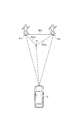


Classifications
-
- B—PERFORMING OPERATIONS; TRANSPORTING
- B60—VEHICLES IN GENERAL
- B60R—VEHICLES, VEHICLE FITTINGS, OR VEHICLE PARTS, NOT OTHERWISE PROVIDED FOR
- B60R11/00—Arrangements for holding or mounting articles, not otherwise provided for
- B60R11/04—Mounting of cameras operative during drive; Arrangement of controls thereof relative to the vehicle
-
- G—PHYSICS
- G06—COMPUTING OR CALCULATING; COUNTING
- G06V—IMAGE OR VIDEO RECOGNITION OR UNDERSTANDING
- G06V20/00—Scenes; Scene-specific elements
- G06V20/50—Context or environment of the image
- G06V20/56—Context or environment of the image exterior to a vehicle by using sensors mounted on the vehicle
- G06V20/58—Recognition of moving objects or obstacles, e.g. vehicles or pedestrians; Recognition of traffic objects, e.g. traffic signs, traffic lights or roads
-
- G—PHYSICS
- G08—SIGNALLING
- G08G—TRAFFIC CONTROL SYSTEMS
- G08G1/00—Traffic control systems for road vehicles
- G08G1/16—Anti-collision systems
-
- G—PHYSICS
- G08—SIGNALLING
- G08G—TRAFFIC CONTROL SYSTEMS
- G08G1/00—Traffic control systems for road vehicles
- G08G1/16—Anti-collision systems
- G08G1/165—Anti-collision systems for passive traffic, e.g. including static obstacles, trees
-
- G—PHYSICS
- G08—SIGNALLING
- G08G—TRAFFIC CONTROL SYSTEMS
- G08G1/00—Traffic control systems for road vehicles
- G08G1/16—Anti-collision systems
- G08G1/166—Anti-collision systems for active traffic, e.g. moving vehicles, pedestrians, bikes
-
- B—PERFORMING OPERATIONS; TRANSPORTING
- B60—VEHICLES IN GENERAL
- B60R—VEHICLES, VEHICLE FITTINGS, OR VEHICLE PARTS, NOT OTHERWISE PROVIDED FOR
- B60R2300/00—Details of viewing arrangements using cameras and displays, specially adapted for use in a vehicle
- B60R2300/10—Details of viewing arrangements using cameras and displays, specially adapted for use in a vehicle characterised by the type of camera system used
Definitions
- the present invention relates to an object detection device that detects a target object from the host vehicle or the like and a driving support device that performs collision avoidance support between the host vehicle and the target object based on a detection result of the object detection device.
- the target object It is necessary to detect the target object with high accuracy from the traveling host vehicle in order to use it for collision determination between the host vehicle and the target object (for example, a pedestrian or another vehicle).
- the target object for example, a pedestrian or another vehicle.
- movement information for example, movement speed, movement vector, movement amount
- a radar sensor for example, movement speed, movement vector, movement amount
- the lateral movement speed of an object existing ahead of the traveling path of the host vehicle is acquired, and the object can enter the traveling path of the host vehicle by comparing the lateral movement speed with a threshold value. Judging whether there is sex.
- an object on the traveling path of the own vehicle is detected by a radar, and the speed obtained by subtracting the moving speed of the own vehicle from the apparent moving speed of the object detected by the radar is set as the moving speed of the object.
- the moving speed is compared with a threshold value to determine whether or not the object is a moving object.
- an object moves by comparing a reference trajectory of the stationary object and a trajectory of the object detected from the image with reference to a stationary object in which the feature amount in the image is remarkable. Whether it is an object or not is discriminated.
- a stationary object is erroneously determined as a moving object.
- a moving object may be erroneously determined as a stationary object. For example, when an object exists 30 meters ahead, a lateral movement amount of 20 cm corresponds to that the vehicle is deflected by about 0.4 deg.
- a fine deflection is performed in a yaw rate sensor mass-produced as a vehicle. Since it is difficult to detect this, it is difficult to correctly cancel out the minute deflection.
- an object having a remarkable feature amount in an image is detected as a stationary object.
- an object a vehicle or the like
- the object moving at a very low speed becomes a reference, so that the determination accuracy as to whether it is a moving object is lowered.
- an object of the present invention is to provide an object detection device and a driving support device that can obtain highly accurate movement information of a target object.
- An object detection device is an object detection device that detects a target object from a predetermined mounting position, detects an object from the predetermined mounting position, and acquires the position of the target object when the target object is detected.
- Fixed object detection that detects the position of a fixed object existing around the position of the target object detected by the object detection unit from a predetermined mounting position when the target object is detected by the object detection unit and the object detection unit ,
- a reference point setting unit that sets the position of the fixed object detected by the fixed object detection unit as a reference point, and a reference point set by the reference point setting unit when the target object is detected by the object detection unit
- a movement information calculation unit that calculates movement information of the target object from the position of the target object acquired by the object detection unit.
- the object detection unit detects an object from a predetermined mounting position, and if the target object can be detected, the position of the target object (relative position with respect to the predetermined mounting position) is acquired.
- the predetermined mounting position include a vehicle, a moving body other than the vehicle, a structure, and a road.
- the object detection device detects the position of the fixed object existing around the position of the target object by the fixed object detection unit. Since this fixed object is fixed, it does not move from its fixed position.
- the reference point setting unit sets the position of the fixed object as a reference point. This reference point is always a stationary point (a point that does not move).
- the movement information calculation unit calculates movement information (for example, movement vector, movement amount, movement speed) of the target object from the position of the target object with reference to the reference point.
- the movement information of the target object is not information based on a predetermined mounting position but information based on a stationary point at all times. Therefore, the movement information is not affected by the movement of a predetermined mounting position of the vehicle or the like, and is not affected by the deflection even if the predetermined mounting position is deflected.
- the object detection apparatus can obtain the movement information of the target object with high accuracy by setting the position of the fixed object as the reference point and calculating the movement information of the target object. By using this highly accurate movement information, it is possible to determine with high accuracy whether the object is a moving object or a stationary object.
- the movement information calculation unit is acquired at different timings depending on the object detection unit with reference to the reference point set by the reference point setting unit when the target object is detected by the object detection unit. It is preferable to calculate the movement information of the target object from the change in the position of the target object. As described above, the movement information of the target object can be calculated from the change in each position of the target object acquired at different timings using the reference point (the position of the fixed object) as a reference, and the movement information is a predetermined mounting position. Unaffected by movement of
- the fixed object detection unit acquires the feature amount of the fixed object existing on the road or the roadside around the position of the target object detected by the object detection unit from a predetermined mounting position. It is preferable to have a feature amount acquisition unit, and the reference point setting unit sets the reference point based on the feature amount acquired by the feature amount acquisition unit.
- the feature amount acquisition unit acquires a characteristic feature amount possessed by the fixed object existing on the road or roadside around the position of the target object. Then, the reference point setting unit sets a reference point based on the feature amount. As described above, in the object detection device, by acquiring the feature amount of the fixed object, the fixed object existing on the road or on the road side can be detected easily and with high accuracy, and the reference point can be set.
- the feature amount acquisition unit acquires the feature amount on the road surface around the position of the target object acquired by the object detection unit, and the reference point setting unit is acquired by the feature amount acquisition unit.
- the reference point may be set on the road surface based on the feature amount on the road surface.
- the feature amount acquisition unit acquires a feature amount on the road surface around the position of the target object as an example of the feature amount of the fixed object existing on the road or on the road side.
- This feature amount for example, there is a luminance gradient on the road surface.
- the reference point setting unit sets a reference point on the road surface based on the feature amount. Since this reference point is a point on the road surface of the road, it is always a stationary point. Thus, this object detection device can set a point that is always stationary on the road as a reference point by setting a point on the road surface as a reference point based on the feature quantity on the road surface.
- the feature amount acquisition unit acquires a pattern that matches the pattern information of the fixed object installed on the road or on the roadside around the position of the target object detected by the object detection unit.
- the reference point setting unit may be configured to set the position of the fixed object having the pattern acquired by the feature amount acquisition unit as the reference point.
- the feature amount acquisition unit performs pattern matching using pattern information of a fixed object installed on the road or roadside around the position of the target object, and acquires a pattern that matches the pattern information.
- the fixed object installed on the road or on the road side is a fixed object having pattern information that can be recognized on the road or on the road side, and examples thereof include traffic signs and traffic lights.
- the pattern information of the fixed object includes, for example, pattern information such as numbers, symbols, characters, and patterns drawn in the traffic sign, and pattern information of the outer shape of the traffic sign.
- the reference point setting unit sets the position of the fixed object having the acquired pattern as a reference point. Since this reference point is the position of a fixed object installed on the road or on the road side, it is always a stationary point.
- this object detection device sets the position of the fixed object installed on the road or the road side as a reference point based on the pattern information of the fixed object installed on the road or the road side.
- a point that is always stationary on the road or on the roadside can be set as the reference point.
- the feature amount acquisition unit is a dimension threshold range set from dimension information of a fixed object installed on the road or on the road side around the position of the target object detected by the object detection unit.
- the dimensions of the fixed object that falls within the reference point may be acquired, and the reference point setting unit may set the position of the fixed object having the dimension acquired by the feature amount acquisition unit as the reference point.
- the feature amount acquisition unit performs dimension determination based on the dimension threshold range set from the dimension information of the fixed object installed on the road or roadside around the position of the target object, and objects that fall within the dimension threshold range Get the dimensions of.
- the fixed object installed on the road or on the road side is a fixed object having dimensional information that is clearly different from that of the target object such as a pedestrian or a vehicle.
- the reference point setting unit sets the position of the fixed object having the acquired dimension as a reference point. Since this reference point is the position of a fixed object installed on the road or on the road side, it is always a stationary point.
- this object detection device sets the position of a fixed object installed on the road or road side as a reference point based on the dimension information of the fixed object installed on the road or road side.
- a point that is always stationary on the road or on the roadside can be set as the reference point.
- the movement information calculation unit is set by the reference point setting unit and the relative information between the reference point set by the reference point setting unit and the position of the target object previously acquired by the object detection unit.
- the movement information of the target object is calculated based on the obtained reference point and relative information between the position of the target object acquired this time by the object detection unit.
- the movement information calculation unit calculates relative information between the reference point and the previous position of the target object (for example, a relative vector or a relative position with respect to the reference point) and calculates relative information between the reference point and the current position of the target object. .
- the relative information is not relative information based on the predetermined mounting position but is relative information based on the position of the fixed object, and thus does not include the amount of movement of the predetermined mounting position.
- the movement information calculation unit calculates movement information from the previous position to the current position of the target object based on the two pieces of relative information. In this way, the movement information of the target object can be calculated from each position of the target object with reference to the reference point, and the movement information is not affected by the movement of the predetermined mounting position.
- the reference point setting unit has acquired a movement amount not less than 0 times and not more than 1 time the amount of movement of the target object detected in the object detection unit in the lateral direction by the object detection unit. It is preferable to set the reference point from the periphery of the lateral position added from the lateral position of the target object to the lateral movement direction.
- the reference point setting unit uses the predicted lateral movement amount, and moves the movement amount not less than 0 times and not more than 1 times the lateral movement amount from the lateral position of the target object in the lateral movement direction.
- Next reference point is set from the side position added to the side. Since the reference point to be set is added with a lateral movement amount of 0 times or more and 1 time or less to the current lateral position of the target object, the lateral position includes the current lateral position of the target object and the next predicted lateral position. Will be located between.
- the reference point setting unit has acquired a movement amount that is not less than 1 and not more than 2 times the movement amount in the distance direction of the target object detected by the object detection unit. It is preferable to set the reference point from the periphery of the distance direction position added from the distance direction position of the target object to the predetermined mounting position side in the distance direction.
- the reference point setting unit uses the predicted movement amount in the distance direction, and a predetermined amount of movement amount that is 1 to 2 times the movement amount in the distance direction from the position in the distance direction of the target object.
- the next reference point is set around the distance position added to the position side (front side). Since the set reference point is added with a distance movement amount of 1 to 2 times the current distance position of the target object, the distance position is a predetermined mounting position from the next predicted distance position of the target object. Will be located on the side.
- the processing area for setting the reference point can be narrowed down, and the processing load and memory capacity can be reduced. Furthermore, even if the target object has moved to the predetermined mounting position side, the reference point is located on the predetermined mounting position side (near side) from the next predicted distance position of the target object. There is nothing hidden behind objects.
- the object detection apparatus of the present invention includes a movement information acquisition unit that acquires movement information of a predetermined mounting position, and the reference point setting unit is configured to determine the set reference point based on the movement information acquired by the movement information acquisition unit. It is preferable to set a new reference point around the moved position.
- the position of the target object (apparent position) acquired by the object detection unit is a position obtained by adding the movement amount of the predetermined mounting position to the movement amount of the target object.
- the movement information of the moving object calculated by the movement information calculation unit does not include the movement information of the predetermined mounting position. Therefore, the set reference point does not take into account the movement of the predetermined mounting position. Therefore, when calculating the relative information between the position of the target object newly acquired by the object detection unit and the reference point, the reference point needs to be moved in consideration of the movement information of the predetermined mounting position.
- the reference point setting unit sets a new reference point around the position where the set reference point is moved based on the movement information of the predetermined mounting position. Since a new reference point is set around the position moved from the reference point set in this way with the movement information of the predetermined mounting position, the processing area for setting the reference point can be narrowed down, and the processing load and memory The amount can be reduced.
- the object detection apparatus of the present invention includes a determination unit that determines whether the target object detected by the object detection unit is a moving object or a stationary object based on the movement information calculated by the movement information calculation unit. In the object detection apparatus, it is possible to determine with high accuracy whether the target object is a moving object or a stationary object by using the movement information calculated with high accuracy when determining.
- a driving support apparatus is a driving support apparatus that performs collision avoidance support between the host vehicle and a target object, and includes any of the object detection apparatuses described above, and is based on a detection result of the object detection apparatus. It is characterized by performing collision avoidance support.
- the above object detection apparatus can obtain highly accurate movement information of the target object, and can use the highly accurate movement information to determine whether the target object is a moving object or a stationary object with high accuracy. Therefore, in the driving support device, the collision between the host vehicle and the target object is performed by using the detection result of the object detection device (high-precision target object movement information, high-precision moving object / stationary object discrimination result, etc.). Avoidance support can be performed with high accuracy.
- highly accurate movement information of the target object can be obtained by calculating the movement information of the target object by setting the position of the fixed object as a reference point.
- the object detection device and the driving support device according to the present invention are applied to a collision prediction device mounted on a vehicle.
- the collision prediction apparatus detects a target object from a stereo camera, performs a collision determination between the target object and the host vehicle, and if there is a possibility of a collision, for collision avoidance and collision damage reduction.
- Provide support In particular, the collision prediction apparatus according to the present embodiment calculates the movement amount of the target object, determines whether the target object is a moving object or a stationary object based on the movement amount of the target object, and determines whether the target object is a moving object / a stationary object. Accordingly, a threshold value for collision determination is set.
- the target object includes a moving object and a stationary object. Examples of moving objects include pedestrians, bicycles, and vehicles. Examples of stationary objects include utility poles and traffic signs.
- FIG. 1 is a configuration diagram of a collision prediction apparatus according to the present embodiment.
- FIG. 2 is an explanatory diagram of a movement vector calculation method using a reference point on the road surface.
- FIG. 3 is an explanatory diagram of a reference point setting method using the lateral movement amount.
- FIG. 4 is an explanatory diagram of a reference point setting method using the distance movement amount.
- FIG. 5 is an explanatory diagram of a reference point setting process using a movement amount performed by the system ECU.
- FIG. 6 is an explanatory diagram of a reference point movement process performed by the system ECU.
- FIG. 7 is an explanatory diagram of a collision determination process performed by the system ECU.
- the collision prediction apparatus 1 sets a feature point having a large feature amount on the road surface around the position of the target object as a reference point in order to calculate the movement amount (movement vector) of the target object with high accuracy.
- a movement vector (the movement vector is composed of a movement amount and a movement direction) is calculated using the previous and current relative vectors of the target object.
- the collision prediction apparatus 1 sets a reference point using the amount of movement of the target object, and calculates the relative vector from the set reference point and the previous position of the target object.
- the collision prediction apparatus 1 moves the reference point from the previously set reference point according to the movement information of the host vehicle, and the new reference point thus moved and the current position of the target object.
- the relative vector is calculated from
- the position P t1 in FIG. 2 is the position of the target object (pedestrian) detected at the previous time t1
- the position P t2 is the position of the target object detected at the current time (current time) t2.
- a reference point S is set on the road surface around the positions P t1 and P t2 of the target object.
- the periphery of the positions P t1 and P t2 for setting the reference point is between the horizontal position of the position P t1 (horizontal position) and the horizontal position of the position P t2 in the horizontal direction, and in the distance direction (depth direction).
- a point having a large feature amount is selected from the feature points on the road surface extracted from the captured image of the stereo camera.
- the luminance gradient (by the edge processing for each pixel of the target object peripheral image ( A point having a large feature amount) is selected, and is a boundary of a white line or a road joint drawn on the road surface.
- a movement vector MV is obtained.
- the relative position from the reference point S may be used instead of the relative vector.
- the magnitude of the movement vector MV is the amount of movement of the target object in a certain time, and the direction is the direction of movement of the target object in a certain time.
- a time-series movement vector MV calculated at regular intervals is a trajectory of the target object.
- the reference point is a stationary point that is always stationary. Since the relative vector of the target object with respect to the reference point (point on the road surface) is obtained, the relative vector does not include movement information of the host vehicle. Therefore, the movement vector (movement amount) obtained from the relative vector is not affected by the movement of the own vehicle, and is not affected by the deflection even if the own vehicle is deflected.
- FIG. 3 shows a case where the target object has moved sideways as viewed from the host vehicle for easy understanding.
- the position P t1 in FIG. 3 is the position of the target object detected at the previous time t1
- the position P t2 is the position of the target object detected at the current time t2. It is assumed that the target object moves next time according to the same movement vector MV ′ as the movement vector MV between the previous position P t1 and the current position P t2 .
- the position P t3 ′ is the next predicted position.
- the amount of horizontal difference between the previous position P t1 and the current position P t2 (the size of the movement vector MV in the horizontal direction) is the horizontal movement amount MW.
- the lateral position of the reference point is the position between the lateral position of the position P t2 and the next lateral position. Get in between.
- FIG. 4 shows a case where the target object moves to the near side (the own vehicle side) for easy understanding.
- the position P t1 in FIG. 4 is the position of the target object detected at the previous time t1
- the position P t2 is the position of the target object detected at the current time t2. It is assumed that the target object moves next time according to the same movement vector MV ′ as the movement vector MV between the previous position P t1 and the current position P t2 .
- the position P t3 ′ is the next predicted position.
- the difference amount (the size in the distance direction of the movement vector MV) in the distance direction (depth direction) between the previous position P t1 and the current position P t2 is the distance movement amount MD.
- the distance position of the reference point is surely placed at the position P t2 and the front side of the next position. Will be located.
- the next reference point is set by combining the setting of the reference point using the lateral movement amount and the setting of the reference point using the distance movement amount.
- a relative vector of a position P t2 (becoming the previous position in the next processing) viewed from the set reference point is calculated. This relative vector is used as the relative vector of the previous position in the next processing, and is used in the calculation of the movement vector.
- the same feature point on the road surface moves in accordance with the movement of the host vehicle in the coordinate system handled in the process of the host vehicle while one step time elapses. Accordingly, when the reference point is set on the coordinate system handled in the process of the host vehicle in the previous process as described above, the feature point on the road surface that is the set reference point is after one step time has elapsed. In the next processing, the vehicle moves on the coordinate system handled in the processing in the host vehicle. However, when the host vehicle is stopped, the same position is obtained on the coordinate system handled in the process of the host vehicle.
- the reference point set in the previous process is set in the own vehicle according to the movement information of the own vehicle (the movement amount calculated by the own vehicle speed, the yaw rate, etc.) during the elapse of one step time.
- the movement information of the own vehicle the movement amount calculated by the own vehicle speed, the yaw rate, etc.
- pattern matching is performed by using the image feature pattern of the feature point on the road surface that is the reference point (for example, the luminance value or feature amount of each pixel with the feature point as the center) around the moved point.
- the image pattern to be searched is searched, and the matched point is determined as a reference point.
- a relative vector of the position of the target object viewed from the determined reference point is calculated.
- the movement vector (movement amount) of the target object in this one step time is calculated.
- the collision prediction device 1 includes a stereo camera 10, a steering angle sensor 11, a yaw rate sensor 12, a wheel speed sensor 13, an alarm device 20, a collision avoidance support device 21, a seat belt control device 22, a seat control device 23, a brake control device 24, and A system ECU [Electronic Control Unit] 30 is provided.
- the stereo camera 10 corresponds to the object detection unit described in the claims
- the yaw rate sensor 12 and the wheel speed sensor 13 correspond to the movement information acquisition unit described in the claims
- the system ECU 30 Each process corresponds to a fixed object detection unit, a feature amount acquisition unit, a reference point setting unit, a movement information calculation unit, and a determination unit described in the claims.
- the stereo camera 10 is composed of a pair of left and right cameras for photographing the front of the host vehicle and an image processing device. Each of the pair of left and right cameras of the stereo camera 10 captures images at regular time intervals (for example, every 1/30 seconds), and acquires a left image and a right image. Then, the image processing apparatus of the stereo camera 10 performs object detection processing using the left and right images (stereo images), and when the object (target) can be detected, information on the object (for example, the stereo camera 10 (self (Relative distance and direction (position information) from the vehicle) to the object, and the shape and size of the object).
- the object detection process using this stereo image applies a conventional well-known technique, for example, performs a correlation operation between stereo images, calculates the distance to the object using the parallax obtained from the calculation result, Detect an object.
- the stereo camera 10 transmits information on the presence / absence of the object and information on each object (for each target) to the system ECU 30 as a stereo camera signal at regular intervals.
- the object to be detected by the stereo camera 10 has a certain size and height such as a pedestrian, a bicycle, a vehicle, a power pole, and a traffic sign as described above.
- processing is performed in a pixel unit coordinate system in the horizontal direction / vertical direction of an image captured by the camera, and object information is data in pixel units.
- an identification number is assigned to the detected target, and when the same target is detected at different times, the same identification number is assigned and the number of detections is counted. Information of these identification numbers and the number of detection times is also transmitted as stereo camera signals as information for each target.
- the steering angle sensor 11 is a sensor that detects the steering angle input to the steering wheel by the driver.
- the steering angle sensor 11 detects the steering angle at regular intervals, and transmits the detected steering angle to the system ECU 30 as a steering angle signal.
- the yaw rate sensor 12 is a sensor that detects the yaw rate acting on the host vehicle.
- the yaw rate sensor 12 detects the yaw rate at regular intervals, and transmits the detected yaw rate to the system ECU 30 as a yaw rate signal.
- the wheel speed sensor 13 is a sensor that is provided on each of the four wheels of the vehicle and detects the rotational speed of the wheel (number of pulses corresponding to the rotation of the wheel).
- the wheel speed sensor 13 detects the number of wheel rotation pulses at regular time intervals, and transmits the detected wheel rotation pulse number to the system ECU 30 as a wheel speed signal.
- the system ECU 30 calculates the wheel speed from the number of rotation pulses of each wheel, and calculates the vehicle body speed (vehicle speed) from the wheel speed of each wheel.
- the warning device 20 is a device for warning the driver of the host vehicle.
- Alarms include buzzer (alarm sound) output, alarm message audio output and display, and the like.
- the alarm device 20 receives an alarm control signal from the system ECU 30, the alarm device 20 outputs an alarm based on the alarm control signal.
- the collision avoidance assistance device 21 is a device for avoiding collision and reducing impact caused by collision by steering control (automatic steering, steering assist, etc.).
- the collision avoidance assistance device 21 receives a collision avoidance control signal from the system ECU 30, it performs steering control based on the collision avoidance control signal.
- the seat belt control device 22 is a device for reducing the collision damage by controlling the tightening force of the seat belt.
- the seat belt control device 22 receives the seat belt control signal from the system ECU 30, the seat belt control device 22 controls the tightening force of the seat belt based on the seat belt control signal.
- the sheet control device 23 is a device for reducing the collision damage by controlling the position and posture of the sheet.
- the seat control device 23 controls the position and posture of the seat based on the seat control signal.
- the brake control device 24 is a device for mitigating collision avoidance and impact caused by collision by brake control (automatic stop, automatic deceleration, brake assist, etc.).
- brake control automatic stop, automatic deceleration, brake assist, etc.
- the brake control device 24 performs brake control based on the brake control signal.
- the system ECU 30 is an electronic control unit that includes a CPU [Central Processing Unit], ROM [Read Only Memory], RAM [Random Access Memory], and the like, and performs overall control of the collision prediction apparatus 1.
- the system ECU 30 receives a stereo camera signal from the stereo camera 10 at regular intervals. Further, the system ECU 30 receives detection signals from the sensors 11, 12, and 13. Then, the system ECU 30 uses these stereo camera signals and the respective detection signals to perform the following processes (reference point setting process, previous relative vector calculation process, reference point movement process, current relative vector calculation process, movement vector calculation process).
- a control signal is transmitted to a device necessary for mitigation.
- the reference point setting process in the system ECU 30 corresponds to the fixed object detecting unit and the feature amount acquiring unit described in the claims, and the reference point setting process and the reference point moving process are included in the reference point setting unit described in the claims.
- the previous relative vector calculation process, the current relative vector calculation process, and the movement vector calculation process correspond to the movement information calculation unit described in the claims, and the moving object determination process corresponds to the determination unit described in the claims. .
- the system ECU 30 obtains the movement trajectory of the target and determines the collision between the target and the host vehicle. Further, the system ECU 30 performs processing for each target when the stereo camera 10 detects the target. Further, the system ECU 30 performs processing in a coordinate system of length units in the horizontal direction / distance direction (for example, several tens of centimeters, several centimeters), and the horizontal / vertical direction of the image obtained from the stereo camera 10 Data in pixel units is converted into data in length units in the horizontal direction / distance direction. Processing may be performed in a coordinate system in units of pixels in the horizontal / vertical direction of the image without performing such conversion.
- FIG. 5 is a diagram when viewed from a coordinate system fixed on the ground.
- the system ECU 30 uses the previous position P t1 and the current position P t2 of the target to calculate the lateral movement amount MW based on the lateral position difference, and calculates the distance movement amount MD based on the distance position difference. Then, the system ECU 30 adds MW / 2, which is 1 ⁇ 2 times the lateral movement amount MW, from the current position Pt2 to the lateral movement direction side, and adds 2 ⁇ MD, which is twice the distance movement amount MD, to the near side.
- the movement predicted position PP added to is calculated.
- the system ECU 30 sets a candidate area PA around the predicted movement position PP.
- the size of the candidate area PA is set in consideration of the coordinate system length unit, the processing capacity of the system ECU 30, the memory capacity, and the like. Further, the system ECU 30 multiplies the feature amount and the weighting coefficient for each corresponding coordinate point by using the feature amount data of each coordinate point in the candidate area PA and the weighting coefficient data of each coordinate point, and obtains the multiplication value. obtain. Then, the system ECU 30, setting a coordinate point having the largest multiplied value in the multiplication value of each coordinate point in the candidate area PA as the next reference point S p.
- the candidate area PA is an area of 11 units in the horizontal direction / distance direction in the coordinate system unit, and the coordinate point of the movement predicted position PP is 0 in the horizontal / distance direction index. And is in the range of -5 to 5 with 0 as the center.
- an image feature amount an absolute value of a luminance gradient by edge processing is used, and an example of feature amount data PD of each coordinate point in the candidate area PA is shown.
- this feature amount data PD the feature amount is indicated by an integer value of 0 to 12, and there is a white line (lane) at the positions of the horizontal indexes ⁇ 3 and ⁇ 2, and the feature amount is large.
- weighting coefficient map CM in the candidate area PA is shown.
- the weighting coefficient is indicated by an integer value of 0 to 12
- the coordinate point of the movement predicted position PP of the index 0 in the horizontal direction and the index 0 in the distance direction is 12 of the maximum weighting coefficient, The farther from the coordinate point, the smaller the weighting factor.
- the calculation result CR by this feature-value data PD and the weighting coefficient map CM is shown.
- the previous relative vector calculation process will be described. Setting the reference point S p at the reference point setting process, the system ECU 30, calculates the reference point S p and the current position P t2 using the relative vector of the reference point S p of the current relative to the position P t2 To do. This relative vector is used as the relative vector of the previous position in the next movement vector calculation process.
- FIG. 6 shows the relative vector RV t2 of the previous position P t2 relative to the reference point S p that was last set.
- FIG. 6 is a diagram when viewed from a coordinate system fixed to the host vehicle.
- 1 step time is before the previous setting the reference point S p is the reference point setting process
- the system ECU 30 the own Using the vehicle speed and the yaw rate, movement information (for example, movement vector, movement amount) of the host vehicle for one step time is calculated.
- movement information for example, movement vector, movement amount
- the system ECU 30 sets the search area SA around the predicted movement position PP.
- the size of the search area SA is set in consideration of the coordinate system length unit, the processing capacity of the system ECU 30, the memory capacity, and the like.
- the system ECU 30, the image feature pattern of the reference point S p in the search area SA (e.g., pixel information, feature amount) performs matching processing with the coordinate points that match the image feature pattern of the reference point S p time and of the reference point S M.
- each coordinate point in the search area SA correlates with the image feature pattern of the reference point S p, the highest coordinate points correlated with the current reference point S M.
- the current position P t3 target objects in the case of moving only the movement amount of the target ' Is shown.
- the current position P t3 is a position that takes into account the movement of the host vehicle for one step time from the position P t3 ′ only by the movement of the target.
- one step time reference point moves the moving amount of the vehicle in partial S It is necessary to use M.
- the movement vector calculation process will be described.
- the system ECU 30 calculates the relative vector RV t2 of the previous position P t2 calculated in the previous relative vector calculation process one step time ago. using the relative vector RV t3 of the current position P t3, calculates a movement vector to the current position P t3 from the position P t2 last (see FIG. 2).
- the movement vector is calculated from the change in the previous position P t2 and the current position P t3 detected at different timings with the reference point S as a reference.
- the magnitude of this movement vector is the movement amount in one step time, and the direction of the movement vector is the movement direction in one step time.
- the moving object discrimination process will be described.
- the system ECU 30 determines whether or not the movement amount of the target is greater than or equal to the moving object determination threshold.
- the moving object determination threshold is a threshold for determining whether or not the object is a moving object from the amount of movement, and is set in advance by adaptation through experiments, simulations, or the like.
- the system ECU 30 determines that the target is a moving object if the amount of movement of the target is equal to or greater than the moving object determination threshold, and determines that the target is a stationary object if it is less than the moving object determination threshold.
- This set threshold value is a collision determination threshold value, and includes a collision determination threshold value SS for normal use (particularly for a stationary object) and a collision determination threshold value MS for a moving object.
- Each of the collision determination thresholds is a threshold for determining whether or not the own vehicle may collide with an object based on the integrated value of the collision probability for each predicted collision position, and is set in advance by adaptation through experiments, simulations, or the like. Is done.
- the collision determination threshold MS for the moving object is set to be lower than the normal collision determination threshold SS.
- a value that is likely to be determined as a possibility of collision is set.
- a stationary object such as a utility pole
- Value is set.
- the system ECU 30 sets a normal collision determination threshold SS as a default threshold. Further, in the system ECU 30, when the target is determined as a moving object in the moving object determination process, a collision determination threshold value MS for the moving object is set, and the target is determined as a stationary object in the moving object determination process. If so, a normal collision determination threshold SS is set.
- Each surface of the vehicle (front surface, rear surface, right side surface, left side surface) is divided into a plurality of sections at predetermined intervals. This partitioning is preset by matching. In the example of FIG. 7, the division of only the front surface of the host vehicle V is shown, and the vehicle is divided into five sections CP1, CP2, CP3, CP4, and CP5.
- the system ECU 30 estimates the movement trajectory of the target from the time series data of the target movement vector calculated by the movement vector calculation process, and also calculates the own vehicle speed, yaw rate, and steering angle from the time series data of the own vehicle. Estimate the movement trajectory.
- the position where the target collides with the own vehicle (the own vehicle's movement trajectory). Predict which section of which plane).
- the movement locus ML of the target approaching the own vehicle V is shown with respect to the own vehicle V that goes straight, and the middle of the front surface of the own vehicle V is shown from this movement locus ML.
- the section CP3 and the section CP2 adjacent to the left are predicted as collision positions.
- the system ECU 30 calculates the collision probability of each section around the collision prediction position. For example, the collision probability is calculated in a normal distribution with the predicted collision position as the center, or a high collision probability is calculated only for the predicted collision position. Further, the system ECU 30 adds the calculated collision probability to the previous integrated value for each section of the predicted collision position, and integrates the collision probability. In the case of the example shown in FIG. 7, the cumulative value PD3 of the collision probability for the middle section CP3 in front of the host vehicle V is the largest, and the cumulative value PD2 of the collision probability for the section CP2 adjacent to the left is the second largest.
- the collision determination process will be described.
- the system ECU 30 determines whether or not the collision probability integrated value is greater than or equal to the set collision determination threshold for each collision position section on each surface of the host vehicle (only the section in which the integrated value is updated in the collision probability integration process). Determine whether. Then, the system ECU 30 determines that there is a possibility of collision (high possibility) when the integrated value of the collision probability is equal to or greater than the collision determination threshold value, and when the integrated value of the collision probability is less than the collision determination threshold value. It is determined that there is no possibility of collision (low possibility). In the case of the example in FIG.
- the integrated value PD3 of the collision probability of the section CP3 is equal to or greater than the collision determination threshold value MS. , It is determined that there is a possibility of collision.
- the system ECU 30 determines which one (one or more) of alarm, steering, seat belt, seat, and brake to operate based on the integrated value of the TTC, the predicted collision position, and the collision probability for the target. to decide.
- the system ECU 30 sets a control amount or an output command or the like based on the integrated value of the TTC, the predicted collision position, and the collision probability for each device to be operated, and the alarm device 20, the collision avoidance support device 21, the seat belt control.
- a control signal is transmitted to the corresponding device among the device 22, the seat control device 23, and the brake control device 24.
- FIG. 8 is a flowchart showing a flow of operations in the collision prediction apparatus according to the present embodiment.
- the collision prediction apparatus 1 repeatedly performs the following operation at regular intervals.
- the stereo camera 10 picks up images with a pair of left and right cameras, performs object detection processing using the left and right images (stereo images), and if the target object (target) can be detected, the position of the target object Information etc. are acquired (S1).
- the stereo camera 10 transmits to the system ECU 30 a stereo camera signal including the presence / absence information of the target object and the position information of each target when the target object exists.
- the system ECU 30 receives this stereo camera signal, acquires position information and the like for each target when the target exists, and holds the position information and the like. If the target does not exist, the current process ends.
- the steering angle sensor 11 detects the steering angle and transmits a steering angle signal to the system ECU 30.
- the system ECU 30 receives this steering angle signal and acquires the steering angle.
- the yaw rate sensor 12 detects the yaw rate and transmits a yaw rate signal to the system ECU 30.
- the system ECU 30 receives this yaw rate signal and acquires the yaw rate.
- the wheel speed sensor 13 of each wheel detects the number of rotation pulses of the wheel and transmits a wheel speed signal to the system ECU 30.
- the system ECU 30 receives a wheel speed signal for each wheel, calculates a wheel speed from the number of rotation pulses of each wheel, and calculates a vehicle speed (own vehicle speed) from the wheel speed of each wheel.
- the system ECU 30 determines the number of detections for each target (S2). In the system ECU 30, when it is determined that the number of detection times of the target is the first time, the collision determination threshold value is set to the normal collision determination threshold value (S3).
- the processes of S4 to S7 are performed after S3. However, when the number of times of detection is the first, the process is terminated without performing the processes of S4 to S7. Since a movement trajectory or the like cannot be obtained with only one detection information of the target, collision determination or the like cannot be performed.
- the system ECU 30 sets the collision determination threshold value to the normal collision determination threshold value when it is determined that the number of detection times of the target is the second time (S8). Then, the system ECU 30 calculates the lateral movement amount from the lateral difference between the detection position of the previous (first time) target object and the detection position of the current (second time) target object, and the lateral movement amount from the current detection position.
- the lateral position of the reference point is set from the vicinity of the position obtained by adding the movement amount of 1/2 times the lateral movement direction side (S9). Further, the system ECU 30 calculates the distance movement amount from the difference in the distance direction between the previous detection position and the current detection position, and adds the movement amount twice the distance movement amount from the current detection position to the front side.
- the system ECU 30 calculates a relative vector (which may be a relative position) from the reference point to the current target object position using the set reference point and the current detection position (S11). This relative vector is used in the next processing.
- the processes of S4 to S7 are performed after S11. However, if the number of times of detection is the second time, the process is terminated without performing the processes of S4 to S7. Since the movement vector (corresponding to the movement trajectory of the object) is calculated after the third detection, the collision determination or the like cannot be performed at the second time.
- the system ECU 30 moves the reference point (reference point based only on the movement of the target) set in the previous processing of S9 and S10 using the own vehicle speed and the yaw rate when it is determined that the number of detections of the target is the third or later.
- the movement position is predicted (S12).
- a search area is set around the predicted movement position, and correlation is performed with the feature pattern of the reference point set in the previous processing of S9 and S10 in the search area, and the position of the reference point (the vehicle's position).
- a reference point taking into account the amount of movement is determined (S13).
- the system ECU 30 calculates a relative vector (may be a relative position) from the reference point to the current position of the target object using the determined reference point and the current detection position (S14).
- the system ECU 30 calculates the movement vector (movement amount and movement direction) of the target object from the relative vector calculated in the previous S11 and the relative vector calculated this time (S15). Then, the system ECU 30 determines whether or not the target object is a moving object based on whether or not the movement amount is equal to or greater than the moving object determination threshold (S16). When it is determined in S16 that the moving amount is equal to or greater than the moving object determination threshold, the system ECU 30 determines that the target object is a moving object, and sets a moving object threshold (a loose threshold) as a collision determination threshold (S17). . On the other hand, if it is determined in S16 that the movement amount is less than the moving object determination threshold, the system ECU 30 determines that the target object is a stationary object, and sets a normal threshold as a collision determination threshold (S18).
- the process proceeds to S4, where the system ECU 30 estimates the movement trajectory of the target object from the time-series movement vector calculated for the target object, and time-series data of the host vehicle speed, yaw rate, and steering angle of the host vehicle.
- the movement trajectory of the own vehicle is estimated from the above, and the position of collision with the own vehicle is predicted from the movement trajectory of the target object and the movement trajectory of the own vehicle (S4).
- the system ECU 30 integrates the collision probabilities of the corresponding sections at the predicted collision position (S5). Note that if the movement locus of the target object and the movement locus of the host vehicle do not intersect, the collision position is not predicted and the process of S5 is not performed.
- the system ECU 30 determines whether or not there is a possibility of collision between the host vehicle and the target object depending on whether or not the integrated value of the collision probability at each collision predicted position is equal to or greater than the collision determination threshold (S6). If it is determined in S6 that there is no possibility of a collision, the system ECU 30 ends the current process. On the other hand, if it is determined in S6 that there is a possibility of a collision, the system ECU 30 warns, steers, seat belt, seat, brake based on the integrated value of the collision margin time (TTC), the predicted collision position, and the collision probability.
- TTC collision margin time
- the control amount of the device determined to be activated is set, and the alarm device 20, the collision avoidance support device 21, the seat belt control device 22, the seat control device 23, the brake control are determined.
- a control signal is transmitted to the corresponding device in the device 24 (S7).
- the alarm device 20 receives an alarm control signal from the system ECU 30, the alarm device 20 outputs an alarm based on the alarm control signal.
- the collision avoidance assistance device 21 receives a collision avoidance control signal from the system ECU 30, it performs steering control based on the collision avoidance control signal.
- the seat belt control device 22 receives a seat belt control signal from the system ECU 30, the seat belt control device 22 controls the tightening force of the seat belt based on the seat belt control signal.
- the seat control device 23 controls the position and orientation of the seat based on the seat control signal.
- the brake control device 24 receives a brake control signal from the system ECU 30, the brake control device 24 performs brake control based on the brake control signal.
- this collision prediction apparatus 1 by calculating feature information (movement vector (movement amount, movement direction)) of a target object by setting a feature point on the road surface (a point that does not always move) as a reference point, A highly accurate movement amount of the object can be obtained. As a result, even when the host vehicle makes a fine deflection that cannot be detected by the sensor (especially when the target object is located far away), it is possible to reduce the amount of movement of the target object without being affected by the deflection. Obtainable. Furthermore, it is possible to determine with high accuracy whether the target object is a moving object or a stationary object using this highly accurate movement amount.
- a threshold suitable for a stationary object or a threshold suitable for a moving object can be set as a threshold for collision determination, and collision determination can be performed with high accuracy according to a stationary object or a moving object.
- unnecessary support can be suppressed in the case of a stationary object (the driver does not give a sense of incongruity due to unnecessary support), and safety-oriented support can be performed in the case of a moving object.
- the collision prediction apparatus 1 by setting the next reference point based on the previous movement amount (lateral movement amount, distance movement amount) of the target object, a processing region for setting the reference point is set.
- the aperture can be reduced, and the processing load and the amount of memory can be reduced.
- the reference point is not hidden by the target object even if the target object moves to the own vehicle side.
- the processing region for setting the reference point is determined by determining the reference point by pattern matching around the position where the movement of the host vehicle is moved from the previously set reference point.
- the aperture can be reduced, the processing load and the amount of memory can be reduced, and erroneous matching can be reduced.
- the reference point is a point having a large feature amount on the road surface around the target object as the reference point.
- the reference point may be set by other methods, and the reference point may be set on the road or on the road side.
- An installed fixed object can be used as a reference point.
- FIG. 9 is an explanatory diagram of another reference point setting method, in which (a) shows a case where a traffic sign is set as a reference point, and (b) shows a case where a utility pole is set as a reference point.
- the system ECU 30 holds templates (pattern information) related to various traffic signs installed on the road or on the road side for pattern matching.
- pattern information (features) possessed by a traffic sign include pattern information such as numbers, symbols, characters, and patterns drawn in the sign, and pattern information of the outer shape of the traffic sign.
- Pattern information is set as a template.
- the pattern information of these traffic signs is a pattern that a moving object such as a pedestrian or a vehicle does not have, and can be easily recognized by pattern matching.
- traffic lights in addition to general vehicle traffic lights, pedestrian traffic lights, etc.
- templates relating to traffic lights may be held.
- the template of the characters “stop” and the template of the inverted triangle shape are used. Only one template may be held for one traffic sign, or a plurality of templates may be held.
- the system ECU 30 sets a search area using the previous position P t1 of the target and the current position P t2 (only the current position P t2 may be used).
- the search area is an area around the position of the target (target object) and includes not only the road but also the roadside.
- the size of the search area is set in consideration of the coordinate system length unit, the processing capacity of the system ECU 30, the memory capacity, and the like.
- the system ECU 30 sequentially cuts out a range having the same size as the template from the search area for each template of each fixed object held, and uses the template for the image information (luminance values, etc.) of the cut out range. Matches sequentially.
- the system ECU 30 When the system ECU 30 can search for a pattern that matches the template, the system ECU 30 recognizes a fixed object (such as a traffic sign) on the road or roadside having the pattern, and coordinates the fixed object (coordinate point of the installation location). ) identifies, sets the coordinate point of the fixture as a reference point S p.
- a fixed object such as a traffic sign
- the system ECU 30 recognizes a fixed object (such as a traffic sign) on the road or roadside having the pattern, and coordinates the fixed object (coordinate point of the installation location). ) identifies, sets the coordinate point of the fixture as a reference point S p.
- pattern matching is performed for each of the plurality of templates, and a fixed object such as a traffic sign is recognized from the result of the plurality of pattern matching.
- the system ECU 30 holds a threshold range of dimensional information of various fixed objects installed on the road or roadside for identification with dimensional information.
- the fixed object installed on the road or on the road side is a fixed object having dimensional information that is clearly different from that of a moving object such as a pedestrian or a vehicle.
- As the dimension information (feature amount) of the fixed object for example, there are a width and a height, and a threshold range of these dimension information is set.
- the upper limit threshold of the width is 90 cm
- the lower limit threshold of the height is 4.0 m.
- the stereo camera 10 calculates dimensional information of width and height for each detected object (for each target).
- the system ECU 30 sets a search area in the same manner as described above. Then, the system ECU 30 determines whether each dimension of the target is within the dimension threshold range for the target detected by the stereo camera 10 for each dimension threshold range of each fixed object held. judge.
- determination is performed using each of the plurality of dimension threshold ranges, and it is determined whether or not all the dimension threshold ranges are included.
- the system ECU 30 recognizes the fixed object (electric pole, etc.) and identifies the coordinate point (coordinate point of the installation location) of the fixed object. and, setting a coordinate point of the fixture as a reference point S p.
- the system ECU 30 Setting the installation position of the installed fixture on the road or on the road surface in the reference point setting process as a reference point S p, the system ECU 30, the feature amount the position of the reference point S p (fixture) (pattern information And each dimension information etc.) are stored on a map of a navigation system (not shown). Then, at the next running, the system ECU 30, to set the position of the fixture which is stored on the map of the navigation system (coordinate point) as a reference point S p. Alternatively, at the next travel time, the system ECU 30 sets a search area around the position (coordinate point) of the fixed object stored on the map of the navigation system, and performs the same processes as described above using this search area. Do.
- This search area may be a much narrower area than the search area when a fixed object installed on the road or road surface has not yet been searched.
- the reference point S p is already installed position of the installed fixture on the road or on the road surface is set is stored on the map, it is possible to reduce the processing load and the amount of memory, and more A fixed object (and thus a reference point) installed on the road or on the road surface can be determined at an early timing.
- processing by three methods is shown as the reference point setting processing.
- the system ECU 30 may perform reference point setting processing by one of these three methods, or perform reference point setting processing by combining two or three of these three methods. May be.
- the target object is detected, the possibility of a collision with the target object is determined, and if there is a possibility, the present invention is applied to a device that supports collision avoidance and collision damage reduction. May be applied to other driving assistance devices that perform other assistance using movement information of the target object, or may be applied to an object detection device that only detects a target object (particularly, movement information). You may apply.
- the object detection device is mounted on the vehicle.
- the object detection device may be mounted on a vehicle other than the vehicle, for example, on a moving body other than the vehicle, a structure, or a road.
- a stereo camera is applied as an external sensor for detecting an object.
- a monocular image sensor which can detect the distance, lateral position, and dimension information of an object with a single eye
- a laser radar a feature point of a road surface
- Other external sensors such as a high-density sensor capable of identifying the
- a stereo camera as an external sensor may be fused with a millimeter wave radar, a laser radar, or the like as an operation condition of the device.
- alarm, steering, seat belt, seat, and brake devices are shown as devices to be activated when there is a possibility of a collision.
- one or more of these devices may be used.
- other devices actuators
- the movement amount 1 ⁇ 2 times the horizontal movement amount is moved in the horizontal direction, and the movement amount twice the distance movement amount is moved forward.
- other values such as 1/3 times (magnification between 0 and 1 times) may be used in the horizontal direction, or in the distance direction.
- Other numerical values such as 1.5 times (magnification between 1 and 2 times) may be used.
- the movement vector (movement amount) is calculated and the moving object determination or the collision determination is performed.
- the movement vector may be calculated and the moving object determination or the collision determination may be performed when the number of times detected is detected for the second time.
- a movement vector and a movement amount are obtained as movement information of the target object, and it is determined whether the target object is a movement object based on the movement amount.
- the movement information includes other information such as a movement speed.
- the present invention is applicable to an object detection device that detects a target object from the host vehicle or the like, and a driving support device that performs collision avoidance support between the host vehicle and the target object based on the detection result.
- SYMBOLS 1 ... Collision prediction apparatus, 10 ... Stereo camera, 11 ... Steering angle sensor, 12 ... Yaw rate sensor, 13 ... Wheel speed sensor, 20 ... Alarm device, 21 ... Collision avoidance support device, 22 ... Seat belt control device, 23 ... Seat Control device, 24 ... brake control device, 30 ... system ECU.
Landscapes
- Physics & Mathematics (AREA)
- General Physics & Mathematics (AREA)
- Engineering & Computer Science (AREA)
- Multimedia (AREA)
- Theoretical Computer Science (AREA)
- Mechanical Engineering (AREA)
- Traffic Control Systems (AREA)
- Image Analysis (AREA)
- Length Measuring Devices By Optical Means (AREA)
Abstract
Description
Claims (12)
- 所定の搭載位置から対象物体を検出する物体検出装置であって、
前記所定の搭載位置から物体検出を行い、対象物体を検出した場合に当該対象物体の位置を取得する物体検出部と、
前記物体検出部で対象物体が検出されている場合、前記所定の搭載位置から、前記物体検出部で検出された対象物体の位置周辺に存在する固定物の位置を検出する固定物検出部と、
前記固定物検出部で検出された固定物の位置を基準点として設定する基準点設定部と、
前記物体検出部で対象物体が検出されている場合、前記基準点設定部で設定された基準点を基準として前記物体検出部で取得された対象物体の位置から対象物体の移動情報を算出する移動情報算出部と、
を備えることを特徴とする物体検出装置。 - 前記移動情報算出部は、前記物体検出部で対象物体が検出されている場合、前記基準点設定部で設定された基準点を基準として前記物体検出部によって異なるタイミングで取得された対象物体の位置の変化から対象物体の移動情報を算出することを特徴とする請求項1に記載の物体検出装置。
- 前記固定物検出部は、前記所定の搭載位置から、前記物体検出部で検出された対象物体の位置周辺の道路上又は路側上に存在する固定物の特徴量を取得する特徴量取得部を有し、
前記基準点設定部は、前記特徴量取得部で取得された特徴量に基づいて基準点を設定することを特徴とする請求項1又は請求項2に記載の物体検出装置。 - 前記特徴量取得部は、前記物体検出部で取得された対象物体の位置周辺の路面上の特徴量を取得し、
前記基準点設定部は、前記特徴量取得部で取得された路面上の特徴量に基づいて路面上に基準点を設定することを特徴とする請求項3に記載の物体検出装置。 - 前記特徴量取得部は、前記物体検出部で検出された対象物体の位置周辺において、道路上又は路側上に設置された固定物のパターン情報とマッチングするパターンを取得し、
前記基準点設定部は、前記特徴量取得部で取得されたパターンを持つ固定物の位置を基準点として設定することを特徴とする請求項3又は請求項4に記載の物体検出装置。 - 前記特徴量取得部は、前記物体検出部で検出された対象物体の位置周辺において、道路上又は路側上に設置された固定物の寸法情報から設定された寸法閾値範囲内に入る固定物の寸法を取得し、
前記基準点設定部は、前記特徴量取得部で取得された寸法の固定物の位置を基準点として設定することを特徴とする請求項3~請求項5のいずれか1項に記載の物体検出装置。 - 前記移動情報算出部は、前記基準点設定部で設定された基準点と前記物体検出部で前回取得された対象物体の位置との相対情報と、前記基準点設定部で設定された基準点と前記物体検出部で今回取得された対象物体の位置との相対情報とに基づいて対象物体の移動情報を算出することを特徴とする請求項1~請求項6のいずれか1項に記載の物体検出装置。
- 前記基準点設定部は、前記物体検出部で検出された対象物体の横方向の移動量の0倍以上かつ1倍以下の移動量を、前記物体検出部で取得された対象物体の横方向の位置から横方向の移動方向側に加算した横方向の位置周辺から基準点を設定することを特徴とする請求項1~請求項7のいずれか1項に記載の物体検出装置。
- 前記基準点設定部は、前記物体検出部で検出された対象物体の距離方向の移動量の1倍以上かつ2倍以下の移動量を、前記物体検出部で取得された対象物体の距離方向の位置から距離方向の前記所定の搭載位置側に加算した距離方向の位置周辺から基準点を設定することを特徴とする請求項1~請求項8のいずれか1項に記載の物体検出装置。
- 前記所定の搭載位置の移動情報を取得する移動情報取得部を備え、
前記基準点設定部は、前記設定した基準点を前記移動情報取得部で取得された移動情報に基づいて移動させた位置周辺から新たな基準点を設定することを特徴とする請求項8又は請求項9に記載の物体検出装置。 - 前記移動情報算出部で算出された移動情報に基づいて、前記物体検出部で検出されている対象物体が移動物体かあるいは静止物体かを判別する判別部を備えることを特徴とする請求項1~請求項10のいずれか1項に記載の物体検出装置。
- 自車両と対象物体との衝突回避支援を行う運転支援装置であって、
請求項1~請求項11のいずれか1項に記載の物体検出装置を搭載し、
前記物体検出装置での検出結果に基づいて衝突回避支援を行うことを特徴とする運転支援装置。
Priority Applications (4)
| Application Number | Priority Date | Filing Date | Title |
|---|---|---|---|
| JP2014529239A JP5971341B2 (ja) | 2012-08-09 | 2012-12-14 | 物体検出装置及び運転支援装置 |
| EP12882792.0A EP2884476A4 (en) | 2012-08-09 | 2012-12-14 | OBJECT DETECTION DEVICE AND DRIVING HELP DEVICE |
| CN201280075207.4A CN104584097B (zh) | 2012-08-09 | 2012-12-14 | 物体检测装置和驾驶辅助装置 |
| US14/418,590 US10246030B2 (en) | 2012-08-09 | 2012-12-14 | Object detection apparatus and driving assistance apparatus |
Applications Claiming Priority (2)
| Application Number | Priority Date | Filing Date | Title |
|---|---|---|---|
| JP2012177254 | 2012-08-09 | ||
| JP2012-177254 | 2012-08-09 |
Publications (1)
| Publication Number | Publication Date |
|---|---|
| WO2014024336A1 true WO2014024336A1 (ja) | 2014-02-13 |
Family
ID=50067609
Family Applications (1)
| Application Number | Title | Priority Date | Filing Date |
|---|---|---|---|
| PCT/JP2012/082531 Ceased WO2014024336A1 (ja) | 2012-08-09 | 2012-12-14 | 物体検出装置及び運転支援装置 |
Country Status (5)
| Country | Link |
|---|---|
| US (1) | US10246030B2 (ja) |
| EP (1) | EP2884476A4 (ja) |
| JP (1) | JP5971341B2 (ja) |
| CN (1) | CN104584097B (ja) |
| WO (1) | WO2014024336A1 (ja) |
Cited By (22)
| Publication number | Priority date | Publication date | Assignee | Title |
|---|---|---|---|---|
| JP2015203983A (ja) * | 2014-04-14 | 2015-11-16 | 本田技研工業株式会社 | 衝突可能性判定装置、運転支援装置、衝突可能性判定方法、及び衝突可能性判定プログラム |
| DE102014226187A1 (de) * | 2014-12-17 | 2016-06-23 | Bayerische Motoren Werke Aktiengesellschaft | Kommunikation mittels eines Luftstoßes |
| JP2018088233A (ja) * | 2016-11-24 | 2018-06-07 | 株式会社リコー | 情報処理装置、撮像装置、機器制御システム、移動体、情報処理方法、及びプログラム |
| CN109154820A (zh) * | 2016-05-16 | 2019-01-04 | 本田技研工业株式会社 | 车辆控制系统、车辆控制方法及车辆控制程序 |
| JPWO2018025632A1 (ja) * | 2016-08-05 | 2019-04-18 | 日立オートモティブシステムズ株式会社 | 撮像装置 |
| JP2020507509A (ja) * | 2017-02-10 | 2020-03-12 | ニッサン ノース アメリカ,インク | 自律走行車の動作管理ブロックモニタ |
| US10654476B2 (en) | 2017-02-10 | 2020-05-19 | Nissan North America, Inc. | Autonomous vehicle operational management control |
| US10836405B2 (en) | 2017-10-30 | 2020-11-17 | Nissan North America, Inc. | Continual planning and metareasoning for controlling an autonomous vehicle |
| US11027751B2 (en) | 2017-10-31 | 2021-06-08 | Nissan North America, Inc. | Reinforcement and model learning for vehicle operation |
| US11084504B2 (en) | 2017-11-30 | 2021-08-10 | Nissan North America, Inc. | Autonomous vehicle operational management scenarios |
| US11110941B2 (en) | 2018-02-26 | 2021-09-07 | Renault S.A.S. | Centralized shared autonomous vehicle operational management |
| US11120688B2 (en) | 2018-06-29 | 2021-09-14 | Nissan North America, Inc. | Orientation-adjust actions for autonomous vehicle operational management |
| US11300957B2 (en) | 2019-12-26 | 2022-04-12 | Nissan North America, Inc. | Multiple objective explanation and control interface design |
| US11500380B2 (en) | 2017-02-10 | 2022-11-15 | Nissan North America, Inc. | Autonomous vehicle operational management including operating a partially observable Markov decision process model instance |
| JP2023019804A (ja) * | 2021-07-29 | 2023-02-09 | トヨタ自動車株式会社 | 衝突回避支援制御を行う制御装置、衝突回避の支援の方法 |
| US11577746B2 (en) | 2020-01-31 | 2023-02-14 | Nissan North America, Inc. | Explainability of autonomous vehicle decision making |
| US11613269B2 (en) | 2019-12-23 | 2023-03-28 | Nissan North America, Inc. | Learning safety and human-centered constraints in autonomous vehicles |
| US11635758B2 (en) | 2019-11-26 | 2023-04-25 | Nissan North America, Inc. | Risk aware executor with action set recommendations |
| US11702070B2 (en) | 2017-10-31 | 2023-07-18 | Nissan North America, Inc. | Autonomous vehicle operation with explicit occlusion reasoning |
| US11782438B2 (en) | 2020-03-17 | 2023-10-10 | Nissan North America, Inc. | Apparatus and method for post-processing a decision-making model of an autonomous vehicle using multivariate data |
| US11874120B2 (en) | 2017-12-22 | 2024-01-16 | Nissan North America, Inc. | Shared autonomous vehicle operational management |
| US11899454B2 (en) | 2019-11-26 | 2024-02-13 | Nissan North America, Inc. | Objective-based reasoning in autonomous vehicle decision-making |
Families Citing this family (40)
| Publication number | Priority date | Publication date | Assignee | Title |
|---|---|---|---|---|
| DE102013209729A1 (de) * | 2013-05-24 | 2014-11-27 | Robert Bosch Gmbh | Fahrerassistenzsystem mit zusätzlichen Informationen zu einer Straßenkarte |
| EP2942250B1 (en) | 2014-05-08 | 2017-02-01 | Volvo Car Corporation | Method for determining an evasive path for a host vehicle |
| EP2942251B1 (en) * | 2014-05-08 | 2017-04-05 | Volvo Car Corporation | Method for providing an object prediction representation |
| JP6518951B2 (ja) * | 2014-05-16 | 2019-05-29 | パナソニックIpマネジメント株式会社 | 車載用表示装置、車載用表示装置の制御方法、プログラム |
| CA2888228C (en) * | 2014-09-01 | 2017-08-22 | Komatsu Ltd. | Transporter vehicle, dump truck, and transporter vehicle control method |
| EP3018010B1 (en) * | 2014-11-06 | 2018-01-10 | Volvo Car Corporation | Method for controlling a time of activation of a reversible restraint system in a vehicle |
| WO2016104265A1 (ja) * | 2014-12-25 | 2016-06-30 | 株式会社エクォス・リサーチ | 移動体 |
| US9644972B2 (en) * | 2015-03-06 | 2017-05-09 | Tallysman Wireless Inc. | Method for tracking a path taken by a vehicle |
| JP2016197018A (ja) * | 2015-04-02 | 2016-11-24 | 株式会社デンソー | 衝突回避支援装置 |
| KR101714145B1 (ko) * | 2015-04-09 | 2017-03-08 | 현대자동차주식회사 | 주변차량 식별 장치 및 그 방법 |
| US9898671B2 (en) * | 2015-05-11 | 2018-02-20 | Magna Electronics Inc. | Vehicle vision system with structure and motion estimation |
| KR102384175B1 (ko) * | 2015-07-29 | 2022-04-08 | 주식회사 만도모빌리티솔루션즈 | 차량의 카메라 장치 |
| US10019805B1 (en) | 2015-09-29 | 2018-07-10 | Waymo Llc | Detecting vehicle movement through wheel movement |
| EP3378222A4 (en) * | 2015-11-16 | 2019-07-03 | Orbital Insight, Inc. | MOVING VEHICLE DETECTION AND ANALYSIS USING LOW RESOLUTION REMOTE DETECTION IMAGING |
| JP6563798B2 (ja) * | 2015-12-17 | 2019-08-21 | 大学共同利用機関法人自然科学研究機構 | 視覚認知支援システムおよび視認対象物の検出システム |
| US10242455B2 (en) | 2015-12-18 | 2019-03-26 | Iris Automation, Inc. | Systems and methods for generating a 3D world model using velocity data of a vehicle |
| CN108475470B (zh) * | 2016-01-28 | 2021-06-01 | 三菱电机株式会社 | 事故概率计算装置、事故概率计算方法及存储有事故概率计算程序的介质 |
| JP6563849B2 (ja) * | 2016-05-06 | 2019-08-21 | 株式会社Soken | 推定装置 |
| JP6954522B2 (ja) * | 2016-08-15 | 2021-10-27 | 株式会社木村技研 | セキュリティ管理システム |
| KR20180045745A (ko) * | 2016-10-26 | 2018-05-04 | 삼성에스디에스 주식회사 | 이동체에서의 객체 검출 장치 및 방법 |
| US10628960B2 (en) * | 2016-11-24 | 2020-04-21 | Ricoh Company, Ltd. | Information processing apparatus, imaging apparatus, device control system, moving object, information processing method, and recording medium |
| JP2018092596A (ja) | 2016-11-30 | 2018-06-14 | 株式会社リコー | 情報処理装置、撮像装置、機器制御システム、移動体、情報処理方法、およびプログラム |
| MY202749A (en) | 2016-11-30 | 2024-05-19 | Ricoh Co Ltd | Information processing device, imaging device, apparatus control system, movable body, information processing method, and computer program product |
| JP6558380B2 (ja) * | 2017-01-23 | 2019-08-14 | トヨタ自動車株式会社 | 車両用入力装置、入力装置、及び、車両用入力装置の制御方法 |
| JP6666289B2 (ja) * | 2017-03-15 | 2020-03-13 | 株式会社東芝 | 移動体用空間情報算出装置及び衝突回避システム |
| US10871380B2 (en) * | 2017-03-23 | 2020-12-22 | Hitachi Automotive Systems, Ltd. | Vehicle control device |
| US11748974B2 (en) | 2017-11-28 | 2023-09-05 | Bayerische Motoren Werke Aktiengesellschaft | Method and apparatus for assisting driving |
| KR102441244B1 (ko) * | 2017-11-30 | 2022-09-06 | 현대오토에버 주식회사 | 정밀 지도 구축 장치 및 방법 |
| PL3495202T3 (pl) * | 2017-12-05 | 2021-02-08 | Guima Palfinger S.A.S. | System detekcji montowany na ciężarówce |
| EP3495220B1 (en) * | 2017-12-11 | 2024-04-03 | Volvo Car Corporation | Path prediction for a vehicle |
| EP3671640B1 (en) * | 2018-08-01 | 2023-05-10 | Rakuten Group, Inc. | Warning device, warning method, program, and non-temporary computer-readable information storage medium |
| US11021148B2 (en) * | 2019-03-25 | 2021-06-01 | Zoox, Inc. | Pedestrian prediction based on attributes |
| US11351991B2 (en) * | 2019-03-25 | 2022-06-07 | Zoox, Inc. | Prediction based on attributes |
| KR102807503B1 (ko) * | 2019-05-14 | 2025-05-16 | 현대자동차주식회사 | 차량 및 그 제어방법 |
| US11762060B2 (en) * | 2020-08-27 | 2023-09-19 | Aptiv Technologies Limited | Height-estimation of objects using radar |
| CN113401141B (zh) | 2021-07-12 | 2022-07-29 | 北京百度网讯科技有限公司 | 路线处理方法及装置 |
| JP2024048297A (ja) * | 2022-09-27 | 2024-04-08 | 日本電気株式会社 | 運転支援装置、運転支援方法、及びプログラム |
| JP7677370B2 (ja) * | 2023-03-24 | 2025-05-15 | トヨタ自動車株式会社 | 車両制御システム |
| US12586215B2 (en) * | 2023-06-02 | 2026-03-24 | Ford Global Technologies, Llc | Vehicle pose |
| JP2025020987A (ja) * | 2023-07-31 | 2025-02-13 | 本田技研工業株式会社 | 情報処理装置、移動体、情報処理方法、及びプログラム |
Citations (10)
| Publication number | Priority date | Publication date | Assignee | Title |
|---|---|---|---|---|
| JPH10105891A (ja) | 1996-09-30 | 1998-04-24 | Mazda Motor Corp | 車両用の動体認識装置 |
| JP2000247207A (ja) | 1999-03-02 | 2000-09-12 | Mazda Motor Corp | 車両の障害物検出装置 |
| JP2004139338A (ja) * | 2002-10-17 | 2004-05-13 | Nissan Motor Co Ltd | レーンマーカ認識装置 |
| JP2008026991A (ja) * | 2006-07-18 | 2008-02-07 | Tokai Rika Co Ltd | 信号機識別装置 |
| JP2008027124A (ja) * | 2006-07-20 | 2008-02-07 | Denso Corp | 歩行者情報通知装置および歩行者情報通知装置に用いられるプログラム |
| JP2008146185A (ja) | 2006-12-06 | 2008-06-26 | Univ Waseda | 移動物体検出装置及び移動物体検出装置用プログラム |
| JP2009043068A (ja) * | 2007-08-09 | 2009-02-26 | Honda Motor Co Ltd | 信号機認識装置 |
| JP2011154480A (ja) * | 2010-01-26 | 2011-08-11 | Fujitsu Ltd | 車線検出プログラム及び車線検出装置 |
| JP2011180835A (ja) * | 2010-03-01 | 2011-09-15 | Honda Motor Co Ltd | 対象物の位置を算出するための装置 |
| JP2011198295A (ja) * | 2010-03-23 | 2011-10-06 | Denso Corp | 車両接近報知システム |
Family Cites Families (15)
| Publication number | Priority date | Publication date | Assignee | Title |
|---|---|---|---|---|
| JPH0973529A (ja) * | 1995-07-05 | 1997-03-18 | Suzuki Motor Corp | 二輪車監視装置 |
| JPH10143659A (ja) * | 1996-11-06 | 1998-05-29 | Komatsu Ltd | 物体検出装置 |
| JP3054685B2 (ja) * | 1997-06-05 | 2000-06-19 | 運輸省船舶技術研究所長 | 地形表示機能を備えた搭載用航法装置 |
| JP3352655B2 (ja) * | 1999-09-22 | 2002-12-03 | 富士重工業株式会社 | 車線認識装置 |
| US7266220B2 (en) * | 2002-05-09 | 2007-09-04 | Matsushita Electric Industrial Co., Ltd. | Monitoring device, monitoring method and program for monitoring |
| US7446798B2 (en) * | 2003-02-05 | 2008-11-04 | Siemens Corporate Research, Inc. | Real-time obstacle detection with a calibrated camera and known ego-motion |
| US7587081B2 (en) * | 2005-09-28 | 2009-09-08 | Deere & Company | Method for processing stereo vision data using image density |
| DE102006049246B4 (de) | 2006-10-19 | 2021-04-15 | Robert Bosch Gmbh | Vorrichtung zur Erkennung von Ein- und Ausscherern in einem Fahrerassistenzsystem |
| JP4862774B2 (ja) * | 2006-12-20 | 2012-01-25 | アイシン・エィ・ダブリュ株式会社 | 運転支援方法及び運転支援装置 |
| JP4930187B2 (ja) | 2007-05-22 | 2012-05-16 | 株式会社デンソー | 運転支援システム |
| JP2009180536A (ja) * | 2008-01-29 | 2009-08-13 | Omron Corp | 画像処理装置、画像処理方法、およびプログラム |
| US8605947B2 (en) * | 2008-04-24 | 2013-12-10 | GM Global Technology Operations LLC | Method for detecting a clear path of travel for a vehicle enhanced by object detection |
| JP4271720B1 (ja) * | 2008-04-24 | 2009-06-03 | 本田技研工業株式会社 | 車両周辺監視装置 |
| DE102009038078A1 (de) | 2009-08-19 | 2011-03-10 | Audi Ag | Verfahren zur Ermittlung eines Ein- oder Ausschervorgangs eines dem eigenen Kraftfahrzeug vorausfahrenden Fahrzeugs |
| DE102010012954A1 (de) * | 2010-03-25 | 2011-09-29 | Daimler Ag | Verfahren zum Betrieb einer Fahrerassistenzvorrichtung und Fahrerassistenzvorrichtung |
-
2012
- 2012-12-14 US US14/418,590 patent/US10246030B2/en not_active Expired - Fee Related
- 2012-12-14 WO PCT/JP2012/082531 patent/WO2014024336A1/ja not_active Ceased
- 2012-12-14 EP EP12882792.0A patent/EP2884476A4/en active Pending
- 2012-12-14 CN CN201280075207.4A patent/CN104584097B/zh not_active Expired - Fee Related
- 2012-12-14 JP JP2014529239A patent/JP5971341B2/ja active Active
Patent Citations (10)
| Publication number | Priority date | Publication date | Assignee | Title |
|---|---|---|---|---|
| JPH10105891A (ja) | 1996-09-30 | 1998-04-24 | Mazda Motor Corp | 車両用の動体認識装置 |
| JP2000247207A (ja) | 1999-03-02 | 2000-09-12 | Mazda Motor Corp | 車両の障害物検出装置 |
| JP2004139338A (ja) * | 2002-10-17 | 2004-05-13 | Nissan Motor Co Ltd | レーンマーカ認識装置 |
| JP2008026991A (ja) * | 2006-07-18 | 2008-02-07 | Tokai Rika Co Ltd | 信号機識別装置 |
| JP2008027124A (ja) * | 2006-07-20 | 2008-02-07 | Denso Corp | 歩行者情報通知装置および歩行者情報通知装置に用いられるプログラム |
| JP2008146185A (ja) | 2006-12-06 | 2008-06-26 | Univ Waseda | 移動物体検出装置及び移動物体検出装置用プログラム |
| JP2009043068A (ja) * | 2007-08-09 | 2009-02-26 | Honda Motor Co Ltd | 信号機認識装置 |
| JP2011154480A (ja) * | 2010-01-26 | 2011-08-11 | Fujitsu Ltd | 車線検出プログラム及び車線検出装置 |
| JP2011180835A (ja) * | 2010-03-01 | 2011-09-15 | Honda Motor Co Ltd | 対象物の位置を算出するための装置 |
| JP2011198295A (ja) * | 2010-03-23 | 2011-10-06 | Denso Corp | 車両接近報知システム |
Non-Patent Citations (1)
| Title |
|---|
| See also references of EP2884476A4 |
Cited By (29)
| Publication number | Priority date | Publication date | Assignee | Title |
|---|---|---|---|---|
| JP2015203983A (ja) * | 2014-04-14 | 2015-11-16 | 本田技研工業株式会社 | 衝突可能性判定装置、運転支援装置、衝突可能性判定方法、及び衝突可能性判定プログラム |
| DE102014226187A1 (de) * | 2014-12-17 | 2016-06-23 | Bayerische Motoren Werke Aktiengesellschaft | Kommunikation mittels eines Luftstoßes |
| DE102014226187B4 (de) | 2014-12-17 | 2025-01-30 | Bayerische Motoren Werke Aktiengesellschaft | Kommunikation mittels eines Luftstoßes |
| CN109154820A (zh) * | 2016-05-16 | 2019-01-04 | 本田技研工业株式会社 | 车辆控制系统、车辆控制方法及车辆控制程序 |
| CN109154820B (zh) * | 2016-05-16 | 2021-10-22 | 本田技研工业株式会社 | 车辆控制系统、车辆控制方法及存储介质 |
| US10810448B2 (en) | 2016-08-05 | 2020-10-20 | Hitachi Automotive Systems, Ltd. | Image-capturing device |
| JPWO2018025632A1 (ja) * | 2016-08-05 | 2019-04-18 | 日立オートモティブシステムズ株式会社 | 撮像装置 |
| JP2018088233A (ja) * | 2016-11-24 | 2018-06-07 | 株式会社リコー | 情報処理装置、撮像装置、機器制御システム、移動体、情報処理方法、及びプログラム |
| US11500380B2 (en) | 2017-02-10 | 2022-11-15 | Nissan North America, Inc. | Autonomous vehicle operational management including operating a partially observable Markov decision process model instance |
| US11113973B2 (en) | 2017-02-10 | 2021-09-07 | Nissan North America, Inc. | Autonomous vehicle operational management blocking monitoring |
| JP2020507509A (ja) * | 2017-02-10 | 2020-03-12 | ニッサン ノース アメリカ,インク | 自律走行車の動作管理ブロックモニタ |
| US10654476B2 (en) | 2017-02-10 | 2020-05-19 | Nissan North America, Inc. | Autonomous vehicle operational management control |
| US10836405B2 (en) | 2017-10-30 | 2020-11-17 | Nissan North America, Inc. | Continual planning and metareasoning for controlling an autonomous vehicle |
| US11702070B2 (en) | 2017-10-31 | 2023-07-18 | Nissan North America, Inc. | Autonomous vehicle operation with explicit occlusion reasoning |
| US11027751B2 (en) | 2017-10-31 | 2021-06-08 | Nissan North America, Inc. | Reinforcement and model learning for vehicle operation |
| US11084504B2 (en) | 2017-11-30 | 2021-08-10 | Nissan North America, Inc. | Autonomous vehicle operational management scenarios |
| US11874120B2 (en) | 2017-12-22 | 2024-01-16 | Nissan North America, Inc. | Shared autonomous vehicle operational management |
| US11110941B2 (en) | 2018-02-26 | 2021-09-07 | Renault S.A.S. | Centralized shared autonomous vehicle operational management |
| US11120688B2 (en) | 2018-06-29 | 2021-09-14 | Nissan North America, Inc. | Orientation-adjust actions for autonomous vehicle operational management |
| US11899454B2 (en) | 2019-11-26 | 2024-02-13 | Nissan North America, Inc. | Objective-based reasoning in autonomous vehicle decision-making |
| US11635758B2 (en) | 2019-11-26 | 2023-04-25 | Nissan North America, Inc. | Risk aware executor with action set recommendations |
| US12001211B2 (en) | 2019-11-26 | 2024-06-04 | Nissan North America, Inc. | Risk-aware executor with action set recommendations |
| US11613269B2 (en) | 2019-12-23 | 2023-03-28 | Nissan North America, Inc. | Learning safety and human-centered constraints in autonomous vehicles |
| US11300957B2 (en) | 2019-12-26 | 2022-04-12 | Nissan North America, Inc. | Multiple objective explanation and control interface design |
| US11577746B2 (en) | 2020-01-31 | 2023-02-14 | Nissan North America, Inc. | Explainability of autonomous vehicle decision making |
| US11782438B2 (en) | 2020-03-17 | 2023-10-10 | Nissan North America, Inc. | Apparatus and method for post-processing a decision-making model of an autonomous vehicle using multivariate data |
| JP2023019804A (ja) * | 2021-07-29 | 2023-02-09 | トヨタ自動車株式会社 | 衝突回避支援制御を行う制御装置、衝突回避の支援の方法 |
| JP7609733B2 (ja) | 2021-07-29 | 2025-01-07 | トヨタ自動車株式会社 | 衝突回避支援制御を行う制御装置、衝突回避の支援の方法 |
| US12246707B2 (en) | 2021-07-29 | 2025-03-11 | Toyota Jidosha Kabushiki Kaisha | Control device for collision avoidance assistance, and collision avoidance assistance method |
Also Published As
| Publication number | Publication date |
|---|---|
| CN104584097A (zh) | 2015-04-29 |
| EP2884476A4 (en) | 2016-04-27 |
| EP2884476A1 (en) | 2015-06-17 |
| JPWO2014024336A1 (ja) | 2016-07-25 |
| JP5971341B2 (ja) | 2016-08-17 |
| CN104584097B (zh) | 2017-04-05 |
| US20150298621A1 (en) | 2015-10-22 |
| US10246030B2 (en) | 2019-04-02 |
Similar Documents
| Publication | Publication Date | Title |
|---|---|---|
| JP5971341B2 (ja) | 物体検出装置及び運転支援装置 | |
| JP5938569B2 (ja) | 方位情報を考慮する高度運転者支援システム、及びその動作方法 | |
| JP5939357B2 (ja) | 移動軌跡予測装置及び移動軌跡予測方法 | |
| CN108437986B (zh) | 车辆驾驶辅助系统及辅助方法 | |
| JP4420011B2 (ja) | 物体検知装置 | |
| US11351997B2 (en) | Collision prediction apparatus and collision prediction method | |
| JP5953810B2 (ja) | 車両走行支援装置 | |
| US9352746B2 (en) | Lane relative position estimation method and system for driver assistance systems | |
| US20120283895A1 (en) | Collision probability calculation apparatus for vehicle and collision avoidance system using the same | |
| CN106114513A (zh) | 误识别判定装置 | |
| JP6787157B2 (ja) | 車両制御装置 | |
| WO2017042089A1 (en) | Automated detection of hazardous drifting vehicles by vehicle sensors | |
| JP2013225295A5 (ja) | ||
| JP6654923B2 (ja) | 地図情報出力装置 | |
| TW201704067A (zh) | 防撞方法、實現該防撞方法之電腦程式產品及防撞系統 | |
| CN105128836A (zh) | 自主紧急制动系统及其中识别行人的方法 | |
| JP2017529517A (ja) | 自動車に接近する対象車両を自動車のカメラシステムにより追跡する方法、カメラシステムおよび自動車 | |
| KR20130007243A (ko) | 차량 카메라를 이용한 전방 충돌 경보 방법 및 시스템 | |
| KR20180080391A (ko) | V2x 통신을 이용한 무단 횡단 보행자의 사고 방지 시스템 | |
| JP2009237898A (ja) | 画像認識装置 | |
| JP6129268B2 (ja) | 車両用運転支援システムおよび運転支援方法 | |
| US20180246187A1 (en) | Object detection apparatus and object detection method | |
| JP2014241036A (ja) | 車両運転支援装置 | |
| KR20150096924A (ko) | 전방 충돌 차량 선정 방법 및 시스템 | |
| KR20200133852A (ko) | 자율 주행 장치 및 방법 |
Legal Events
| Date | Code | Title | Description |
|---|---|---|---|
| 121 | Ep: the epo has been informed by wipo that ep was designated in this application |
Ref document number: 12882792 Country of ref document: EP Kind code of ref document: A1 |
|
| DPE1 | Request for preliminary examination filed after expiration of 19th month from priority date (pct application filed from 20040101) | ||
| ENP | Entry into the national phase |
Ref document number: 2014529239 Country of ref document: JP Kind code of ref document: A |
|
| WWE | Wipo information: entry into national phase |
Ref document number: 14418590 Country of ref document: US |
|
| NENP | Non-entry into the national phase |
Ref country code: DE |
|
| WWE | Wipo information: entry into national phase |
Ref document number: 2012882792 Country of ref document: EP |