WO2014030415A1 - 電動式建設機械 - Google Patents
電動式建設機械 Download PDFInfo
- Publication number
- WO2014030415A1 WO2014030415A1 PCT/JP2013/066831 JP2013066831W WO2014030415A1 WO 2014030415 A1 WO2014030415 A1 WO 2014030415A1 JP 2013066831 W JP2013066831 W JP 2013066831W WO 2014030415 A1 WO2014030415 A1 WO 2014030415A1
- Authority
- WO
- WIPO (PCT)
- Prior art keywords
- external power
- plug
- connector
- power supply
- connectors
- Prior art date
- Legal status (The legal status is an assumption and is not a legal conclusion. Google has not performed a legal analysis and makes no representation as to the accuracy of the status listed.)
- Ceased
Links
Images






Classifications
-
- B—PERFORMING OPERATIONS; TRANSPORTING
- B60—VEHICLES IN GENERAL
- B60L—PROPULSION OF ELECTRICALLY-PROPELLED VEHICLES; SUPPLYING ELECTRIC POWER FOR AUXILIARY EQUIPMENT OF ELECTRICALLY-PROPELLED VEHICLES; ELECTRODYNAMIC BRAKE SYSTEMS FOR VEHICLES IN GENERAL; MAGNETIC SUSPENSION OR LEVITATION FOR VEHICLES; MONITORING OPERATING VARIABLES OF ELECTRICALLY-PROPELLED VEHICLES; ELECTRIC SAFETY DEVICES FOR ELECTRICALLY-PROPELLED VEHICLES
- B60L53/00—Methods of charging batteries, specially adapted for electric vehicles; Charging stations or on-board charging equipment therefor; Exchange of energy storage elements in electric vehicles
-
- B—PERFORMING OPERATIONS; TRANSPORTING
- B60—VEHICLES IN GENERAL
- B60L—PROPULSION OF ELECTRICALLY-PROPELLED VEHICLES; SUPPLYING ELECTRIC POWER FOR AUXILIARY EQUIPMENT OF ELECTRICALLY-PROPELLED VEHICLES; ELECTRODYNAMIC BRAKE SYSTEMS FOR VEHICLES IN GENERAL; MAGNETIC SUSPENSION OR LEVITATION FOR VEHICLES; MONITORING OPERATING VARIABLES OF ELECTRICALLY-PROPELLED VEHICLES; ELECTRIC SAFETY DEVICES FOR ELECTRICALLY-PROPELLED VEHICLES
- B60L50/00—Electric propulsion with power supplied within the vehicle
- B60L50/50—Electric propulsion with power supplied within the vehicle using propulsion power supplied by batteries or fuel cells
- B60L50/51—Electric propulsion with power supplied within the vehicle using propulsion power supplied by batteries or fuel cells characterised by AC-motors
-
- B—PERFORMING OPERATIONS; TRANSPORTING
- B60—VEHICLES IN GENERAL
- B60L—PROPULSION OF ELECTRICALLY-PROPELLED VEHICLES; SUPPLYING ELECTRIC POWER FOR AUXILIARY EQUIPMENT OF ELECTRICALLY-PROPELLED VEHICLES; ELECTRODYNAMIC BRAKE SYSTEMS FOR VEHICLES IN GENERAL; MAGNETIC SUSPENSION OR LEVITATION FOR VEHICLES; MONITORING OPERATING VARIABLES OF ELECTRICALLY-PROPELLED VEHICLES; ELECTRIC SAFETY DEVICES FOR ELECTRICALLY-PROPELLED VEHICLES
- B60L50/00—Electric propulsion with power supplied within the vehicle
- B60L50/50—Electric propulsion with power supplied within the vehicle using propulsion power supplied by batteries or fuel cells
- B60L50/53—Electric propulsion with power supplied within the vehicle using propulsion power supplied by batteries or fuel cells in combination with an external power supply, e.g. from overhead contact lines
-
- E—FIXED CONSTRUCTIONS
- E02—HYDRAULIC ENGINEERING; FOUNDATIONS; SOIL SHIFTING
- E02F—DREDGING; SOIL-SHIFTING
- E02F3/00—Dredgers; Soil-shifting machines
- E02F3/04—Dredgers; Soil-shifting machines mechanically-driven
- E02F3/28—Dredgers; Soil-shifting machines mechanically-driven with digging tools mounted on a dipper- or bucket-arm, i.e. there is either one arm or a pair of arms, e.g. dippers, buckets
- E02F3/30—Dredgers; Soil-shifting machines mechanically-driven with digging tools mounted on a dipper- or bucket-arm, i.e. there is either one arm or a pair of arms, e.g. dippers, buckets with a dipper-arm pivoted on a cantilever beam, i.e. boom
- E02F3/32—Dredgers; Soil-shifting machines mechanically-driven with digging tools mounted on a dipper- or bucket-arm, i.e. there is either one arm or a pair of arms, e.g. dippers, buckets with a dipper-arm pivoted on a cantilever beam, i.e. boom working downwardly and towards the machine, e.g. with backhoes
- E02F3/325—Backhoes of the miniature type
-
- E—FIXED CONSTRUCTIONS
- E02—HYDRAULIC ENGINEERING; FOUNDATIONS; SOIL SHIFTING
- E02F—DREDGING; SOIL-SHIFTING
- E02F3/00—Dredgers; Soil-shifting machines
- E02F3/04—Dredgers; Soil-shifting machines mechanically-driven
- E02F3/96—Dredgers; Soil-shifting machines mechanically-driven with arrangements for alternate or simultaneous use of different digging elements
- E02F3/963—Arrangements on backhoes for alternate use of different tools
- E02F3/964—Arrangements on backhoes for alternate use of different tools of several tools mounted on one machine
-
- E—FIXED CONSTRUCTIONS
- E02—HYDRAULIC ENGINEERING; FOUNDATIONS; SOIL SHIFTING
- E02F—DREDGING; SOIL-SHIFTING
- E02F9/00—Component parts of dredgers or soil-shifting machines, not restricted to one of the kinds covered by groups E02F3/00 - E02F7/00
- E02F9/20—Drives; Control devices
- E02F9/2058—Electric or electro-mechanical or mechanical control devices of vehicle sub-units
- E02F9/2062—Control of propulsion units
- E02F9/207—Control of propulsion units of the type electric propulsion units, e.g. electric motors or generators
-
- E—FIXED CONSTRUCTIONS
- E02—HYDRAULIC ENGINEERING; FOUNDATIONS; SOIL SHIFTING
- E02F—DREDGING; SOIL-SHIFTING
- E02F9/00—Component parts of dredgers or soil-shifting machines, not restricted to one of the kinds covered by groups E02F3/00 - E02F7/00
- E02F9/20—Drives; Control devices
- E02F9/2058—Electric or electro-mechanical or mechanical control devices of vehicle sub-units
- E02F9/2091—Control of energy storage means for electrical energy, e.g. battery or capacitors
-
- E—FIXED CONSTRUCTIONS
- E02—HYDRAULIC ENGINEERING; FOUNDATIONS; SOIL SHIFTING
- E02F—DREDGING; SOIL-SHIFTING
- E02F9/00—Component parts of dredgers or soil-shifting machines, not restricted to one of the kinds covered by groups E02F3/00 - E02F7/00
- E02F9/20—Drives; Control devices
- E02F9/22—Hydraulic or pneumatic drives
- E02F9/2278—Hydraulic circuits
- E02F9/2285—Pilot-operated systems
-
- E—FIXED CONSTRUCTIONS
- E02—HYDRAULIC ENGINEERING; FOUNDATIONS; SOIL SHIFTING
- E02F—DREDGING; SOIL-SHIFTING
- E02F9/00—Component parts of dredgers or soil-shifting machines, not restricted to one of the kinds covered by groups E02F3/00 - E02F7/00
- E02F9/20—Drives; Control devices
- E02F9/22—Hydraulic or pneumatic drives
- E02F9/2278—Hydraulic circuits
- E02F9/2296—Systems with a variable displacement pump
-
- Y—GENERAL TAGGING OF NEW TECHNOLOGICAL DEVELOPMENTS; GENERAL TAGGING OF CROSS-SECTIONAL TECHNOLOGIES SPANNING OVER SEVERAL SECTIONS OF THE IPC; TECHNICAL SUBJECTS COVERED BY FORMER USPC CROSS-REFERENCE ART COLLECTIONS [XRACs] AND DIGESTS
- Y02—TECHNOLOGIES OR APPLICATIONS FOR MITIGATION OR ADAPTATION AGAINST CLIMATE CHANGE
- Y02T—CLIMATE CHANGE MITIGATION TECHNOLOGIES RELATED TO TRANSPORTATION
- Y02T10/00—Road transport of goods or passengers
- Y02T10/60—Other road transportation technologies with climate change mitigation effect
- Y02T10/70—Energy storage systems for electromobility, e.g. batteries
-
- Y—GENERAL TAGGING OF NEW TECHNOLOGICAL DEVELOPMENTS; GENERAL TAGGING OF CROSS-SECTIONAL TECHNOLOGIES SPANNING OVER SEVERAL SECTIONS OF THE IPC; TECHNICAL SUBJECTS COVERED BY FORMER USPC CROSS-REFERENCE ART COLLECTIONS [XRACs] AND DIGESTS
- Y02—TECHNOLOGIES OR APPLICATIONS FOR MITIGATION OR ADAPTATION AGAINST CLIMATE CHANGE
- Y02T—CLIMATE CHANGE MITIGATION TECHNOLOGIES RELATED TO TRANSPORTATION
- Y02T10/00—Road transport of goods or passengers
- Y02T10/60—Other road transportation technologies with climate change mitigation effect
- Y02T10/7072—Electromobility specific charging systems or methods for batteries, ultracapacitors, supercapacitors or double-layer capacitors
-
- Y—GENERAL TAGGING OF NEW TECHNOLOGICAL DEVELOPMENTS; GENERAL TAGGING OF CROSS-SECTIONAL TECHNOLOGIES SPANNING OVER SEVERAL SECTIONS OF THE IPC; TECHNICAL SUBJECTS COVERED BY FORMER USPC CROSS-REFERENCE ART COLLECTIONS [XRACs] AND DIGESTS
- Y02—TECHNOLOGIES OR APPLICATIONS FOR MITIGATION OR ADAPTATION AGAINST CLIMATE CHANGE
- Y02T—CLIMATE CHANGE MITIGATION TECHNOLOGIES RELATED TO TRANSPORTATION
- Y02T90/00—Enabling technologies or technologies with a potential or indirect contribution to GHG emissions mitigation
- Y02T90/10—Technologies relating to charging of electric vehicles
- Y02T90/14—Plug-in electric vehicles
Definitions
- the present invention relates to an electric construction machine such as an electric excavator, and more particularly to an electric construction machine provided with a plurality of connectors to which a plurality of types of external power plugs can be connected.
- An electric excavator that is one of electric construction machines includes, for example, an electric motor, a hydraulic pump driven by the electric motor, and a plurality of hydraulic actuators (specifically, a boom hydraulic cylinder and an arm hydraulic cylinder). And hydraulic cylinders for buckets), a plurality of directional control valves for controlling the flow of pressure oil from the hydraulic pump to the plurality of hydraulic actuators, and operating means for operating these directional control valves (in detail, for example, And an operation device that generates a pilot pressure in accordance with the operation position of the operation lever and outputs the pilot pressure to the pressure receiving portion of the direction switching valve.
- the driver operates the direction switching valve with the operating means, the pressure oil discharged from the hydraulic pump is supplied to the hydraulic actuator so that the hydraulic actuator is driven.
- Such an electric excavator includes an internal battery (vehicle battery) as a power source of the electric motor (see, for example, Patent Document 1).
- the electric hydraulic excavator described in Patent Document 1 further includes a chopper device and an inverter. And when driving an electric motor with the electric power from an internal battery, the direct-current electric power from an internal battery is pressure
- the electric excavator described in Patent Document 1 includes a plurality of connectors to which a plurality of types of external power plugs can be connected.
- a plug of one external power supply is connected to the connector, the internal battery can be charged by the power from the external power supply.
- AC power from the external power source is converted into DC power by the chopper device and stepped down to be supplied to the internal battery.
- AC power from the external power source is converted into DC power by the chopper device, boosted, and supplied to the internal battery.
- a DC 220V power source is connected to the connector as an external power source, the DC power from the external power source is stepped down by the chopper device and supplied to the internal battery.
- a connector 102A to which a plug 101A of a three-phase AC 200V power source 100A can be connected is connected to a power transmission system 103A, and a connector to which a plug 101B of a single-phase AC 100V power source 100B can be connected.
- the power transmission system 103B is connected to 102B, and the power transmission system 103C is connected to the connector 102C to which the plug 101C of the DC power supply 100C can be connected.
- These power transmission systems 103A, 103B, and 103C are provided with breakers 104A, 104B, and 104C (overcurrent protectors), respectively.
- the control device 105 can drive the electric motor 107 by supplying electric power from the battery device 106 (specifically, having a plurality of internal batteries and the like) to the electric motor 107. Further, when any one of the connectors 102A, 102B, and 102C is connected to the plug of the external power source, the control device 105 can supply the power supplied from the external power source to the battery device 107.
- the power transmission systems 103 ⁇ / b> A, 103 ⁇ / b> B, and 103 ⁇ / b> C are joined to the single shared system 108 and then connected to the control device 105 as illustrated.
- the driver closes the breaker corresponding to the connector to which the external power supply is connected among the breakers 104A, 104B, and 104C, and the other breaker (that is, the breaker corresponding to the connector to which the external power supply is not connected). May be manually operated so as to be in the open state.
- the driver may make a mistake and the breaker corresponding to the connector to which the external power supply is not connected may be closed. In such a case, a current flows around a connector to which an external power source is not connected via the junction of the power transmission systems 104A, 104B, and 104C.
- the present invention has been made in view of the above matters, and an object thereof is an electric construction machine capable of preventing current from flowing into a connector to which an external power source is not connected via a junction part of a power transmission system. Is to provide.
- the present invention provides an electric motor, a hydraulic pump driven by the electric motor, a hydraulic actuator driven by pressure oil discharged from the hydraulic pump, and a power source of the electric motor.
- An internal battery a plurality of connectors to which a plurality of types of external power plugs can be respectively connected, a plurality of power transmission systems respectively connected to the plurality of connectors, and the plurality of power transmission systems via one common system Connected to the battery charging unit, and the battery charging unit receives power supplied from the external power source when any one of the plurality of connectors is connected to a plug of the external power source.
- the plurality of power transmission systems that are respectively provided in the plurality of power transmission systems and that correspond to the plurality of connectors, respectively.
- Detection that detects which switch and which of the plurality of connectors are connected to the plug of the external power supply or which of the plurality of connectors is selected to connect to the plug of the external power supply
- an opening / closing control unit that controls, among the plurality of switches, a switch corresponding to the connector detected by the detection unit in a closed state and the other switches in an opened state.
- the detection unit is selected which one of the plurality of connectors is connected to the plug of the external power supply or which of the plurality of connectors is connected to the plug of the external power supply. Is detected. Then, the switching control unit controls a switch corresponding to the connector detected by the detection unit among the plurality of switches to a closed state and other switches to an opened state. Thereby, it can prevent that an electric current wraps around to the connector which is not connected to the external power supply via the junction part of a power transmission system.
- FIG. 6 It is a cross-sectional perspective view showing structures, such as a case shown in FIG. 6, a connector attachment board, and a slide board. It is a side view showing the structure of the external power supply input part in the 1st Embodiment of this invention, and shows the state by which the connector for three-phase alternating current power supplies was open
- FIG. 1 is a side view showing the entire structure of the electric excavator in the present embodiment
- FIG. 2 is a top view.
- the driver's front side left side in FIG. 1
- rear side right side in FIG. 1
- left side FIG. 1
- front side toward the middle page and the right side back side toward the middle page in FIG. 1 are simply referred to as front side, rear side, left side, and right side.
- an electric hydraulic excavator (in this embodiment, a mini excavator having an operating mass of less than 6 tons) is provided on a crawler type lower traveling body 1 and on the lower traveling body 1 so as to be turnable.
- the upper swing body 2 and a work device 4 connected to the front side of the upper swing body 2 via a swing post 3 are provided.
- the lower traveling body 1 includes a substantially H-shaped track frame 5 as viewed from above.
- a drive wheel 6 is rotatably supported at the left rear end of the track frame 5, and a driven wheel (idler) 7 is rotatably supported at the left front end of the track frame 5.
- the left crawler (crawler) 8 is wound around.
- the left driving wheel 6 that is, the left crawler belt 8) is rotated by driving the left traveling hydraulic motor 9.
- a drive wheel 6 is rotatably supported at the right rear end of the track frame 5, and a driven wheel (idler) 7 is rotatably supported at the right front end of the track frame 5. 7 and a crawler 8 on the right is hung around.
- the right driving wheel 6 that is, the right crawler belt 8) is rotated by driving the right traveling hydraulic motor 9.
- the earthing blade 10 is provided on the front side of the track frame 5 so as to be movable up and down.
- the blade 10 is moved up and down by an expansion / contraction drive of a blade hydraulic cylinder (not shown).
- the upper swing body 2 includes a swing frame 11 that forms the foundation lower structure, and a canopy type cab 12 provided on the front left side of the swing frame 11.
- a turning wheel 13 is provided at the center of the track frame 5 of the lower traveling body 1, and the turning frame 11 of the upper turning body 2 is turnably provided via the turning wheel 13.
- the upper swing body 2 rotates with respect to the lower traveling body 1 by driving a swing hydraulic motor (not shown).
- the swing post 3 is provided on the front side of the swing frame 11 of the upper swing body 2 so as to be rotatable in the left-right direction. Then, the swing post 3 is rotated in the left-right direction by the expansion / contraction drive of the swing hydraulic cylinder 14, whereby the work device 4 is swung left and right.
- the working device 4 includes a boom 15, an arm 16, and a bucket (working tool) 17.
- the boom 15 is connected to the swing post 3 so as to be rotatable in the vertical direction, and is rotated in the vertical direction by the expansion and contraction drive of the boom hydraulic cylinder 18.
- the arm 16 is connected to the boom 15 so as to be rotatable in the vertical direction, and is rotated in the vertical direction by the expansion and contraction drive of the arm hydraulic cylinder 19.
- the bucket 17 is connected to the arm 16 so as to be rotatable in the vertical direction, and is rotated in the vertical direction by the expansion and contraction drive of the bucket hydraulic cylinder 20.
- the bucket 17 can be replaced with, for example, an attachment (not shown) in which an optional hydraulic actuator is incorporated.
- the driver's cab 12 is provided with a driver's seat (seat) 21 on which a driver is seated.
- the left and right traveling operation levers 22 can be operated with hands or feet and operate in the front-rear direction to instruct the operation of the left and right traveling hydraulic motors 9 (that is, the left and right crawler belts 8), respectively.
- An option operation pedal 23 is provided on the left foot portion of the left travel operation lever 22 to instruct the operation of the option hydraulic actuator (ie, attachment) by operating in the left-right direction.
- a swing operation pedal 24 for instructing the operation of the swing hydraulic cylinder 14 (ie, the swing post 3) by operating in the left-right direction is provided at the right foot portion of the right travel operation lever 22. .
- the operation of the arm hydraulic cylinder 19 (that is, the arm 16) is instructed by operating in the front-rear direction, and the swing hydraulic motor (that is, the upper swing body 2 is operated in the left-right direction).
- the swing hydraulic motor that is, the upper swing body 2 is operated in the left-right direction.
- a cross operation type arm / turning operation lever 25 On the right side of the driver's seat 21, the operation of the boom hydraulic cylinder 18 (ie, the boom 15) is instructed by operating in the front-rear direction, and the operation of the bucket hydraulic cylinder 20 (ie, the bucket 17) is performed in the left-right direction.
- a cross-operated boom / bucket operating lever 26 (see FIG. 3 described later) for instructing the operation is provided.
- a blade operation lever (not shown) for instructing the operation of the blade hydraulic cylinder (that is, the blade 10) by operating in the front-rear direction.
- a boarding / alighting prevention position (specifically, a lowering position that hinders the driver's boarding / exiting) and a boarding / alighting permission position (specifically, the driver's entrance / exit)
- a gate lock lever 27 is provided that is operated to a rising position that allows boarding / exiting.
- a key switch 28 (see FIG. 4), a dial 29 (see FIG. 4), a charging switch 30 (see FIG. 4), and a remaining power storage indicator 31 (see FIG. 5) described later. Etc. are provided.
- the charging switch 30 may be provided in an external power input unit 41 described later.
- An electric motor 32, a hydraulic pump 33, a hydraulic oil tank 34, a control device 35, and a switchboard 36 are mounted on the right side of the cab 12 on the swivel frame 11, and the right exterior. Covered with a cover 37.
- a battery device 38 is mounted on the rear side of the cab 12 on the turning frame 11 and is covered with a rear exterior cover 39. The battery device 38 also serves as a counterweight for balancing the weight with the work device 4.
- a left exterior cover 40 is attached to the left side of the cab 12, and an external power input unit 41 is provided inside the left exterior cover 40.
- FIG. 3 is a hydraulic circuit diagram showing a configuration related to the boom hydraulic cylinder 18 among the configurations of the hydraulic drive device provided in the above-described electric hydraulic excavator.
- an electric motor 32 In FIG. 3, an electric motor 32, a battery device 38 that is a power source of the electric motor 32, a control device 35 that drives the electric motor 32 by supplying electric power from the battery device 38 to the electric motor 32, The hydraulic pump 33 and the pilot pump 42 driven by the electric motor 32, the hydraulic pilot type operation device 43 having the boom / bucket operation lever 26, and the hydraulic pressure according to the operation in the front-rear direction of the boom / bucket operation lever 26.
- a boom direction switching valve 44 for controlling the flow of pressure oil from the pump 33 to the boom hydraulic cylinder 18 is provided.
- the operating device 43 includes an operating lever 26, a pilot valve 45 ⁇ / b> A that generates a pilot pressure by reducing the discharge pressure of the pilot pump 42 according to the operation amount on the front side from the neutral position of the operating lever 26, and the neutral of the operating lever 26.
- a pilot valve 45B for generating a pilot pressure by reducing the discharge pressure of the pilot pump 42 according to the operation amount on the rear side from the position is provided.
- the pilot pressure generated by the pilot valve 45A according to the operation amount is output to the pressure receiving portion 46A of the boom direction switching valve 44, thereby the boom direction switching valve 44. Is switched to the switching position on the right side in the figure.
- the pressure oil from the hydraulic pump 33 is supplied to the rod side oil chamber of the boom hydraulic cylinder 18 so that the boom hydraulic cylinder 18 is shortened.
- the pilot pressure generated by the pilot valve 45B in accordance with the operation amount is output to the pressure receiving portion 46B of the boom direction switching valve 44, thereby the boom direction switching valve 44. Is switched to the switching position on the left side in the figure.
- the pressure oil from the hydraulic pump 33 is supplied to the bottom side oil chamber of the boom hydraulic cylinder 18 so that the boom hydraulic cylinder 18 extends.
- a pilot relief valve (not shown) is connected to the discharge oil passage of the pilot pump 42, and this pilot relief valve regulates the maximum discharge pressure of the pilot pump 42. Further, a lock valve 47 is provided in the discharge oil passage of the pilot pump 42, and this lock valve 47 is switched according to the operation of the gate lock lever 27 described above.
- the gate lock lever 27 is provided with a lock switch 48.
- the lock switch 48 is closed.
- the solenoid 47a of the lock valve 47 is energized via the lock switch 48, and the lock valve 47 is switched to the left switching position in the figure.
- the discharge pressure from the pilot pump 42 is supplied to the operating device.
- the operating device can generate the pilot pressure, and all the hydraulic actuators can be operated.
- the lock switch 48 is opened.
- the solenoid 47a of the lock valve 47 is not energized, and the lock valve 47 is in the neutral position on the right side in the figure by the biasing force of the spring 47b. In this neutral position, the discharge pressure from the pilot pump 42 is not supplied to the operating device. As a result, the operating device cannot generate the pilot pressure, and all the hydraulic actuators cannot be operated.
- FIG. 4 is a block diagram showing the configuration of the control device 35 in the present embodiment together with related devices.
- FIG. 5 is a block diagram illustrating the configuration of the battery device 38 according to the present embodiment together with related devices.
- the control device 35 is connected to a battery drive function (battery drive unit) that supplies electric power from the battery device 38 to the electric motor 32 and an external power supply 49 via the external power supply input unit 41.
- a battery charging function battery charging unit
- the control device 35 includes an inverter 50, a rectifier 51, a buck-boost 52, an auxiliary power supply circuit 53, and a controller 54.
- the inverter 50 and the buck-boost 52 correspond to a battery drive unit.
- the buck-boost 52 corresponds to the battery charging unit.
- the inverter 50 is wired to the electric motor 32.
- the rectifier 51 is connected to the external power supply input unit 41 via the switchboard 36.
- the buck-boost 52 is connected to the inverter 50 and the rectifier 51 and is connected to the battery device 38 by wiring.
- the controller 54 controls the inverter 50, the voltage booster / reducer 52, and the auxiliary power supply circuit 53, and can communicate with a battery controller 55 of the battery device 38 described later.
- the auxiliary power supply circuit (voltage stepdown) 53 steps down the power from the battery device 38 and supplies it to electronic devices such as the controller 54 and the battery controller 55.
- the battery device 38 has a battery system 57 in which a plurality of internal batteries 56 (only two are shown for convenience in FIG. 5) are connected in series, a current sensor 58, and a battery controller (BC) 55.
- each battery 56 includes a plurality of cells made of, for example, lithium ions, and a cell controller that monitors these cells is provided.
- Each cell controller acquires information on each battery 56 (specifically, state quantities such as voltage and temperature) and outputs the information to the battery controller 55.
- the current sensor 58 detects the current of the battery system 57 and outputs it to the battery controller 55.
- the battery controller 55 calculates the total voltage of the battery system 57 based on the voltage of each battery 56 acquired from each cell controller, and further calculates the remaining charge amount of the battery system 57 based on the current acquired from the current sensor 58. Then, together with the current acquired from the current sensor 58, the calculated total voltage of the battery system 57 and the remaining power storage amount are transmitted to the controller 54 of the control device 35. Further, the calculated remaining power level is output to the above-mentioned remaining power level indicator 31 for display.
- the battery controller 55 determines whether or not an abnormality has occurred in the battery system 57 based on the information of each battery 56 acquired from each cell controller, and if it is determined that an abnormality has occurred, an error signal is transmitted to the control device. 35 are transmitted to the controller 54.
- the controller 54 of the control device 35 receives signals from the key switch 28, dial 29, charging switch 30, lock switch 48, and the like.
- the key switch 28 instructs a battery drive mode or the like, and outputs a signal in accordance with the key rotation operation position (OFF position, ON position, or START position).
- the dial 29 instructs the target rotational speed of the electric motor 32 and outputs a signal of the target rotational speed corresponding to the rotational operation position.
- the charging switch 30 instructs the battery charging mode, and outputs a signal according to the operation position (OFF position or ON position).
- the controller 54 of the control device 35 supplies the electric power from the battery device 38 to the electric motor 32 in accordance with the above-described signal and the like, and the electric power from the external power source 49 and the battery driving mode for driving the electric motor 32.
- a battery charging mode for supplying the battery system 38 and charging the battery system 57 is selectively performed. Details of each mode will be described below.
- the controller 54 of the control device 35 determines, for example, that the key switch 28 has been operated to the START position by a signal from the key switch 28, and the presence or absence of a signal from the lock switch 48 When it is determined that 27 is in the boarding / alighting prevention position (downward position), the battery drive mode is started.
- the controller 54 outputs a boost command to the step-up / step-down device 52.
- the voltage booster / boost 52 boosts the DC power voltage 160V from the battery device 38 to about 270V.
- the controller 54 outputs a command for the target rotational speed designated by the dial 29 to the inverter 50.
- the inverter 50 converts the DC power from the step-up / step-down device 52 into AC power and supplies it to the electric motor 32. That is, the applied voltage of the electric motor 32 is controlled so that the actual rotational speed of the electric motor 32 becomes the target rotational speed.
- the controller 54 determines whether or not the remaining amount of power stored in the battery system 57 received from the battery controller 55 is less than a predetermined value (for example, 20% of the maximum charged amount). If it is less, the stop command is output to the inverter 50 and the voltage booster / reducer 52.
- a predetermined value for example, 20% of the maximum charged amount.
- a stop command is output to the inverter 50 and the voltage booster / reducer 52.
- a stop command is output to the inverter 50 and the voltage booster / reducer 52.
- the inverter 50 and the booster / buck booster 52 are stopped, and the electric motor 32 is stopped.
- the controller 54 of the control device 35 determines that the key switch 28 is in the OFF position based on a signal from the key switch 28, and the charging switch 30 is activated depending on the presence / absence of a signal from the charging switch 30. When it is determined that the switch is operated to the ON position, the battery charging mode is started.
- the rectifier 51 is supplied with the 200V supplied from the three-phase AC 200V power supply 49A. Is converted to 270V DC power.
- the controller 54 outputs a step-down command to the voltage booster / reducer 52. In response to this command, the buck-boost 52 steps down the DC power voltage 270 V from the rectifier 51 to about 160 V and supplies it to the battery device 38.
- the rectifier 51 is supplied with a 100V power supplied from the single-phase AC 100V power supply 49B.
- AC power is converted to 90V DC power.
- the controller 54 outputs a boost command to the step-up / step-down device 52.
- the buck-boost 52 boosts the DC power voltage 90 V from the rectifier 51 to about 160 V and supplies it to the battery device 38.
- the controller 54 when the external power supply 49 connected by the external power supply input unit 41 is a DC 200V power supply 49C (see FIG. 11 described later), the controller 54 outputs a step-down command to the step-up / down converter 52. In response to this command, the step-up / step-down device 52 steps down the DC power voltage 200V supplied from, for example, the DC 200V power supply 49C to about 160V and supplies it to the battery device 38.
- the controller 54 determines whether or not the remaining amount of power stored in the battery system 57 received from the battery controller 55 has reached a maximum value. Is output. Further, when there is no power supply from the external power source 49 for a certain period of time, or when an error signal is received from the battery controller 55 (in other words, when an abnormality occurs in the battery system 57), a command to stop the voltage booster / buck booster 52. Is output. In addition, when it is determined that the charging switch 30 has been operated to the OFF position based on the presence or absence of a signal from the charging switch 30, a stop command is output to the step-up / step-down device 52. In response to this command, the voltage booster 52 is stopped to stop the charging of the battery system 57.
- the external power supply input unit 41 is provided with three connectors 59A, 59B, and 59C corresponding to the three-phase AC 200V power supply 49A, the single-phase AC 100V power supply 49B, and the DC 200V power supply 49C, respectively (described later). 6-11). That is, the connector 59A can connect the plug 60A of the three-phase AC 200V power supply 49A, the connector 59B can connect the plug 60B of the single-phase AC 100V power supply 49B, and the connector 59C can connect the plug 60C of the DC 200V power supply 49C. Connectable.
- the external power supply input unit 41 selectively opens one of the connectors 59A, 59B, 59C so that it can be connected to an external power supply, and the remaining connectors are shielded so that it cannot be connected to an external power supply. (Ie, a plurality of types of external power supplies are not connected simultaneously). Details will be described below.
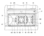
- FIG. 6 is a perspective view showing the structure of the external power input unit 41 in this embodiment
- FIG. 7 is a cross-sectional perspective view showing the structure of the case, connector mounting plate, slide plate, etc. shown in FIG. is there. 8 to 10 are side views showing the structure of the external power supply input unit 41 in the present embodiment.
- the external power supply input unit 41 has a rectangular parallelepiped case 61 mounted on the revolving frame 11 and a connector mounting plate 62 provided on the case 61.
- the connectors 59A, 59B, 59C described above are attached to the connector attachment plate 62 so as to be aligned in the front-rear direction (left-right direction in the figure).
- the lid 63 constituting a part of the left exterior cover 40 described above is attached so as to be pivotable in the vertical direction via a hinge 64 so that the external power input part 41 can be opened and closed.
- the case 61 is provided with a fixed bracket 65, and the lid 63 is provided with a lock mechanism 66 that can be engaged with the fixed bracket 65.
- a pair of bent plates 67A having an L-shaped cross section and extending in the front-rear direction are attached to the lower surface side of the case 61, and a guide groove 68A is formed between the bent plates 67A.
- a pair of bent plates 67B having an L-shaped cross section and extending in the front-rear direction are attached to the upper surface side of the case 61, and a guide groove 68B is formed between the bent plates 67B.
- the slide plates 69A and 69B are slidably inserted into the guide grooves 68A and 68B at their upper and lower ends.
- the slide plates 69A and 69B are supported so as to be slidable in the front-rear direction (in other words, the direction in which the connectors 59A, 59B, and 59C are arranged) without overlapping each other in the plate thickness direction.
- substantially semicircular cutouts 70 are formed on both front and rear sides of the slide plates 69A and 69B.
- the plug 60A of the three-phase AC 200V power supply 49A can be connected to the connector 59A
- the plug 60B of the single-phase AC 100V power supply 49B cannot be connected to the connector 59B
- the plug 60C of the DC 200V power supply 49C cannot be connected to the connector 59C. It is said.
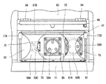
- the connector 58B is opened and the connectors 58C and 58A are shielded by the slide plates 69A and 69B. Is done.
- the plug 60B of the single-phase AC 100V power supply 49B can be connected to the connector 59B
- the plug 60C of the DC 200V power supply 49C cannot be connected to the connector 59C
- the plug 60A of the three-phase AC 200V power supply 49A cannot be connected to the connector 59A. It is said.
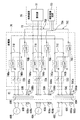
- FIG. 11 is an electric circuit diagram showing the configuration of the switchboard 36 in the present embodiment together with related devices.
- the switchboard 36 has power transmission systems 71A, 71B, 71C connected to connectors 59A, 59B, 59C, respectively.
- Breakers 72A, 72B, 72C (overcurrent protectors) are provided in the power transmission systems 71A, 71B, 71C, respectively.
- the power transmission systems 71 ⁇ / b> A, 71 ⁇ / b> B, 71 ⁇ / b> C are joined to one common system 73 and then connected to the rectifier 51 of the control device 35. Therefore, for example, in the configuration of the related art as shown in FIG. 15 described above, there is a possibility that current flows to a connector to which no external power source is connected via the junction of the power transmission system.
- connector side connection detection terminals 59Aa and 59Ab are provided on the connector 59A, and the plug side connection detection terminals 60Aa and 60Ab. Is provided in the plug 60A. Also, normally open contact type switches (switch relays) 74Aa and 74Ab are provided in the power transmission system 71A, and a relay circuit 75A for controlling these switches 74Aa and 74Ab is provided.
- the plug-side connection detection terminals 60Aa and 60Ab are connected to each other, and the connector-side connection detection terminal 59Ab is connected to a ground potential body.
- the relay circuit 75A has a normally open contact type control relay 76A.
- the coil of the control relay 76 ⁇ / b> A has a negative electrode side connected to the connector side connection detection terminal 59 ⁇ / b> Aa and a positive electrode side connected to the auxiliary power circuit 53 of the control device 35.
- the coils of the switches 74Aa and 74Ab have a negative electrode side connected to the ground potential body and a positive electrode side connected to the auxiliary power circuit 53 via a contact of the control relay 76A. For example, when the connector 59A and the plug 60A of the external power source 49A are connected, the connector side connection detection terminal 59Aa and the plug side connection detection terminal 60Aa are connected, and the connector side connection detection terminal 59Ab and the plug side connection detection are detected.
- the terminal 60Ab is connected, and the negative side of the coil of the control relay 76A is connected to the ground potential body.
- the coil of the control relay 76A is energized, the contact of the control relay 76A is switched from the open state to the closed state, and the coils of the switches 74Aa and 74Ab are energized via this contact, and the switches 74Aa and 74Ab are energized.
- the switches 74Aa and 74Ab are energized.
- connector-side connection detection terminals 59Ba and 59Bb are provided on the connector 59B, and plug-side connection detection terminals 60Ba and 60Bb are provided on the plug 60B. It has been. Further, normally open contact type switches (switch relays) 74Ba and 74Bb are provided in the power transmission system 71B, and a relay circuit 75B for controlling these switches 74Ba and 74Bb is provided.
- the plug-side connection detection terminals 60Ba and 60Bb are connected to each other, and the connector-side connection detection terminal 59Bb is connected to a ground potential body.
- the relay circuit 75B has a normally open contact type control relay 76B.
- the coil of the control relay 76B has a negative electrode side connected to the connector side connection detection terminal 59Ba, and a positive electrode side connected to the auxiliary power circuit 53 of the control device 35.
- the coils of the switches 74Ba and 74Bb have the negative electrode side connected to the ground potential body and the positive electrode side connected to the auxiliary power supply circuit 53 via the contact of the control relay 76B. For example, when the connector 59B and the plug 60B of the external power source 49B are connected, the connector side connection detection terminal 59Ba and the plug side connection detection terminal 60Ba are connected, and the connector side connection detection terminal 59Bb and the plug side connection detection are detected.
- the terminal 60Bb is connected, and the negative side of the coil of the control relay 76B is connected to the ground potential body.
- the coil of the control relay 76B is energized, the contact of the control relay 76B is switched from the open state to the closed state, and the coils of the switches 74Ba and 74Bb are energized via this contact, and the switches 74Ba and 74Bb are energized.
- connector-side connection detection terminals 59Ca and 59Cb are provided on the connector 59C
- plug-side connection detection terminals 60Ca and 60Cb are provided on the plug 60C. It has been.
- normally open contact type switches (switch relays) 74Ca and 74Cb are provided in the power transmission system 71C, and a relay circuit 75C for controlling the switches 74Ca and 74Cb is provided.
- the plug-side connection detection terminals 60Ca and 60Cb are connected to each other, and the connector-side connection detection terminal 59Cb is connected to a ground potential body.
- the relay circuit 75C has a normally open contact type control relay 76C.
- the coil of the control relay 76 ⁇ / b> C has a negative electrode side connected to the connector side connection detection terminal 59 ⁇ / b> Ca, and a positive electrode side connected to the auxiliary power circuit 53 of the control device 35.
- the coils of the switches 74Ca and 74Cb have the negative electrode side connected to the ground potential body and the positive electrode side connected to the auxiliary power supply circuit 53 via the contact of the control relay 76C.
- the connector side connection detection terminal 59Ca and the plug side connection detection terminal 60Ca are connected, and the connector side connection detection terminal 59Cb and the plug side connection detection are detected.
- the terminal 60Cb is connected, and the negative side of the coil of the control relay 76C is connected to the ground potential body.
- the coil of the control relay 76C is energized, the contact of the control relay 76C is switched from the open state to the closed state, and the coils of the switches 74Ca and 74Cb are energized via this contact, and the switches 74Ca and 74Cb are energized.
- the connector-side connection detection terminals 59Aa, 59Ab, 59Ba, 59Bb, 59Ca, 59Cb and the plug-side connection detection terminals 60Aa, 60Ab, 60Ba, 60Bb, 60Ca, 60Cb are plural in the claims.
- a detection unit that detects which one of the connectors is connected to the plug of the external power supply is configured.
- the relay circuits 75A, 75B, and 75C include an opening / closing control unit that controls a switch corresponding to the connector detected by the detection unit among a plurality of switches to be in a closed state and other switches to be in an open state.
- the relay circuits 75A, 75B, and 75C include switches that correspond to the connectors to which the plugs of the external power supply are connected among the switches 74Aa, 74Ab, 74Ba, 74Bb, 74Ca, and 74Cb.
- the switch corresponding to the connector to which the plug of the external power source is not connected is controlled to be in the open state. Thereby, it can prevent that an electric current wraps around the connector to which the external power supply is not connected via the junction part of power transmission system 71A, 71B, 71C.
- FIGS. 1-10 A second embodiment of the present invention will be described with reference to FIGS.
- the same parts as those in the first embodiment are denoted by the same reference numerals, and description thereof will be omitted as appropriate.
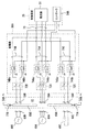
- FIG. 12 is an electric circuit diagram showing the configuration of the switchboard 36A in the present embodiment together with related devices.
- FIG. 13 is a side view showing the arrangement of limit switches in the present embodiment together with the structure of the external power supply input unit 41.
- the case 61 of the external power input unit 41 is provided with limit switches 77A and 77B for detecting the slide positions of the slide plates 69A and 69B, respectively.
- the limit switch 77A detects whether or not the slide plate 69A has reached a predetermined front slide position, and outputs the detection result as a detection signal.
- the limit switch 77B detects whether or not the slide plate 69B has reached a predetermined rear slide position, and outputs the detection result as a detection signal.
- the controller 54A of the controller 35 controls the opening / closing of the switches 74Aa, 74Ab, 74Ba, 74Bb, 74Ca, 74Cb based on the detection signals input from the limit switches 77A, 77B.
- the procedure for opening / closing control of the controller 54A will be described with reference to FIG.
- FIG. 14 is a flowchart showing the processing contents related to the opening / closing control of the controller 54A in the present embodiment.
- Controller 54A determines in step 80 whether or not the battery charging mode is set. For example, when it is not the battery charging mode, the determination at step 80 is not satisfied and the routine goes to step 81. In step 81, since no control signal is output to the coils of all the switches 74Aa, 74Ab, 74Ba, 74Bb, 74Ca, 74Cb, the contacts of all the switches 74Aa, 74Ab, 74Ba, 74Bb, 74Ca, 74Cb are opened. To do. On the other hand, for example, in the battery charging mode, the determination in step 80 is satisfied, and the routine proceeds to step 82.
- step 82 based on the presence / absence of detection signals from the limit switches 77A and 77B, it is determined which of the connectors 59A, 59B and 59C can be connected to the plug of the external power source.
- step 83 a control signal is output to the coil of the switch corresponding to the connector that is determined to be connectable to the plug of the external power source, and the contact of the switch is closed. Further, since the control signal is not output to the coil of the switch corresponding to the other connector, that is, the connector determined to be unable to connect the plug of the external power source, the contact of the switch is opened.
- the connector 59A when there is a detection signal from the limit switch 77A and a detection signal from the limit switch 77B, the connector 59A can be connected to an external power supply plug, and the connectors 59B and 59C can be connected to an external power supply plug. It is determined that it is impossible (see FIGS. 13 and 8 above). Then, a control signal is output to the coils of the switches 74Aa and 74Ab corresponding to the connector 59A, and the contacts of the switches 74Aa and 74Ab are closed.
- the connector 59B can be connected to the plug of the external power supply, and the connectors 59C and 59A cannot be connected to the plug of the external power supply. It is determined that it exists (see FIG. 9 described above). Then, a control signal is output to the coils of the switches 74Ba and 74Bb corresponding to the connector 59B to close the contacts of the switches 74Ba and 74Bb.
- the connector 59C can be connected to an external power plug, and the connectors 59A and 59B cannot be connected to an external power plug. It is determined that it exists (see FIG. 10 described above). And a control signal is output to the coil of switch 74Ca, 74Cb corresponding to the connector 59C, and the contact of switch 74Ca, 74Cb is made into a closed state.
- step 84 a boost command or a step-down command is output to the step-up / down regulator 52 to perform charge control, and then the process proceeds to step 85 to determine whether or not the charge is completed. For example, when the charging is not completed, the determination in step 85 is not satisfied, and the process returns to the above-described step 80 and the same procedure is repeated. For example, when the charging control at step 84 is continued and the charging is completed, the determination at step 85 is satisfied, and the routine proceeds to step 81.
- step 81 since no control signal is output to the coils of all the switches 74Aa, 74Ab, 74Ba, 74Bb, 74Ca, 74Cb, the contacts of all the switches 74Aa, 74Ab, 74Ba, 74Bb, 74Ca, 74Cb are opened. To do.
- the limit switches 76A and 76B constitute a detection unit that detects which one of the plurality of connectors described in the claims is selected for connection with the plug of the external power supply.
- the controller 54A of the control device 35 constitutes an open / close control unit that controls a switch corresponding to the connector detected by the detection unit to a closed state and other switches to an open state among the plurality of switches. To do.
- the controller 54A of the control device 35 determines a connector to which an external power plug can be connected based on detection signals from the limit switches 77A and 77B.
- the switch corresponding to the connector to which the plug of the external power supply can be connected is closed, and the switch corresponding to the connector to which the plug of the external power supply cannot be connected Control the vessel to the open state.
- the controller 54A of the controller 35 switches the switches 74Aa and 74Aa based on the detection signals input from the limit switches 77A and 77B.
- a function opening / closing control unit
- 74Ab, 74Ba, 74Bb, 74Ca, 74Cb has been described as an example.
- the present invention is not limited to this, and various types can be used without departing from the spirit and technical idea of the present invention. Deformation is possible.
- a controller (open / close control unit) that controls opening and closing of the switches 74Aa, 74Ab, 74Ba, 74Bb, 74Ca, and 74Cb based on detection signals input from the limit switches 77A and 77B is referred to as the controller 54 of the control device 35. It may be provided separately. In this case, the same effect as described above can be obtained.
- a battery drive function (battery drive unit) that supplies power from the battery device 38 to the electric motor 32 and power from the external power supply 49 are supplied to the battery device 38.
- the control device 35 having a battery charging function battery charging unit
- the present invention is not limited thereto, and various modifications can be made without departing from the spirit and technical idea of the present invention. That is, the battery driving unit and the battery charging unit may be provided separately.
- the control device 35 supplies the electric power from the three-phase AC 200V power source 49A to the electric motor 32 and drives the electric motor 32 when, for example, a three-phase AC 200V power source 49A is connected by the external power input unit 41.
- An external power supply drive function (external power supply drive unit) may be further provided, and the battery charging mode and the external power supply drive mode may be selectively performed according to the operation of the mode switch.
- the inverter 50 converts the DC power from the rectifier 51 into AC power in accordance with the target rotational speed command from the controller and supplies the AC power to the electric motor 32. That's fine. In such a case, the same effect as described above can be obtained.
- three connectors to which the plug 60A of the three-phase AC 200V power source 49A, the plug 60B of the single-phase AC 100V power source 49B, and the plug 60C of the DC 200V power source 49C can be connected respectively.
- the case where 59A, 59B, and 59C are provided has been described as an example.
- the present invention is not limited to this, and various modifications can be made without departing from the spirit and technical idea of the present invention. That is, for example, two connectors to which two types of external power supplies can be connected may be provided, or four or more connectors to which four or more types of external power sources can be connected may be provided. In these cases, the same effect as described above can be obtained.
- the electric hydraulic excavator is other than the hydraulic actuator for the working device (specifically, the boom hydraulic cylinder 18, the arm hydraulic cylinder 19, and the bucket hydraulic cylinder 20).
- the left and right traveling hydraulic motors 9 and the turning hydraulic motors are provided as the hydraulic actuator
- the present invention is not limited thereto. That is, for example, instead of the left and right traveling hydraulic motors 9, left and right traveling electric motors driven by electric power from the battery device 38 may be provided. Further, for example, instead of the turning hydraulic motor, a turning electric motor driven by electric power from the battery device 38 may be provided. In these cases, the same effect as described above can be obtained.
- the electric hydraulic excavator has been described by way of an example in which the swing type work device 4 is provided.
- the present invention is not limited to this, and an offset type work device is provided. Also good.
- the electric hydraulic excavator has been described by taking the case where the crawler type lower traveling body 1 is provided as an example, the electric hydraulic excavator is not limited thereto, and may be provided with a wheel type lower traveling body. In these cases, the same effect as described above can be obtained.
- the electric hydraulic excavator has been described as an application target of the present invention as an example.
- the present invention is not limited thereto, and it goes without saying that the present invention may be applied to other electric construction machines.
Landscapes
- Engineering & Computer Science (AREA)
- Mining & Mineral Resources (AREA)
- Structural Engineering (AREA)
- General Engineering & Computer Science (AREA)
- Civil Engineering (AREA)
- Mechanical Engineering (AREA)
- Power Engineering (AREA)
- Transportation (AREA)
- Life Sciences & Earth Sciences (AREA)
- Sustainable Energy (AREA)
- Sustainable Development (AREA)
- Operation Control Of Excavators (AREA)
- Charge And Discharge Circuits For Batteries Or The Like (AREA)
- Electric Propulsion And Braking For Vehicles (AREA)
Description
制御装置35のコントローラ54は、例えば、キースイッチ28からの信号によってキースイッチ28がSTART位置に操作されたと判定し、且つ、ロックスイッチ48からの信号の有無によってゲートロックレバー27が乗降阻止位置(下降位置)にあると判定した場合に、バッテリ駆動モードを開始する。
制御装置35のコントローラ54は、例えば、キースイッチ28からの信号によってキースイッチ28がOFF位置にあると判定し、且つ、充電スイッチ30からの信号の有無によって充電スイッチ30がON位置に操作されたと判定した場合に、バッテリ充電モードを開始する。
14 スイング用油圧シリンダ
18 ブーム用油圧シリンダ
19 アーム用油圧シリンダ
20 バケット用油圧シリンダ
32 電動モータ
33 油圧ポンプ
35 制御装置
36,36A 配電盤
38 バッテリ装置
41 外部電源入力部
49 外部電源
49A 三相交流200V電源(外部電源)
49B 単相交流100V電源(外部電源)
49C 直流200V電源(外部電源)
50 インバータ
51 整流器
52 昇降圧器
53 補助電源回路
54,54A コントローラ
55 バッテリコントローラ
56 内部バッテリ
57 バッテリ系統
59A,59B,59C コネクタ
59Aa,59Ab コネクタ側接続検出用端子
59Ba,59Bb コネクタ側接続検出用端子
59Ca,59Cb コネクタ側接続検出用端子
60A,60B,60C プラグ
60Aa,60Ab プラグ側接続検出用端子
60Ba,60Bb プラグ側接続検出用端子
60Ca,60Cb プラグ側接続検出用端子
69A,69B スライド板
71A,71B,71C 送電系統
73 共用系統
74Aa,74Ab 開閉器
74Ba,74Bb 開閉器
74Ca,74Cb 開閉器
75A,75B,75C リレー回路
76A,76B,76C 制御リレー
77A,77B リミットスイッチ
Claims (3)
- 電動モータと、
前記電動モータによって駆動される油圧ポンプと、
前記油圧ポンプから吐出された圧油により駆動される油圧アクチュエータと、
前記電動モータの電力源である内部バッテリと、
複数種類の外部電源のプラグがそれぞれ接続可能な複数のコネクタと、
前記複数のコネクタにそれぞれ接続された複数の送電系統と、
前記複数の送電系統が1つの共用系統を介して接続されたバッテリ充電部とを備え、
前記バッテリ充電部は、前記複数のコネクタのうちのいずれかが前記外部電源のプラグと接続された場合に、前記外部電源から供給された電力を前記内部バッテリに供給する電動式建設機械において、
前記複数の送電系統にそれぞれ設けられ、前記複数のコネクタにそれぞれ対応した複数の開閉器と、
前記複数のコネクタのうちのいずれが前記外部電源のプラグと接続されたか、若しくは前記複数のコネクタのうちのいずれが前記外部電源のプラグと接続するために選択されたかを検出する検出部と、
前記複数の開閉器のうち、前記検出部で検出されたコネクタに対応する開閉器を閉状態に、それ以外の開閉器を開状態に制御する開閉制御部とを備えたことを特徴とする電動式建設機械。 - 請求項1記載の電動式建設機械において、
前記検出部は、前記複数のコネクタにそれぞれ設けられ、前記外部電源のプラグに設けられたプラグ側接続検出用端子と接続されるコネクタ側接続検出用端子を有し、
前記開閉制御部は、前記コネクタと前記開閉器の組合せに対応した制御リレーをそれぞれ有する複数のリレー回路であり、
前記複数のリレー回路は、前記複数のコネクタのうちのいずれかと前記外部電源のプラグが接続された場合に、対応する前記コネクタ側接続検出用端子と前記プラグ側接続検出用端子の接続によって対応する前記制御リレーのコイルが通電して、対応する前記制御リレーの接点が閉状態に切換わり、この接点を介して対応する前記開閉器のコイルが通電して、対応する前記開閉器の接点が閉状態に切換わるように構成されたことを特徴とする電動式建設機械。 - 請求項1記載の電動式建設機械において、
前記複数のコネクタのうちのいずれかを前記外部電源のプラグと接続可能なように選択的に開放しつつ、残りのコネクタを前記外部電源のプラグと接続不能なように遮蔽するスライド板を設けており、
前記検出部は、前記スライド板のスライド位置を検出するリミットスイッチを有し、
前記開閉制御部は、前記複数の開閉器のうち、前記リミットスイッチの検出結果に基づき前記外部電源のプラグが接続可能と判定したコネクタに対応する開閉器を閉状態に、それ以外の開閉器を開状態に制御するコントローラであることを特徴とする電動式建設機械。
Priority Applications (4)
| Application Number | Priority Date | Filing Date | Title |
|---|---|---|---|
| CN201380044080.4A CN104583497B (zh) | 2012-08-21 | 2013-06-19 | 电动式工程机械 |
| EP13831047.9A EP2889432B1 (en) | 2012-08-21 | 2013-06-19 | Electric construction machine |
| KR1020157004367A KR101711766B1 (ko) | 2012-08-21 | 2013-06-19 | 전동식 건설 기계 |
| US14/422,196 US9889750B2 (en) | 2012-08-21 | 2013-06-19 | Electric construction machine |
Applications Claiming Priority (2)
| Application Number | Priority Date | Filing Date | Title |
|---|---|---|---|
| JP2012-182534 | 2012-08-21 | ||
| JP2012182534A JP5837863B2 (ja) | 2012-08-21 | 2012-08-21 | 電動式建設機械 |
Publications (1)
| Publication Number | Publication Date |
|---|---|
| WO2014030415A1 true WO2014030415A1 (ja) | 2014-02-27 |
Family
ID=50149733
Family Applications (1)
| Application Number | Title | Priority Date | Filing Date |
|---|---|---|---|
| PCT/JP2013/066831 Ceased WO2014030415A1 (ja) | 2012-08-21 | 2013-06-19 | 電動式建設機械 |
Country Status (6)
| Country | Link |
|---|---|
| US (1) | US9889750B2 (ja) |
| EP (1) | EP2889432B1 (ja) |
| JP (1) | JP5837863B2 (ja) |
| KR (1) | KR101711766B1 (ja) |
| CN (2) | CN106284452B (ja) |
| WO (1) | WO2014030415A1 (ja) |
Cited By (1)
| Publication number | Priority date | Publication date | Assignee | Title |
|---|---|---|---|---|
| JP2020051233A (ja) * | 2018-09-28 | 2020-04-02 | 株式会社小松製作所 | 電動式建設機械 |
Families Citing this family (26)
| Publication number | Priority date | Publication date | Assignee | Title |
|---|---|---|---|---|
| JP5692539B2 (ja) * | 2012-09-18 | 2015-04-01 | 株式会社豊田自動織機 | 産業車両 |
| US9484602B1 (en) * | 2013-08-22 | 2016-11-01 | OSC Manufacturing & Equipment Services, Inc. | Light tower having a battery housing |
| US10131042B2 (en) | 2013-10-21 | 2018-11-20 | Milwaukee Electric Tool Corporation | Adapter for power tool devices |
| JP6401241B2 (ja) * | 2014-03-06 | 2018-10-10 | 住友建機株式会社 | ショベル |
| JP6596458B2 (ja) * | 2017-03-13 | 2019-10-23 | 株式会社日立建機ティエラ | 電動式油圧作業機械の油圧駆動装置 |
| JP2019190104A (ja) * | 2018-04-24 | 2019-10-31 | ヤンマー株式会社 | 電動式作業機械 |
| JP7053360B2 (ja) * | 2018-04-24 | 2022-04-12 | ヤンマーパワーテクノロジー株式会社 | 電動式作業機械 |
| KR102027230B1 (ko) * | 2018-06-27 | 2019-10-02 | 대모 엔지니어링 주식회사 | 전자식 유압브레이커의 충전시스템 |
| JP6944426B2 (ja) * | 2018-09-05 | 2021-10-06 | 株式会社日立建機ティエラ | 電動式建設機械 |
| JP7175145B2 (ja) * | 2018-09-14 | 2022-11-18 | 株式会社小松製作所 | 電動式建設機械 |
| JP7360581B2 (ja) * | 2019-04-04 | 2023-10-13 | コベルコ建機株式会社 | 作業機械用操作機構、及び、それを備えた作業機械 |
| KR102702058B1 (ko) * | 2019-09-10 | 2024-09-02 | 에이치디현대인프라코어 주식회사 | 전기굴삭기의 전력공급장치 |
| FR3113262B1 (fr) * | 2020-08-08 | 2023-03-10 | Baptiste Hanser | Engin de chantier électrifié supportant un élément d’énergie auxiliaire. |
| US11890953B2 (en) * | 2021-03-29 | 2024-02-06 | Deere & Company | Electric accessory interface for work vehicle |
| JPWO2022210391A1 (ja) * | 2021-03-31 | 2022-10-06 | ||
| CN117120692A (zh) * | 2021-03-31 | 2023-11-24 | 住友建机株式会社 | 挖土机 |
| US12587226B2 (en) * | 2021-06-10 | 2026-03-24 | Rosemount Inc. | Wireless discrete input/output with external power option |
| JP7519983B2 (ja) * | 2021-12-24 | 2024-07-22 | 株式会社クボタ | 電動作業車 |
| JP2023149027A (ja) * | 2022-03-30 | 2023-10-13 | 住友建機株式会社 | ショベル |
| JP7733812B2 (ja) * | 2022-03-31 | 2025-09-03 | 株式会社日立建機ティエラ | 電動作業機械 |
| JP7846032B2 (ja) * | 2023-02-27 | 2026-04-14 | 株式会社竹内製作所 | 作業用車両 |
| US12425062B2 (en) | 2023-03-06 | 2025-09-23 | Rosemount Inc. | Load adapter module for wireless discrete input/output field device |
| DE102023202728A1 (de) * | 2023-03-27 | 2024-10-02 | Scheuerle Fahrzeugfabrik Gmbh | Energieversorgungseinheit, System und Schwerlast-Modulfahrzeug |
| JP2025142999A (ja) * | 2024-03-18 | 2025-10-01 | ヤンマーホールディングス株式会社 | 作業機械 |
| EP4631771A1 (de) * | 2024-04-12 | 2025-10-15 | Wimmer Felstechnik Gesellschaft m.b.H. | Baggersystem, insbesondere tunnelvortriebssystem |
| CN118621862A (zh) * | 2024-06-21 | 2024-09-10 | 徐州徐工挖掘机械有限公司 | 一种继电控制系统及方法 |
Citations (4)
| Publication number | Priority date | Publication date | Assignee | Title |
|---|---|---|---|---|
| JP2009215855A (ja) * | 2008-03-13 | 2009-09-24 | Hitachi Constr Mach Co Ltd | 作業機械 |
| JP2009278706A (ja) * | 2008-05-12 | 2009-11-26 | Toyota Motor Corp | 電動車両の充電装置 |
| JP2011172408A (ja) * | 2010-02-19 | 2011-09-01 | Hitachi Constr Mach Co Ltd | 電動式建設機械 |
| JP2012001889A (ja) | 2010-06-14 | 2012-01-05 | Hitachi Constr Mach Co Ltd | 電動式建設機械 |
Family Cites Families (12)
| Publication number | Priority date | Publication date | Assignee | Title |
|---|---|---|---|---|
| JP4961321B2 (ja) * | 2007-10-18 | 2012-06-27 | 鹿島道路株式会社 | バッテリ駆動建設機械を用いた施工方法 |
| US7827787B2 (en) * | 2007-12-27 | 2010-11-09 | Deere & Company | Hydraulic system |
| JP5319236B2 (ja) * | 2008-10-22 | 2013-10-16 | 日立建機株式会社 | 電源装置および作業機械 |
| JP5185082B2 (ja) * | 2008-11-18 | 2013-04-17 | 日立建機株式会社 | 電動式油圧作業機械 |
| JP5412999B2 (ja) * | 2009-07-02 | 2014-02-12 | トヨタ自動車株式会社 | 電動車両 |
| US8513837B2 (en) * | 2009-07-28 | 2013-08-20 | Parker-Hannifin Corporation | Electrical interrupt system and method for use in a hybrid system |
| CN102021921B (zh) * | 2009-09-18 | 2012-05-23 | 鞍钢集团矿业公司 | 井下双能源铲运机供电设备及其供电方法 |
| JP5527883B2 (ja) * | 2009-12-08 | 2014-06-25 | 住友建機株式会社 | 建設機械 |
| JP2011122364A (ja) * | 2009-12-11 | 2011-06-23 | Fuji Heavy Ind Ltd | 作業車両 |
| EP2520456B1 (en) * | 2009-12-28 | 2019-02-27 | Toyota Jidosha Kabushiki Kaisha | Vehicle |
| US20110198141A1 (en) * | 2010-02-16 | 2011-08-18 | Genie Industries, Inc. | Hydraulic electric hybrid drivetrain |
| JP5884699B2 (ja) * | 2012-09-28 | 2016-03-15 | 三菱自動車工業株式会社 | トラック形電動車両の充電コネクタ収容装置 |
-
2012
- 2012-08-21 JP JP2012182534A patent/JP5837863B2/ja active Active
-
2013
- 2013-06-19 CN CN201610907391.4A patent/CN106284452B/zh not_active Expired - Fee Related
- 2013-06-19 US US14/422,196 patent/US9889750B2/en active Active
- 2013-06-19 WO PCT/JP2013/066831 patent/WO2014030415A1/ja not_active Ceased
- 2013-06-19 CN CN201380044080.4A patent/CN104583497B/zh active Active
- 2013-06-19 EP EP13831047.9A patent/EP2889432B1/en active Active
- 2013-06-19 KR KR1020157004367A patent/KR101711766B1/ko not_active Expired - Fee Related
Patent Citations (4)
| Publication number | Priority date | Publication date | Assignee | Title |
|---|---|---|---|---|
| JP2009215855A (ja) * | 2008-03-13 | 2009-09-24 | Hitachi Constr Mach Co Ltd | 作業機械 |
| JP2009278706A (ja) * | 2008-05-12 | 2009-11-26 | Toyota Motor Corp | 電動車両の充電装置 |
| JP2011172408A (ja) * | 2010-02-19 | 2011-09-01 | Hitachi Constr Mach Co Ltd | 電動式建設機械 |
| JP2012001889A (ja) | 2010-06-14 | 2012-01-05 | Hitachi Constr Mach Co Ltd | 電動式建設機械 |
Non-Patent Citations (1)
| Title |
|---|
| See also references of EP2889432A4 |
Cited By (3)
| Publication number | Priority date | Publication date | Assignee | Title |
|---|---|---|---|---|
| JP2020051233A (ja) * | 2018-09-28 | 2020-04-02 | 株式会社小松製作所 | 電動式建設機械 |
| WO2020066048A1 (ja) * | 2018-09-28 | 2020-04-02 | 株式会社小松製作所 | 電動式建設機械 |
| JP7204401B2 (ja) | 2018-09-28 | 2023-01-16 | 株式会社小松製作所 | 電動式建設機械 |
Also Published As
| Publication number | Publication date |
|---|---|
| US20150231974A1 (en) | 2015-08-20 |
| CN104583497A (zh) | 2015-04-29 |
| US9889750B2 (en) | 2018-02-13 |
| EP2889432A1 (en) | 2015-07-01 |
| KR101711766B1 (ko) | 2017-03-03 |
| JP2014040718A (ja) | 2014-03-06 |
| JP5837863B2 (ja) | 2015-12-24 |
| EP2889432A4 (en) | 2016-03-30 |
| EP2889432B1 (en) | 2018-01-03 |
| CN104583497B (zh) | 2017-02-22 |
| CN106284452B (zh) | 2018-10-23 |
| KR20150038169A (ko) | 2015-04-08 |
| CN106284452A (zh) | 2017-01-04 |
Similar Documents
| Publication | Publication Date | Title |
|---|---|---|
| JP5837863B2 (ja) | 電動式建設機械 | |
| JP6038934B2 (ja) | 建設機械 | |
| JP5778752B2 (ja) | 電動式建設機械 | |
| JP5662900B2 (ja) | 電動式建設機械 | |
| JP6944426B2 (ja) | 電動式建設機械 | |
| US8700246B2 (en) | Electrically-operated construction machine | |
| EP2700755B1 (en) | Electromotive drive device of construction machine | |
| JP2013129976A (ja) | 電動式建設機械 | |
| JP2020051065A (ja) | 電動式建設機械 | |
| JP7852908B2 (ja) | 電動ショベル | |
| US20250250769A1 (en) | Work machine | |
| JP2025142999A (ja) | 作業機械 | |
| JP2023134163A (ja) | 電動ショベル | |
| EP4624675A1 (en) | Working machine |
Legal Events
| Date | Code | Title | Description |
|---|---|---|---|
| 121 | Ep: the epo has been informed by wipo that ep was designated in this application |
Ref document number: 13831047 Country of ref document: EP Kind code of ref document: A1 |
|
| WWE | Wipo information: entry into national phase |
Ref document number: 2013831047 Country of ref document: EP |
|
| ENP | Entry into the national phase |
Ref document number: 20157004367 Country of ref document: KR Kind code of ref document: A |
|
| WWE | Wipo information: entry into national phase |
Ref document number: 14422196 Country of ref document: US |
|
| NENP | Non-entry into the national phase |
Ref country code: DE |