WO2014045360A1 - 質量分析装置 - Google Patents
質量分析装置 Download PDFInfo
- Publication number
- WO2014045360A1 WO2014045360A1 PCT/JP2012/074002 JP2012074002W WO2014045360A1 WO 2014045360 A1 WO2014045360 A1 WO 2014045360A1 JP 2012074002 W JP2012074002 W JP 2012074002W WO 2014045360 A1 WO2014045360 A1 WO 2014045360A1
- Authority
- WO
- WIPO (PCT)
- Prior art keywords
- voltage
- mass
- conversion dynode
- mass spectrometer
- ions
- Prior art date
- Legal status (The legal status is an assumption and is not a legal conclusion. Google has not performed a legal analysis and makes no representation as to the accuracy of the status listed.)
- Ceased
Links
Images



Classifications
-
- G—PHYSICS
- G01—MEASURING; TESTING
- G01N—INVESTIGATING OR ANALYSING MATERIALS BY DETERMINING THEIR CHEMICAL OR PHYSICAL PROPERTIES
- G01N30/00—Investigating or analysing materials by separation into components using adsorption, absorption or similar phenomena or using ion-exchange, e.g. chromatography or field flow fractionation
- G01N30/02—Column chromatography
- G01N30/62—Detectors specially adapted therefor
- G01N30/72—Mass spectrometers
- G01N30/7233—Mass spectrometers interfaced to liquid or supercritical fluid chromatograph
-
- H—ELECTRICITY
- H01—ELECTRIC ELEMENTS
- H01J—ELECTRIC DISCHARGE TUBES OR DISCHARGE LAMPS
- H01J49/00—Particle spectrometers or separator tubes
- H01J49/0027—Methods for using particle spectrometers
-
- H—ELECTRICITY
- H01—ELECTRIC ELEMENTS
- H01J—ELECTRIC DISCHARGE TUBES OR DISCHARGE LAMPS
- H01J49/00—Particle spectrometers or separator tubes
- H01J49/02—Details
- H01J49/025—Detectors specially adapted to particle spectrometers
-
- H—ELECTRICITY
- H01—ELECTRIC ELEMENTS
- H01J—ELECTRIC DISCHARGE TUBES OR DISCHARGE LAMPS
- H01J49/00—Particle spectrometers or separator tubes
- H01J49/02—Details
- H01J49/04—Arrangements for introducing or extracting samples to be analysed, e.g. vacuum locks; Arrangements for external adjustment of electron- or ion-optical components
- H01J49/0431—Arrangements for introducing or extracting samples to be analysed, e.g. vacuum locks; Arrangements for external adjustment of electron- or ion-optical components for liquid samples
-
- H—ELECTRICITY
- H01—ELECTRIC ELEMENTS
- H01J—ELECTRIC DISCHARGE TUBES OR DISCHARGE LAMPS
- H01J49/00—Particle spectrometers or separator tubes
- H01J49/02—Details
- H01J49/10—Ion sources; Ion guns
Definitions
- the present invention relates to a mass spectrometer, and more particularly, to a mass spectrometer using an ion detector in which a conversion dynode and a secondary electron multiplier are combined.
- a secondary electron multiplier is often used as a detector for detecting ions (see Patent Document 1).
- the secondary electron multiplier has a multi-stage dynode, and when ions are incident, the secondary electron emitted from the first stage dynode is repeatedly multiplied. Then, the increased secondary electrons are incident on the collector and converted into a current signal, which is taken out as a detection signal.
- a conversion dynode to which a high voltage is applied is placed in front of the secondary electron multiplier, and the secondary radiated in response to the ions incident on this conversion dynode.
- a technique is often employed in which electrons are detected by being incident on a secondary electron multiplier. Since the detection sensitivity increases as the voltage applied to the conversion dynode increases, the voltage applied to the conversion dynode (hereinafter referred to as “CD voltage”) is usually set as high as possible within a range in which abnormal discharge does not occur. For example, as disclosed in Patent Document 2, it is possible to lower the gain by lowering the CD voltage when there is a possibility that the detector is saturated due to too much ion amount. Is kept constant.
- JP 2000-357487 A Japanese Patent No. 4858614
- the mass spectrometer using the combination of the conversion dynode and the secondary electron multiplier as described above as an ion detector has the following problems.
- an atmospheric pressure ion source such as an electrospray ionization method (ESI) or an atmospheric pressure chemical ionization method (APCI) is used. Only the ions are desorbed from the solvent (mobile phase) and introduced into a mass analyzer such as a quadrupole mass filter. Normally, the solvent is vaporized and removed by the evacuation action of the vacuum pump, but cannot be removed if the solvent is difficult to vaporize or if the solvent droplets generated by the atmospheric pressure ion source are large. Solvent droplets may be introduced into the mass spectrometer. For example, when water is used as the mobile phase of a liquid chromatograph (LC), water is much less likely to vaporize than an organic solvent, and thus water droplets are introduced into the mass spectrometer.
- LC liquid chromatograph
- the CD voltage is generally set as high as possible in order to increase the detection sensitivity for high mass ions.
- noise may increase, and the CD voltage may be increased.
- the effect of improving the signal intensity is not seen with high mass ions at low mass ions, so there was also a possibility that the SN ratio of the detection signal would be lowered when the CD voltage was increased.
- the present invention has been made to solve these problems.
- a mass spectrometer using an ion detector in which a conversion dynode and a secondary electron multiplier are combined, the SN ratio of a detection signal is improved.
- the purpose is to improve analysis accuracy.
- the present invention provides an ion source that ionizes components in a sample, a mass analyzer that separates ions generated in the ion source according to a mass-to-charge ratio, and the mass analysis.
- An ion detector having a conversion dynode for converting ions into electrons and a secondary electron multiplier for detecting the ions separated by electrons, and a secondary electron multiplier for detecting ions separated by the detector
- the voltage applied to the conversion dynode by the voltage application means is changed in a plurality of stages, and each time a different voltage is applied to the conversion dynode, the noise signal under the analysis conditions at that time and the target component Analysis execution means for obtaining a detection signal for ions derived from
- Optimum voltage setting means for determining the voltage to be It is characterized by having.
- the analysis executing means controls the voltage applying means so that a plurality of predetermined voltages are sequentially applied to the conversion dynode. In parallel with this, every time the applied voltage is switched, the analysis execution means obtains a noise signal under the analysis conditions at that time and a detection signal for ions derived from the target component.
- the conversion efficiency from ions to electrons at the conversion dynode changes. Therefore, even if the amount of ions derived from the target component incident on the ion detector is constant, the detection signal Will change.
- the applied voltage to the conversion dynode is different, the intensity of the electric field around the conversion dynode changes, and The production efficiency of undesired ions also changes. Therefore, when the voltage applied to the conversion dynode is different, the level of the noise signal also changes.
- the optimum voltage setting means calculates the S / N ratio based on the level of the noise signal and the level of the detection signal obtained for each different applied voltage by executing actual analysis. Then, based on the calculation result, an applied voltage that provides the best or close S / N ratio is found and determined as the optimum voltage to be applied to the conversion dynode when analyzing the target component. Thereby, from the viewpoint of the SN ratio, an appropriate conversion dynode voltage can be obtained in analyzing the target component.
- the noise signal which is a problem in the mass spectrometer according to the present invention that is, the noise signal whose level fluctuates depending on the conversion dynode voltage, is caused by a solvent droplet that reaches the conversion dynode without being removed on the path from the ion source to the conversion dynode.
- the present invention is particularly useful for a mass spectrometer equipped with an atmospheric pressure ion source that ionizes components in a liquid sample.
- the atmospheric pressure ion source includes an electrospray ion source, an atmospheric pressure chemical ion source, an atmospheric pressure photoion source, and the like.
- the mass spectrometer according to the present invention preferably has a configuration in which a liquid sample separated by a liquid chromatograph is introduced into the atmospheric pressure ion source.
- the analysis conditions include at least the type of mobile phase used in the liquid chromatograph and the flow rate (or flow rate) of the mobile phase. That is, the analysis execution means is derived from the same target component as the noise signal while changing the conversion dynode voltage in a plurality of stages under the condition that at least the mobile phase is the same type and the flow rate (or flow velocity) of the mobile phase is the same. And a detection signal for each ion.
- liquid chromatographs it is possible to temporally separate multiple target components contained in a sample, so multiple conversion dynode voltages at the timing when multiple target components elute (that is, during retention time).
- the detection signal By obtaining the detection signal under the above, it is possible to obtain a conversion dynode voltage that is optimal or close to the S / N ratio for each target component.
- any target component can be detected with a high S / N ratio by switching the conversion dynode voltage for each target component. can do.
- each purpose is set so that a time longer than the time required for switching the conversion dynode voltage (not only switching the voltage but also including the time required for the detection signal to stabilize immediately after the switching) is provided during the actual measurement time. If the conditions for SIM measurement (selection ion monitoring measurement) or MRM measurement (multiple reaction monitoring measurement) for ions derived from components are set, the conversion dynode voltage for each ion having a different mass-to-charge ratio is also used in the SIM measurement and MRM measurement. Can be switched. Thereby, any target component can be detected with a high S / N ratio.
- the S / N ratio of the ion detection signal can be improved as compared with the prior art, thereby enabling highly accurate and sensitive mass analysis.
- the noise signal level derived from a droplet is large, and the mass-to-charge ratio of the target component ion is small when the mobile phase flow rate is large (typically 1 mL / min or more) (typically In the case of m / z 200 or less), the noise reduction effect by lowering the conversion dynode voltage is remarkable, while the reduction of the ionic strength is small, so that a large SN ratio improvement effect can be expected.
- FIG. 1 is an overall configuration diagram of a liquid chromatograph mass spectrometer (LC / MS) of the present embodiment
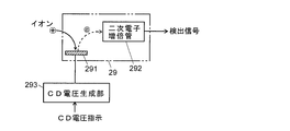
- FIG. 2 is a configuration diagram of an ion detector in FIG.
- the LC / MS of this embodiment includes an LC unit 1 and an MS unit 2.
- the mobile phase stored in the mobile phase container 10 is sent to the column 13 at a substantially constant flow rate by the liquid feed pump 11.
- the sample liquid rides on the flow of the mobile phase and is sent to the column 13, and various components contained in the sample liquid pass through the column 13 in the time direction. Separated and eluted from column 13 outlet.
- MS section 2 has a multi-stage differential exhaust system configuration equipped with an electrospray ion source which is one of atmospheric pressure ion sources.
- the liquid sample sent from the outlet of the column 13 of the LC unit 1 is electrostatically sprayed from the spray nozzle 21 of the electrospray ion source into the ionization chamber 20 which is a substantially atmospheric pressure atmosphere.
- the sprayed charged droplets are brought into contact with the surrounding atmosphere and are refined, and the components contained in the droplets are ionized in the process of vaporizing the solvent in the droplets.
- the ions derived from the sample components thus generated and fine droplets in which the solvent is not completely vaporized enter and mix together, and are sucked into the desolvation tube 22 by the differential pressure across the desolvation tube 22, and the first intermediate It is sent to the vacuum chamber 23.
- the desolvation tube 22 is heated, and the vaporization of the solvent in the droplets is also promoted in the desolvation tube 22, whereby ionization proceeds.
- the ions are maintained in a high vacuum atmosphere via a first ion guide 24 disposed in the first intermediate vacuum chamber 23 and a second ion guide 26 disposed in the second intermediate vacuum chamber 25 of the next stage. It is sent to the analysis room 27.
- the detection signal output from the ion detector 29 is input to the data processing unit 3 including the A / D converter 31 and the like, and the data processing unit 3 performs, for example, mass spectrum, mass chromatogram, total ion based on the obtained data. Create chromatograms.
- the analysis control unit 4 performs LC / MS analysis by controlling the LC unit 1, the MS unit 2, and the data processing unit 3.
- the central control unit 5 provided with the operation unit 6 and the display unit 7 serves as a user interface and executes general commands and control related to analysis.
- At least some of the functions of the data processing unit 3 and the analysis control unit 4 are realized by executing dedicated control / processing software installed in the personal computer on the computer. Can be.
- the data processing unit 3 includes a data collection unit 32, an SN ratio calculation unit 33, and an optimum CD voltage determination unit 34 as functional blocks, and the analysis control unit 4 includes functional blocks.
- the analysis control unit 4 includes functional blocks.
- a CD voltage optimization control unit 41 and an optimal CD voltage storage unit 42 As a CD voltage optimization control unit 41 and an optimal CD voltage storage unit 42.
- the ion detector 29 includes a conversion dynode 291 that converts ions into electrons, a multistage dynode (not shown) that multiplies electrons, and a collector (not shown) that converts electrons into a current signal. And a predetermined high DC voltage is applied to the conversion dynode 291 from the CD voltage generator 293 as a CD voltage. Note that a DC voltage is also applied to the secondary electron multiplier 292, but the functional blocks for that purpose are not shown here.
- the value of the CD voltage applied to the conversion dynode 291 is fixed.
- the value of the CD voltage is optimized according to the analysis conditions and the like. More specifically, the CD voltage is optimized so that the S / N ratio of the detection signal is the best (or a state close to it) when detecting ions derived from the target component.
- control and processing for optimizing the CD voltage will be described.
- Analysis conditions include LC separation conditions such as the flow rate (or flow rate) of the mobile phase in the LC unit 1, the composition of the mobile phase (solvent), the gradient conditions, and the retention time of the target component in the sample (if known)
- the retention time of the target component to be analyzed in the MS unit 2 when known, the mass-to-charge ratio m / z of ions derived from the target component, and the like are included.
- LC / MS analysis in the scan measurement mode is performed in advance to determine the mass-to-charge ratio of ions derived from the target component. Find it.
- the CD voltage optimization control unit 41 starts control of each unit in order to execute the CD optimization process in response to a command from the central control unit 5.
- the LC unit 1 is controlled to perform a plurality of LC analyzes on the same target sample in accordance with the LC separation conditions set in advance, while a CD voltage is predetermined for each LC / MS analysis.
- the CD voltage generation unit 293 of the MS unit 2 is controlled so as to sequentially change the values to a plurality of levels.
- the CD voltage is changed in five stages of ⁇ 1 kV, ⁇ 2 kV, ⁇ 3 kV, ⁇ 5 kV, and ⁇ 6 kV, but the voltage value and the number of stages of change can be appropriately changed.
- the detection target is a positive ion
- the polarity of the CD voltage is negative.
- the detection target is a negative ion
- the polarity of the CD voltage is positive.
- the CD voltage generation unit 293 first applies a CD voltage of ⁇ 1 kV having the smallest absolute voltage value to the conversion dynode 291.
- a target sample is injected from the injector 12 into the mobile phase fed by the liquid feed pump 11, and the sample is fed into the column 13.
- the MS unit 2 performs mass analysis on ions derived from the target component contained in the liquid sample eluted from the outlet of the column 13 under the condition of the CD voltage.
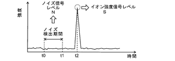
- the mass chromatogram of the mass-to-charge ratio of ions derived from the target component is as shown in FIG. That is, for a while after the sample injection, the target component is not contained in the liquid sample eluted from the column 13, so that the ionic strength is kept low.
- a liquid sample containing the target component starts to be introduced into the spray nozzle 21, so that ions derived from the target component generated mainly in the ionization chamber 20 enter the quadrupole mass filter 28. It is introduced and passes through the quadrupole mass filter 28 and reaches the ion detector 29. Thereby, as shown in FIG. 3, a peak of ionic strength corresponding to the content of the target component appears on the mass chromatogram.
- the liquid sample introduced into the spray nozzle 21 contains components such as impurities other than the target component, ions derived from the component are generated, but these ions do not pass through the quadrupole mass filter 28. There is no effect on the detection signal from the ion detector 29. However, when the solvent in the droplet sprayed from the spray nozzle 21 is not sufficiently vaporized and the solvent droplet having no electric charge is directly introduced into the quadrupole mass filter 28, the droplet proceeds straight as it is. To the ion detector 29. Since a high voltage is applied to the conversion dynode 291 and a strong electric field is formed around the conversion dynode 291, when a droplet enters the electric field, it is ionized by an ionization action. When the unwanted ions generated here are incident on the conversion dynode 291, electrons are emitted, so that noise caused by solvent droplets is generated in the detection signal of the ion detector 29.
- the data collection unit 32 collects noise data in an appropriate period from the start of analysis until the target component starts to elute. For example, as shown in FIG. 3, a period (t0 to t1) starting from a time t0 when a predetermined time has elapsed from the analysis start time and ending at a time t1 that is a predetermined time earlier than the holding time t2 is a noise data collection period. During this time, data obtained by digitizing the detection signal output from the ion detector 29 by the A / D converter 31 is collected. The data collection unit 32 also collects data indicating the maximum ion intensity in the vicinity of the holding time t2. The noise data collection period can be set as appropriate as long as ions derived from the target component do not exist.
- the SN ratio calculation unit 33 calculates the noise signal level N based on a plurality of data collected during the noise data collection period.
- the noise signal level calculation method may be various methods conventionally used. Then, the SN ratio calculation unit 33 calculates the SN ratio from the ion intensity signal level S and the noise signal level N obtained from the data indicating the maximum ion intensity, and temporarily associates this with the CD voltage at that time. To remember.
- the CD voltage generator 293 changes the CD voltage applied to the conversion dynode 291 to ⁇ 2 kV. Then, similarly to the LC / MS analysis under the condition where the CD voltage is ⁇ 1 kV, the target sample is injected into the mobile phase under the predetermined LC separation condition and separated by the column 13, and the MS section 2, mass analysis is performed on ions derived from the target component contained in the liquid sample eluted from the outlet of the column 13 under the condition of the CD voltage.
- the data collection unit 32 and the SN ratio calculation unit 33 collect data based on the detection signal obtained by the ion detector 29, and calculate and store the SN ratio under the CD voltage at that time.
- the S / N ratios for the ions derived from the target component corresponding to the five levels of the CD voltage are obtained. Even if the LC separation conditions are the same and the ions to be analyzed are the same, if the CD voltage is different, the generation efficiency of undesired ions around the conversion dynode 291 changes, so the noise signal level N is different. Of course, if the CD voltage is different, the conversion efficiency from ions to electrons in the conversion dynode 291 also changes, so that the ion intensity signal level S for ions derived from the target component also differs.
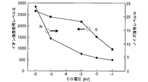
- FIG. 4 is a diagram showing an example of the result of actual measurement of the ion intensity signal level S and the noise signal level N for a certain ion under a predetermined LC separation condition
- FIG. 5 is an SN calculated from the result of FIG. It is a figure which shows the relationship between ratio and CD voltage.
- the S / N ratio is highest when the CD voltage is ⁇ 3 kV, and the S / N ratio decreases even if the CD voltage decreases or increases.
- the optimum CD voltage determination unit 3 reads out and compares the SN ratios stored corresponding to the respective CD voltages as described above after the completion of all analysis, and the SN ratio becomes maximum. Find the CD voltage. Then, it is determined that the found CD voltage is the optimum CD voltage according to the analysis conditions at that time, the mass-to-charge ratio of ions, and the like, and is stored in the optimum CD voltage storage unit 42 of the analysis control unit 4. Subsequently, when performing LC / MS analysis of the same target sample under the same analysis conditions, the analysis control unit 4 instructs the CD voltage generation unit 293 about the CD voltage stored in the optimum CD voltage storage unit 42, and Analysis is performed under the CD voltage. As a result, a detection signal can be obtained for the target component in the target sample in a state where the S / N ratio is the best or close to it, so that highly accurate and sensitive analysis can be performed.
- FIG. 6 is a diagram showing a comparison between the mass chromatogram (a) actually measured with the CD voltage fixed at ⁇ 6 kV and the mass chromatogram (b) obtained after executing the above-described CD voltage optimization processing. is there. Since the CD voltage is set to ⁇ 3 kV by the CD voltage optimization process, the SN ratio is improved from 102 to 364. As described above, according to the LC / MS of the present embodiment, a detection signal with a good S / N ratio can be obtained by appropriately adjusting the CD voltage in accordance with the analysis conditions at that time and the mass-to-charge ratio of the ions to be analyzed. You will be able to get
- the CD with the maximum SN ratio or a state close to that for each analysis condition including the LC separation condition and each mass-to-charge ratio of the ion to be analyzed It is necessary to search for the voltage. Therefore, when the analysis conditions are changed or when the mass-to-charge ratio of ions to be analyzed is different, it is basically necessary to search for the optimum CD voltage again.
- the target sample includes one target component.
- each target component separated in the time direction in the LC unit 1 is provided.
- the CD voltage switching time including the waiting time until the switched voltage is stabilized when switching the CD voltage is about 15 to 20 msec. Accordingly, if a standby time of about 15 to 20 msec is sandwiched between actual measurement times (ion detection times), it is possible to sequentially obtain ion intensities for a plurality of stages of CD voltages.
- the target component is eluted over a relatively long time, and in particular, the state in which the target component concentration in the liquid sample is at the same level continues for a certain period of time (that is, mass chromatogram If the peak top of the upper peak is broad), the CD voltage is sequentially switched in a plurality of stages during a period in which the target component concentration is approximately the same, and an ion intensity signal corresponding to each CD voltage is acquired.
- the time required for the CD voltage optimization process can be shortened and the amount of sample to be used Less.
- the present invention is applied to LC / MS.
- the present invention can also be applied to a mass spectrometer that does not include component separation means such as LC.
- component separation means such as LC.
Landscapes
- Chemical & Material Sciences (AREA)
- Analytical Chemistry (AREA)
- Physics & Mathematics (AREA)
- Engineering & Computer Science (AREA)
- Plasma & Fusion (AREA)
- Health & Medical Sciences (AREA)
- Life Sciences & Earth Sciences (AREA)
- Biochemistry (AREA)
- General Health & Medical Sciences (AREA)
- General Physics & Mathematics (AREA)
- Immunology (AREA)
- Pathology (AREA)
- Other Investigation Or Analysis Of Materials By Electrical Means (AREA)
- Electron Tubes For Measurement (AREA)
Description
本発明は質量分析装置に関し、さらに詳しくは、コンバージョンダイノードと二次電子増倍管とを組み合わせたイオン検出器を利用した質量分析装置に関する。
質量分析装置において、イオンを検出する検出器としては二次電子増倍管がよく用いられる(特許文献1参照)。二次電子増倍管は多段構成のダイノードを有し、イオンが入射することで初段のダイノードから放出された二次電子を繰り返し増倍させる。そして、この増加した二次電子をコレクタに入射させて電流信号に変換し、これを検出信号として取り出す。
各段のダイノードにそれぞれイオン加速用の電圧を印加するために、二次電子増倍管には通常、一定の検出電圧が印加される。しかしながら、この検出電圧を一定としても、二次電子増倍管の検出感度はイオンの質量電荷比に対する依存性を有しており、特に高質量電荷比において感度低下がみられる。これは次の理由による。イオン検出器に導入される際に各イオンには同一の運動エネルギE(=eVD)が与えられるが、イオンの速度vはv=(2E/m)1/2 で与えられるため、質量mが大きなイオンは質量mが小さなイオンに比べて速度vが低くなる。イオンから二次電子への変換効率はイオンの速度vに依存するため、結果的に、質量mが大きなイオンでは質量mが小さなイオンに比べて二次電子の生成量が少なくなり、検出感度が低下する。
そこで、特に高質量イオンの感度を向上させるために、二次電子増倍管の前段に高電圧を印加したコンバージョンダイノードを配置し、このコンバージョンダイノードに入射したイオンに対応して放出された二次電子を二次電子増倍管に入射させて検出するという手法がよく採られている。コンバージョンダイノードに印加される電圧が高いほど検出感度は高くなるため、コンバージョンダイノードへの印加電圧(以下「CD電圧」と称する)は通常、異常放電が起こらない範囲でできるだけ高く設定される。例えば特許文献2に開示されているように、イオン量が多すぎて検出器が飽和するおそれがある場合にCD電圧を下げることでゲインを下げることは可能であるものの、基本的に、CD電圧は一定に維持される。
上述したようなコンバージョンダイノードと二次電子増倍管との組み合わせをイオン検出器として用いた質量分析装置では次のような問題があった。
液体クロマトグラフ質量分析装置(LC/MS)では、エレクトロスプレイイオン化法(ESI)や大気圧化学イオン化法(APCI)などの大気圧イオン源が使用され、それらイオン源において、目的成分由来のイオンを溶媒(移動相)から脱離させて該イオンのみを四重極マスフィルタ等の質量分析器へと導入する。通常、溶媒は気化して真空ポンプの排気作用により除去されるが、溶媒が気化しにくいものである場合や大気圧イオン源で生成される溶媒の液滴が大きい場合には、除去しきれなかった溶媒の液滴が質量分析器に導入されてしまうことがある。例えば、液体クロマトグラフ(LC)の移動相として水が用いられた場合、有機溶媒に比べて水は遙かに気化しにくいため、水の液滴が質量分析器に導入されてしまう。
こうした液滴の多くは中性であるため、質量分析器による分離場(例えば四重極電場)の影響を受けずに分離場を通過してしまう。これがコンバージョンダイノードにまで到達すると、溶媒はコンバージョンダイノードに印加されている数kV程度ものCD電圧により形成される電場に晒されてイオン化し、これがノイズとして検出されることになる。その結果、検出信号のSN比が低下してしまう。上記のような溶媒由来のノイズの大きさは、LCの移動相の種類のみならず、移動相条件に依存するとともにCD電圧にも依存する。例えば移動相の種類が同一であっても流量が多いと、それだけ多量の液滴が質量分析器へと送り込まれるためにノイズも大きくなる傾向にある。また、同じ量の溶媒液滴がコンバージョンダイノードにまで達してもCD電圧が大きいほど溶媒のイオン化が促進されるため、ノイズが大きくなる傾向にある。
上述したように、従来一般的には、高質量イオンに対する検出感度を高くするためにCD電圧をできるだけ高く設定していたが、CD電圧を高くするとノイズが大きくなる場合があり、また、CD電圧を高くしても低質量イオンでは高質量イオンほど信号強度の改善効果がみられないため、CD電圧を高くすると却って検出信号のSN比が下がってしまうおそれもあった。
本発明はこうした課題を解決するために成されたものであり、コンバージョンダイノードと二次電子増倍管とを組み合わせたイオン検出器を用いた質量分析装置において、検出信号のSN比を向上させて分析精度を向上させることを目的としている。
上記課題を解決するために成された本発明は、試料中の成分をイオン化するイオン源と、該イオン源で生成されたイオンを質量電荷比に応じて分離する質量分析器と、該質量分析器で分離されたイオンを検出するものであって、イオンを電子に変換するコンバージョンダイノードと電子を増倍して検出する二次電子増倍管とを有するイオン検出器と、を具備する質量分析装置において、
a)前記コンバージョンダイノードに高電圧を印加する電圧印加手段と、
b)前記電圧印加手段により前記コンバージョンダイノードに印加する電圧を複数段階に変化させるとともに、異なる電圧が前記コンバージョンダイノードに印加される毎に、そのときの分析条件の下でのノイズ信号と、目的成分に由来するイオンに対する検出信号とを取得する分析実行手段と、
c)前記分析実行手段により異なる印加電圧毎に得られたノイズ信号及び検出信号に基づいてそれぞれSN比を算出し、その算出結果に基づいて、前記目的成分を分析する際に前記コンバージョンダイノードに印加する電圧を決定する最適電圧設定手段と、
を備えることを特徴としている。
a)前記コンバージョンダイノードに高電圧を印加する電圧印加手段と、
b)前記電圧印加手段により前記コンバージョンダイノードに印加する電圧を複数段階に変化させるとともに、異なる電圧が前記コンバージョンダイノードに印加される毎に、そのときの分析条件の下でのノイズ信号と、目的成分に由来するイオンに対する検出信号とを取得する分析実行手段と、
c)前記分析実行手段により異なる印加電圧毎に得られたノイズ信号及び検出信号に基づいてそれぞれSN比を算出し、その算出結果に基づいて、前記目的成分を分析する際に前記コンバージョンダイノードに印加する電圧を決定する最適電圧設定手段と、
を備えることを特徴としている。
本発明に係る質量分析装置において、分析実行手段は、予め定められた複数段階の電圧がコンバージョンダイノードに順次印加されるように電圧印加手段を制御する。これと並行して分析実行手段は、印加電圧が切り替えられる毎に、そのときの分析条件の下でのノイズ信号と、目的成分に由来するイオンに対する検出信号とを取得する。
コンバージョンダイノードへの印加電圧が異なると該コンバージョンダイノードでのイオンから電子への変換効率が変化するから、イオン検出器に入射してくる目的成分由来のイオンの量が一定であったとしても検出信号は変化する。一方、例えば試料溶媒の液滴などが目的成分由来のイオンとともにイオン検出器に入射してきた場合、コンバージョンダイノードへの印加電圧が異なるとコンバージョンダイノード周辺での電場の強さが変化し、溶媒由来の不所望のイオンの生成効率も変化する。そのため、コンバージョンダイノードへの印加電圧が異なると、ノイズ信号のレベルも変化する。そこで最適電圧設定手段は、実際の分析の実行によって、異なる印加電圧毎に得られたノイズ信号のレベルと検出信号のレベルとに基づいてそれぞれSN比を計算する。そして、その算出結果に基づいて、最良又はそれに近いSN比が得られる印加電圧を見つけ、目的成分を分析する際にコンバージョンダイノードに印加する最適電圧として決定する。これにより、SN比の観点から、目的成分を分析する上で適切なコンバージョンダイノード電圧を求めることができる。
本発明に係る質量分析装置において問題としている、つまりコンバージョンダイノード電圧によってレベルが変動するノイズ信号は、イオン源からコンバージョンダイノードまでの経路上で除去されずにコンバージョンダイノードに到達した溶媒の液滴に起因する。したがって、本発明は、液体状の試料中の成分をイオン化する大気圧イオン源を具備する質量分析装置に特に有用である。この大気圧イオン源には、エレクトロスプレイイオン源、大気圧化学イオン源、大気圧光イオン源などを含む。
さらには、本発明に係る質量分析装置は、好ましくは、液体クロマトグラフにより成分分離された液体試料が前記大気圧イオン源に導入される構成とするとよい。この構成において、上記分析条件とは、液体クロマトグラフにおいて使用される移動相の種類と、該移動相の流量(又は流速)と、を少なくとも含む。即ち、分析実行手段は、少なくとも移動相が同一種類でその移動相の流量(又は流速)が同一である条件の下で、コンバージョンダイノード電圧を複数段階に変化させつつ、ノイズ信号と同一目的成分由来のイオンに対する検出信号とをそれぞれ取得する。
また、液体クロマトグラフでは試料に含まれる複数の目的成分を時間的に分離することが可能であるから、複数の目的成分がそれぞれ溶出するタイミングで(つまりは保持時間において)複数段階のコンバージョンダイノード電圧の下での検出信号を取得することにより、目的成分毎にそれぞれSN比の上で最適又はそれに近いコンバージョンダイノード電圧を求めることができる。こうして求めたコンバージョンダイノード電圧に基づいて、それら複数の目的成分が含まれる試料を液体クロマトグラフ質量分析する際に、目的成分毎にコンバージョンダイノード電圧を切り替えることでいずれの目的成分も高いSN比で検出することができる。
また、コンバージョンダイノード電圧の切替えに要する時間(単に電圧を切り替えるのみならず、切替え直後に検出信号が安定するまでに要する時間も含む)以上の時間を実測定時間の間に設けるように、各目的成分由来のイオンに対するSIM測定(選択イオンモニタリング測定)やMRM測定(多重反応モニタリング測定)の条件を設定すれば、そのSIM測定やMRM測定の際にも質量電荷比が異なるイオン毎にコンバージョンダイノード電圧を切り替えることができる。それにより、いずれの目的成分も高いSN比で検出することができる。
本発明に係る質量分析装置によれば、イオン検出信号のSN比を従来よりも向上させることができ、それによって高精度、高感度の質量分析が可能となる。特に、液体クロマトグラフ質量分析装置において、液滴由来のノイズ信号レベルが大きくなる、移動相流量が多い(典型的には1mL/min以上)場合で目的成分のイオンの質量電荷比が小さい(典型的にはm/z200以下)場合には、コンバージョンダイノード電圧を下げることによるノイズ低減効果が顕著である一方、イオン強度の低下は小さいので、大きなSN比改善効果が見込める。
本発明に係る質量分析装置の一実施例について、添付図面を参照して詳細に説明する。図1は本実施例の液体クロマトグラフ質量分析装置(LC/MS)の全体構成図、図2は図1中のイオン検出器の構成図である。
本実施例のLC/MSはLC部1とMS部2とを含む。LC部1においては、移動相容器10に貯留されている移動相が送液ポンプ11により略一定流量でカラム13へ送られる。インジェクタ12により一定量の試料液が注入されると、該試料液は移動相の流れに乗ってカラム13へと送り込まれ、カラム13を通過する間に試料液に含まれる各種成分は時間方向に分離されてカラム13出口から溶出する。
MS部2は大気圧イオン源の一つであるエレクトロスプレイイオン源を備えた多段差動排気系の構成を有する。LC部1のカラム13出口から送られて来た液体試料は、エレクトロスプレイイオン源のスプレイノズル21から略大気圧雰囲気であるイオン化室20内へ静電噴霧される。噴霧された帯電液滴は周囲の大気に接触して微細化され液滴中の溶媒が気化する過程で、該液滴に含まれる成分がイオン化される。そうして生成された試料成分由来のイオンと溶媒が完全には気化していない微細液滴とが入り混じり、脱溶媒管22の両端の差圧により脱溶媒管22中に吸い込まれ第1中間真空室23へ送られる。脱溶媒管22は加熱されており、液滴中の溶媒の気化は脱溶媒管22中でも促進され、それによってイオン化が進む。イオンは第1中間真空室23内に配設された第1イオンガイド24、及び次段の第2中間真空室25内に配設された第2イオンガイド26を経て高真空雰囲気に維持される分析室27へ送られる。
分析室27内には質量分析器である四重極マスフィルタ28とイオン検出器29とが配設されており、四重極マスフィルタ28に導入されたイオンのうち、特定の質量電荷比を有するイオンのみが選択的に四重極マスフィルタ28を通過してイオン検出器29に入射して検出される。イオン検出器29から出力される検出信号はA/D変換器31等を含むデータ処理部3に入力され、データ処理部3は得られたデータに基づいて例えばマススペクトル、マスクロマトグラム、トータルイオンクロマトグラム等を作成する。分析制御部4はLC部1、MS部2、データ処理部3を制御することによりLC/MS分析を実行する。また、操作部6や表示部7が付設された中央制御部5は、ユーザインターフェイスを担うほか、分析に関わる統括的な指令や制御を実行する。
なお、中央制御部5のほか、データ処理部3及び分析制御部4の少なくとも一部の機能は、パーソナルコンピュータにインストールされた専用の制御・処理ソフトウエアを該コンピュータ上で実行することにより具現化されるものとすることができる。
後述するCD電圧最適化処理を実行するために、データ処理部3は機能ブロックとして、データ収集部32、SN比算出部33、及び最適CD電圧決定部34を備え、分析制御部4は機能ブロックとして、CD電圧最適化制御部41、最適CD電圧記憶部42を備える。
イオン検出器29は、図2に示すように、イオンを電子に変換するコンバージョンダイノード291と、電子を増倍させる多段ダイノード(図示せず)と電子を電流信号に変換するコレクタ(図示せず)とを含む二次電子増倍管292とを備え、コンバージョンダイノード291にはCD電圧生成部293から所定の直流高電圧がCD電圧として印加される。なお、二次電子増倍管292にも直流電圧が印加されるが、ここではそのための機能ブロックについては記載を省略している。
前述したように、従来の一般的な質量分析装置では、コンバージョンダイノード291に印加されるCD電圧の値は固定である。それに対し、本実施例のLC/MSでは、このCD電圧の値が分析条件等に応じて最適化される。より詳しく言えば、CD電圧は目的成分由来のイオンを検出する際にその検出信号のSN比が最良(又はそれ近い状態)になるように最適化される。以下、そのCD電圧最適化のための制御及び処理について説明する。
まず、ユーザは、実際に分析したい目的の試料を用意するとともに、分析条件を操作部6から入力設定する。分析条件には、LC部1での移動相の流量(又は流速)、移動相(溶媒)の組成、グラジエント条件などのLC分離条件や、試料中の目的成分の保持時間(既知である場合)、MS部2で分析の対象とする目的成分の保持時間(既知である場合)、該目的成分由来のイオンの質量電荷比m/zなどを含む。なお、目的成分由来のイオンの質量電荷比が未知であってCD電圧を最適化したい場合には、予めスキャン測定モードでのLC/MS分析を実行して目的成分由来のイオンの質量電荷比を求めておけばよい。
ユーザが操作部6からCD電圧最適化処理の実行を指示すると、中央制御部5からの指令により、CD電圧最適化制御部41はCD最適化処理を実行するために各部の制御を開始する。即ち、先に入力設定されたLC分離条件に従って同一の目的試料に対する複数回のLC分析を実施するようにLC部1を制御する一方、1回のLC/MS分析毎にCD電圧を予め定めた複数段階の値に順番に変更するようにMS部2のCD電圧生成部293を制御する。この例では、CD電圧を、-1kV、-2kV、-3kV、-5kV、-6kV、の5段階に変化させるものとするが、この電圧値や変化の段数は適宜に変更可能である。また、ここでは、検出対象が正イオンであるのでCD電圧の極性が負であるが、検出対象が負イオンである場合にはCD電圧の極性は正となる。
CD電圧最適化制御部41の制御の下に、CD電圧生成部293はまず電圧の絶対値が最も小さい-1kVのCD電圧をコンバージョンダイノード291に印加する。LC部1では、送液ポンプ11により送給される移動相中にインジェクタ12から目的試料が注入され、該試料はカラム13に送り込まれる。一方、MS部2は上記CD電圧の条件の下で、カラム13出口から溶出する液体試料に含まれる目的成分由来のイオンに対する質量分析を実行する。
いま、目的試料中に一つの目的成分のみが含まれているとすると、該目的成分由来のイオンの質量電荷比におけるマスクロマトグラムは図3に示すようになる。即ち、試料注入時点から暫くの間は、カラム13から溶出する液体試料中に目的成分は含まれないので、イオン強度は低い状態に保たれる。そして、目的成分の保持時間の近傍になると、目的成分を含む液体試料がスプレイノズル21に導入され始めるため、主にイオン化室20で生成された目的成分由来のイオンが四重極マスフィルタ28に導入され、四重極マスフィルタ28を通り抜けてイオン検出器29に達する。それにより、図3中に示すように、マスクロマトグラム上には、目的成分の含有量に応じたイオン強度のピークが現れる。
スプレイノズル21に導入される液体試料中に目的成分以外の不純物等の成分が含まれていた場合、該成分由来のイオンが生成されるが、それらイオンは四重極マスフィルタ28を通り抜けないのでイオン検出器29からの検出信号には影響は現れない。しかしながら、スプレイノズル21から噴霧された液滴中の溶媒が十分に気化せずに、電荷を持たない溶媒液滴がそのまま四重極マスフィルタ28に導入されると、該液滴はそのまま直進してイオン検出器29に達する。コンバージョンダイノード291には高電圧が印加されており、そのためにコンバージョンダイノード291の周囲には強い電場が形成されているから、この電場中に液滴が入り込むと電離作用によってイオン化されることになる。ここで生成された不所望のイオンがコンバージョンダイノード291に入射すると電子が放出されるため、イオン検出器29の検出信号には溶媒液滴に起因するノイズが発生する。
このノイズは目的成分が存在する期間も含めて、分析開始時点からほぼ常時発生する。そこで、データ処理部3においてデータ収集部32は、分析開始時点から目的成分が溶出し始めるまでの間の適宜の期間にノイズデータを収集する。例えば図3に示すように、分析開始時間から所定時間が経過した時刻t0を始点とし、保持時間t2よりも所定時間だけ遡った時刻t1を終点とする期間(t0~t1)をノイズデータ収集期間と定め、この間に、イオン検出器29から出力された検出信号をA/D変換器31でデジタル化することで得られたデータを収集する。また、データ収集部32は、保持時間t2の近傍で最大のイオン強度を示すデータも収集する。なお、ノイズデータの収集期間は、目的成分由来のイオンが存在しない期間であれば適宜に設定できる。
SN比算出部33はノイズデータ収集期間に収集された複数のデータに基づいてノイズ信号レベルNを算出する。ノイズ信号レベルの算出方法は従来から用いられている各種方法でよい。そして、SN比算出部33は、最大のイオン強度を示すデータから求まるイオン強度信号レベルSとノイズ信号レベルNとからSN比を算出し、これを一旦、そのときのCD電圧に対応付けて内部に記憶する。
次に、CD電圧生成部293はコンバージョンダイノード291に印加するCD電圧を-2kVに変更する。そして、上述したCD電圧が-1kVである条件の下でのLC/MS分析と同様に、所定のLC分離条件の下で目的試料を移動相中に注入してカラム13により分離し、MS部2では、上記CD電圧の条件の下で、カラム13出口から溶出する液体試料に含まれる目的成分由来のイオンに対する質量分析を実行する。そして、データ収集部32及びSN比算出部33では、イオン検出器29で得られた検出信号に基づくデータを収集し、そのときのCD電圧の下でのSN比を算出し記憶する。
さらに、同様のLC/MS分析と処理とをCD電圧を-3kV→-5kV→-6kV、と順次変更しながら実行することにより、-1kV、-2kV、-3kV、-5kV、-6kV、の5段階のCD電圧に対応した目的成分由来のイオンについてのSN比をそれぞれ求める。LC分離条件が同一であり分析対象のイオンが同じであっても、CD電圧が相違するとコンバージョンダイノード291周辺での不所望のイオンの生成効率が変化するためにノイズ信号レベルNは相違する。もちろん、CD電圧が相違するとコンバージョンダイノード291でのイオンから電子への変換効率も変化するため、目的成分由来のイオンに対するイオン強度信号レベルSも相違する。
図4は所定のLC分離条件の下で或るイオンに対するイオン強度信号レベルSとノイズ信号レベルNとを実測した結果の一例を示す図であり、図5は図4の結果から計算されるSN比とCD電圧との関係を示す図である。図4から判るように、CD電圧の絶対値が大きくなるほどイオン強度信号レベルS、ノイズ信号レベルNともに高くなるが、その増加の度合いは同じではない。そのため、図5に示すように、この例ではCD電圧が-3kVであるときにSN比は最も高くなり、それよりもCD電圧が下がっても上がってもSN比は低下する。
データ処理部3において最適CD電圧決定部3は、全ての分析の終了後に、上述したように各CD電圧に対応して記憶しておいたSN比を読み出して比較し、SN比が最大となるCD電圧を見出す。そして、この見出されたCD電圧がそのときの分析条件及びイオンの質量電荷比等に応じた最適CD電圧であると判断し、分析制御部4の最適CD電圧記憶部42に記憶させる。引き続き、同じ分析条件の下で同目的試料のLC/MS分析を実行するにあたって、分析制御部4は最適CD電圧記憶部42に格納されているCD電圧をCD電圧生成部293に指示し、そのCD電圧の下で分析を行うようにする。それにより、その目的試料中の目的成分について、SN比が最良の状態又はそれに近い状態で検出信号を得ることができるから、高精度、高感度の分析が行える。
図6は、CD電圧を-6kVに固定した状態で実測されるマスクロマトグラム(a)と上述したCD電圧最適化処理を実行した後に得られるマスクロマトグラム(b)との比較を示す図である。CD電圧最適化処理によりCD電圧が-3kVに設定されたことで、SN比は102から364に改善されている。このように、本実施例のLC/MSによれば、そのときの分析条件や分析対象であるイオンの質量電荷比に応じてCD電圧を適切に調整することで、良好なSN比の検出信号を得ることができるようになる。
上記説明から明らかなように、本実施例のLC/MSでは、LC分離条件を含む分析条件や分析対象であるイオンの質量電荷比毎に、SN比が最大となる又はそれに近い状態となるCD電圧を探索する必要がある。したがって、分析条件が変更される場合や分析対象であるイオンの質量電荷比が異なる場合には、基本的には最適なCD電圧を探索し直す必要がある。ただし、MS部2のスプレイノズル21からの噴霧によって生成される液滴の生成条件や生成された液滴が途中で消滅せずにイオン検出器29まで到達する条件などに影響を与えない分析条件については、たとえ変更されたとしてもその変更前の最適なCD電圧をそのまま利用することが可能である。
また、上記説明では、目的試料中に一つの目的成分が含まれる場合を前提としていたが、目的試料に複数の目的成分が含まれる場合でも、LC部1において時間方向に分離した目的成分毎に該成分由来のイオンのイオン強度を求めてSN比を算出することにより、目的成分毎に最適なCD電圧を導出することが可能である。
また一般に、CD電圧を切り替える際に切り替えられた電圧が安定するまでの待ち時間を含めたCD電圧切替時間は15~20msec程度である。したがって、15~20msec程度の待機時間を実際の測定時間(イオン検出時間)の間に挟めば、複数段階のCD電圧に対するイオン強度を順番に取得することも可能である。そこで、例えばLC分離条件などによって、目的成分が比較的長い時間に亘って溶出し、特に液体試料中の目的成分濃度が同程度である状態が或る程度以上の時間続く(つまり、マスクロマトグラム上のピークのピークトップがブロードとなる)のであれば、目的成分濃度が同程度である状態の期間中にCD電圧を複数段階に順次切り替えて、各CD電圧に対応したイオン強度信号を取得することができる。それによれば、上記実施例のように同じ目的試料を複数回注入してそれぞれLC/MS分析を実行する必要はなくなり、CD電圧最適化処理の所要時間を短縮することができるとともに使用する試料量も少なくて済む。
また、上記実施例は本発明をLC/MSに適用したものであるが、本発明はLC等の成分分離手段を備えない質量分析装置にも適用可能である。例えば、大気圧イオン化質量分析装置に、フローインジェクション法により試料を導入する構成においても、上記と同様の問題が起こるから、本発明を適用することにより同様の効果を得ることができる。
また、それ以外の点について、本発明の趣旨の範囲で適宜変更や修正、追加を行っても本願特許請求の範囲に包含されることは明らかである。
1…液体クロマトグラフ(LC)部
10…移動相容器
11…送液ポンプ
12…インジェクタ
13…カラム
2…質量分析(MS)部
20…イオン化室
21…スプレイノズル
22…脱溶媒管
23…第1中間真空室
24…第1イオンガイド
25…第2中間真空室
26…第2イオンガイド
27…分析室
28…四重極マスフィルタ
29…イオン検出器
291…コンバージョンダイノード
292…二次電子増倍管
293…CD電圧生成部
3…データ処理部
31…A/D変換器
32…データ収集部
33…SN比算出部
34…最適CD電圧決定部
4…分析制御部
41…CD電圧最適化制御部
42…最適CD電圧記憶部
5…中央制御部
6…操作部
7…表示部
10…移動相容器
11…送液ポンプ
12…インジェクタ
13…カラム
2…質量分析(MS)部
20…イオン化室
21…スプレイノズル
22…脱溶媒管
23…第1中間真空室
24…第1イオンガイド
25…第2中間真空室
26…第2イオンガイド
27…分析室
28…四重極マスフィルタ
29…イオン検出器
291…コンバージョンダイノード
292…二次電子増倍管
293…CD電圧生成部
3…データ処理部
31…A/D変換器
32…データ収集部
33…SN比算出部
34…最適CD電圧決定部
4…分析制御部
41…CD電圧最適化制御部
42…最適CD電圧記憶部
5…中央制御部
6…操作部
7…表示部
Claims (3)
- 試料中の成分をイオン化するイオン源と、該イオン源で生成されたイオンを質量電荷比に応じて分離する質量分析器と、該質量分析器で分離されたイオンを検出するものであって、イオンを電子に変換するコンバージョンダイノードと電子を増倍して検出する二次電子増倍管とを有するイオン検出器と、を具備する質量分析装置において、
a)前記コンバージョンダイノードに高電圧を印加する電圧印加手段と、
b)前記電圧印加手段により前記コンバージョンダイノードに印加する電圧を複数段階に変化させるとともに、異なる電圧が前記コンバージョンダイノードに印加される毎に、そのときの分析条件の下でのノイズ信号と、目的成分に由来するイオンに対する検出信号とを取得する分析実行手段と、
c)前記分析実行手段により異なる印加電圧毎に得られたノイズ信号及び検出信号に基づいてそれぞれSN比を算出し、その算出結果に基づいて、前記目的成分を分析する際に前記コンバージョンダイノードに印加する電圧を決定する最適電圧設定手段と、
を備えることを特徴とする質量分析装置。 - 請求項1に記載の質量分析装置であって、
前記イオン源は、液体状の試料中の成分をイオン化する大気圧イオン源であることを特徴とする質量分析装置。 - 請求項2に記載の質量分析装置であって、
液体クロマトグラフにより成分分離された液体試料が前記大気圧イオン源に導入されることを特徴とする質量分析装置。
Priority Applications (5)
| Application Number | Priority Date | Filing Date | Title |
|---|---|---|---|
| JP2014536467A JP5900631B2 (ja) | 2012-09-20 | 2012-09-20 | 質量分析装置 |
| PCT/JP2012/074002 WO2014045360A1 (ja) | 2012-09-20 | 2012-09-20 | 質量分析装置 |
| CN201280075869.1A CN104641450B (zh) | 2012-09-20 | 2012-09-20 | 质量分析装置 |
| US14/429,025 US9316625B2 (en) | 2012-09-20 | 2012-09-20 | Mass spectrometer |
| EP12884940.3A EP2899746A4 (en) | 2012-09-20 | 2012-09-20 | MASS SPECTROMETER |
Applications Claiming Priority (1)
| Application Number | Priority Date | Filing Date | Title |
|---|---|---|---|
| PCT/JP2012/074002 WO2014045360A1 (ja) | 2012-09-20 | 2012-09-20 | 質量分析装置 |
Publications (1)
| Publication Number | Publication Date |
|---|---|
| WO2014045360A1 true WO2014045360A1 (ja) | 2014-03-27 |
Family
ID=50340719
Family Applications (1)
| Application Number | Title | Priority Date | Filing Date |
|---|---|---|---|
| PCT/JP2012/074002 Ceased WO2014045360A1 (ja) | 2012-09-20 | 2012-09-20 | 質量分析装置 |
Country Status (5)
| Country | Link |
|---|---|
| US (1) | US9316625B2 (ja) |
| EP (1) | EP2899746A4 (ja) |
| JP (1) | JP5900631B2 (ja) |
| CN (1) | CN104641450B (ja) |
| WO (1) | WO2014045360A1 (ja) |
Cited By (2)
| Publication number | Priority date | Publication date | Assignee | Title |
|---|---|---|---|---|
| US20150187550A1 (en) * | 2013-12-27 | 2015-07-02 | Agilent Technologies, Inc. | Electron multiplier for mass spectrometer |
| JP2020092005A (ja) * | 2018-12-05 | 2020-06-11 | 株式会社島津製作所 | イオントラップ質量分析装置およびイオントラップ質量分析方法 |
Families Citing this family (7)
| Publication number | Priority date | Publication date | Assignee | Title |
|---|---|---|---|---|
| US10121644B2 (en) * | 2014-02-10 | 2018-11-06 | Shimadzu Corporation | Mass spectrometer and mass spectrometry method |
| CA3030100A1 (en) * | 2016-07-11 | 2018-01-18 | Shimadzu Corporation | Analyzer |
| WO2018218308A1 (en) * | 2017-06-02 | 2018-12-06 | Etp Electron Multipliers Pty Ltd | Improved charged particle detector |
| CN110720133B (zh) * | 2017-06-29 | 2022-05-06 | 株式会社岛津制作所 | 四极杆质谱分析装置 |
| JP2019204708A (ja) * | 2018-05-24 | 2019-11-28 | 株式会社島津製作所 | 質量分析用検出装置及び質量分析装置 |
| US10672597B2 (en) | 2018-07-11 | 2020-06-02 | Thermo Finnigan Llc | Calibrating electron multiplier gain using the photoelectric effect |
| JP7462075B2 (ja) * | 2020-12-17 | 2024-04-04 | 株式会社日立ハイテク | 質量分析装置の制御方法 |
Citations (7)
| Publication number | Priority date | Publication date | Assignee | Title |
|---|---|---|---|---|
| JPH04298947A (ja) * | 1991-03-28 | 1992-10-22 | Shimadzu Corp | 質量分析装置 |
| JPH08138621A (ja) * | 1994-10-31 | 1996-05-31 | Shimadzu Corp | イオン検出装置 |
| JP2000357487A (ja) | 1999-06-14 | 2000-12-26 | Shimadzu Corp | 質量分析装置 |
| JP2002329474A (ja) * | 2001-05-01 | 2002-11-15 | Shimadzu Corp | 四重極質量分析装置 |
| WO2009011011A1 (ja) * | 2007-07-18 | 2009-01-22 | Shimadzu Corporation | レーザ脱離イオン化質量分析装置 |
| JP2009266445A (ja) * | 2008-04-23 | 2009-11-12 | Shimadzu Corp | Ms/ms型質量分析装置 |
| JP2011086403A (ja) * | 2009-10-13 | 2011-04-28 | Canon Anelva Corp | コンバージョン型イオン検出ユニット |
Family Cites Families (6)
| Publication number | Priority date | Publication date | Assignee | Title |
|---|---|---|---|---|
| CN87100772A (zh) * | 1987-02-21 | 1988-08-31 | 株式会社岛津制作所 | 带电粒子探测器 |
| JPH083987B2 (ja) * | 1989-01-09 | 1996-01-17 | 株式会社日立製作所 | 質量分析装置の後段加速検知器 |
| US7855355B2 (en) * | 2005-09-08 | 2010-12-21 | Shimadzu Corporation | High-voltage power unit and mass spectrometer using the power unit |
| US7465919B1 (en) * | 2006-03-22 | 2008-12-16 | Itt Manufacturing Enterprises, Inc. | Ion detection system with neutral noise suppression |
| JP4985153B2 (ja) * | 2007-07-03 | 2012-07-25 | 株式会社島津製作所 | クロマトグラフ質量分析装置 |
| CN101113970B (zh) * | 2007-08-28 | 2010-06-09 | 清华大学 | 一种无外部高压的质谱离子源及其离子化分析方法 |
-
2012
- 2012-09-20 WO PCT/JP2012/074002 patent/WO2014045360A1/ja not_active Ceased
- 2012-09-20 CN CN201280075869.1A patent/CN104641450B/zh not_active Expired - Fee Related
- 2012-09-20 US US14/429,025 patent/US9316625B2/en active Active
- 2012-09-20 JP JP2014536467A patent/JP5900631B2/ja not_active Expired - Fee Related
- 2012-09-20 EP EP12884940.3A patent/EP2899746A4/en not_active Withdrawn
Patent Citations (8)
| Publication number | Priority date | Publication date | Assignee | Title |
|---|---|---|---|---|
| JPH04298947A (ja) * | 1991-03-28 | 1992-10-22 | Shimadzu Corp | 質量分析装置 |
| JPH08138621A (ja) * | 1994-10-31 | 1996-05-31 | Shimadzu Corp | イオン検出装置 |
| JP2000357487A (ja) | 1999-06-14 | 2000-12-26 | Shimadzu Corp | 質量分析装置 |
| JP2002329474A (ja) * | 2001-05-01 | 2002-11-15 | Shimadzu Corp | 四重極質量分析装置 |
| WO2009011011A1 (ja) * | 2007-07-18 | 2009-01-22 | Shimadzu Corporation | レーザ脱離イオン化質量分析装置 |
| JP4858614B2 (ja) | 2007-07-18 | 2012-01-18 | 株式会社島津製作所 | レーザ脱離イオン化質量分析装置 |
| JP2009266445A (ja) * | 2008-04-23 | 2009-11-12 | Shimadzu Corp | Ms/ms型質量分析装置 |
| JP2011086403A (ja) * | 2009-10-13 | 2011-04-28 | Canon Anelva Corp | コンバージョン型イオン検出ユニット |
Non-Patent Citations (1)
| Title |
|---|
| See also references of EP2899746A4 |
Cited By (3)
| Publication number | Priority date | Publication date | Assignee | Title |
|---|---|---|---|---|
| US20150187550A1 (en) * | 2013-12-27 | 2015-07-02 | Agilent Technologies, Inc. | Electron multiplier for mass spectrometer |
| US10615019B2 (en) * | 2013-12-27 | 2020-04-07 | Agilent Technologies, Inc. | Electron multiplier for mass spectrometer |
| JP2020092005A (ja) * | 2018-12-05 | 2020-06-11 | 株式会社島津製作所 | イオントラップ質量分析装置およびイオントラップ質量分析方法 |
Also Published As
| Publication number | Publication date |
|---|---|
| JP5900631B2 (ja) | 2016-04-06 |
| US20150219607A1 (en) | 2015-08-06 |
| US9316625B2 (en) | 2016-04-19 |
| EP2899746A1 (en) | 2015-07-29 |
| JPWO2014045360A1 (ja) | 2016-08-18 |
| EP2899746A4 (en) | 2015-10-21 |
| CN104641450A (zh) | 2015-05-20 |
| CN104641450B (zh) | 2016-10-19 |
Similar Documents
| Publication | Publication Date | Title |
|---|---|---|
| JP5900631B2 (ja) | 質量分析装置 | |
| US7375318B2 (en) | Mass spectrometer | |
| JP6202103B2 (ja) | 質量分析装置及び質量分析方法 | |
| JP6107978B2 (ja) | 質量分析装置及び質量分析方法 | |
| US10288589B2 (en) | Mass spectrometry method and mass spectrometer | |
| JP2010019655A (ja) | クロマトグラフ質量分析装置 | |
| JP5780312B2 (ja) | 質量分析装置 | |
| JPWO2012124020A1 (ja) | 質量分析装置 | |
| US12148603B2 (en) | Methods and systems for tuning a mass spectrometer | |
| JP2009129868A (ja) | 質量分析装置及びその調整方法 | |
| JP6508215B2 (ja) | 質量分析装置 | |
| JP4259221B2 (ja) | クロマトグラフ質量分析装置 | |
| JP6702501B2 (ja) | タンデム型質量分析装置及び該装置用プログラム | |
| JP5904300B2 (ja) | 質量分析装置 | |
| WO2014132387A1 (ja) | タンデム四重極型質量分析装置 | |
| US9983180B2 (en) | Mass spectrometry method, chromatograph mass spectrometer, and program for mass spectrometry | |
| JP7525072B2 (ja) | 質量分析装置の電圧設定方法及び質量分析装置 | |
| EP4317961A1 (en) | Mass spectrometry device and mass spectrometry method | |
| WO2025046775A1 (ja) | 質量分析方法および質量分析装置 | |
| JP2026008340A (ja) | クロマトグラフ質量分析データ処理方法及びクロマトグラフ質量分析データ処理装置 |
Legal Events
| Date | Code | Title | Description |
|---|---|---|---|
| 121 | Ep: the epo has been informed by wipo that ep was designated in this application |
Ref document number: 12884940 Country of ref document: EP Kind code of ref document: A1 |
|
| ENP | Entry into the national phase |
Ref document number: 2014536467 Country of ref document: JP Kind code of ref document: A |
|
| WWE | Wipo information: entry into national phase |
Ref document number: 14429025 Country of ref document: US |
|
| NENP | Non-entry into the national phase |
Ref country code: DE |