WO2014050204A1 - ドアクローザ - Google Patents
ドアクローザ Download PDFInfo
- Publication number
- WO2014050204A1 WO2014050204A1 PCT/JP2013/064037 JP2013064037W WO2014050204A1 WO 2014050204 A1 WO2014050204 A1 WO 2014050204A1 JP 2013064037 W JP2013064037 W JP 2013064037W WO 2014050204 A1 WO2014050204 A1 WO 2014050204A1
- Authority
- WO
- WIPO (PCT)
- Prior art keywords
- door
- chamber
- buffer piston
- main
- cam
- Prior art date
- Legal status (The legal status is an assumption and is not a legal conclusion. Google has not performed a legal analysis and makes no representation as to the accuracy of the status listed.)
- Ceased
Links
Images


Classifications
-
- E—FIXED CONSTRUCTIONS
- E05—LOCKS; KEYS; WINDOW OR DOOR FITTINGS; SAFES
- E05F—DEVICES FOR MOVING WINGS INTO OPEN OR CLOSED POSITION; CHECKS FOR WINGS; WING FITTINGS NOT OTHERWISE PROVIDED FOR, CONCERNED WITH THE FUNCTIONING OF THE WING
- E05F3/00—Closers or openers with braking devices, e.g. checks; Construction of pneumatic or liquid braking devices
- E05F3/04—Closers or openers with braking devices, e.g. checks; Construction of pneumatic or liquid braking devices with liquid piston brakes
- E05F3/10—Closers or openers with braking devices, e.g. checks; Construction of pneumatic or liquid braking devices with liquid piston brakes with a spring, other than a torsion spring, and a piston, the axes of which are the same or lie in the same direction
- E05F3/102—Closers or openers with braking devices, e.g. checks; Construction of pneumatic or liquid braking devices with liquid piston brakes with a spring, other than a torsion spring, and a piston, the axes of which are the same or lie in the same direction with rack-and-pinion transmission between driving shaft and piston within the closer housing
-
- E—FIXED CONSTRUCTIONS
- E05—LOCKS; KEYS; WINDOW OR DOOR FITTINGS; SAFES
- E05F—DEVICES FOR MOVING WINGS INTO OPEN OR CLOSED POSITION; CHECKS FOR WINGS; WING FITTINGS NOT OTHERWISE PROVIDED FOR, CONCERNED WITH THE FUNCTIONING OF THE WING
- E05F3/00—Closers or openers with braking devices, e.g. checks; Construction of pneumatic or liquid braking devices
- E05F3/04—Closers or openers with braking devices, e.g. checks; Construction of pneumatic or liquid braking devices with liquid piston brakes
- E05F3/10—Closers or openers with braking devices, e.g. checks; Construction of pneumatic or liquid braking devices with liquid piston brakes with a spring, other than a torsion spring, and a piston, the axes of which are the same or lie in the same direction
- E05F3/104—Closers or openers with braking devices, e.g. checks; Construction of pneumatic or liquid braking devices with liquid piston brakes with a spring, other than a torsion spring, and a piston, the axes of which are the same or lie in the same direction with cam-and-slide transmission between driving shaft and piston within the closer housing
-
- E—FIXED CONSTRUCTIONS
- E05—LOCKS; KEYS; WINDOW OR DOOR FITTINGS; SAFES
- E05F—DEVICES FOR MOVING WINGS INTO OPEN OR CLOSED POSITION; CHECKS FOR WINGS; WING FITTINGS NOT OTHERWISE PROVIDED FOR, CONCERNED WITH THE FUNCTIONING OF THE WING
- E05F3/00—Closers or openers with braking devices, e.g. checks; Construction of pneumatic or liquid braking devices
- E05F3/04—Closers or openers with braking devices, e.g. checks; Construction of pneumatic or liquid braking devices with liquid piston brakes
- E05F3/12—Special devices controlling the circulation of the liquid, e.g. valve arrangement
-
- E—FIXED CONSTRUCTIONS
- E05—LOCKS; KEYS; WINDOW OR DOOR FITTINGS; SAFES
- E05Y—INDEXING SCHEME ASSOCIATED WITH SUBCLASSES E05D AND E05F, RELATING TO CONSTRUCTION ELEMENTS, ELECTRIC CONTROL, POWER SUPPLY, POWER SIGNAL OR TRANSMISSION, USER INTERFACES, MOUNTING OR COUPLING, DETAILS, ACCESSORIES, AUXILIARY OPERATIONS NOT OTHERWISE PROVIDED FOR, APPLICATION THEREOF
- E05Y2900/00—Application of doors, windows, wings or fittings thereof
- E05Y2900/10—Application of doors, windows, wings or fittings thereof for buildings or parts thereof
- E05Y2900/13—Type of wing
- E05Y2900/132—Doors
Definitions
- the present invention relates to a door closer.
- the main shaft is provided with a cam that compresses a main spring for generating a closing force when the door is opened, and the hydraulic oil is flow-controlled by moving the buffer piston with the cam when the door is closed.
- a door closer that is pushed down the road to cushion the closing operation.
- Such a cam-type configuration has an advantage that the torque immediately before the door is fully closed is large.
- the movement amount of the buffer piston is small during the door closing operation, there is a problem that it is difficult to adjust the adjustment valve for controlling the flow rate of the hydraulic oil passing through the flow rate control flow path.
- the flow rate of the hydraulic oil passing through the flow control flow path itself is small, it is necessary to reduce the clearance of the adjustment valve.
- the clearance is likely to be clogged, and as a result of the clogging of the dust, the door closing operation There is a problem that the speed of the machine varies.
- the present invention has been made in view of the above-mentioned conventional problems, and it is an object to provide a door closer that can easily adjust the flow rate of hydraulic oil while taking advantage of the cam type that a torque immediately before the door is fully closed is large.
- a door closer buffers a main shaft that rotates in accordance with an opening / closing operation of a door, a main spring for generating a closing force, and a door closing operation.
- the main shaft is provided with a cam that elastically deforms the main spring during the opening operation and receives the closing force of the main spring during the closing operation, and opens and closes the door.
- a buffer drive unit for moving the buffer piston according to the operation is provided separately from the cam.
- the main shaft is provided with a cam for elastically deforming the main spring. That is, since the cam type configuration is adopted, a large torque can be generated in the main shaft immediately before the door is fully closed, and the door can be reliably closed to the fully closed state. Therefore, this is particularly effective in a highly airtight room. Further, since the buffer drive unit for moving the buffer piston is provided separately from the cam on the main shaft, the amount of movement of the buffer piston can be easily set large without being restricted by the cam. Therefore, the buffer piston can be moved greatly during the door closing operation, and the flow rate of the hydraulic oil passing through the flow rate control flow path can be increased.
- the link type is a type in which two link arms are interposed between the spindle and the bracket
- the slide type is a type in which only one arm exists, not two link arms.
- the slide-type door closer has a base end portion of the arm fixed to the main shaft so as not to rotate relative to the main shaft, the arm and the main shaft rotate together, and the tip end portion of the arm is fixed to, for example, a door frame. And slides horizontally along the rail.
- Such a slide-type door closer has an advantage that it is more beautiful than a link-type door closer.
- the present invention can be applied to both a link type door closer and a slide type door closer, but the slide type door closer generates a larger torque immediately before the door is fully closed than the link type door closer. Is often relatively difficult. Therefore, it is particularly suitable for a slide-type door closer, and even a slide-type door closer can easily generate a large torque immediately before the door is fully closed.
- a main spring is disposed in one chamber
- a buffer piston is disposed in the other chamber.
- the main spring and the buffer piston can be arranged separately from each other.
- the main spring and the buffer piston are disposed in one chamber, and a separate spring is provided on the buffer piston side, so that not only the structure is complicated, but also the main spring As a result of the interference between the spring and the separate spring, it is difficult to move the buffer piston smoothly with the cam, and the closing force tends to be unstable.
- the axial direction of the main shaft is the vertical direction
- the buffering drive unit is vertically displaced with respect to the cam.
- An upper chamber and a lower chamber filled with hydraulic oil are formed in the main body housing.
- the main spring is preferably disposed in one of the upper chamber and the lower chamber
- the buffer piston is preferably disposed in the other chamber.
- a pinion gear is provided as a buffer drive unit, and a rack that is screwed with the pinion gear is formed on the buffer piston, and the elastic deformation direction of the main spring and the moving direction of the buffer piston are parallel to each other, and the upper chamber
- the lower chamber is arranged side by side vertically, the side opposite to the side where the main spring is arranged with respect to the cam, and the opening side of the buffer piston further than the location where the buffer piston has moved to the opening side, It is preferable that an extension of the chamber is formed on at least one of the chambers.
- the elastic deformation direction of the main spring and the moving direction of the buffer piston are parallel to each other, and the upper chamber and the lower chamber are arranged side by side, so that not only the longitudinal dimension of the main body housing but also the vertical direction Dimensions can also be suppressed.
- an extension of the chamber is formed on the side opposite to the side where the main spring is disposed with respect to the cam, or the chamber is further ahead of the position where the buffer piston moves to the open side as much as possible.
- an extension portion of the chamber is formed on the opening side of the buffer piston further than the position where the buffer piston moves to the opening side to the maximum, and the extension portion is elastically deformed at a door opening angle less than a predetermined angle.
- an auxiliary spring that is elastically deformed at a door opening angle of a predetermined angle or more is provided.
- the configuration using the cam has an advantage that the door can be easily opened with a light force because the force required for opening becomes small immediately after the start of the door opening operation.
- the closing force transmitted from the main spring to the cam is weakened.
- auxiliary spring in the extension that compresses or expands when the door opens more than a predetermined angle, the closing force at the beginning of closing can be supplemented by the auxiliary spring, and the door closing operation is surely started.
- the auxiliary spring may have a natural length when the door is fully closed, or may be already compressed or expanded by a predetermined amount.
- the main shaft is divided into upper and lower parts, one of the upper shaft portion and the lower shaft portion constituting the main shaft is integrally formed with a cam, and the other is integrally formed with a pinion gear as a buffering drive portion.
- the shock absorbing piston is preferably formed with a rack that is screwed with the pinion gear.
- a main spring is disposed in the upper chamber
- a buffer piston is disposed in the lower chamber
- the upper chamber and the lower chamber communicate with each other through a communication hole.
- a small amount of air is mixed in the hydraulic oil in order to absorb and mitigate expansion of the hydraulic oil due to a temperature rise, but noise is generated when the air passes through the flow control flow path. Therefore, by disposing the buffer piston in the lower chamber, air accumulates in the upper chamber and becomes difficult to enter the flow rate control flow path, and the generation of abnormal noise caused by air can be suppressed.
- the buffer drive unit is provided on the main shaft separately from the cam, and the buffer piston is moved by the buffer drive unit. This makes it possible to easily adjust the flow rate of the hydraulic oil, and because the main spring is elastically deformed by the cam, a large torque can be generated immediately before the door is fully closed.
- FIG. 2 is a sectional view taken along line AA in FIG. 1.
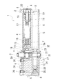
- the door closer in this embodiment includes a door closer body 1 as shown in FIGS. 1 and 2 show the door when it is fully closed, and FIGS. 3 and 4 show the door when it is fully open. Incidentally, FIGS. 5 to 9 to be described later all show the fully closed state.
- the door closer main body 1 includes a main body housing 2 and a main shaft 3 that is pivotally supported by the main body housing 2 and rotates about an axis in the vertical direction.
- a base end portion of an arm (not shown) is attached to the main shaft 3 so as not to be relatively rotatable.
- the door closer body 1 is attached to a door that rotates about an axis in the vertical direction or is attached to a door frame.
- a rail (not shown) that extends in the horizontal direction is attached to the door frame.
- the tip of the arm engages with the rail.
- the main body housing 2 as a whole has a horizontally long rectangular parallelepiped shape that is long in the horizontal direction (lateral direction), but has a shape that is longer in the vertical direction (longitudinal direction) than in the front-rear direction (depth direction in the drawing). Yes.
- the right side is the one end side in the horizontal direction and the left side is the other end side in the horizontal direction.
- the pivot center of the door is located on the left side with respect to the door closer body 1.
- the main housing 2 has two upper and lower chambers extending in the lateral direction.
- the upper chamber 4 and the lower chamber 5 are formed side by side with each other, and their axial directions are horizontal and parallel to each other, and each chamber is filled with hydraulic oil.
- the upper chamber 4 and the lower chamber 5 are separated from each other by a partition wall 6 located between them, and are independent chambers.
- the partition wall 6 has a through hole 7 formed therein, and the communication hole 7 Thus, the upper chamber 4 and the lower chamber 5 communicate with each other.
- the lower chamber 5 has a length close to the entire length of the main body housing 2 in the lateral direction, while the upper chamber 4 is shorter than the lower chamber 5.
- the lower chamber 5 is formed by forming a through-hole penetrating in the lateral direction in the main body housing 2 and closing both end openings of the through-hole with the lateral caps 8 respectively.
- the upper chamber 4 is formed on the right side with respect to the lower chamber 5. That is, the upper chamber 4 is formed by forming a non-penetrating lateral hole in the main body housing 2 that opens only on the right end and closing the right end opening with the lateral cap 8.
- a main spring that generates a closing force for closing the door is accommodated in the upper chamber 4, and a buffer piston 10 is provided in the lower chamber 5 to push hydraulic oil through the flow rate control flow path 9 in order to buffer the closing operation. Is housed.
- the main shaft 3 is disposed so as to penetrate through the upper chamber 4 and the lower chamber 5 together.
- the main shaft 3 is arranged on the left side of the lateral center of the main body housing 2 and is located near the left end of the upper chamber 4. That is, the main shaft 3 is arranged offset to the rotation center side of the door. Therefore, the main shaft 3 is located on the right side of the door closer body 1 from the main shaft 3 with respect to the dimension from the main shaft 3 to the left end portion of the door closer body 1. The dimension to the end is longer.
- the main shaft 3 is rotatably supported by the upper cap 11 and the lower cap 27 attached to the upper surface and the lower surface of the main body housing 2 via bearings, and is also rotatably supported by the partition wall 6 via the bearings. Yes.
- the upper end portion of the main shaft 3 protrudes upward by a predetermined length from the upper cap 11, and a base end portion of the arm (not shown) is formed on the upper protrusion portion of the main shaft 3. Is mounted in a relatively non-rotatable manner.
- a heart-shaped cam 12 is provided on the upper part of the main shaft 3.
- the cam 12 is not formed as a separate member from the main shaft 3 but is integrally formed so as to form one member with the main shaft 3.
- the cam 12 is located at a height corresponding to the upper chamber 4 and compresses the main spring during the opening operation, and receives a closing force due to its elastic restoring force from the main spring during the closing operation.
- the cam 12 is a plate cam whose circumferential surface is a cam surface, and is a section in which only a predetermined angle region of the entire circumference is used in the opening and closing operation of the door, from the recess 12a to the top 12b. One angle area is the use section 12c.
- the roller 12 as a cam follower supported by the vertical support shaft 13 is in contact with the cam 12.
- the support shaft 13 of the roller 14 is attached to a spring support 15 that can move in the upper chamber 4 along the lateral direction that is the axial direction of the upper chamber 4, and the spring support 15 is located on the right side of the main spring. Is pressed and compressed during the opening operation.
- the spring support 15 is formed with a through hole penetrating in the lateral direction, and hydraulic oil can pass through the through hole.
- the main spring consists of two large and small coil springs 16 and 17.
- the large diameter coil spring 16 and the small diameter coil spring 17 are arranged coaxially with each other. That is, the small-diameter coil spring 17 is inserted inside the large-diameter coil spring 16.
- an adjustment shaft 18 penetrates in the lateral direction at the center of the horizontal cap 8 of the upper chamber 4 and protrudes into the upper chamber 4 by a predetermined length, and a male screw portion is formed at the protruding portion.
- a spring force adjusting nut 19 is screwed into the male thread portion of the adjusting shaft 18.
- the adjustment shaft 18 is supported by the horizontal cap 8 so as to be rotatable about its axis, and an adjustment gear 20 is provided at the right end (outer end) of the adjustment shaft 18 slightly protruding outside the main body housing 2. It is attached. By rotating the adjusting gear 20 with an adjusting tool (not shown), the adjusting shaft 18 can be rotated to move the spring force adjusting nut 19 in the lateral direction.
- a large-diameter coil spring 16 is interposed between the spring force adjusting nut 19 and the spring support 15, and therefore the spring force can be adjusted.
- the small-diameter coil spring 17 is interposed between the spring support 15 and the left end portion (inner end portion) of the adjustment shaft 18, and therefore the spring force cannot be adjusted.
- the cam 12 rotates clockwise in FIG.
- the cam 12 has an angle exceeding 180 degrees clockwise from the recess 12a to the top 12b, for example, an angle of about 225 degrees, and even when the door is opened at a maximum of 180 degrees as shown in FIG. 14 does not reach the top 12 b of the cam 12.
- the cam 12 has an asymmetric shape in which the use section 12c used in the door opening / closing operation is longer than the unused section, which is the remaining circumference, of the entire circumference.
- a pinion gear 21 is formed integrally with the lower portion of the main shaft 3.
- the pinion gear 21 is not formed as a separate member from the main shaft 3 but is integrally formed so as to form one member with the main shaft 3.
- the pinion gear 21 is located below the cam 12 by a predetermined height and is positioned at a height corresponding to the lower chamber 5, and is used for buffering to move the buffer piston 10 in the lateral direction in accordance with the opening / closing operation of the door.
- the drive part is comprised.
- the buffer piston 10 has head portions 22 and 23 that slide on the wall surfaces of the lower chamber 5 at both ends thereof.
- a rack 24 is formed between the head portions 22 and 23, and the rack 24 has the main shaft 3.
- the pinion gear 21 is screwed.
- a through hole is formed in each of the head portions 22 and 23 in the center portion, and a check valve 25 is provided in the through hole of the left head portion 22.
- the buffer piston 10 moves to the right side.
- the ball that is the valve body of the check valve 25 moves to the left side to open the valve, and the hydraulic oil can be inserted through the through hole.
- the ball of the check valve 25 is pushed to the right side by hydraulic pressure to close the through hole, and the hydraulic oil cannot be inserted through the through hole.
- the hydraulic oil pushed to the left side by the buffer piston 10 during the closing operation is pushed into the flow rate control flow path 9 which is a bypass, and moves through the flow rate control flow path 9 to a region on the right side of the left head portion 22.
- the flow control channel 9 is provided with an adjustment valve 26 for controlling the flow rate of hydraulic oil flowing through the flow control channel 9.
- a plurality of the regulating valves 26, specifically three are arranged.
- the plurality of adjustment valves 26 are all disposed on the upper surface of the body housing 2. And can be adjusted from above. Since the buffer piston 10 is disposed in the lower chamber 5, the flow rate control channel 9 is formed from the wall surface of the lower chamber 5 to the vicinity of the upper surface of the main body housing 2. The upper chamber 4 is not formed on the left side of the cam 12 in the main body housing 2. A flow rate control flow path 9 is formed in a left portion of the upper portion of the main body housing 2 where the upper chamber 4 is not formed. That is, the main spring is disposed on the right side with the main shaft 3 as the center, and the flow rate control flow path 9 is formed on the left side opposite to the main spring.
- the door closer when the door closer according to the present embodiment is used, the door can be opened up to a maximum of 180 degrees, and the fully opened state opened 180 degrees is shown in FIGS.
- the buffer piston 10 When the door is fully open, the buffer piston 10 is moved to the right as much as possible. In this state, the buffer piston 10 is not in contact with the lateral cap 8 on the right side of the lower chamber 5 and the two are separated. That is, the lower chamber 5 is formed longer with a predetermined length margin on the right side (opening side) than the position where the buffer piston 10 has moved to the right side, which is the opening side, to the maximum. That is, in FIG. 3 and FIG. 4, the portion between the buffer piston 10 and the right lateral cap 8 is an extension 5 a of the lower chamber 5. The length of the extension 5a is longer than the stroke of the buffer piston 10 and is several times as long.
- the main shaft 3 rotates with the opening and closing operation of the door, and the spring support 15 and the buffer piston 10 move together by the rotation.
- the movement amount of the buffer piston 10 is larger. 3 and 4, when the spring support 15 and the buffer piston 10 are moved to the right as much as possible, the right end surface of the spring support 15 and the right end surface of the buffer piston 10 are laterally extended. It is in almost the same position. And the said communication hole 7 is formed in the right side rather than the position so that it may not be obstruct
- the main shaft 3 has a vertically divided structure in which two upper and lower shaft portions are connected and integrated in the vertical direction. That is, the main shaft 3 includes an upper shaft portion 30 and a lower shaft portion 31, and a lower end portion of the upper shaft portion 30 and an upper end portion of the lower shaft portion 31 are connected to each other so as not to be relatively rotatable. There are various connection structures, but in the present embodiment, the connection structures are connected by serrations 32 in the vertical direction.
- the cam 12 is integrally formed on the upper shaft portion 30, and the pinion gear 21 is integrally formed on the lower shaft portion 31.
- the upper shaft portion 30 is inserted from the upper surface of the main body housing 2, and the lower shaft portion 31 is inserted from the lower surface of the main body housing 2, and is connected to each other by a serration 32 at the position of the partition wall 6.
- the main shaft 3 is divided into the upper and lower parts, so that the cam 12 and the pinion gear 21 are not formed separately from the main shaft 3 but formed as a single member with high accuracy. Easy to do.
- the upper side shaft part 30 and the lower side shaft part 31 can be inserted from the upper surface and the lower surface of the main body housing 2, respectively, it can be assembled easily.
- the door closer configured as described above, since the main spring is compressed by the cam 12, the door can be easily opened to a fully open state of, for example, 180 degrees with a relatively light force after the door is opened at a predetermined angle. Further, immediately before the door is fully closed, the cam 12 can generate a large torque in the closing direction of the main shaft 3, so that the door can be reliably closed to the fully closed state. Therefore, it is suitable for use in a highly airtight room or the like, and is particularly effective for a slide type door closer.
- the main shaft 3 is formed with a pinion gear 21 as a buffer driving unit for moving the buffer piston 10, so that the buffer piston 10 can be easily moved without being restricted by the cam 12. Can be moved greatly. Accordingly, the buffer piston 10 can be moved greatly during the door closing operation so that a sufficient amount of hydraulic oil can be pushed into the flow rate control flow path 9, and the flow rate of the hydraulic oil can be easily adjusted by the adjustment valve 26.
- the cam 12 and the pinion gear 21 are arranged so as to be displaced in the vertical direction, the interference between the two can be easily prevented and the arrangement thereof is also easy. Moreover, the size of the door closer body 1 in the front-rear direction can be reduced in combination with the formation of the upper chamber 4 and the lower chamber 5 arranged in parallel in the vertical direction. Is suitable.
- the main spring and the buffer piston 10 are separately disposed in the upper chamber 4 and the lower chamber 5, interference between the operation of the main spring and the operation of the buffer piston 10 can be easily prevented, and the closing force can be reduced. It can be generated exactly as designed, and the hydraulic oil can be smoothly pushed into the flow rate control flow path 9. Further, since the main spring is disposed in the upper chamber 4, the mechanism for adjusting the spring force is located at the upper part of the main body housing 2 together with the adjusting valve 26, and both the spring force and the flow rate of the hydraulic oil are present. Adjustment can be easily performed from above, and adjustment work particularly in the conshield type is facilitated.
- the extension part 5a is formed on the right side of the lower chamber 5, the amount of hydraulic oil can be increased correspondingly, and deterioration of the hydraulic oil can be suppressed.
- the hydraulic oil since the upper chamber 4 and the lower chamber 5 communicate with each other through the communication hole 7, the hydraulic oil has a large capacity as a whole even if the chambers are arranged vertically one above the other. Compared to the configuration in which the chamber 4 and the lower chamber 5 do not communicate with each other, the hydraulic oil is stabilized and braking is also stabilized.
- air is mixed into the hydraulic oil in order to absorb and mitigate expansion of the hydraulic oil due to temperature rise.
- the air accumulates in the upper chamber 4, but since the main spring is disposed in the upper chamber 4 and the buffer piston 10 is disposed in the lower chamber 5, it is difficult for the air to enter the flow control flow path 9. , Abnormal noise generated when air passes through the flow rate control flow path 9 can be suppressed.
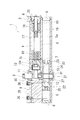
- the main spring is disposed in the upper chamber 4 and the buffer piston 10 is disposed in the lower chamber 5, but the opposite arrangement may be employed. That is, as shown in FIG. 5, the buffer piston 10 is arranged in the upper chamber 4, and the main spring (large-diameter coil spring 16 and small-diameter coil spring 17) is arranged in the lower chamber 5, and the pinion gear 21 is formed on the upper shaft portion 30.
- the cam 12 may be formed on the lower shaft portion 31.
- the lower cap 27 is not provided. Therefore, the upper shaft portion 30 and the lower shaft portion 31 are inserted from the upper surface of the main body housing 2. In this embodiment, the upper shaft portion 30 and the lower shaft portion 31 are connected to each other using a square shaft portion 33.
- an extension 4a is provided on the right side of the upper chamber 4 in the same manner as the extension 5a of the lower chamber 5 in FIG.
- the lower chamber 5 is also provided with an extension 5a on the left side. That is, since the extension 5a is formed in the lower chamber 5 on the left side opposite to the side on which the main spring is disposed with respect to the cam 12, the upper chamber 4 and the lower chamber 5 are arranged in the lateral direction. Are almost equal in length.
- both the upper chamber 4 and the lower chamber 5 are provided with the extension portions 4a and 5a, the hydraulic oil can be filled in a larger amount, which is more effective in preventing the hydraulic oil from being deteriorated.
- the buffer piston 10 is disposed in the upper chamber 4, the flow rate control flow path 9 formed so as to extend upward from the upper chamber 4 is shorter than in the case of FIG. 1.
- the auxiliary spring 40 in the right side of the buffer piston 10 like FIG. That is, the spring support 41 is disposed on the extension 4 a of the upper chamber 4, and the auxiliary spring 40 is disposed between the spring support 41 and the right lateral cap 8.
- the spring support 41 has a larger diameter (larger) than the right-side head portion 23 of the buffer piston 10, and the wall surface of the upper chamber 4 has a larger diameter by a predetermined length, and a spring is supported on the larger diameter portion of the predetermined length.
- the body 41 is slidably arranged.
- FIG. 6 shows a state in which the door is in the fully closed state.
- the spring support 41 In the fully closed state, the spring support 41 is pushed by the auxiliary spring 40 and is at the leftmost side, that is, a position close to the buffer piston 10.
- the spring support 41 is in contact with the stepped portion of the wall surface of the upper chamber 4 and cannot move further to the left, is not in contact with the buffer piston 10, and is separated from the buffer piston 10 to the right by a predetermined distance. It is in.
- the buffer piston 10 contacts the spring support 41, and the buffer piston 10 pushes and compresses the auxiliary spring 40 via the spring support 41 at a door opening angle larger than that.
- the auxiliary spring 40 starts compressive deformation from the initial state (normal state) only when the door is opened by a predetermined angle or more, and at the opening angle less than the predetermined angle, it is not pushed by the buffer piston 10 and is compressed in the initial state. Does not deform.
- the initial state of the auxiliary spring 40 may be a natural length, but is preferably compressed by a predetermined amount.
- the door opening angle at the start of compression may be set arbitrarily, but can be set to 100 degrees, for example.
- the configuration using the cam 12 has an advantage that the door can be opened easily with a light force because the force required to gradually open immediately after the start of the door opening operation is reduced.
- auxiliary spring 40 can be similarly applied to the configuration shown in FIG.
- an auxiliary spring 40 may be provided on the extension 5 a of the lower chamber 5.
- an extension portion may be provided in the chamber in which the buffer piston 10 is arranged, and the auxiliary spring 40 may be arranged in the extension portion.
- the buffer piston 10 may be arranged in the opposite direction to that described above.
- the buffer piston 10 moves to the left side during the door opening operation and moves to the right side during the door closing operation.
- the check valve 25 is provided in the right head portion 23.
- the right head portion 23 includes a main portion 50 and an extending portion 51 connected and integrated on the right side of the main portion 50, and the right end portion of the extending portion 51. Is provided with a check valve 25.
- a flow rate control channel 9 is also provided on the right side of the main body housing 2.
- the size of the door closer body 1 on the left side can be shortened.
- the main shaft 3 can be brought close to the rotation center of the door.
- the main shaft 3 can be positioned at the rotation center of the door, and a configuration in which the rotation center axis of the door itself is the main shaft 3 is also possible.
- an extension 5 a is provided on the left side of the lower chamber 5.
- the cam 12 and the pinion gear 21 are each integrally formed on the main shaft 3.
- the cam 12 and the pinion gear 21 may be separated from the main shaft 3 and assembled to the main shaft 3. .
- the pinion gear 21 is formed on the main shaft 3 and the rack 24 is formed on the buffer piston 10.
- the buffer drive unit for moving the buffer piston 10 according to the door opening / closing operation is as described above.
- Various mechanisms can be employed without being limited to the rack and pinion mechanism.
- a screw portion is formed on the buffer piston 10 and screwed with the screw portion of the main shaft 3, and this screw feed mechanism is used as a buffer driving portion. With this rotation, the buffer piston 10 may be moved along the axial direction of the main shaft 3.
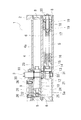
- a main body housing 2 is formed with a horizontally long upper chamber 4 extending laterally from the main shaft 3 and a vertically long lower chamber 5 extending downward along the axial direction of the main shaft 3.
- a cam 12 is formed on the upper portion of the main shaft 3
- a large-diameter coil spring 16 and a small-diameter coil spring 17 are disposed in the upper chamber 4 corresponding to the position, and a buffer piston 10 is disposed in the lower chamber 5.
- the lower shaft portion 31 connected in the axial direction via the upper shaft portion 30 and the serration 32 includes a shaft main portion 60 having a serration 32, and an upper end portion fixed to the shaft main portion 60. And a cylindrical rotating cylinder 61 extending in the direction.
- a female screw portion 61a is formed on the inner peripheral surface of the rotary cylinder 61, and a male screw portion 10a in a predetermined region on the outer peripheral surface of the buffer piston 10 is screwed to the female screw portion 61a.
- the buffer piston 10 moves up and down inside the rotating cylinder 61.
- a check valve 25 is provided at an upper portion of the buffer piston 10, and the buffer piston 10 is lowered during the door opening operation and is raised during the door closing operation to push the hydraulic oil into the flow rate control passage 9.
- An adjustment rod 62 passes through the center of the upper portion of the buffer piston 10 upward.
- the adjusting rod 62 is independent of the main shaft 3, and therefore does not rotate with the rotation of the main shaft 3.
- the adjustment rod 62 is screwed into the lower cap 27 and its lower end protrudes downward from the main body housing 2, and an adjustment gear 63 is fixed thereto.
- the adjustment rod 62 is rotated by engaging a tool (not shown) with the adjustment gear 63 to change the screwing amount with respect to the lower cap 27, so that the adjustment rod 62 can move up and down.
- the upper predetermined region of the adjustment rod 62 has a tapered shape that gradually decreases in diameter toward the lower side, and the tapered portion 62a is inserted through the through hole in the upper portion of the buffer piston 10.
- a slight gap is formed between the upper through hole of the buffer piston 10 and the adjustment rod 62.
- the adjustment rod 62 When the adjustment rod 62 is raised, the gap becomes wider, and conversely, it becomes narrower.
- This gap constitutes the flow control flow path 9, the adjustment rod 62 functions as an adjustment valve, and when the buffer piston 10 is raised during the door closing operation, the hydraulic oil passes through the gap between the upper through hole and the adjustment rod 62. To move down.
- the main housing 2 is provided with two chambers, the main spring is disposed in one chamber, and the buffer piston 10 is disposed in the other chamber, whereby the compression operation of the main spring and the movement operation of the buffer piston 10 are performed. It is possible to easily prevent mutual interference.
- the cam 12 does not have to have the asymmetric shape as described above. As shown in FIG. 9, the cam 12 has a symmetrical shape in which the used section 12c used in the opening / closing operation and the unused section not used have the same peripheral length. Also good. In FIG. 9, the concave portion 12a, the center of the cam 12, and the top portion 12b are in a straight line.
- a so-called interior stop device in which a stop mechanism for holding the door in a predetermined opening angle state is provided in the rack 24 may be provided.
- the door closer body 1 is disposed on the door and the main shaft 3 is fixed to the door frame so as not to be relatively rotatable. Conversely, the door closer body 1 is disposed on the door frame and the main shaft 3 is not relatively rotatable on the door. Depending on whether it is fixed, the main shaft 3 may be used as the center of rotation of the door.
Landscapes
- Closing And Opening Devices For Wings, And Checks For Wings (AREA)
Description
ができるという利点がある反面、逆に、全開状態から閉扉動作が開始される際にはメインバネからカム12に伝わる閉じ力が弱いという欠点もある。従って、上述のように補助バネ40を配置することにより、特に全開状態から閉じ始めの閉じ力を補助バネ40で補うことができ、確実に閉扉動作が開始されることになる。かかる補助バネ40は、図1に示した構成にも同様に適用できる。図1の場合には緩衝ピストン10が下部室5に配置されているので、その下部室5の延長部5aに補助バネ40を設けるようにすればよい。何れにしても、緩衝ピストン10が配置された室に延長部を設けてその延長部に補助バネ40を配置するようにすればよい。
2 本体ハウジング
3 主軸
4 上部室
4a 延長部
5 下部室
5a 延長部
6 隔壁
7 連通孔
8 横キャップ
9 流量制御流路
10 緩衝ピストン
10a 雄ネジ部
11 上キャップ
12 カム
12a 凹部
12b 頂部
12c 使用区間
13 支軸
14 コロ
15 バネ支持体
16 大径のコイルバネ(メインバネ)
17 小径のコイルバネ(メインバネ)
18 調整軸
19 バネ力調整ナット
20 調整ギア
21 ピニオンギア(緩衝用駆動部)
22 ヘッド部
23 ヘッド部
24 ラック
25 逆止弁
26 調整弁
27 下キャップ
30 上側軸部
31 下側軸部
32 セレーション
33 角軸部
40 補助バネ
41 バネ支持体
50 主部
51 延在部
60 軸主部
61 回転筒体
61a 雌ネジ部(緩衝用駆動部)
62 調整ロッド
62a テーパ部
63 調整ギア
Claims (7)
- 扉の開閉動作に伴って回転する主軸と、閉じ力を発生させるためのメインバネと、閉扉動作を緩衝すべく作動油を流量制御流路に押し流すための緩衝ピストンとを備え、
主軸には、開扉動作時にメインバネを弾性変形させ、閉扉動作時にメインバネの閉じ力を受けるカムが設けられると共に、扉の開閉動作に応じて緩衝ピストンを移動させるための緩衝用駆動部が前記カムとは別に設けられていることを特徴とするドアクローザ。 - 主軸と一体に回転するアームの先端部がレールに案内されてスライドするように構成されたスライド型のドアクローザである請求項1記載のドアクローザ。
- 本体ハウジングに二つの室が設けられ、一方の室にメインバネが配置され、他方の室に緩衝ピストンが配置されている請求項1又は2記載のドアクローザ。
- 主軸の軸線方向が上下方向であって緩衝用駆動部はカムに対して上下に位置ずれして設けられており、本体ハウジングには作動油が入れられた上部室及び下部室が形成され、該上部室と下部室のうち、一方の室にメインバネが配置され、他方の室に緩衝ピストンが配置されている請求項3記載のドアクローザ。
- 緩衝用駆動部としてピニオンギアが設けられ、緩衝ピストンにはピニオンギアと螺合するラックが形成され、メインバネの弾性変形方向と緩衝ピストンの移動方向とが互いに平行であって上部室と下部室とが上下に並んで配置され、
カムに対してメインバネが配置されている側とは反対側と、緩衝ピストンが開扉側に最大限移動した箇所よりも更にその開扉側のうち、少なくとも一方には室の延長部が形成されている請求項4記載のドアクローザ。 - 緩衝ピストンが開扉側に最大限移動した箇所よりも更にその開扉側に室の延長部が形成され、該延長部には、所定角度未満の扉の開き角度では弾性変形せず所定角度以上の扉の開き角度で弾性変形する補助バネが設けられている請求項5記載のドアクローザ。
- 主軸が上下分割構成とされ、主軸を構成する上側軸部と下側軸部のうち、一方にカムが一体的に形成され、他方に緩衝用駆動部としてピニオンギアが一体的に形成され、緩衝ピストンにはピニオンギアと螺合するラックが形成されている請求項4記載のドアクローザ。
Priority Applications (4)
| Application Number | Priority Date | Filing Date | Title |
|---|---|---|---|
| AU2013321794A AU2013321794B2 (en) | 2012-09-28 | 2013-05-21 | Door closer |
| US14/430,849 US20150218867A1 (en) | 2012-09-28 | 2013-05-21 | Door closer |
| CN201380049957.9A CN104662246B (zh) | 2012-09-28 | 2013-05-21 | 闭门器 |
| EP13840928.9A EP2902576A4 (en) | 2012-09-28 | 2013-05-21 | DOOR LOCK |
Applications Claiming Priority (2)
| Application Number | Priority Date | Filing Date | Title |
|---|---|---|---|
| JP2012-218351 | 2012-09-28 | ||
| JP2012218351A JP5952154B2 (ja) | 2012-09-28 | 2012-09-28 | ドアクローザ |
Publications (1)
| Publication Number | Publication Date |
|---|---|
| WO2014050204A1 true WO2014050204A1 (ja) | 2014-04-03 |
Family
ID=50387623
Family Applications (1)
| Application Number | Title | Priority Date | Filing Date |
|---|---|---|---|
| PCT/JP2013/064037 Ceased WO2014050204A1 (ja) | 2012-09-28 | 2013-05-21 | ドアクローザ |
Country Status (6)
| Country | Link |
|---|---|
| US (1) | US20150218867A1 (ja) |
| EP (1) | EP2902576A4 (ja) |
| JP (1) | JP5952154B2 (ja) |
| CN (1) | CN104662246B (ja) |
| AU (1) | AU2013321794B2 (ja) |
| WO (1) | WO2014050204A1 (ja) |
Families Citing this family (9)
| Publication number | Priority date | Publication date | Assignee | Title |
|---|---|---|---|---|
| JP6343531B2 (ja) * | 2014-09-16 | 2018-06-13 | 日本ドアーチエック製造株式会社 | ドアクローザ |
| PL3109389T3 (pl) * | 2015-06-26 | 2018-03-30 | Locinox | Urządzenie do zamykania zawiasowego elementu |
| JP7177003B2 (ja) * | 2019-05-28 | 2022-11-22 | リョービ株式会社 | ドアクローザ |
| JP7370846B2 (ja) * | 2019-12-18 | 2023-10-30 | リョービ株式会社 | ドアクローザ |
| CN113356713B (zh) * | 2020-03-02 | 2024-07-26 | 丽水市神飞利益保安用品有限公司 | 一种双向致动的液压闭合器 |
| CN113622776B (zh) * | 2021-07-28 | 2024-09-03 | 箭牌家居集团股份有限公司 | 一种闭门器 |
| JP7768794B2 (ja) * | 2022-02-10 | 2025-11-12 | リョービ株式会社 | ドアクローザ |
| JP7737920B2 (ja) * | 2022-02-10 | 2025-09-11 | リョービ株式会社 | ドアクローザ |
| CN221546713U (zh) * | 2023-12-11 | 2024-08-16 | 东莞力督门控设备有限公司 | 窄边框门用凸轮液压闭门器 |
Citations (7)
| Publication number | Priority date | Publication date | Assignee | Title |
|---|---|---|---|---|
| GB396889A (en) * | 1932-05-11 | 1933-08-17 | James Garth Mitchell | Improvements relating to hinges |
| JPH0520547B2 (ja) | 1983-12-13 | 1993-03-19 | Doruma Gmbh Unto Co Kg | |
| JPH10196213A (ja) * | 1997-01-14 | 1998-07-28 | Nippon Door Check Mfg Corp | 扉自動閉塞装置 |
| JP2003035065A (ja) * | 2001-05-11 | 2003-02-07 | Ryobi Ltd | ドアクローザ |
| JP2004143812A (ja) * | 2002-10-24 | 2004-05-20 | Nhk Spring Co Ltd | ドア開放補助装置 |
| JP2006176984A (ja) * | 2004-12-21 | 2006-07-06 | Ryobi Ltd | ドアクローザ |
| JP2006200352A (ja) * | 2004-12-21 | 2006-08-03 | Nhk Spring Co Ltd | ドアクローザ |
Family Cites Families (14)
| Publication number | Priority date | Publication date | Assignee | Title |
|---|---|---|---|---|
| US1097605A (en) * | 1914-01-21 | 1914-05-19 | Henry G Voight | Door-closer. |
| US2003669A (en) * | 1932-02-04 | 1935-06-04 | Yale & Towne Mfg Co | Door closer |
| CN2148153Y (zh) * | 1992-07-21 | 1993-12-01 | 青田县兴华总厂 | 自动闭门器 |
| DE102004012637B4 (de) * | 2004-03-12 | 2008-10-16 | Dorma Gmbh + Co. Kg | Türschließer |
| CN101084361A (zh) * | 2004-12-21 | 2007-12-05 | 日本发条株式会社 | 闭门器 |
| FR2894610B1 (fr) * | 2005-12-12 | 2019-03-22 | Sa Lavasseur Systemes | Dispositif d'ouverture et de fermeture d'un vantail de porte de type va-et-vient |
| JP4904078B2 (ja) * | 2006-04-27 | 2012-03-28 | Dtエンジニアリング株式会社 | ドアクローザー |
| US20080034535A1 (en) * | 2006-07-20 | 2008-02-14 | Chi-Tsao Chiang | Door closer |
| CN101135220B (zh) * | 2006-09-01 | 2012-12-12 | 多玛两合有限公司 | 闭门器特别是用于隐蔽地安装于门扇或门扇的成型门框中的内部闭门器 |
| CN201095926Y (zh) * | 2007-08-29 | 2008-08-06 | 东莞力督门控设备有限公司 | 闭门器 |
| CN201372656Y (zh) * | 2009-02-24 | 2009-12-30 | 肇庆市志成气动有限公司 | 一种带安全阀的闭门器液压机构 |
| CN201416336Y (zh) * | 2009-04-24 | 2010-03-03 | 东莞市坚朗五金制品有限公司 | 滑轨式摇臂 |
| DE102013100293A1 (de) * | 2013-01-11 | 2014-07-17 | Eco Schulte Gmbh & Co. Kg | Türschließerantrieb |
| US8863357B1 (en) * | 2013-05-08 | 2014-10-21 | Heng Kuo Co., Ltd | Adjustable door closer |
-
2012
- 2012-09-28 JP JP2012218351A patent/JP5952154B2/ja active Active
-
2013
- 2013-05-21 WO PCT/JP2013/064037 patent/WO2014050204A1/ja not_active Ceased
- 2013-05-21 US US14/430,849 patent/US20150218867A1/en not_active Abandoned
- 2013-05-21 CN CN201380049957.9A patent/CN104662246B/zh active Active
- 2013-05-21 EP EP13840928.9A patent/EP2902576A4/en not_active Withdrawn
- 2013-05-21 AU AU2013321794A patent/AU2013321794B2/en active Active
Patent Citations (7)
| Publication number | Priority date | Publication date | Assignee | Title |
|---|---|---|---|---|
| GB396889A (en) * | 1932-05-11 | 1933-08-17 | James Garth Mitchell | Improvements relating to hinges |
| JPH0520547B2 (ja) | 1983-12-13 | 1993-03-19 | Doruma Gmbh Unto Co Kg | |
| JPH10196213A (ja) * | 1997-01-14 | 1998-07-28 | Nippon Door Check Mfg Corp | 扉自動閉塞装置 |
| JP2003035065A (ja) * | 2001-05-11 | 2003-02-07 | Ryobi Ltd | ドアクローザ |
| JP2004143812A (ja) * | 2002-10-24 | 2004-05-20 | Nhk Spring Co Ltd | ドア開放補助装置 |
| JP2006176984A (ja) * | 2004-12-21 | 2006-07-06 | Ryobi Ltd | ドアクローザ |
| JP2006200352A (ja) * | 2004-12-21 | 2006-08-03 | Nhk Spring Co Ltd | ドアクローザ |
Non-Patent Citations (1)
| Title |
|---|
| See also references of EP2902576A4 |
Also Published As
| Publication number | Publication date |
|---|---|
| JP5952154B2 (ja) | 2016-07-13 |
| EP2902576A1 (en) | 2015-08-05 |
| US20150218867A1 (en) | 2015-08-06 |
| CN104662246B (zh) | 2016-09-28 |
| EP2902576A4 (en) | 2015-10-21 |
| JP2014070442A (ja) | 2014-04-21 |
| CN104662246A (zh) | 2015-05-27 |
| AU2013321794A1 (en) | 2015-04-09 |
| AU2013321794B2 (en) | 2015-07-09 |
Similar Documents
| Publication | Publication Date | Title |
|---|---|---|
| JP5952154B2 (ja) | ドアクローザ | |
| JP4651684B2 (ja) | 両開用自動閉扉蝶番及び両開扉構造 | |
| US20090277734A1 (en) | Methods and apparatus for position sensitive suspension dampening | |
| WO2020016916A1 (ja) | 油圧緩衝器 | |
| CN101641486A (zh) | 关门器 | |
| EP2966250A1 (en) | Door closer | |
| JP6006150B2 (ja) | ドアクローザ | |
| JP6159448B2 (ja) | ドアクローザ | |
| TWI529294B (zh) | Door closet | |
| CN110273967A (zh) | 旋转阻尼铰链 | |
| JP6178083B2 (ja) | ドアクローザ | |
| JP5940033B2 (ja) | ドアクローザ | |
| JP6711712B2 (ja) | ドアクローザ用速度調整弁 | |
| JP5073372B2 (ja) | ドアクローザ | |
| JP2012066644A (ja) | ペダル装置 | |
| JP4056455B2 (ja) | 縦軸型ドアークローザー | |
| WO2015071963A1 (ja) | ドアクローザ | |
| JP4911496B2 (ja) | 原稿圧着板の開閉装置 | |
| JP7480028B2 (ja) | ドアクローザ | |
| JP7177003B2 (ja) | ドアクローザ | |
| JP2025071942A (ja) | ドアクローザ | |
| JP5939854B2 (ja) | ドアクローザ | |
| JP2025026301A (ja) | ドアクローザ | |
| JP4642058B2 (ja) | 縦軸型ドアークローザー | |
| JP2023117056A (ja) | ドアクローザ |
Legal Events
| Date | Code | Title | Description |
|---|---|---|---|
| 121 | Ep: the epo has been informed by wipo that ep was designated in this application |
Ref document number: 13840928 Country of ref document: EP Kind code of ref document: A1 |
|
| WWE | Wipo information: entry into national phase |
Ref document number: 14430849 Country of ref document: US |
|
| WWE | Wipo information: entry into national phase |
Ref document number: 2013840928 Country of ref document: EP |
|
| NENP | Non-entry into the national phase |
Ref country code: DE |
|
| ENP | Entry into the national phase |
Ref document number: 2013321794 Country of ref document: AU Date of ref document: 20130521 Kind code of ref document: A |