WO2014058009A1 - Dispositif de conditionnement d'air pour véhicule - Google Patents
Dispositif de conditionnement d'air pour véhicule Download PDFInfo
- Publication number
- WO2014058009A1 WO2014058009A1 PCT/JP2013/077584 JP2013077584W WO2014058009A1 WO 2014058009 A1 WO2014058009 A1 WO 2014058009A1 JP 2013077584 W JP2013077584 W JP 2013077584W WO 2014058009 A1 WO2014058009 A1 WO 2014058009A1
- Authority
- WO
- WIPO (PCT)
- Prior art keywords
- passage
- air
- mix
- blowing
- guide
- Prior art date
- Legal status (The legal status is an assumption and is not a legal conclusion. Google has not performed a legal analysis and makes no representation as to the accuracy of the status listed.)
- Ceased
Links
Images


Classifications
-
- B—PERFORMING OPERATIONS; TRANSPORTING
- B60—VEHICLES IN GENERAL
- B60H—ARRANGEMENTS OF HEATING, COOLING, VENTILATING OR OTHER AIR-TREATING DEVICES SPECIALLY ADAPTED FOR PASSENGER OR GOODS SPACES OF VEHICLES
- B60H1/00—Heating, cooling or ventilating devices
- B60H1/00642—Control systems or circuits; Control members or indication devices for heating, cooling or ventilating devices
- B60H1/00664—Construction or arrangement of damper doors
- B60H1/00671—Damper doors moved by rotation; Grilles
- B60H1/00685—Damper doors moved by rotation; Grilles the door being a rotating disc or cylinder or part thereof
-
- B—PERFORMING OPERATIONS; TRANSPORTING
- B60—VEHICLES IN GENERAL
- B60H—ARRANGEMENTS OF HEATING, COOLING, VENTILATING OR OTHER AIR-TREATING DEVICES SPECIALLY ADAPTED FOR PASSENGER OR GOODS SPACES OF VEHICLES
- B60H1/00—Heating, cooling or ventilating devices
- B60H1/00642—Control systems or circuits; Control members or indication devices for heating, cooling or ventilating devices
- B60H1/00664—Construction or arrangement of damper doors
- B60H2001/00721—Air deflecting or air directing means
Definitions
- This invention relates to a vehicle air conditioner equipped with a rotary type mix door.
- a general vehicle air conditioner accommodates a cooling heat exchanger (evaporator) or a heating heat exchanger (heater core) in an air flow path in a case, and cools the air introduced into the case as a cooling heat exchanger. A part of this cooled air is reheated with a heat exchanger for heating, and then the reheated air is mixed with the air that bypasses the heat exchanger for heating, and the blowout provided on the most downstream side The vehicle is supplied from the opening to the passenger compartment.
- a cooling heat exchanger evaporator
- a heating heat exchanger herein
- the blowout opening is a defrost blowout opening that supplies temperature-controlled air toward the window glass, an upper blowout opening that mainly supplies temperature-controlled air toward the upper body of the occupant, and a temperature toward the feet of the occupant. And a lower outlet opening including a foot outlet opening for supplying conditioned air.
- the cool air passage through which the air bypassing the heating heat exchanger flows is formed near the upper blowing opening, and the hot air passage through which the air passing through the heating heat exchanger flows is formed near the lower blowing opening. .
- Patent Document 1 A configuration in which a guide passage is provided has been proposed.
- the air distribution adjusting damper used here is composed of a rotary damper.
- the rotary damper is composed of a shaft portion, a shielding portion provided on the downstream side of the shaft portion, and the outside of the opening end of the shielding portion on the evaporator side.
- a guide passage provided so as to protrude into the guide passage, and by flowing a part of the warm air through the guide passage, it is intended to guide to the vent opening side or the defrost opening side without mixing with the cold air It is.
- the air distribution door has a function of adjusting the temperature of the air supplied to the blowout opening. Therefore, the air distribution tuning and the temperature tuning must be performed by one air distribution adjustment damper. It becomes difficult to make both functions tuned at the same time.
- the shielding portion is provided on the downstream side from the shaft portion, and the guide passage is provided outside the opening end on the evaporator side. It is necessary to extend the guide plate. In the air conditioning case, it is necessary to secure a space for accommodating the air distribution adjusting damper in anticipation of the protrusion of the guide passage, and it becomes impossible to avoid an increase in the size of the air conditioning apparatus.
- the present invention has been made in view of such circumstances, and uses a guide passage provided in a mix door to reduce the temperature difference between air blown from an upper blowout opening and air blown from a lower blowout opening.
- the temperature control function can be integrated into the mix door to facilitate temperature tuning, and the mix door can be prevented from being enlarged, and by extension, the air conditioner can be prevented from being enlarged. This is the main issue.
- an air conditioner for a vehicle includes a case having an inlet for introducing air and a plurality of outlets for blowing out air, and the introduced air is introduced into the case.
- Heating heat exchanger for heating hot air passage through which air that has passed through the heating heat exchanger flows, bypass passage through which air that bypasses the heat exchanger for heating flows, and air that has flowed through the hot air passage
- a vehicle air conditioner comprising: a first outlet passage that leads to at least one of an opening and a vent outlet opening; and a second outlet passage that guides air from the mix space to the foot outlet opening.
- the hot air passage, the bypass passage, the first blowing passage, and the second blowing passage surround the rotation space around the mix space, and the hot air passage, the bypass passage,
- a blocking portion that is arranged in the order of the first blowing passage and the second blowing passage, the mix door is provided on the upstream side of the rotating shaft, and adjusts the opening degree of the warm air passage and the bypass passage with respect to the mix space.
- a guide passage configured as at least one of the passages leading to the second blowing passage side.
- the function of adjusting the opening ratio of the hot air passage and the bypass passage to the mix space by adjusting the opening ratio of the hot air passage and the bypass passage to the mix space, and one of the air flowing through the hot air passage by the guide passage.
- a function of adjusting the temperature of the air finally blown out from the blow-off opening by providing at least one of a passage that leads the portion to the first blow-off passage side and a passage that leads a part of the air flowing through the bypass passage to the second blow-off passage side Therefore, the temperature control function can be integrated into the mix door, and the temperature of the blown air can be easily tuned.
- the closed portion of the mix door is provided on the upstream side of the rotary shaft and the guide passage is provided between the rotary shaft and the closed portion, there is no need to provide a guide passage outside the open end of the mix door. Can be avoided. Since the guide passage is provided on the upstream side of the rotating shaft, a part of the warm air or the cold air flowing into the mix space can be taken into the guide passage effectively.
- the guide passage includes a first guide passage that guides a part of the air flowing through the warm air passage toward the first outlet passage, and a second guide that guides a part of the air flowing through the bypass passage toward the second outlet passage. It is good to have a passage.
- the temperature of the air directed to at least one of the defrost outlet opening and the vent outlet opening can be relatively increased, and the air flowing toward the foot outlet opening can be relatively increased. Since the temperature can be relatively lowered, it is possible to reduce the temperature difference between the air blown out from the blowout openings.
- a cooling heat exchanger may be further accommodated in the case.
- the reheated air is blown out in the bi-level mode or the differential foot mode, it is possible to effectively reduce the temperature difference of the air blown out from each blowing opening.
- the first guide passage and the second guide passage are alternately arranged in the axial direction of the rotating shaft. It is preferable. If the first guide passages and the second guide passages are alternately arranged in the axial direction of the rotating shaft in this way, the air guided to the first blowing passage side and the air guided to the second blowing passage side are respectively axial directions of the rotating shaft. No bias.
- the second guide passage is provided in an intermediate portion of the mix door in the axial direction of the rotary shaft, and the first guide passage is provided on both sides of the first guide passage in the axial direction of the rotary shaft. If it does so, it will be easy to flow the warm air guide
- the introduction part in the movable area of the mix door, the overhang of the introduction part can be suppressed in the movable area, and the size of the air conditioner can be avoided.
- the rotation axis of the mode door may be supported on the same axis as the rotation axis of the mix door.
- a rotary type mix door whose rotary shaft is rotatably supported by the case is disposed, and in this mix space, along the circumferential direction of the rotary shaft, A hot air passage through which air that has passed through the heat exchanger for heating flows, a bypass passage through which air that bypasses the heat exchanger for heating flows, and a first air that guides the air from the mix space to at least one of the defrost outlet opening and the vent outlet opening.
- the mix door is provided on the upstream side of the rotating shaft, and the hot air passage and the bypass passage And a guide passage formed between the rotary shaft and the closure portion, and a part of the air flowing through the warm air passage toward the first outlet passage. Because it is configured as at least one of the passages that lead a part of the air that flows through the bypass passage and bypass passage to the second blowout passage side, it is possible to consolidate the temperature control function in the mix door, and easy tuning of the blowout air temperature Can be done.
- the guide passage is provided on the upstream side of the rotation shaft, a part of the air flowing into the mix space can be taken into the guide passage effectively.
- the 1st guide passage which guides a part of air which flows through a warm air passage to the 1st blowing passage side
- the 2nd guide passage which leads a part of air which flows through a bypass passage to the 2nd blowing passage side
- the air temperature toward at least one of the defrost outlet opening and the vent outlet opening is relatively increased, and the air temperature toward the foot outlet opening is relatively increased. Therefore, it is possible to effectively reduce the temperature difference between the air blown out from the blowout openings.
- Such a configuration is an effective configuration even in a vehicle air conditioner that does not include a cooling heat exchanger, but also in a vehicle air conditioner that includes a cooling heat exchanger, the air blown out from each outlet opening.
- the temperature difference can be effectively reduced.
- the first blow-out passage is formed by alternately arranging the first guide passage and the second guide passage in the axial direction of the rotation shaft.
- the air led to the second air passage and the air led to the second blowing passage are not biased in the axial direction of the rotary shaft.
- the second guide passage is provided in an intermediate portion of the mix door in the axial direction of the rotary shaft, and the first guide passage is provided on both sides of the second guide passage in the axial direction of the rotary shaft. It is possible to flow the warm air guided to the first blowing passage side without being biased in any of the axial directions of the rotation shaft.
- the introduction part in the movable area of the mix door, the overhang of the introduction part can be suppressed in the movable area of the mix door, and the size of the air conditioner can be avoided.
- FIG. 1 is a diagram showing an example of the overall configuration of a vehicle air conditioner according to the present invention.
- FIG. 2 is a perspective view showing internal components by removing a part of the case of the vehicle air conditioner according to the present invention.
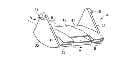
- FIG. 3 is a perspective view showing a mix door used in the vehicle air conditioner according to the present invention.
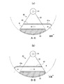
- FIG. 4 is a cross-sectional view for explaining the structure of the mix door.
- FIG. 4A is a cross-sectional view in the vicinity of both sides with respect to the axial direction of the rotation axis of the mix door (cross-sectional view cut along line AA in FIG. 3).
- FIG. 4A is a cross-sectional view in the vicinity of both sides with respect to the axial direction of the rotation axis of the mix door (cross-sectional view cut along line AA in FIG. 3).
- FIG. 5B is a cross-sectional view in the vicinity of the center with respect to the axial direction of the rotating shaft of the mix door (cross-sectional view cut along the line BB in FIG. 3).
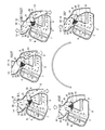
- FIG. 5 is a diagram for explaining the air flow in each blowing mode of the vehicle air conditioner according to the present invention.
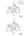
- FIG. 6 is a diagram for explaining the air flow in the bi-level mode or the differential foot mode, and (a) is a diagram for explaining the air flow in the section cut along the line AA in FIG.
- FIG. 4B is a diagram illustrating the air flow in a cross section cut along the line BB in FIG. 3.
- FIG. 1 shows an air conditioning unit 1 of a center-place type vehicle air conditioner mounted on a center console portion of a vehicle.
- the air conditioning unit 1 is arranged closer to the vehicle compartment side than the partition plate that partitions the engine room and the vehicle compartment.
- Outside air vehicle compartment outside air
- inside air vehicle compartment air
- blower unit not shown
- the air-conditioning case 2 forms a passage for air flowing toward the passenger compartment, and is molded by a synthetic resin material.
- It comprises a plurality of case members.
- the case members are divided in the vehicle left-right direction.
- the air conditioning case 2 of the air conditioning unit 1 has an introduction port 4 for introducing air into the air introduction space 3 at the foremost end on the most upstream side, and a blowout opening for blowing air upward on the most downstream side
- an evaporator 7 that forms a heat exchanger for cooling is disposed downstream of the air introduction space 3
- a heater core 8 that forms a heat exchanger for heating is disposed downstream of the evaporator 7.
- the evaporator 7 constitutes a part of the refrigeration cycle, and is erected in the air passage so as to allow all air introduced from the introduction port 4 to pass therethrough so that the passing air can be cooled.
- a partition wall 10 disposed substantially at the center of the air passage is formed integrally with the air conditioning case 2 on the downstream side of the evaporator 7 (in the figure, integrated with the case member on one side). Only the standardized partition walls are shown).
- the partition wall 10 is provided so as to face the upper part from the substantially center of the ventilation portion of the evaporator 7, and extends substantially parallel to the ventilation end surface of the evaporator 7.
- the heater core 8 heats passing air using engine cooling water as a heat source, and is disposed below the partition wall 10.
- the heater core 8 is installed substantially horizontally from the lower end of the partition wall 10 to the guide wall 17 provided on the cabin side of the air conditioning case 2.
- a bypass passage 11 (in this example, a cold air passage) that is led obliquely upward is formed, and on the downstream side of the evaporator 7, on the lower side of the partition wall 10 (the side far from the evaporator 7), the air conditioning case 2
- a warm air passage 12 is formed that wraps around the bottom inner surface, flows from the bottom to the top to the heater core 8, and guides warm air from the heater core 8 upward.
- a mixed space 13 for mixing the cold air supplied from the bypass passage 11 and the hot air supplied from the hot air passage 12 is formed, and the first blowing passage 5 and the mix space 13 are formed in the mix space 13.
- a second blowing passage 6 is connected.
- the first outlet passage 5 constitutes an upper outlet passage provided above the mix space 13, and a defrost outlet opening 14 that blows air from the mix space 13 toward the inner surface of the glass of the vehicle. It communicates with a vent outlet opening 15 that blows out air from the mix space 13 toward the upper body of the occupant, is formed near the bypass passage 11, and is substantially the same as the hot air passage 12 across the mix space 13. It is provided on the opposite side.
- the second outlet passage 6 is provided on the vehicle compartment side of the guide wall 17 and constitutes a lower outlet passage.
- the second outlet passage 6 communicates with a foot outlet opening 16 that blows air from the mix space 13 toward the feet of the passengers.
- the bypass passage 11 is provided on the substantially opposite side of the mix space 13 with respect to the bypass passage 11.
- the mix space 13 is provided with a rotary type mix door 20 that adjusts the ratio of air introduced from the bypass passage 11 and the hot air passage 12.
- a mechanism 30 is provided.
- the mix door 20 includes a rotation shaft 21 that is rotatably supported on the left and right wall surfaces (both side surfaces facing each other in the vehicle width direction) of the air conditioning case 2, and a radial direction from the rotation shaft 21.
- the rotary shaft 21 is pivotally supported on the left and right case members 2a (only one side is shown in FIG. 2) so as to rotate about the center, and the closing portion 23 is positioned upstream of the rotary shaft 21.
- the opening ratio of the bypass passage 11 and the hot air passage 12 to the mix space 13 can be adjusted.
- the air conditioning case 2 extends upward from the upper end portion of the evaporator 7, and is formed from a circumferential wall 25 formed in an arc shape around the rotation shaft 21 of the mix door 20, and an upper end of the guide wall 17 of the air conditioning case 2.
- a circumferential wall 26 that extends and is formed in an arc shape centering on the rotation shaft 21 of the mix door 20 is provided.
- the opening ratio of the cool air passage from the circumferential wall 25 to the upper end of the partition wall 10 and the warm air passage from the upper end of the partition wall 10 to the circumferential wall 26 depends on the rotation position of the mix door 20. It is adjusted by.
- the hot air passage 12, the bypass passage 11, the first blowing passage 5, and the second blowing passage 6 are connected to the mix space 13 in the circumferential direction of the rotating shaft 21 of the mix door 20, and the mix door In a state in which the space between the circumferential wall 25 and the upper end of the partition wall 10 is closed by the 20 closed portions 23, only the hot air passage 12 is opened to the mix space 13, and the partition wall 10 and the circumferential wall 26 are opened by the closed portion 23.
- bypass passage 11 In the state where the space between the two is closed, only the bypass passage 11 opens to the mix space 13, and in the state where the intermediate position of the closed portion 23 is opposed to the upper end of the partition wall 10, the bypass passage 11 and the hot air passage Each part of 12 is interrupted, and the introduction ratio of cold air and hot air introduced into the mix space 13 is adjusted according to the opening ratio.
- the blowing mode switching mechanism 30 is disposed in the rotary mode door 31 disposed on the downstream side of the mix door 20 in the mix space 13, the first blowing passage 5, and the defrost blowing opening 14.
- a cantilever plate mode door 35 provided at the boundary with the vent blow opening 15, the first blow passage 5 and the second blow passage 6 are opened and closed by the rotary mode door 31, and the plate mode door 35 The defrost blowing opening 14 and the vent blowing opening 15 are opened and closed.
- a rotating shaft 32 that is rotatably supported by the air conditioning case 2, and a pair of substantially side-shaped door side walls 33 that extend radially from the rotating shaft 32 and are parallel to each other,
- the pair of door side walls 33 has a closing portion 34 formed so as to connect the outer peripheral edges, and the rotary shaft 32 is supported on the same axis as the rotary shaft 21 of the mix door 20.
- the air conditioning case 2 is provided with an arcuate circumferential wall 27 that is formed above the second blow-out passage 6 and that is centered on the rotating shaft 21 of the mix door 20.
- the circumferential wall 27 forms a mixed space 13 together with the circumferential walls 25 and 26.
- the opening ratio of the first blowing passage 5 from the circumferential wall 25 to the circumferential wall 27 and the second blowing passage 6 from the circumferential wall 27 to the circumferential wall 26 depends on the rotational position of the rotary mode door 31. It is adjusted by the blocking part 34.
- Guide passages 41 and 42 configured as at least one of the passages for guiding a part of the air flowing through 11 to the second blowing passage 6 side are provided.
- the guide passage includes a first guide passage 41 for guiding a part of the air flowing through the hot air passage 12 (hot air) to the first blowing passage 5 side without joining a part of the air flowing through the bypass passage 11 (cold air),
- the second guide passage 42 is configured to guide a part of the air (cold air) flowing through the bypass passage 11 to the second blowing passage 6 side without joining the air (hot air) flowing through the hot air passage 12.
- Each guide passage 41, 42 is configured by arranging cylindrical bodies formed in a rectangular cross section in the axial direction of the rotary shaft 21. By the way, as shown in FIG. 4, the closed portion 23 is formed thick on the outer side (upstream side) of the guide passages 41 and 42, and the portion surrounded by the alternate long and short dash line is thinned out. It may be formed hollow.
- the first guide passage 41 is provided at an intermediate portion in the axial direction of the rotary shaft 21 of the mix door 20, and the second guide passage 42 is the first guide passage in the axial direction of the rotary shaft 21 of the mix door 20.
- One guide passage 41 is provided on both sides.
- the passage widths of the first guide passage 41 and the second guide passage 42 may be set as appropriate.
- the passage width of the first guide passage 41 is approximately double the passage width of the second guide passage 42, and
- the passage area of the first guide passage 41 is made substantially equal to the total passage area of the second guide passage 42.
- the guide passages 41 and 42 are respectively provided with introduction portions 41a and 42a for guiding air into the passages.
- the introduction portions 41a and 42a project the air introduction side of the cylindrical bodies of the respective guide passages 41 and 42 from the opening end of the mix door 20 (in the circumferential direction of the rotary shaft 21 rather than the door side wall 22).
- the first guide passage 41 is provided so as to protrude toward the warm air passage 12, and the second guide passage is protruded toward the bypass passage 11.
- the projecting part is opened outward (toward the upstream side).
- the introduction portions 41a and 42a are formed so as to protrude within the movable region of the mix door 20 (in the locus region of the closing portion). Even if this introduction part extends the cylindrical body as it is, the tip part is bent gently toward the closing part side so that air flowing from the upstream side can be more easily introduced. Also good.
- the mix door 20 is set to a position where the hot air passage 12 is closed and the bypass passage 11 is fully opened, and the rotary mode door 31 is closed to the second outlet passage 6 and the first outlet passage. 5 is set to a fully open position, and the plate mode door 35 is set to a position where the defrost blowout opening 14 is closed.
- the plate mode door 35 is set to a position where the defrost blowout opening 14 is closed.
- the mix door 20 is separated from any of the circumferential walls 25 and 26, the intermediate portion of the closing portion 23 is positioned at the upper end of the partition wall 10, and the bypass passage 11 and the hot air passage 12 are connected. Communicate with the mix space 13. Further, the rotary mode door 31 is set to a position where neither the first blowing passage 5 nor the second blowing passage 6 is closed, and the plate mode door 35 is set to a position closing the defrost blowing opening 14. Thus, the air that has passed through the evaporator 7 becomes either cool air that passes through the bypass passage 11 and is guided to the mix space 13, or hot air that passes through the heater core 8 and the hot air passage 12 and is guided to the mix space 13. .
- a part of the cool air guided to the mix space 13 is supplied to the second blow-out passage 6 side via the first guide passage, and a part of the warm air guided to the mix space 13 passes through the second guide passage. And supplied to the first outlet passage 5 side.
- a mixed air of cold air and hot air supplied via the first guide passage flows through the first blowing passage 5 and is blown out from the vent blowing opening 15 toward the upper body of the passenger in the passenger compartment.
- a mixed air of warm air and cold air supplied via the second guide passage flows through the second blowing passage 6 and is blown out from the foot blowing opening 16 toward the feet of the occupant.
- the mix door 20 is set to a position where the bypass passage 11 is closed, and the rotary mode door 31 is set to a position where the first outlet passage 5 is closed.
- the evaporator 7 passes through the heater core 8 and is warmed, passes through the warm air passage 12, is guided to the mix space 13, and passes through the second blowout passage 6 from the foot blowout opening 16. It is blown out toward the passenger's feet in the passenger compartment.
- the mix door 20 is separated from any of the circumferential walls 25 and 26, an intermediate portion of the blocking portion 23 is positioned at the upper end of the partition wall 10, and the bypass passage 11 and the hot air passage 12 are mixed with each other. 13 to communicate.
- the rotary mode door 31 is set to a position where neither the first blowing passage 5 nor the second blowing passage 6 is closed, and the plate mode door 35 is set to a position closing the vent blowing opening 15.
- the air that has passed through the evaporator 7 becomes either cool air that passes through the bypass passage 11 and is guided to the mix space 13, or hot air that passes through the heater core 8 and the hot air passage 12 and is guided to the mix space 13. .
- a part of the cool air guided to the mix space 13 is supplied to the second blowing passage 6 side via the first guide passage, and a part of the warm air guided to the mix space 13 is supplied via the second guide passage. And supplied to the first outlet passage 5 side.
- mixed air of cold air and hot air supplied through the first guide passage flows, and is blown out from the defrost blowing opening 14 toward the inner surface of the window glass.
- a mixed air of warm air and cold air supplied via the second guide passage flows through the second blowing passage 6 and is blown out from the foot blowing opening 16 toward the feet of the occupant.
- the mix door 20 is set at a position where the bypass passage 11 is closed, the rotary mode door 31 is set at a position where the second blowing passage 6 is closed, and the plate mode door 35 is vented.
- the position where the opening 15 is closed is set.
- the cold air passing through the bypass passage 11 and the hot air passing through the hot air passage 12 are on the downstream side of the mix door 20.
- the warm air mainly flows into the second blowing passage 6 and the cold air mainly flows into the first blowing passage 5, and is thus blown out from the defrost blowing opening 14 and the vent blowing opening 15 into the vehicle compartment.
- the temperature difference between the temperature of the air (air blown to the passenger's upper body and the inner surface of the window glass) and the temperature of the air blown from the foot blowing opening 16 to the passenger compartment (air blown to the passenger's feet) increases. There is an inconvenience.
- a part of the warm air flowing through the hot air passage 12 is provided between the back side of the closing portion 23 provided on the upstream side of the rotating shaft 21 of the mix door 20, that is, between the rotating shaft 21 and the closing portion 23.
- the first guide passage 41 that guides to the first blow-out passage 5 side without merging with the cold air flowing through the bypass passage 11 and a part of the cold air flowing through the bypass passage 11 are merged with the hot air flowing through the hot air passage 12.
- a second guide passage 42 that guides the second blow-out passage 6 to the second blowing passage 6 side is provided. Therefore, as shown in FIG. 6, mixed air obtained by mixing cold air with hot air from the first guide passage 41 flows through the first blowing passage 5, and hot air flows through the second blowing passage 6.
- the mixed air in which the cold air from the second guide passage 42 is mixed flows, and it is possible to reduce the temperature difference between the air blown out from the defrost blowout opening 14 or the vent blowout opening 15 and the air blown out from the foot blowout opening 16. Become.
- the guide doors 41 and 42 are provided on the back side of the closing portion 23 on the upstream side of the rotary shaft 21 in the mix door 20, so that the cold air or hot air before mixing is supplied to the guide passage 41. , 42 and the temperature difference between the air blown from the defrost blowout opening 14 and the vent blowout opening 15 and the air blown from the foot blowout opening 16 can be effectively reduced.
- the rotary mode door 31 constituting the blowing mode switching mechanism 30 is supported on the same axis as the rotary shaft 21 of the mix door 20, so the shaft of the mix door 20 and the rotary mode door It is not necessary to support the 31 shafts at different positions, and the air conditioning case 2 can be easily downsized.
- the example using both the heat exchanger for cooling (evaporator 7) and the heat exchanger for heating (heater core 8) has been shown, but the cooling heat exchanger is not used.
- a similar configuration may be realized by introducing air that bypasses the heat exchange for heating and air that passes through the heat exchanger for heating. Even in such a configuration, the temperature of the air blown out from the foot blowout opening 16 can be lowered by guiding normal temperature air to the second blowout passage 6 instead of cold air by the guide passage 41 formed in the mix door 20. It is possible to reduce the temperature difference between the air blown from the defrost blowout opening 14 or the vent blowout opening 15 and the air blown from the foot blowout opening 16.
Landscapes
- Physics & Mathematics (AREA)
- Thermal Sciences (AREA)
- Engineering & Computer Science (AREA)
- Mechanical Engineering (AREA)
- Air-Conditioning For Vehicles (AREA)
Priority Applications (1)
| Application Number | Priority Date | Filing Date | Title |
|---|---|---|---|
| JP2014540888A JPWO2014058009A1 (ja) | 2012-10-11 | 2013-10-10 | 車両用空調装置 |
Applications Claiming Priority (2)
| Application Number | Priority Date | Filing Date | Title |
|---|---|---|---|
| JP2012-226377 | 2012-10-11 | ||
| JP2012226377 | 2012-10-11 |
Publications (1)
| Publication Number | Publication Date |
|---|---|
| WO2014058009A1 true WO2014058009A1 (fr) | 2014-04-17 |
Family
ID=50477475
Family Applications (1)
| Application Number | Title | Priority Date | Filing Date |
|---|---|---|---|
| PCT/JP2013/077584 Ceased WO2014058009A1 (fr) | 2012-10-11 | 2013-10-10 | Dispositif de conditionnement d'air pour véhicule |
Country Status (2)
| Country | Link |
|---|---|
| JP (1) | JPWO2014058009A1 (fr) |
| WO (1) | WO2014058009A1 (fr) |
Cited By (6)
| Publication number | Priority date | Publication date | Assignee | Title |
|---|---|---|---|---|
| JP2016007867A (ja) * | 2014-06-20 | 2016-01-18 | 株式会社ヴァレオジャパン | 車両用空調装置 |
| CN106994878A (zh) * | 2016-01-22 | 2017-08-01 | 法雷奥热系统公司 | 用于车辆暖通系统的活门组件和包括其的暖通系统 |
| FR3082605A1 (fr) * | 2018-06-13 | 2019-12-20 | Valeo Systemes Thermiques | Systeme de ventilation et de climatisation chauffant |
| CN112297765A (zh) * | 2020-10-28 | 2021-02-02 | 南京协众汽车空调集团有限公司 | 一种具有混风导流机构的汽车空调箱 |
| CN113226810A (zh) * | 2018-12-21 | 2021-08-06 | 株式会社电装 | 车辆用空调装置 |
| WO2024002111A1 (fr) * | 2022-06-30 | 2024-01-04 | 法雷奥汽车空调湖北有限公司 | Dispositif de chauffage, de ventilation et/ou de conditionnement d'air et véhicule à moteur |
Citations (6)
| Publication number | Priority date | Publication date | Assignee | Title |
|---|---|---|---|---|
| JPH0315208U (fr) * | 1989-06-28 | 1991-02-15 | ||
| JPH10203133A (ja) * | 1997-01-27 | 1998-08-04 | Calsonic Corp | 自動車用空気調和装置 |
| JP2005035375A (ja) * | 2003-07-14 | 2005-02-10 | Keihin Corp | 車両用空調装置 |
| JP2005170376A (ja) * | 2003-12-05 | 2005-06-30 | Zexel Valeo Climate Control Corp | 車両用空調システムの空気分配モジュール |
| JP2005231511A (ja) * | 2004-02-19 | 2005-09-02 | Denso Corp | 車両用空調装置 |
| JP2008296596A (ja) * | 2007-05-29 | 2008-12-11 | Valeo Thermal Systems Japan Corp | 空調ユニット並びにこれに用いられる空調ドア及び空調ドアの構成部品 |
-
2013
- 2013-10-10 WO PCT/JP2013/077584 patent/WO2014058009A1/fr not_active Ceased
- 2013-10-10 JP JP2014540888A patent/JPWO2014058009A1/ja active Pending
Patent Citations (6)
| Publication number | Priority date | Publication date | Assignee | Title |
|---|---|---|---|---|
| JPH0315208U (fr) * | 1989-06-28 | 1991-02-15 | ||
| JPH10203133A (ja) * | 1997-01-27 | 1998-08-04 | Calsonic Corp | 自動車用空気調和装置 |
| JP2005035375A (ja) * | 2003-07-14 | 2005-02-10 | Keihin Corp | 車両用空調装置 |
| JP2005170376A (ja) * | 2003-12-05 | 2005-06-30 | Zexel Valeo Climate Control Corp | 車両用空調システムの空気分配モジュール |
| JP2005231511A (ja) * | 2004-02-19 | 2005-09-02 | Denso Corp | 車両用空調装置 |
| JP2008296596A (ja) * | 2007-05-29 | 2008-12-11 | Valeo Thermal Systems Japan Corp | 空調ユニット並びにこれに用いられる空調ドア及び空調ドアの構成部品 |
Cited By (8)
| Publication number | Priority date | Publication date | Assignee | Title |
|---|---|---|---|---|
| JP2016007867A (ja) * | 2014-06-20 | 2016-01-18 | 株式会社ヴァレオジャパン | 車両用空調装置 |
| CN106994878A (zh) * | 2016-01-22 | 2017-08-01 | 法雷奥热系统公司 | 用于车辆暖通系统的活门组件和包括其的暖通系统 |
| FR3082605A1 (fr) * | 2018-06-13 | 2019-12-20 | Valeo Systemes Thermiques | Systeme de ventilation et de climatisation chauffant |
| CN113226810A (zh) * | 2018-12-21 | 2021-08-06 | 株式会社电装 | 车辆用空调装置 |
| CN113226810B (zh) * | 2018-12-21 | 2024-02-20 | 株式会社电装 | 车辆用空调装置 |
| CN112297765A (zh) * | 2020-10-28 | 2021-02-02 | 南京协众汽车空调集团有限公司 | 一种具有混风导流机构的汽车空调箱 |
| CN112297765B (zh) * | 2020-10-28 | 2023-12-01 | 协众国际热管理系统(江苏)股份有限公司 | 一种具有混风导流机构的汽车空调箱 |
| WO2024002111A1 (fr) * | 2022-06-30 | 2024-01-04 | 法雷奥汽车空调湖北有限公司 | Dispositif de chauffage, de ventilation et/ou de conditionnement d'air et véhicule à moteur |
Also Published As
| Publication number | Publication date |
|---|---|
| JPWO2014058009A1 (ja) | 2016-09-05 |
Similar Documents
| Publication | Publication Date | Title |
|---|---|---|
| JP5569513B2 (ja) | 車両用空調装置 | |
| JP4196492B2 (ja) | 車両用空調装置 | |
| CN104582984B (zh) | 车辆用空调装置 | |
| US10266030B2 (en) | Air conditioning unit for vehicle | |
| JP6101065B2 (ja) | 車両用空調装置 | |
| WO2014058009A1 (fr) | Dispositif de conditionnement d'air pour véhicule | |
| WO2014156646A1 (fr) | Dispositif de climatisation pour véhicule | |
| JP2015164837A (ja) | 車両用空気調和装置 | |
| JP2018144532A (ja) | 車両用空調装置 | |
| JP2011218823A (ja) | 空気通路開閉装置 | |
| JP4178866B2 (ja) | 車両用空調装置 | |
| JP7052758B2 (ja) | 車両用空調装置 | |
| JP2015163502A (ja) | 車両用空調装置 | |
| JP7075253B2 (ja) | 車両用空調装置 | |
| JP4059103B2 (ja) | 車両用空調装置 | |
| JP2018188070A (ja) | 車両用空調装置 | |
| US20220402325A1 (en) | Vehicle-use air conditioning device | |
| JP2005225445A (ja) | 自動車用空調装置 | |
| JP4063262B2 (ja) | 車両用空調装置 | |
| CN118215591A (zh) | 车辆用空调装置 | |
| JP3793310B2 (ja) | 自動車用空気調和装置 | |
| WO2023182220A1 (fr) | Dispositif de climatisation de véhicule | |
| JP2006168611A (ja) | 車両用空調装置 | |
| KR102086650B1 (ko) | 차량용 공조장치 | |
| JP2009018780A (ja) | 車両用空調装置 |
Legal Events
| Date | Code | Title | Description |
|---|---|---|---|
| 121 | Ep: the epo has been informed by wipo that ep was designated in this application |
Ref document number: 13845928 Country of ref document: EP Kind code of ref document: A1 |
|
| ENP | Entry into the national phase |
Ref document number: 2014540888 Country of ref document: JP Kind code of ref document: A |
|
| NENP | Non-entry into the national phase |
Ref country code: DE |
|
| 122 | Ep: pct application non-entry in european phase |
Ref document number: 13845928 Country of ref document: EP Kind code of ref document: A1 |