WO2014068703A1 - Machine à fabriquer des tubes de papier, procédé de fabrication de ces derniers et tube de papier fabriqué par ledit procédé de fabrication - Google Patents
Machine à fabriquer des tubes de papier, procédé de fabrication de ces derniers et tube de papier fabriqué par ledit procédé de fabrication Download PDFInfo
- Publication number
- WO2014068703A1 WO2014068703A1 PCT/JP2012/078178 JP2012078178W WO2014068703A1 WO 2014068703 A1 WO2014068703 A1 WO 2014068703A1 JP 2012078178 W JP2012078178 W JP 2012078178W WO 2014068703 A1 WO2014068703 A1 WO 2014068703A1
- Authority
- WO
- WIPO (PCT)
- Prior art keywords
- paper
- web
- paper web
- paper tube
- tube
- Prior art date
- Legal status (The legal status is an assumption and is not a legal conclusion. Google has not performed a legal analysis and makes no representation as to the accuracy of the status listed.)
- Ceased
Links
Images







Classifications
-
- A—HUMAN NECESSITIES
- A24—TOBACCO; CIGARS; CIGARETTES; SIMULATED SMOKING DEVICES; SMOKERS' REQUISITES
- A24C—MACHINES FOR MAKING CIGARS OR CIGARETTES
- A24C5/00—Making cigarettes; Making tipping materials for, or attaching filters or mouthpieces to, cigars or cigarettes
- A24C5/46—Making paper tubes for cigarettes
-
- B—PERFORMING OPERATIONS; TRANSPORTING
- B31—MAKING ARTICLES OF PAPER, CARDBOARD OR MATERIAL WORKED IN A MANNER ANALOGOUS TO PAPER; WORKING PAPER, CARDBOARD OR MATERIAL WORKED IN A MANNER ANALOGOUS TO PAPER
- B31C—MAKING WOUND ARTICLES, e.g. WOUND TUBES, OF PAPER, CARDBOARD OR MATERIAL WORKED IN A MANNER ANALOGOUS TO PAPER
- B31C5/00—Making tubes or pipes without using mandrels
-
- B—PERFORMING OPERATIONS; TRANSPORTING
- B31—MAKING ARTICLES OF PAPER, CARDBOARD OR MATERIAL WORKED IN A MANNER ANALOGOUS TO PAPER; WORKING PAPER, CARDBOARD OR MATERIAL WORKED IN A MANNER ANALOGOUS TO PAPER
- B31F—MECHANICAL WORKING OR DEFORMATION OF PAPER, CARDBOARD OR MATERIAL WORKED IN A MANNER ANALOGOUS TO PAPER
- B31F1/00—Mechanical deformation without removing material, e.g. in combination with laminating
- B31F1/08—Creasing
Definitions
- the present invention relates to a paper tube manufacturing machine for continuously manufacturing a single flat wound paper tube from a paper web made of cardboard, a manufacturing method thereof, and a paper tube manufactured by this manufacturing method.
- the flavor suction tool disclosed in Patent Document 1 below includes a heat source disposed at the tip thereof and a flavor generation source disposed downstream of the heat source, and the flavor generation source uses heat of the heat source. To generate a flavor component.
- This type of flavor suction tool further includes a pipe member for supporting or housing a heat source, a flavor generation source, and the like.
- a paper tube is used as the pipe member.
- the following two points are required for the paper tube used as the pipe member.
- the paper tube when a user pinches the paper tube with a finger, the paper tube must have such a rigidity that it cannot be easily crushed. Secondly, since the adhesive used in the manufacture of the paper tube has the property of sorbing the flavor components generated from the flavor source, it is desirable that the adhesive contained in the paper tube is as small as possible. .
- paper tubes are broadly classified into spiral winding types and flat winding types.
- the spiral paper tube is formed by winding a thin paper web around the mandrel in a spiral shape until a predetermined thickness is reached.
- the flat paper tube is formed by winding a paper web around the outer periphery of the mandrel in a direction perpendicular to the axis of the mandrel.
- the flat paper tube is classified into a multilayer type in which the paper web is wound a plurality of times until a predetermined thickness is reached, and a single type in which the paper web is wound only once, and the single flat paper tube is formed at both ends of the paper web. It has the lap
- the spiral paper tube and the multilayer flat paper tube have rigidity that can be used as a pipe member of a flavor suction tool.
- a paper tube is manufactured by applying an adhesive to the entire surface of the paper web, it contains a large amount of adhesive that sorbs the flavor component, and is not suitable as a pipe member of a flavor suction tool.
- a single flat-wrapped paper tube only contains an adhesive only in the wrap portion, and is suitable as a pipe member of a flavor suction tool for sorption of flavor components.
- a single flat paper tube has lower rigidity than a spiral paper tube or a multilayer flat paper tube, and is not suitable as a pipe member of a flavor suction tool.
- the rigidity of the flat paper tube can be increased.
- a thick paper web has low flexibility, it is not easy to manufacture a flat-wrapped paper tube having a small inner diameter suitable as a pipe member of a flavor suction tool.
- a crease occurs in the paper web, or after the paper web has been wound, the wrap portion of the paper tube peels off due to the repulsive force of the paper web, Stable manufacture of is not guaranteed.
- the flat paper tube is removed from the mandrel and, unlike the spiral paper tube, cannot be continuously manufactured on the mandrel.
- An object of the present invention is to provide a paper tube manufacturing machine capable of continuously manufacturing a thin and single flat wound paper tube that has a desired rigidity and can reduce the amount of adhesive used, a manufacturing method thereof, and a manufacturing method thereof. It is to provide a paper tube that has been made.
- a paper tube making machine of the present invention A transport path for guiding the transport of the paper web, the paper web having a plurality of grooves extending along the transport direction and increasing the flexibility of the paper web; A web bending device disposed in the transfer path for bending the paper web; Web bending equipment An endless garniture belt that transports the paper web along the transport path; In the process of transporting the paper web, the paper web is continuously formed into a hollow cylindrical paper tube via a garment belt while maintaining the inner surface of the paper web in a free state, and this paper tube overlaps both side edges of the paper web.
- a tube forming section having a combined wrap; An applicator for applying an adhesive to one of the side edges of the paper web before the wrap is formed to bond the side edges of the wrap to each other.
- the tube forming section can be formed continuously and stably with the paper web as a paper tube.
- the paper web forming the paper tube is only bonded to each other at the wrap portion with an adhesive, and is required for forming the paper tube.
- the amount of adhesive used is small.
- the paper material itself that forms the paper web has high rigidity, and the paper tube has a closed shape. Therefore, regardless of the presence of the groove, the rigidity of the paper tube can be measured in either the radial direction or the axial direction. high.
- the paper web preferably has a basis weight of 100 to 300 g / m 2 , a thickness of 150 to 500 ⁇ m and a density of 0.5 g / cm 3 or more, and the paper tube has a thickness of 5 to 8 mm, for example.
- the groove can be formed by a cut or a pressure line, and is preferably a cut groove formed by a cut in order to effectively increase the flexibility of the paper web. More specifically, in the case of a cut groove, the cut groove can have a depth of 60 to 90% of the thickness of the paper web, and the distance between adjacent grooves is preferably 2 mm or less.
- the paper tube manufacturing machine is arranged upstream of the transfer path, guides the web-like paper material for forming the paper web to the transfer path, and is arranged in the guide path, and has a plurality of grooves on the inner surface of the paper material.
- a groove forming device to be formed can be further provided.
- the paper tube manufacturing machine forms a paper web having a plurality of grooves online.
- the above-mentioned groove forming apparatus includes a pair of groove processing rollers that sandwich paper materials on the guide path in cooperation with each other, for example, a cutting roller and a receiving roller to form a cut groove.
- a cutting roller has a plurality of circular blades arranged in the axial direction thereof, and these circular blades rotate together with the cutting roller to form grooves in the paper material.
- the circular blade preferably has a cutting edge angle of 14 to 30 °.
- the groove forming apparatus may further include a drive source for rotating the cutting roller so that the peripheral speed of the circular blade matches the paper material supply speed.
- a drive source for rotating the cutting roller so that the peripheral speed of the circular blade matches the paper material supply speed.
- the circular blade does not resist the paper material supply. Therefore, the circular blade can stably form the groove in the paper material.
- the web bending apparatus can further include a press roller located upstream of the tube forming section, which presses the paper web against the garniture belt.
- a press roller located upstream of the tube forming section, which presses the paper web against the garniture belt.
- Such a press roller increases the frictional force between the garniture belt and the paper web, and assists the transport of the paper web by the garniture belt.
- the web bending apparatus may further include a drive source for rotating the press roller so as to make the peripheral speed of the press roller coincide with the transfer speed of the paper web.
- a drive source for rotating the press roller so as to make the peripheral speed of the press roller coincide with the transfer speed of the paper web.
- the web bending apparatus includes a forming bed extending along a paper web transfer direction, formed on the forming bed, guiding the transfer of the paper web and the signature belt, and the paper web and the signature belt being a tube forming section. And a forming groove for forming the paper web into a U shape via the garniture belt before passing through the belt.
- the press roller described above is disposed in the forming groove, and presses the U-shaped paper web against the bottom of the forming groove via the garniture belt.
- the rigidity of the paper web formed in the U-shape is larger than the rigidity of the flat paper web. Therefore, the arrangement of the press roller described above is suitable for stabilizing the transport of the paper web because the press roller assists the transport of the paper web having increased rigidity.
- the web bending apparatus may further include a preforming guide disposed upstream of the tube forming section and preliminarily forming both side edges of the paper web into an arc shape.
- a preforming guide imparts uniform running resistance to both side edges of the paper web, and at the same time, bends wrinkles. Therefore, both side edges of the paper web can smoothly pass through the tube forming section, and the paper web is easily and stably formed on the paper tube.
- the paper bending apparatus further includes a dryer that is disposed downstream of the tube forming section and dries the wrap portion of the paper tube.
- the dryer is integrally formed with the heater.
- a heating rib that presses the paper tube while slidably contacting the wrap portion, and a pair of regulation guides that press and hold both sides of the paper tube while sliding the wrap portion while drying the wrap portion.
- Such a pair of regulation guides prevents the paper tube from expanding in the width direction even when the wrap portion is pressed by the heating rib during drying of the wrap portion. Therefore, the overlapping of both side edges of the paper web at the wrap portion is not eliminated, and both side edges are well bonded to each other via the adhesive.
- the present invention also provides a paper tube manufacturing method and a paper tube manufactured by this manufacturing method, and details of the paper tube manufacturing machine, manufacturing method, and paper tube will be apparent from the following description.
- the paper tube manufacturing machine and the manufacturing method thereof according to the present invention uses a paper web having a plurality of grooves, even if the paper material forming the paper web is thick and its rigidity is high, the paper web can be easily formed on the paper tube. Can be molded continuously.
- the paper tube is a single flat wound paper tube, the amount of adhesive required for forming the paper tube is small, and the paper material itself has high rigidity. Regardless of its presence, it can have the required rigidity in both its radial and axial directions.
- FIG. 1 It is the schematic which shows the paper tube manufacturing machine of one Example. It is a perspective view which shows the detail of the groove forming apparatus of FIG. It is a side view of the cutting roller of FIG. It is the enlarged view which showed the cut groove
- FIG. 5 is a diagram showing a bending process of a paper web in a tube forming section. It is a front view of a dryer. It is a graph which shows the relationship between the depth of a notch groove, and the radial direction strength of a paper tube. It is a graph which shows the relationship between the depth of a notch groove, and the axial direction intensity
- FIG. 16 is a side view of the test apparatus of FIG. 15. It is a front view of the testing apparatus which calculates
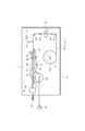
- the paper tube manufacturing machine includes a main frame 10, and a web roll WR is rotatably supported via a bobbin holder 12 below the main frame 10.
- the bobbin holder 12 is shown only by the hollow shaft in the center.
- the web roll WR can feed out the web-like paper material P along the feeding path 14, and in this embodiment, the paper material P is sufficiently thicker than the web when compared with the web used in the cigarette. Moreover, it has high rigidity. Specifically, the paper material P has a width of about 16.7 to 28.1 mm, a basis weight of 100 to 300 g / m 2 , a thickness of 150 to 500 ⁇ m, and a density of 0.5 g / cm 3 or more.
- the feeding path 14 is defined by a plurality of guide rollers 16 and connects between the web roll WR and the web bending device 18.
- the web bending device 18 is disposed above the web roll WR and supported by the main frame 10. Therefore, the feeding path 14 extends horizontally from the web roll WR in the right direction as viewed in FIG. 1, and then extends upward to the reference height level of the web bending device 18 and horizontally to the left side to the web bending device 18. It extends to.
- the web bending apparatus 18 includes a molding bed 20, which extends horizontally at a reference height level.
- a part of an endless garniture belt 22 is disposed on the molding bed 20.
- the garniture belt 22 has an outward path portion that extends horizontally on the molding bed 20 and a return path portion that deviates from the molding bed 20.
- the return path portion of the garniture belt 22 is guided by a plurality of guide rollers 24 and is wound around the drive drum 26 at a predetermined wrapping angle.
- the drive drum 26 is connected to an output shaft of an electric motor (not shown), and is rotated at a constant peripheral speed by the driving force of the electric motor. Such rotation of the drive drum 26 causes the traveling portion of the garniture belt 22 to travel at a constant speed from right to left as viewed in FIG.
- the paper material P is led from the feeding path 14 described above onto the forward path portion of the garniture belt 22 and is superimposed on the garniture belt 22. Therefore, the paper material P travels with the forward path portion due to the frictional force with the forward path portion of the garniture belt 22, and this travel feeds the paper material P from the web roll WR at a constant speed.
- the bobbin holder 12 described above incorporates a brake (not shown), and this brake applies a predetermined tension to the paper material P.
- a groove forming device 28 is disposed in the feeding path 14, and details of the groove forming device 28 are shown in FIGS.
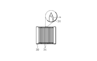
- the groove forming device 28 includes a cutting roller 30 and a receiving roller 32.
- the cutting roller 30 and the receiving roller 32 are arranged so as to sandwich the paper material P on the feeding path 14 and are rotatably supported by the main frame 10.
- the cutting roller 30 has a plurality of circular blades 34 projecting from the outer peripheral surface thereof, and these circular blades 34 are arranged at predetermined intervals in the axial direction of the cutting roller 30.
- Each circular blade 34 has an acute edge, and the angle of the edge, that is, the edge angle ⁇ is, for example, 14 to 30 °.
- the receiving roller 32 has a smooth outer peripheral surface.
- each circular blade 34 has one side of the paper material P as shown in FIG. V-shaped cut grooves G are respectively formed in the cut grooves G, and the cut grooves G have an opening angle ⁇ corresponding to the cutting edge angle ⁇ . Therefore, the paper material P after passing through the groove forming device 28 becomes a paper web PW having a plurality of cut grooves G.
- the plurality of cut grooves G extend continuously in the feeding direction of the paper material P, that is, in the longitudinal direction thereof, and increases the flexibility of the paper web PW.
- the cut groove G is formed on the inner surface of the paper material P facing upward when the paper web PW is superimposed on the signature belt 22, but the paper groove P of the paper material P on the side of the signature belt 22 is formed. It may be formed on the outer surface.
- the cut groove G is formed on the inner surface of the paper material P, as will be apparent from the following description, when the paper tube is formed from the paper web PW, the cut groove G has two inner surfaces facing each other. Therefore, such a paper tube can obtain higher rigidity than a paper tube made of a paper web in which a cut groove G is formed on the outer surface of the paper material P.
- the notches G has 60-90% of the depth D G of the thickness T of the paper material P, also, spacing S between adjacent notches G is 2mm or less. Spacing S is determined by the spacing between the circular blade 34 adjacent to each other, the depth D G is determined by the gap between the outer peripheral surface of the receiving and cutting edge of the circular blade 34 roller 32. In this embodiment, the gap can be adjusted.
- the cutting roller 30 and the receiving roller 32 can be formed in the paper material P by merely being rotatably supported by the main frame 10.
- the cutting roller 30 is forcibly rotated in accordance with the feeding direction of the paper web PW, and the peripheral speed of the cutting edge in the circular blade 34 is increased. It is preferable to match the feeding speed of the paper material P.
- a speed difference may be provided between the peripheral speed of the cutting roller 30 and the feeding speed of the paper web PW, or the rotation direction of the cutting roller 30 and the paper web PW. These feeding directions may be opposite to each other.
- the roller shaft of the cutting roller 30 is connected to a drive source, that is, an electric motor 30M .
- the electric motor 30 M is electrically connected to the rotary encoder 38, the rotary encoder 38 is attached to the drum shaft of the aforementioned driving drum 26.
- the rotary encoder 38 sends a rotation signal indicating the peripheral speed of the drive drum 26 to the electric motor 30 M, thereby, the electric motor 30 M is the peripheral speed of the drive drum 26, i.e., circular blade 34 to the feeding speed of the paper material P
- the cutting roller 30 is rotated so that the peripheral speeds of the cutting edges coincide with each other.
- the paper material P after passing through the groove forming device 28 becomes a paper web PW having a plurality of cut grooves G. That is, in the case of the present embodiment, the aforementioned feeding path 14 is divided into an upstream part and a downstream part with the groove forming device 28 as a boundary, and the upstream part defines a guide path 14 U for guiding the paper material P, downstream portion defines the transfer path 14 D to transport towards the web bending apparatus 18 the paper web PW.
- traveling guides 40 are arranged immediately upstream and downstream of the groove forming device 28, respectively, and these traveling guides 40 guide the traveling of the paper material P and the paper web PW. This helps to stabilize the formation of the above-mentioned cut groove G.
- Web bending apparatus 18 further includes a coating 42 of adhesive disposed transport path 14 D, the details of the applicator 42 is shown in FIG.
- the applicator 42 includes a coating nozzle 44, the coating nozzle 44 is immediately above the paper web PW on the transport path 14 D, is disposed downward.
- the coating nozzle 44 is disposed immediately above the side edge E 1 located on the near side as viewed in FIG. 3 among the side edges E 1 and E 2 of the paper web PW.
- the application nozzle 44 is connected to an electric pump 46, which is connected to an adhesive tank 48. While the electric pump 46 for sucking the adhesive from the tank 48, feed, thereby the coating nozzle 44 of the adhesive sucked, the coating nozzle 44 discharges the adhesive towards the paper web PW, a side edge E 1 of the paper web PW Apply adhesive continuously.
- the paper web PW after passing through the coating nozzle 44 has an adhesive layer A which extends along their side edges E 1.
- the width of the adhesive layer A is, for example, about 1 to 3 mm.
- Such an adhesive layer A is preferably formed of a certain amount of adhesive per unit length.
- the electric pump 46 is electrically connected to a controller 50 that controls the amount of adhesive discharged from the application nozzle 44.
- the controller 50 receives the rotation signal transmitted from the rotary encoder 38 and supplies a coating amount signal proportional to the traveling speed of the paper web PW to the electric pump 46.
- the electric pump 46 is driven in accordance with the application amount signal, and causes the adhesive to be discharged from the application nozzle 44 at a discharge amount corresponding to the traveling speed of the paper web PW.
- the applicator 42 further includes a cradle 52 which is disposed immediately below the transport path 14 D.
- the pedestal 52 guides the travel of the paper web PW and maintains the air force between the side edge E of the paper web PW and the application nozzle 44 at a constant level.
- the adhesive is preferably a paste for food-related materials.
- the adhesive is selected from the group of CMC-Na, vinyl acetate, EVA, pullulan and pectin.
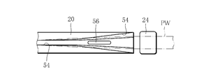
- FIG. 6 is a plan view showing the starting end portion of the molding bed 20 described above.
- a molding groove 54 is formed on the upper surface of the molding bed 20.
- the molding groove 54 extends over the entire length of the molding bed 20, and is opened in a fan shape at the start end of the molding bed 20.
- the width of the forming groove 54 is gradually decreased from the start end of the forming bed 20 toward the end thereof, and has a constant width in a region excluding the start end portion of the forming bed 20.
- the above-described forming groove 54 guides the travel of the garniture belt 22 and the paper web PW. Therefore, when the garniture belt 22 and the paper web PW advance in the molding groove 54, the garniture belt 22 and the paper web PW are formed into a U-shape when viewed in cross section by the molding groove 54, as is apparent from FIG.
- the above-described forming groove 54 guides the travel of the garniture belt 22 and the paper web PW. Therefore, when the garniture belt 22 and the paper web PW advance in the molding groove 54, the garniture belt 22 and the paper web PW are formed into a U-shape when viewed in cross section by the molding groove 54, as is apparent from FIG.
- the web bending apparatus 18 further includes a press roller 56.
- the press roller 56 is rotatably supported at the start end of the forming bed 20.
- the lower portion of the press roller 56 is positioned in the forming groove 54 and presses the paper web PW in the process of being formed into a U shape together with the signature belt 22 against the bottom of the forming belt 54, that is, the forming groove 54.
- Such a press roller 56 is useful for increasing the frictional force between the paper web PW and the signature belt 22 and causing the paper web PW to travel together with the signature belt 22. Therefore, in order to further increase the above-described frictional force, it is preferable that the outer peripheral surface of the press roller 56 is covered with a friction layer 58 as shown in FIG. 8, for example, the friction layer 58 is made of an elastic body such as rubber. Can be formed.
- the press roller 56 When the paper web PW and the signature belt 22 pass through the press roller 56, the press roller 56 is dragged and rotated by the paper web PW. However, in order to ensure stable running of the paper web PW, it is preferable that the press roller 56 be forcibly rotated at a peripheral speed that matches the running speed of the paper web PW. Therefore, the driving source roller shaft of the press roller 56, i.e., is connected to the electric motor 56 M, the electric motor 56 M is based on the rotation signal described above, to rotate the press roller 56.
- the press roller 56 described above can be arranged in the vicinity of the starting end of the forming bed 20 so as to sandwich the paper web PW and the signature belt 22 in cooperation with the guide roller 24.
- the rigidity when the paper web PW is formed in a U shape is higher than the rigidity when the paper web is flat. Therefore, the press roller 56 disposed in the forming groove 54 can apply a strong feeding force to the paper web PW without undesirably deforming the paper web PW.
- the above-described web bending device 18 further includes a tube forming section 60, which is disposed immediately above the forming bed 20 downstream of the press roller 56.
- FIG. 9 shows a plan view of the tube forming section 60.
- the tube forming section 60 includes a first forming guide 62 and a second forming guide 64, and the first and second forming guides 62 and 64 extend along the running direction of the paper web PW.
- the first molded guide 62 is viewed in the molding bed 20 ⁇ , i.e., arranged on the side edge E 2 side of the paper web PW, contrary, the second forming guide 64 is first viewed in the running direction of the paper web PW It is and disposed on a side edge E 1 side of the paper web PW immediately downstream of the forming guide 62.
- the first and second molding guides 62 and 64 have ceiling surfaces 62c and 64c for the molding groove 54 on their lower surfaces, respectively, and these ceiling surfaces 62c and 64c are approximately 1/4 of a circular shape. It has an arc shape. These ceiling surfaces 62c and 64c are expanded at the starting ends of the corresponding forming guides, and are gradually narrowed down to an arc shape from the starting ends toward the end of the forming guides.
- the side surface S 2 of the paper web PW of the side edge E 2 side enters the first shaping guide 62 with crab char belt 22 the side S 2 is guided to the ceiling surface 62c via a crab char belt 22 is curved in an arc shape.
- the side surface S 1 of the paper web PW on the side edge E 1 side enters the second shaping guide 64 with crab char belt 22, the side surface S 1 is guided to the ceiling surface 64c via a crab char belt 22, Curved into an arc shape.
- FIG. 11 shows a state in which the side surface S 1 is bent following the side surface S 2 .
- the side edge E 1 of the side surface S 1 is already superimposed on the side edges E 2 side S 2 which is curved in an arc shape, these side edges E 1, E 2 is the lap portion L is formed. Since the above-mentioned are to the side edge E 1 such that the adhesive layer A (see FIG. 5) is formed, the side edges E 1, E 2 to form the lap portion L are bonded together through an adhesive layer A The
- the paper web PW is formed into a hollow tube HT having a diameter of 5 to 8 mm, and this hollow tube HT is continuously sent out from the tube forming section 60.
- the tube forming section 60 has basically the same structure as the rod forming section of a manufacturing machine that manufactures cigarette rods and filter rods.
- a preforming guide 66 is disposed immediately upstream of the tube forming section 60.
- the preforming guide 66 has, for example, a half shape of a tapered tube, and a forming groove 54 is formed on the lower surface thereof.
- the ceiling surface 66c expands at the start end of the preforming guide 66, and is narrowed down to a semicircle toward the end of the preforming guide 66.
- the preforming guide 66 When the paper web PW bent in the U-shape is transferred by the belt 22 and passes through the preforming guide 66, the side surfaces S 1 and S 2 of the paper web PW both enter the preforming guide 66, and At the same time, the preforming guide 66 is curved into an arc shape by the ceiling surface 66c.
- the preforming guide 66 preliminarily curves the side surfaces S 1 and S 2 of the paper web PW upstream of the tube forming section 60, and both of these side surfaces S 1 and S 2 are connected via the garniture belt 22.
- Each running resistance is given downstream of the preforming guide 66, the first shaping guide 62 side S 2 of the paper web PW is enters the tube forming section 60, the running resistance is applied to one side of the paper web PW via the side S 2 Even if this is done, the running of the paper web PW does not become unstable.
- preforming guide 66 is provided with bending ridges on the side surfaces S 1 and S 2 of the paper web PW, the side surfaces S 1 and S 2 enter the tube forming section 60 more smoothly.
- the press roller 56 is the electric motor 56 M described above, the press roller 56 is forced to feed the paper web PW toward the tube forming section 60.
- preform guides 66 are hollow tubes HT mentioned above Useful for stable molding.
- a dryer 68 is disposed immediately downstream of the tube forming section 60 described above.
- the dryer 68 includes a block-shaped electric heater 70.
- the heater 70 is disposed immediately above the forming groove 54 and extends along the traveling direction of the paper web PW.
- a heating rib 72 protrudes integrally from the lower surface of the heater 70, and this heating rib 72 also extends in the running direction of the paper web PW.
- the lap portion L of the hollow tube HT delivered from the tube forming section 60 is pressed against the heating rib 72 and simultaneously slidably contacts the heating rib 72. Therefore, the lap portion L is dried by receiving heat from the heating rib 72, whereby the side edges E 1 and E 2 forming the lap portion L are firmly bonded to each other.
- regulation guides 74 are arranged on both sides of the heater 70, and these regulation guides 74 extend in the traveling direction of the paper web PW.
- the hollow tube HT delivered from the tube forming section 60 is sandwiched by restriction guides 74 from both sides thereof, and comes into sliding contact with the restriction guides 74.
- the regulation guide 74 prevents the hollow tube HT from expanding in the width direction. Therefore, at the time of the drying process of the wrap part L, the side edges E 1 and E 2 forming the lap part L are not canceled and the side edges E 1 and E 2 are well bonded to each other.
- the basis weight, thickness and running speed of the paper web PW, and the coating amount of the adhesive layer A are 200 g / m 2 , 250 ⁇ m, 2 m / min (33.3 mm / sec), 5 to 10 mg / sec, respectively.
- the heating temperature of the heater 70 required for the drying process of the lap portion L is about 170 ° C., although it depends on the type of adhesive.
- the heating temperature required for the heater 70 is obtained from the above equation. It is desirable that the heating temperature be set higher than the heating temperature HT.
- a cutting device 76 is arranged downstream of the web bending device 18.
- the hollow tube HT that has passed through the web bending device 18 passes through the cutting device 76.
- the cutting device 76 cuts the hollow tube HT by a predetermined length, and at this point, the individual paper tubes PT are separated. It is formed.
- Table 1 below shows the relationship between the depth of the cut groove G of the paper web PW and the fold of the paper web PW that appears on the outer peripheral surface of the formed paper tube PT.
- the paper web PW of the paper tube PT had a basis weight of 200 g / m 2 , a thickness of 250 ⁇ m, a density of 083 g / m 3 , and the diameter of the paper tube PT was 7.2 mm.
- the paper tube PT has a smooth outer peripheral surface with no folds appearing on the outer peripheral surface. Tube PT was obtained. Incidentally, 0% depth D G indicates that the paper web PW has no notches G.
- the folding of the paper tube PT is likely to occur in the forming process, particularly in the process of passing the U-shaped paper web PW through the tube forming section 60. That is, when the flexibility of the side surfaces S 1 and S 2 in the paper web PW is low, the side surfaces S 2 and S 1 cannot smoothly enter the first forming guides 62 and 64, and the forming guides 62, It bends at the entrance of 64.
- FIG. 13 shows the relationship between the depth of the cut groove G and the radial strength of the paper tube PT
- FIG. 14 shows the relationship between the depth of the cut groove G and the strength of the paper tube PT in the axial direction. 13 and 14 also show the strength of the cigarette and the cigarette filter.
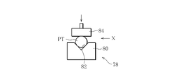
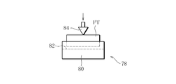
- the result of FIG. 13 was obtained by the first test apparatus 78 shown in FIGS. 15 and 16.
- the first test device 78 includes a cradle 80, and the cradle 80 has a V-shaped groove 82 on its upper surface.
- the paper tube PT to be tested is held in the V-shaped groove 82 in a horizontal posture.
- the first test device 78 further includes a pusher 84, and the pusher 84 is disposed above the cradle 80 so as to be movable up and down.
- the pusher 84 is lowered toward the paper tube PT held on the cradle 80 and pushes the outer peripheral surface of the paper tube PT to a predetermined distance in the radial direction of the paper tube PT.
- the first test apparatus 78 measured the reaction force received from the paper tube PT via the pusher 84 as the radial strength of the paper tube PT.
- the radial strength of the cigarette and filter was also measured in the same manner as the paper tube PT.
- the test device 86 includes a flat cradle 88, and the paper tube PT to be tested is placed on the cradle 88 in a vertical posture.
- the test device 86 also includes a pusher 90, which can also be raised and lowered.
- the pusher 90 is lowered from above the paper tube PT toward the upper end of the paper tube PT, and pushes the upper end of the paper tube PT to a predetermined distance in the axial direction of the paper tube PT.
- the test apparatus 86 measures the reaction force received from the paper tube PT via the pusher 90 as the strength in the axial direction of the paper tube PT.
- strength of the cigarette and the axial direction of a filter was also measured like the paper tube PT.
- the strength of the paper tube PT having the cut groove G tends to be slightly lower than the strength of the paper tube PT not having the cut groove G. .
- the difference between these strengths is slight.
- the strength of the paper tube PT having the cut groove G is sufficiently higher than the strength of the cigarette or the filter. This means that the paper tube PT is rigid enough not to be easily crushed by a force that allows the user to pinch the paper tube PT lightly between fingers.
- the paper tube PT having the cut groove G has sufficient rigidity in both the radial direction and the axial direction, while the above-described paper tube manufacturing is performed without generating a fold in the outer peripheral surface as described above. Can be manufactured continuously on a machine. Therefore, the paper tube PT of this embodiment is suitable for the pipe member of the flavor suction tool described above.
- the present invention is not limited to the paper tube manufacturing machine of the above-described embodiment and the paper tube manufacturing method performed by the paper tube manufacturing machine.
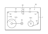
- the paper tube making machine described above forms the paper web PW on the feeding path 14, but the paper web PW can be formed by a web making machine different from the paper tube making machine, and FIG. An example is shown.
- the web making machine is provided with a web roll WR 1 paper material P, the web roll WR 1 is connected to the bobbin holder 12 through the traveling path 92.
- the travel path 92 is defined by a large number of guide rollers 94.
- the bobbin holder 12 is connected to an electric motor 96, and the electric motor 96 rotates the bobbin holder 12 so that the travel of the paper material P (paper web PW) is constant.
- the paper material P paper web PW
- the fed paper material P travels along the travel path 92 and is wound around the bobbin holder 12.
- the aforementioned groove forming device 28 is disposed in the travel path 92.
- the groove forming device 28 forms a plurality of cut grooves G in the paper material P as described above, and forms the paper material P into the paper web PW. Therefore, the paper web PW is wound around the bobbin holder 12, thereby, the web roll WR 2 of the paper web PW is formed.
- Such a web roll WR 2 is attached to the paper tube manufacturing machine of FIG. 1 and used for manufacturing the paper tube PT. In this case, needless to say, the groove forming device 28 is removed from the paper tube manufacturing machine.
- 14 Feeding path, 14 U : Guide path, 14 D : Transfer path, 18: Web bending apparatus, 20: Molding bed, 22: Ganiture belt, 28: Groove forming apparatus, 30: Cutting roller, 30M : Electric motor (Drive source), 32: receiving roller, 34: circular blade, 42: applicator, 54: forming groove, 56: press roller, 56 M : electric motor (drive source), 60: tube forming section, 66: pre-forming Guide: 68: Dryer, 70: Heater, 72: Heating rib, 74: Regulation guide, ⁇ : Cutting edge angle, G: Cutting groove, L: Lapping part, P: Paper material, PT: Paper tube, PW: Paper web
Landscapes
- Engineering & Computer Science (AREA)
- Mechanical Engineering (AREA)
- Making Paper Articles (AREA)
- Replacement Of Web Rolls (AREA)
- Folding Of Thin Sheet-Like Materials, Special Discharging Devices, And Others (AREA)
Abstract
Priority Applications (6)
| Application Number | Priority Date | Filing Date | Title |
|---|---|---|---|
| RU2015120594A RU2611276C2 (ru) | 2012-10-31 | 2012-10-31 | Машина для производства бумажной трубки, способ производства бумажной трубки и бумажная трубка, произведенная этим способом |
| UAA201505264A UA110914C2 (uk) | 2012-10-31 | 2012-10-31 | Машина для виробництва паперової трубки, спосіб виробництва паперової трубки і паперова трубка, виконана цим способом |
| JP2014544119A JP5921008B2 (ja) | 2012-10-31 | 2012-10-31 | 紙管製造機及びその製造方法 |
| EP12887644.8A EP2845499B1 (fr) | 2012-10-31 | 2012-10-31 | Machine à fabriquer des tubes de papier, procédé de fabrication de ces derniers et tube de papier fabriqué par ledit procédé de fabrication |
| CN201280074189.8A CN104411190B (zh) | 2012-10-31 | 2012-10-31 | 纸管制造机、其制造方法和利用该制造方法制造的纸管 |
| PCT/JP2012/078178 WO2014068703A1 (fr) | 2012-10-31 | 2012-10-31 | Machine à fabriquer des tubes de papier, procédé de fabrication de ces derniers et tube de papier fabriqué par ledit procédé de fabrication |
Applications Claiming Priority (1)
| Application Number | Priority Date | Filing Date | Title |
|---|---|---|---|
| PCT/JP2012/078178 WO2014068703A1 (fr) | 2012-10-31 | 2012-10-31 | Machine à fabriquer des tubes de papier, procédé de fabrication de ces derniers et tube de papier fabriqué par ledit procédé de fabrication |
Publications (1)
| Publication Number | Publication Date |
|---|---|
| WO2014068703A1 true WO2014068703A1 (fr) | 2014-05-08 |
Family
ID=50626671
Family Applications (1)
| Application Number | Title | Priority Date | Filing Date |
|---|---|---|---|
| PCT/JP2012/078178 Ceased WO2014068703A1 (fr) | 2012-10-31 | 2012-10-31 | Machine à fabriquer des tubes de papier, procédé de fabrication de ces derniers et tube de papier fabriqué par ledit procédé de fabrication |
Country Status (6)
| Country | Link |
|---|---|
| EP (1) | EP2845499B1 (fr) |
| JP (1) | JP5921008B2 (fr) |
| CN (1) | CN104411190B (fr) |
| RU (1) | RU2611276C2 (fr) |
| UA (1) | UA110914C2 (fr) |
| WO (1) | WO2014068703A1 (fr) |
Cited By (10)
| Publication number | Priority date | Publication date | Assignee | Title |
|---|---|---|---|---|
| CN105686073A (zh) * | 2014-12-16 | 2016-06-22 | 豪尼机械制造股份公司 | 烟草加工工业的双层的管子以及用于制造这样的管子的装置和方法 |
| CN109278361A (zh) * | 2018-11-15 | 2019-01-29 | 昆山科瑞森机电设备有限公司 | 一种纸纸管的制造工艺与设备 |
| CN109367120A (zh) * | 2018-11-01 | 2019-02-22 | 江西盛峰日用品有限公司 | 一种用于纸杯生产的烘干、裁切和码放一体装置 |
| CN110561837A (zh) * | 2019-08-08 | 2019-12-13 | 武汉市艺茂机械有限公司 | 一种轴向纸管卷制成型装置 |
| CN110973697A (zh) * | 2019-12-31 | 2020-04-10 | 武汉力诚生物科技有限公司 | 一种新型植物多糖凝胶棒的成型装置及制造方法 |
| WO2020100879A1 (fr) * | 2018-11-14 | 2020-05-22 | 日本たばこ産業株式会社 | Segment contenant du tabac et son procédé de production, article à fumer chauffant non combustible et système pour fumer chauffant non combustible |
| EP3821721A1 (fr) * | 2016-01-26 | 2021-05-19 | G.D S.p.A. | Procédé et machine pour fabriquer des morceaux d'une tige tubulaire cylindrique multicouche utilisée pour fabriquer des articles pour fumeur sensiblement cylindriques |
| DE102022116184A1 (de) * | 2022-06-29 | 2024-01-04 | Körber Technologies Gmbh | Maschine der Tabak verarbeitenden Industrie zum Herstellen eines Strangs sowie Verfahren zum Herstellen eines Strangs der Tabak verarbeitenden Industrie |
| DE102022116185A1 (de) * | 2022-06-29 | 2024-01-04 | Körber Technologies Gmbh | Maschine und Verfahren der Tabak verarbeitenden Industrie zum Herstellen eines Strangs oder Papierfilters sowie Verwendung der Maschine |
| WO2025017878A1 (fr) * | 2023-07-19 | 2025-01-23 | 日本たばこ産業株式会社 | Dispositif et procédé de fabrication de tige pour article d'inhalation d'arôme |
Families Citing this family (17)
| Publication number | Priority date | Publication date | Assignee | Title |
|---|---|---|---|---|
| KR102022302B1 (ko) * | 2016-10-25 | 2019-11-04 | 태영산업 주식회사 | 담배용 필터의 제조장치 |
| DE102016124051A1 (de) | 2016-12-12 | 2018-06-14 | Hauni Maschinenbau Gmbh | Doppellagiges Röhrchen der Tabak verarbeitenden Industrie sowie Verfahren zur Herstellung eines derartigen Röhrchens |
| DE102017101929A1 (de) | 2017-02-01 | 2018-08-02 | Hauni Maschinenbau Gmbh | Verfahren zum Herstellen eines Strangs der Tabak verarbeitenden Industrie sowie Strangformungsvorrichtung |
| DE102017114910A1 (de) * | 2017-07-04 | 2019-01-10 | Hauni Maschinenbau Gmbh | Verfahren zum Herstellen von Hohlrohren der Tabak verarbeitenden Industrie sowie Formatvorrichtung |
| KR102042619B1 (ko) * | 2018-07-18 | 2019-11-11 | 제이제이인더스트리 | 종이 빨대 제조방법 및 그 장치 |
| CN109156889B (zh) * | 2018-07-23 | 2021-05-25 | 山东中烟工业有限责任公司 | 一种空心卷烟生产制作方法 |
| DE102018121618A1 (de) * | 2018-09-05 | 2020-03-05 | Hauni Maschinenbau Gmbh | Trennvorrichtung und Verfahren zum Auftrennen einer Flachbahn in eine Vielzahl von verbundenen Streifen sowie Vorrichtung und Verfahren zum Herstellen eines Strangs |
| KR102181023B1 (ko) * | 2018-10-26 | 2020-11-19 | 김희중 | 지제(紙材)빨대, 이 지제 빨대의 제조장치 및 제조 방법 |
| KR102054114B1 (ko) * | 2019-07-23 | 2019-12-09 | 주식회사 그린맥스 | 종이빨대 제조장치 및 이에 의해 제조된 종이빨대 |
| WO2021132751A1 (fr) * | 2019-12-24 | 2021-07-01 | 김희중 | Paille en papier, appareil et procédé de fabrication d'une telle paille en papier |
| DE102020102722A1 (de) * | 2020-02-04 | 2021-08-05 | Hauni Maschinenbau Gmbh | Trinkhalmherstellung |
| DE102020107088A1 (de) * | 2020-03-16 | 2021-09-16 | Hauni Maschinenbau Gmbh | Vorrichtung zur Herstellung von Hohlrohren, insbesondere Trinkhalmen, und Verfahren hierzu |
| CN113925202B (zh) * | 2021-11-12 | 2023-10-31 | 南通金源新材料有限公司 | 一种功能管的制备方法及功能管 |
| KR102759644B1 (ko) * | 2021-11-19 | 2025-02-04 | 주식회사 케이티앤지 | 가향 시트를 포함하는 지관 및 이를 포함하는 흡연 물품 |
| IT202200019926A1 (it) * | 2022-09-28 | 2024-03-28 | Gd Spa | Macchina e procedimento per la formazione di tubolari multistrato |
| IT202300016221A1 (it) * | 2023-08-01 | 2025-02-01 | Gd Spa | Macchina e metodo per la produzione di articoli tubolari e articolo tubolare |
| IT202300022359A1 (it) | 2023-10-25 | 2025-04-25 | Gd Spa | Macchina e metodo per la produzione di articoli tubolari e articolo tubolare |
Citations (5)
| Publication number | Priority date | Publication date | Assignee | Title |
|---|---|---|---|---|
| JPH0697982B2 (ja) * | 1989-09-14 | 1994-12-07 | 株式会社三條機械製作所 | 紙製フイルターロッド製造装置 |
| JP3782394B2 (ja) * | 2000-09-08 | 2006-06-07 | 日本たばこ産業株式会社 | 低延焼性シガレット製造方法及び低延焼性シガレット製造装置 |
| JP4530371B2 (ja) * | 2004-12-15 | 2010-08-25 | 日本たばこ産業株式会社 | 棒状喫煙物品の製造機 |
| JP2010535530A (ja) | 2007-08-10 | 2010-11-25 | フィリップ・モーリス・プロダクツ・ソシエテ・アノニム | 蒸留ベースの喫煙物品 |
| JP4740506B2 (ja) * | 2000-03-23 | 2011-08-03 | フィリップ・モーリス・プロダクツ・インコーポレイテッド | 電気喫煙システムと方法 |
Family Cites Families (8)
| Publication number | Priority date | Publication date | Assignee | Title |
|---|---|---|---|---|
| DE647034C (de) * | 1935-06-19 | 1937-06-25 | Jean Angeloglou | Maschine zum Herstellen von Zigarettenhuelsen |
| DE3145967A1 (de) * | 1981-11-20 | 1983-06-01 | Hoechst Ag, 6230 Frankfurt | Verfahren und vorrichtung zur bildung eines schlauches aus einer flachen bahn |
| DE3629083A1 (de) * | 1986-08-27 | 1988-03-10 | Hauni Werke Koerber & Co Kg | Verfahren und vorrichtung zur herstellung von zigarettenhuelsen |
| US5169481A (en) * | 1990-03-16 | 1992-12-08 | Philip Morris Incorporated | Apparatus making thin laminate structures and forming the structures into lightweight, thin-walled tubes |
| FI86160C (sv) * | 1990-09-04 | 1993-03-31 | Partek Ab | Förfarande för tillverkning av sandwichelement bestående av en kärna a v mineralullslameller och ytskikt exempelvis av plåt samt en anordning för utförande av förfarandet |
| DE10317937A1 (de) * | 2003-04-17 | 2004-11-04 | Saint-Gobain Isover G+H Ag | Verfahren zur Herstellung von Rohrschalen aus Mineralwolle sowie derartige Rohrschalen |
| ITBO20040165A1 (it) * | 2004-03-22 | 2004-06-22 | Gd Spa | Macchina confezionatrice di sigarette |
| CN104010532B (zh) * | 2011-12-21 | 2016-08-17 | 日本烟草产业株式会社 | 纸管和使用该纸管的香味吸引具 |
-
2012
- 2012-10-31 WO PCT/JP2012/078178 patent/WO2014068703A1/fr not_active Ceased
- 2012-10-31 UA UAA201505264A patent/UA110914C2/uk unknown
- 2012-10-31 EP EP12887644.8A patent/EP2845499B1/fr not_active Not-in-force
- 2012-10-31 JP JP2014544119A patent/JP5921008B2/ja not_active Expired - Fee Related
- 2012-10-31 CN CN201280074189.8A patent/CN104411190B/zh not_active Expired - Fee Related
- 2012-10-31 RU RU2015120594A patent/RU2611276C2/ru active
Patent Citations (5)
| Publication number | Priority date | Publication date | Assignee | Title |
|---|---|---|---|---|
| JPH0697982B2 (ja) * | 1989-09-14 | 1994-12-07 | 株式会社三條機械製作所 | 紙製フイルターロッド製造装置 |
| JP4740506B2 (ja) * | 2000-03-23 | 2011-08-03 | フィリップ・モーリス・プロダクツ・インコーポレイテッド | 電気喫煙システムと方法 |
| JP3782394B2 (ja) * | 2000-09-08 | 2006-06-07 | 日本たばこ産業株式会社 | 低延焼性シガレット製造方法及び低延焼性シガレット製造装置 |
| JP4530371B2 (ja) * | 2004-12-15 | 2010-08-25 | 日本たばこ産業株式会社 | 棒状喫煙物品の製造機 |
| JP2010535530A (ja) | 2007-08-10 | 2010-11-25 | フィリップ・モーリス・プロダクツ・ソシエテ・アノニム | 蒸留ベースの喫煙物品 |
Non-Patent Citations (1)
| Title |
|---|
| See also references of EP2845499A4 * |
Cited By (15)
| Publication number | Priority date | Publication date | Assignee | Title |
|---|---|---|---|---|
| CN105686073A (zh) * | 2014-12-16 | 2016-06-22 | 豪尼机械制造股份公司 | 烟草加工工业的双层的管子以及用于制造这样的管子的装置和方法 |
| EP3821721A1 (fr) * | 2016-01-26 | 2021-05-19 | G.D S.p.A. | Procédé et machine pour fabriquer des morceaux d'une tige tubulaire cylindrique multicouche utilisée pour fabriquer des articles pour fumeur sensiblement cylindriques |
| CN109367120B (zh) * | 2018-11-01 | 2020-04-28 | 江西盛峰日用品有限公司 | 一种用于纸杯生产的烘干、裁切和码放一体装置 |
| CN109367120A (zh) * | 2018-11-01 | 2019-02-22 | 江西盛峰日用品有限公司 | 一种用于纸杯生产的烘干、裁切和码放一体装置 |
| JPWO2020100879A1 (ja) * | 2018-11-14 | 2021-09-02 | 日本たばこ産業株式会社 | たばこ含有セグメント及びその製造方法、非燃焼加熱喫煙物品、並びに非燃焼加熱喫煙システム |
| WO2020100879A1 (fr) * | 2018-11-14 | 2020-05-22 | 日本たばこ産業株式会社 | Segment contenant du tabac et son procédé de production, article à fumer chauffant non combustible et système pour fumer chauffant non combustible |
| KR20210063415A (ko) * | 2018-11-14 | 2021-06-01 | 니뽄 다바코 산교 가부시키가이샤 | 담배 함유 세그먼트 및 그 제조 방법, 비연소 가열 흡연 물품, 그리고 비연소 가열 흡연 시스템 |
| JP7034329B2 (ja) | 2018-11-14 | 2022-03-11 | 日本たばこ産業株式会社 | たばこ含有セグメント及びその製造方法、非燃焼加熱喫煙物品、並びに非燃焼加熱喫煙システム |
| KR102660689B1 (ko) | 2018-11-14 | 2024-04-26 | 니뽄 다바코 산교 가부시키가이샤 | 담배 함유 세그먼트 및 그 제조 방법, 비연소 가열 흡연 물품, 그리고 비연소 가열 흡연 시스템 |
| CN109278361A (zh) * | 2018-11-15 | 2019-01-29 | 昆山科瑞森机电设备有限公司 | 一种纸纸管的制造工艺与设备 |
| CN110561837A (zh) * | 2019-08-08 | 2019-12-13 | 武汉市艺茂机械有限公司 | 一种轴向纸管卷制成型装置 |
| CN110973697A (zh) * | 2019-12-31 | 2020-04-10 | 武汉力诚生物科技有限公司 | 一种新型植物多糖凝胶棒的成型装置及制造方法 |
| DE102022116184A1 (de) * | 2022-06-29 | 2024-01-04 | Körber Technologies Gmbh | Maschine der Tabak verarbeitenden Industrie zum Herstellen eines Strangs sowie Verfahren zum Herstellen eines Strangs der Tabak verarbeitenden Industrie |
| DE102022116185A1 (de) * | 2022-06-29 | 2024-01-04 | Körber Technologies Gmbh | Maschine und Verfahren der Tabak verarbeitenden Industrie zum Herstellen eines Strangs oder Papierfilters sowie Verwendung der Maschine |
| WO2025017878A1 (fr) * | 2023-07-19 | 2025-01-23 | 日本たばこ産業株式会社 | Dispositif et procédé de fabrication de tige pour article d'inhalation d'arôme |
Also Published As
| Publication number | Publication date |
|---|---|
| CN104411190A (zh) | 2015-03-11 |
| UA110914C2 (uk) | 2016-02-25 |
| EP2845499A4 (fr) | 2016-01-20 |
| RU2611276C2 (ru) | 2017-02-21 |
| EP2845499B1 (fr) | 2019-10-16 |
| CN104411190B (zh) | 2016-10-12 |
| JP5921008B2 (ja) | 2016-05-24 |
| JPWO2014068703A1 (ja) | 2016-09-08 |
| RU2015120594A (ru) | 2016-12-20 |
| EP2845499A1 (fr) | 2015-03-11 |
Similar Documents
| Publication | Publication Date | Title |
|---|---|---|
| JP5921008B2 (ja) | 紙管製造機及びその製造方法 | |
| JP6401359B2 (ja) | 皺寄せシート材料の連続ウェブを供給するための装置及び方法 | |
| JP7641256B2 (ja) | エアロゾル生成材料ロッドセグメント | |
| JP7674406B2 (ja) | エアロゾル発生材からなるロッドの製造装置および製造方法 | |
| JP2022516532A (ja) | エアロゾル発生材からなるストランドを搬送するためのコンベアおよび方法、エアロゾル発生材からなるロッドの製造装置および方法 | |
| JP7301097B2 (ja) | 喫煙者商品の一部を形成するよう意図された半完成品を生産する装置および方法 | |
| CN219835175U (zh) | 一种用于低强度烟叶片材精确切割的切割装置 | |
| JP2018121526A (ja) | 喫煙物品用棒状物品の製造機およびその製造方法 | |
| JP2005151989A (ja) | 冷却装置 | |
| CN104872818B (zh) | 用于制造烟草加工行业的条的方法和装置 | |
| WO2015022721A1 (fr) | Outil de découpe de matériau en feuille et procédé de découpe de matériau en feuille | |
| CN116274159B (zh) | 一种低强度柔性连续烟条的喂料装置及喂料方法 | |
| JP5910240B2 (ja) | スリッター | |
| CN219835176U (zh) | 一种加热型卷烟烟条的制造装置 | |
| KR20240008909A (ko) | 향미 흡인 물품 | |
| JP2824204B2 (ja) | 紙巻たばこ、刻みたばこの供給方法及びその装置 | |
| CN116616485B (zh) | 一种用于高粘性烟叶片材切割单元的清洁装置及清洁方法 | |
| CN102514365A (zh) | 与轮转印刷包装机械联机使用的即涂胶覆膜机构 | |
| CN119348233A (zh) | 一种带状搭载线性纸管成型装置 | |
| CN117502703A (zh) | 一种输送组件、加热卷烟在线压痕封端工艺及加热卷烟 | |
| WO2022243948A1 (fr) | Machine et procédé de fabrication de segments tubulaires, en particulier de l'industrie du tabac ou de l'industrie de la paille | |
| WO2016151686A1 (fr) | Machine de coupe et procédé de coupe pour tube en papier disposé à plat |
Legal Events
| Date | Code | Title | Description |
|---|---|---|---|
| 121 | Ep: the epo has been informed by wipo that ep was designated in this application |
Ref document number: 12887644 Country of ref document: EP Kind code of ref document: A1 |
|
| ENP | Entry into the national phase |
Ref document number: 2014544119 Country of ref document: JP Kind code of ref document: A |
|
| WWE | Wipo information: entry into national phase |
Ref document number: 2012887644 Country of ref document: EP |
|
| NENP | Non-entry into the national phase |
Ref country code: DE |
|
| WWE | Wipo information: entry into national phase |
Ref document number: A201505264 Country of ref document: UA |
|
| ENP | Entry into the national phase |
Ref document number: 2015120594 Country of ref document: RU Kind code of ref document: A |