WO2014080858A1 - インプリント用モールドの製造方法 - Google Patents
インプリント用モールドの製造方法 Download PDFInfo
- Publication number
- WO2014080858A1 WO2014080858A1 PCT/JP2013/081013 JP2013081013W WO2014080858A1 WO 2014080858 A1 WO2014080858 A1 WO 2014080858A1 JP 2013081013 W JP2013081013 W JP 2013081013W WO 2014080858 A1 WO2014080858 A1 WO 2014080858A1
- Authority
- WO
- WIPO (PCT)
- Prior art keywords
- resin composition
- transfer
- resin
- pattern
- roll
- Prior art date
- Legal status (The legal status is an assumption and is not a legal conclusion. Google has not performed a legal analysis and makes no representation as to the accuracy of the status listed.)
- Ceased
Links
Images




Classifications
-
- B—PERFORMING OPERATIONS; TRANSPORTING
- B29—WORKING OF PLASTICS; WORKING OF SUBSTANCES IN A PLASTIC STATE IN GENERAL
- B29C—SHAPING OR JOINING OF PLASTICS; SHAPING OF MATERIAL IN A PLASTIC STATE, NOT OTHERWISE PROVIDED FOR; AFTER-TREATMENT OF THE SHAPED PRODUCTS, e.g. REPAIRING
- B29C53/00—Shaping by bending, folding, twisting, straightening or flattening; Apparatus therefor
- B29C53/02—Bending or folding
- B29C53/08—Bending or folding of tubes or other profiled members
-
- B—PERFORMING OPERATIONS; TRANSPORTING
- B29—WORKING OF PLASTICS; WORKING OF SUBSTANCES IN A PLASTIC STATE IN GENERAL
- B29C—SHAPING OR JOINING OF PLASTICS; SHAPING OF MATERIAL IN A PLASTIC STATE, NOT OTHERWISE PROVIDED FOR; AFTER-TREATMENT OF THE SHAPED PRODUCTS, e.g. REPAIRING
- B29C59/00—Surface shaping of articles, e.g. embossing; Apparatus therefor
- B29C59/02—Surface shaping of articles, e.g. embossing; Apparatus therefor by mechanical means, e.g. pressing
- B29C59/04—Surface shaping of articles, e.g. embossing; Apparatus therefor by mechanical means, e.g. pressing using rollers or endless belts
-
- B—PERFORMING OPERATIONS; TRANSPORTING
- B29—WORKING OF PLASTICS; WORKING OF SUBSTANCES IN A PLASTIC STATE IN GENERAL
- B29C—SHAPING OR JOINING OF PLASTICS; SHAPING OF MATERIAL IN A PLASTIC STATE, NOT OTHERWISE PROVIDED FOR; AFTER-TREATMENT OF THE SHAPED PRODUCTS, e.g. REPAIRING
- B29C37/00—Component parts, details, accessories or auxiliary operations, not covered by group B29C33/00 or B29C35/00
- B29C37/0053—Moulding articles characterised by the shape of the surface, e.g. ribs, high polish
-
- B—PERFORMING OPERATIONS; TRANSPORTING
- B29—WORKING OF PLASTICS; WORKING OF SUBSTANCES IN A PLASTIC STATE IN GENERAL
- B29C—SHAPING OR JOINING OF PLASTICS; SHAPING OF MATERIAL IN A PLASTIC STATE, NOT OTHERWISE PROVIDED FOR; AFTER-TREATMENT OF THE SHAPED PRODUCTS, e.g. REPAIRING
- B29C37/00—Component parts, details, accessories or auxiliary operations, not covered by group B29C33/00 or B29C35/00
- B29C37/0067—Using separating agents during or after moulding; Applying separating agents on preforms or articles, e.g. to prevent sticking to each other
-
- B—PERFORMING OPERATIONS; TRANSPORTING
- B29—WORKING OF PLASTICS; WORKING OF SUBSTANCES IN A PLASTIC STATE IN GENERAL
- B29C—SHAPING OR JOINING OF PLASTICS; SHAPING OF MATERIAL IN A PLASTIC STATE, NOT OTHERWISE PROVIDED FOR; AFTER-TREATMENT OF THE SHAPED PRODUCTS, e.g. REPAIRING
- B29C35/00—Heating, cooling or curing, e.g. crosslinking or vulcanising; Apparatus therefor
- B29C35/02—Heating or curing, e.g. crosslinking or vulcanizing during moulding, e.g. in a mould
- B29C35/08—Heating or curing, e.g. crosslinking or vulcanizing during moulding, e.g. in a mould by wave energy or particle radiation
- B29C35/0805—Heating or curing, e.g. crosslinking or vulcanizing during moulding, e.g. in a mould by wave energy or particle radiation using electromagnetic radiation
- B29C2035/0827—Heating or curing, e.g. crosslinking or vulcanizing during moulding, e.g. in a mould by wave energy or particle radiation using electromagnetic radiation using UV radiation
-
- B—PERFORMING OPERATIONS; TRANSPORTING
- B29—WORKING OF PLASTICS; WORKING OF SUBSTANCES IN A PLASTIC STATE IN GENERAL
- B29C—SHAPING OR JOINING OF PLASTICS; SHAPING OF MATERIAL IN A PLASTIC STATE, NOT OTHERWISE PROVIDED FOR; AFTER-TREATMENT OF THE SHAPED PRODUCTS, e.g. REPAIRING
- B29C59/00—Surface shaping of articles, e.g. embossing; Apparatus therefor
- B29C59/02—Surface shaping of articles, e.g. embossing; Apparatus therefor by mechanical means, e.g. pressing
- B29C59/022—Surface shaping of articles, e.g. embossing; Apparatus therefor by mechanical means, e.g. pressing characterised by the disposition or the configuration, e.g. dimensions, of the embossments or the shaping tools therefor
- B29C2059/023—Microembossing
-
- B—PERFORMING OPERATIONS; TRANSPORTING
- B29—WORKING OF PLASTICS; WORKING OF SUBSTANCES IN A PLASTIC STATE IN GENERAL
- B29C—SHAPING OR JOINING OF PLASTICS; SHAPING OF MATERIAL IN A PLASTIC STATE, NOT OTHERWISE PROVIDED FOR; AFTER-TREATMENT OF THE SHAPED PRODUCTS, e.g. REPAIRING
- B29C53/00—Shaping by bending, folding, twisting, straightening or flattening; Apparatus therefor
- B29C53/56—Winding and joining, e.g. winding spirally
-
- B—PERFORMING OPERATIONS; TRANSPORTING
- B29—WORKING OF PLASTICS; WORKING OF SUBSTANCES IN A PLASTIC STATE IN GENERAL
- B29C—SHAPING OR JOINING OF PLASTICS; SHAPING OF MATERIAL IN A PLASTIC STATE, NOT OTHERWISE PROVIDED FOR; AFTER-TREATMENT OF THE SHAPED PRODUCTS, e.g. REPAIRING
- B29C53/00—Shaping by bending, folding, twisting, straightening or flattening; Apparatus therefor
- B29C53/56—Winding and joining, e.g. winding spirally
- B29C53/562—Winding and joining, e.g. winding spirally spirally
-
- B—PERFORMING OPERATIONS; TRANSPORTING
- B29—WORKING OF PLASTICS; WORKING OF SUBSTANCES IN A PLASTIC STATE IN GENERAL
- B29L—INDEXING SCHEME ASSOCIATED WITH SUBCLASS B29C, RELATING TO PARTICULAR ARTICLES
- B29L2031/00—Other particular articles
- B29L2031/757—Moulds, cores, dies
Definitions
- the present invention is a method for producing an imprint mold.
- the imprint technique is a fine processing technique in which a mold having a reverse pattern of a desired fine uneven pattern is pressed against a transfer material such as a liquid resin on a substrate, thereby transferring the reverse pattern of the mold to the transfer material.
- Inversion patterns of fine concavo-convex patterns exist from nanoscales of 10 nm level to those of about 100 ⁇ m, and are used in various fields such as semiconductor materials, optical materials, storage media, micromachines, biotechnology, and the environment. Yes.
- a method for transferring the reverse pattern to the transfer material there is a method in which a film mold is wound around a transfer roll to create a roll-shaped imprint mold, and the reverse pattern is continuously transferred to the transfer material by roll-to-roll.
- Patent Document 1 discloses a technique in which the end portions of the resin films that are abutted are sandwiched between a pair of heaters and pressure-fused with the heaters, or the end portions of the resin films to be joined are overlapped. The technique which arrange
- the present invention has been made in view of such circumstances, and provides a method for producing an imprint mold capable of preventing transfer resin from being deposited on a transfer roll.
- the resin composition is a photocurable resin
- the resin composition in the transition step, the resin composition is irradiated with light while the resin composition is in contact with the transfer roll.
- the resin composition is cured.
- the resin composition in the resin coating step, the resin composition is applied on the mold for pattern transfer placed on a transport film transported in a roll-to-roll format, and in the transfer step, the resin composition is rotated. The reversal pattern is formed over the entire circumference of the transfer roll by conveying the pattern transfer mold coated with the resin composition toward the transfer roll.
- an easy adhesion treatment step of performing an easy adhesion treatment on the transfer roll before the transferring step is further provided.
- the easy adhesion treatment is a treatment for winding an easy adhesion film around the transfer roll.
- the easy-adhesion film is wound so that a gap is provided at a butt portion at both ends, and the resin composition is filled in the gap.
- the pattern transfer mold is a resin film mold, and the surface thereof is peeled off.
- the resin composition is made of a peelable resin.
- a peeling treatment is performed on the surface of the resin composition after the transferring step.
- a shielding material is provided in the vicinity of the tip of the resin composition or at the terminal end of the pattern transfer mold during the transfer step.
- FIG. 2 is a cross-sectional view illustrating a state after the easy-adhesion film is wound around a transfer roll, following FIG. 1.
- FIG. 3 is an enlarged view of a region A in FIG. 2.
- FIG. 6 is a cross-sectional view illustrating a process of applying the resin composition to the pattern transfer mold, continued from FIG. 5. It is an enlarged view of the area
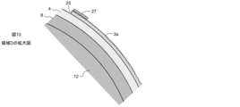
- FIG. 7 is a cross-sectional view illustrating a state where the resin composition having a reverse pattern is transferred to the transfer roll, following FIG. 6. It is an enlarged view of the area
- FIG. 9 is a cross-sectional view showing a state after the resin composition having a reverse pattern has been transferred over the entire circumference of the transfer roll, following FIG. 8. It is an enlarged view of the area
- the imprint mold manufacturing method of the present embodiment includes a resin application step of applying a light or thermosetting resin composition 25 on a pattern transfer mold 2 having a fine uneven pattern 3, and a resin composition 25.
- An apparatus for carrying out this method is not particularly limited, and can be implemented using, for example, an imprint apparatus for imprinting a concavo-convex pattern onto a transfer material as shown in FIG.
- the transfer roll 12 includes an upstream roll 14 that is disposed on the upstream side of the transfer roll 12 and sandwiches the transport film F between the transfer roll 12 and a downstream roll 16 that is disposed on the downstream side of the transfer roll.
- a delivery roll (not shown) for delivering the transport film F is disposed further upstream of the upstream roll 14, and a take-up roll (not illustrated) for winding the transport film F is disposed further downstream of the downstream roll 16.
- a take-up roll not illustrated
- a coater eg, a die coater 18 for applying a transfer material such as a photo-curing resin on the transport film F is installed between the feed roll and the upstream roll 14, and below the transfer roll 12.
- a light irradiator eg, UV light
- Easy Adhesion Treatment Step First it is preferable to include an easy adhesion treatment step for performing an easy adhesion treatment on the transfer roll 12.
- the easy adhesion treatment is a treatment for increasing the affinity between the transfer roll 12 and the resin composition 25 so that the resin composition 25 is easily transferred to the transfer roll 12 in a transfer step described later.
- the implementation method of this process is not specifically limited, It is preferable to implement by winding the easily bonding film 4 around the transfer roll 12.
- the easy-adhesion film 4 only needs to have a high affinity with the resin composition 25, and includes, for example, polyethylene terephthalate, polycarbonate, polyester, polyolefin, polyimide, polysulfone, polyethersulfone, cyclic polyolefin, and polyethylene naphthalate.
- An easy-adhesion layer is formed on at least one surface of a film selected from the group.
- the easy adhesion layer is formed from an acrylic resin, a urethane resin, a polyester resin, and a mixture of these resins.
- a crosslinking agent and a silane coupling agent can be contained in an easily bonding layer.
- the length of the easy-adhesive film 4 may be approximately the same as the outer peripheral length of the transfer roll 12 around which the easy-adhesive film 4 is wound, but is preferably slightly shortened. In this case, with the easy-adhesive film 4 wound around the transfer roll 12, a gap G is naturally formed between the butt portions at both ends of the easy-adhesive film 4, and the resin composition 25 is filled into the gap G. The butted portions at both ends of the easy-adhesive film 4 can be firmly bonded.
- one side of the double-sided pressure-sensitive adhesive tape 8 with the separator 10 is attached to one side of the easy-adhesive film 4.
- the configuration of the double-sided pressure-sensitive adhesive tape 8 is not particularly limited as long as the easy-adhesive film 4 can be attached to the transfer roll 12, but the surface to be attached to the easy-adhesive film 4 (hereinafter referred to as “film adhesive surface”). ) Is stronger than the adhesive force of the surface (hereinafter referred to as “roll adhesive surface”) to be attached to the transfer roll 12, and the roll adhesive surface is preferably removable.
- the double-sided adhesive tape 8 and the easy-adhesive film 4 are peeled together. Therefore, it is preferable that the adhesive strength of the double-sided pressure-sensitive adhesive tape 8 is as strong as possible in order to prevent the double-sided pressure-sensitive adhesive tape 8 and the easy-adhesive film 4 from shifting.
- roll bonding surface of the double-sided adhesive tape 8 to facilitate the peeling from the transfer roll 12 after use, it is preferred to have removability while having the adhesive force of an extent no problem in use.
- the position of the edge part of the winding direction of the double-sided adhesive tape 8 and the easily-adhesive film 4 may correspond, it is preferable that it has shifted
- the positions of the butt portions at both ends of the double-sided pressure-sensitive adhesive tape 8 and the butt portions at both ends of the easy-adhesive film 4 are shifted.
- the resin composition 25 filled in the butted portions at both ends of the easy-adhesive film 4 is filled in portions other than the butted portions of the double-sided pressure-sensitive adhesive tape 8 and prevents the resin composition 25 from adhering to the transfer roll 12. be able to.
- the length of the double-sided pressure-sensitive adhesive tape 8 is preferably substantially equal to the outer peripheral length of the transfer roll 12. In this case, it is because the double-sided adhesive tape 8 is stuck without a gap over the entire circumference of the transfer roll 12. Therefore, when the length of the easy-adhesive film 4 is slightly shorter than the outer peripheral length of the transfer roll 12, the double-sided adhesive tape 8 is slightly longer than the easy-adhesive film 4.
- the structure of the separator 10 is not particularly limited as long as the separator 10 protects the adhesive layer on the roll sticking surface of the double-sided adhesive tape 8 and can be easily peeled when wound around the transfer roll 12.
- the easy-adhesive film 4 to which the double-sided pressure-sensitive adhesive tape 8 with the separator 10 is attached is disposed on the tangent line of the transfer roll 12, and the separator 10 is peeled off in the direction of the arrow Y.
- the easy-adhesion film 4 with the double-sided adhesive tape 8 is inserted between the transport film F and the transfer roll 12.
- each roll rotates in the direction of the arrow shown in each roll, and the easy-adhesive film 4 with the double-sided adhesive tape 8 is pressed against the transfer roll 12 by the upstream side roll 14, and the roll of the double-sided adhesive tape 8.
- the sticking surface is stuck on the transfer roll 12.
- FIG. 3 is an enlarged view of a region A in FIG.
- the double-sided pressure-sensitive adhesive tape 8 is attached to the entire circumference of the transfer roll 12, and the butt portions 8a at both ends are substantially free of gaps. However, there is no problem even if there is a slight gap.
- a gap G is preferably present at the abutting portions at both ends of the easy-adhesive film 4.
- the length of the gap G (the length of the roll in the circumferential direction is referred to as “length”, and the length of the roll in the rotation axis direction is referred to as “width”) is not particularly limited, but may be, for example, 0.1 to 2 mm, preferably 0.2 to 1 mm. This is because the presence of the gap G causes the resin composition 25 to flow into the gap G in a later step, thereby firmly bonding both ends of the easy-adhesive film 4.
- the easy adhesion treatment process may be performed before the resin coating process, or may be performed between the resin coating process and the transfer process.
- a light or thermosetting resin composition 25 is applied onto the pattern transfer mold 2 having the fine uneven pattern 3.
- the pattern transfer mold 2 can be formed by a known imprint technique.
- a resin layer 6 having a desired fine uneven pattern 3 is formed on a flexible resin substrate 5 as shown in FIG. Prepare.
- the resin substrate 5 is made of, for example, one selected from the group consisting of polyethylene terephthalate, polycarbonate, polyester, polyolefin, polyimide, polysulfone, polyethersulfone, cyclic polyolefin, and polyethylene naphthalate.
- the thickness of the resin substrate 5 is usually 6 to 188 ⁇ m, preferably 12 to 100 ⁇ m. With such a thickness, it is easy to apply a uniform pressure in the width direction of the transfer roll 12 during the transfer process described later, and as a result, the resin composition 25 can be uniformly transferred to the transfer roll 12. .
- the resin forming the resin layer 6 may be any of a thermoplastic resin, a thermosetting resin, or a photocurable resin.
- the resin include acrylic resins, styrene resins, olefin resins, polycarbonate resins, polyester resins, epoxy resins, and silicone resins.
- the thickness of the resin layer 6 is usually 50 nm to 1 mm, preferably 500 nm to 500 ⁇ m. With such a thickness, imprinting is easy to perform.
- the mold for forming the concavo-convex pattern is pressed with a press thickness of 0.5 to 50 MPa while the resin layer 6 is heated to a temperature equal to or higher than the glass transition temperature (Tg). After holding and pressing for 10 to 600 seconds, the resin layer 6 is cooled to a temperature of Tg or less, and the mold is separated from the resin layer 6, whereby the uneven pattern 3 can be formed on the resin layer 6.
- the resin forming the resin layer 6 is a photocurable resin
- the resin layer 6 is cured with light (UV light, visible light) in a state in which a mold for forming an uneven pattern is pressed against the liquid resin layer 6.
- the concavo-convex pattern 3 can be formed on the resin layer 6 by irradiating the resin layer 6 by irradiating an energy beam capable of curing the resin such as an electron beam, and then separating the mold.
- the light may be irradiated from the resin base material 4 side, and may be irradiated from the mold side when the mold is transparent to the light.
- the resin forming the resin layer 6 is a thermosetting resin
- the resin layer 6 is heated to a curing temperature in a state where a mold for forming an uneven pattern is pressed against the liquid resin layer 6.
- the concavo-convex pattern 3 can be formed on the resin layer 6 by curing 6 and then separating the mold.
- the light may be irradiated from the resin base material 4 side, and may be irradiated from the mold side when the mold is transparent to light.
- the surface shape (uneven pattern 3) of the resin layer 6 is not particularly limited, but preferably has a period of 10 nm to 2 mm and a depth of 10 nm to 500 ⁇ m, more preferably a period of 20 nm to 20 ⁇ m and a depth of 50 nm to 1 ⁇ m. With this setting, it is possible to transfer a sufficient uneven pattern 3 to the transfer body.
- Examples of the surface shape include moth-eye, line, cylinder, monolith, cone, polygonal pyramid, and microlens.
- the surface of the resin layer 6 may be subjected to a peeling treatment for preventing adhesion with the resin composition 25, and the peeling treatment may form a peeling layer (not shown).
- the release agent for forming the release layer (not shown) is preferably a group consisting of a fluorine-based silane coupling agent, a perfluoro compound having an amino group or a carboxyl group, and a perfluoroether compound having an amino group or a carboxyl group. More preferably selected from the group consisting of a fluorine-based silane coupling agent, a single-terminal aminated perfluoro (perfluoroether) compound and a single-terminal carboxylated perfluoro (perfluoroether) compound.
- the thickness of the release layer (not shown) is preferably in the range of 0.5 to 20 nm, more preferably 0.5 to 10 nm, and most preferably 0.5 to 5 nm.
- an additive having a group capable of binding to a release agent as disclosed in WO2012 / 018045 may be added to the resin layer 6. Good.
- silicone resin such as polydimethylsiloxane (PDMS), a copolymer of an acrylic monomer and a silicone monomer, a copolymer of an acrylic monomer and a fluorine monomer, an acrylic resin
- PDMS polydimethylsiloxane
- a release component is contained in the resin layer 6 in that the step of forming a release layer can be omitted thereafter.
- the length of the pattern transfer mold 2 is preferably the same as or slightly longer than the outer peripheral length of the transfer roll 12. This is because the resin composition 25 applied on the pattern transfer mold 2 can be transferred to the entire circumference of the transfer roll 12.
- a double-sided adhesive tape 9 is attached to the pattern transfer mold 2.
- the same resin as the resin base material 5 can be used for the transport film F, a resin different from the resin base material 5 may be used.
- the double-sided pressure-sensitive adhesive tape 9 has a pressure-sensitive adhesive layer that can affix the pattern transfer mold 2 to the transport film F, the configuration thereof is not particularly limited.
- the pressure-sensitive adhesive layer is preferably composed of an acrylic pressure-sensitive adhesive composition from the viewpoints of cost and handling. Although it does not specifically limit as an acrylic adhesive composition, For example, what mix
- the thickness of the pressure-sensitive adhesive layer is usually in the range of 5 to 50 ⁇ m. *
- Such a pattern transfer mold 2 is attached to the transport film F on the upstream side of the coater 18 as shown in FIG.
- the resin composition 25 is discharged from the coater 18 as shown in FIG.
- the resin composition 25 is applied to the surface.
- the uneven pattern 3 is formed on the surface of the pattern transfer mold 2, the inverted pattern 3 a of the uneven pattern 3 is formed on the resin composition 25 applied thereon.
- Resin composition 25 is a heat or photocurable resin.
- the resin include acrylic resin, epoxy resin, and silicone resin. Since it can be easily cured after pattern formation if it is heat or photo-curing, it is easy to handle.
- the resin composition 25 is preferably a resin containing a peeling component (hereinafter abbreviated as “peelable resin”). This is because the use of the peelable resin can prevent the transfer material from adhering during imprinting of the uneven pattern onto the transfer material without forming a release layer after forming the reverse pattern on the resin composition 25.
- release resins include silicone resins such as polydimethylsiloxane (PDMS), copolymers of acrylic monomers and silicone monomers (including macromonomers), acrylic monomers and fluorine monomers (including macromonomers), Copolymers, acrylic polymers and silicone monomers, acrylic polymers and fluorine monomers, etc., including silicone resins, acrylic monomers and silicone monomers (including macromonomers). Polymers are preferred.
- the resin composition 25 is a thermosetting resin
- the resin base material 5, the resin forming the resin layer 6, the transport film F, and the pressure-sensitive adhesive layer constituting the double-sided pressure-sensitive adhesive tape 9 are thermally conductive fillers. Is preferably contained. By containing the thermally conductive filler, the resin composition 25 can be transferred to the transfer roll 12 in a shorter time.
- thermally conductive filler examples include aluminum hydroxide, magnesium hydroxide, calcium carbonate, magnesium carbonate, calcium silicate, magnesium silicate, calcium oxide, magnesium oxide, zinc oxide, aluminum oxide, titanium oxide, crystalline silica, Examples thereof include amorphous silica, titanium oxide, nickel oxide, iron oxide, copper oxide, aluminum nitride, silicon nitride, boron nitride, gallium nitride, carbon black, carbon nanotube, carbon fiber, and diamond.
- the resin composition 25 is a photocurable resin
- the resin base material 5, the resin forming the resin layer 6, the pressure-sensitive adhesive layer constituting the transport film F and the double-sided pressure-sensitive adhesive tape 9 are highly transparent. Is preferably used.
- the total light transmittance in the visible light wavelength region according to JIS K7361 is 85% or more, preferably 90% or more, more preferably 92% or more, and the haze according to JIS K7136 is 3% or less, preferably 1%. It is as follows.
- the resin composition 25 is shortened by the light irradiator 20 described later. It can be cured more uniformly over time.
- the resin composition is further transferred onto the resin composition 25 after the transfer, in the vicinity of the front end of the resin composition 25 transferred to the transfer roll 12 or the terminal portion of the pattern transfer mold 2.
- a shielding material 27 is provided.
- the shielding material 27 has releasability, and even when the resin composition 25 is cured in a state where the uncured resin composition 25 is attached on the shielding material 27, the resin composition 25 is easily removed. can do.
- the shielding material 27 in addition to a release material such as a silicone resin, a fluorine resin, an alkyd resin, a long-chain alkyl compound, and a wax, pigments or dyes with little or no light transmission, plastic films containing these pigments and dyes For example, a film that blocks ultraviolet light transmission such as a polyimide film, a metal film using aluminum, or the like is used. Further, a light shielding film having a nickel thin film formed on the back surface of the transfer mold 2 can be used.
- a release material such as a silicone resin, a fluorine resin, an alkyd resin, a long-chain alkyl compound, and a wax, pigments or dyes with little or no light transmission
- plastic films containing these pigments and dyes For example, a film that blocks ultraviolet light transmission such as a polyimide film, a metal film using aluminum, or the like is used. Further, a light shielding film having a nickel thin film formed on the back surface of the transfer mold 2 can be used
- the resin composition 25 may be a thermosetting resin.
- a heater is installed below the transfer roll 12 in place of the light irradiator 20 so that the thermosetting resin is appropriately heat-cured and transferred to the transfer roll 12.
- the pattern 3a is preferably subjected to the same peeling treatment as that described above.
- a concavo-convex pattern can be continuously formed on the transfer material.
- the transport film F is discharged by rotating a roll of the imprint apparatus shown in FIG. 1 and discharging a transfer material (eg, photocurable resin) from the coater 18 while transporting the transport film F.
- a transfer material eg, photocurable resin
- a transfer material is applied onto the transfer material, and a seamless imprint mold wound around the transfer roll 12 is pressed against the transfer material.
- light for curing the transfer material is applied to the transfer material from the light irradiator 20.
- the transfer material can be cured to continuously form a concavo-convex pattern on the transfer material.
Landscapes
- Engineering & Computer Science (AREA)
- Mechanical Engineering (AREA)
- Shaping Of Tube Ends By Bending Or Straightening (AREA)
- Moulds For Moulding Plastics Or The Like (AREA)
- Exposure Of Semiconductors, Excluding Electron Or Ion Beam Exposure (AREA)
- Manufacturing & Machinery (AREA)
Abstract
Description
前記樹脂組成物を円柱状の転写ロールの全周に渡って転移させると共に前記樹脂組成物を硬化させることによって、前記転写ロールの全周に渡って前記凹凸パターンの反転パターンを形成する転移工程とを備える、インプリント用モールドの製造方法が提供される。
インプリント用モールドが得られる。
好ましくは、前記樹脂組成物は、光硬化性樹脂であり、前記転移工程では、前記樹脂組成物が前記転写ロールに接触している状態で前記樹脂組成物に対して光を照射することによって前記樹脂組成物を硬化させる。
好ましくは、前記樹脂塗布工程では、前記樹脂組成物は、ロール・トゥー・ロール形式で搬送されている搬送フィルム上に載置された前記パターン転移用モールド上に塗布され、前記転移工程では、回転している前記転写ロールに向かって、前記樹脂組成物が塗布された前記パターン転移用モールドが搬送されることによって、前記転写ロールの全周に渡って前記反転パターンが形成される。
好ましくは、前記転移工程の前に前記転写ロールに易接着処理を行う易接着処理工程をさらに備える。
好ましくは、前記易接着処理は、前記転写ロールに易接着フィルムを巻き付ける処理である。
好ましくは、前記易接着フィルムは、両端の突合せ部に隙間が設けられるように巻き付けられ、前記隙間に前記樹脂組成物が充填される。
好ましくは、前記パターン転移用モールドは、樹脂フィルムモールドであり、その表面が剥離処理されている。
好ましくは、前記樹脂組成物は、剥離性樹脂からなる。
好ましくは、前記転移工程の後に、前記樹脂組成物の表面に対して剥離処理を行う。
好ましくは、前記転移工程中に、前記樹脂組成物の先端近傍または前記パターン転移用モールドの終端部に遮蔽材を設ける。
以下、各工程について詳細に説明する。
最初に、転写ロール12に易接着処理を行う易接着処理工程を備えることが好ましい。易接着処理とは、後述する転移工程で樹脂組成物25が転写ロール12に転移しやすくすべく、転写ロール12と樹脂組成物25の間の親和性を高めるための処理である。この工程の実施方法は、特に限定されないが、転写ロール12に易接着フィルム4を巻き付けることによって実施することが好ましい。易接着フィルム4は、樹脂組成物25との親和性が高いものであればよく、例えば、ポリエチレンテレフタレート、ポリカーボネート、ポリエステル、ポリオレフィン、ポリイミド、ポリサルフォン、ポリエーテルサルフォン、環状ポリオレフィンおよびポリエチレンナフタレートからなる群から選ばれる1種からなるフィルムの少なくとも片面に易接着層が形成されたものである。易接着層は、アクリル樹脂、ウレタン樹脂、ポリエステル樹脂、およびこれら樹脂の混合物から形成される。また、易接着層には、架橋剤やシランカップリング剤を含有させることができる。架橋剤としては、イソシアネート化合物、エポキシ化合物、オキサゾリン化合物、メラミン化合物が挙げられる。
易接着フィルム4の長さは、易接着フィルム4を巻き付ける転写ロール12の外周長と同程度であってもよいが、僅かに短くすることが好ましい。この場合、易接着フィルム4を転写ロール12に巻き付けた状態で、易接着フィルム4の両端の突合せ部の間に自然に隙間Gが形成され、この隙間Gに樹脂組成物25を充填することによって、易接着フィルム4の両端の突合せ部を強固に接合することができる。
この工程では、微細な凹凸パターン3を有するパターン転移用モールド2上に光又は熱硬化性の樹脂組成物25を塗布する。
パターン転移用モールド2は、公知のインプリント技術により形成可能であり、一例では、図4に示すようにフレキシブルな樹脂基材5上に、所望とする微細な凹凸パターン3を有する樹脂層6を備える。
また、樹脂層6を形成する樹脂として、ポリジメチルシロキサン(PDMS)などのシリコーン樹脂、アクリル系モノマーとシリコーン系モノマーとの共重合体、アクリル系モノマーとフッ素系モノマーとの共重合体、アクリル系ポリマーにシリコーン系モノマーとの混合物、アクリル系ポリマーとフッ素系モノマーとの混合物を用いる場合など、樹脂層6に剥離成分を含有させると、その後剥離層を形成させる工程を省略できる点で好ましい。
また、樹脂組成物25が熱硬化性樹脂である場合には、樹脂基材5、樹脂層6を形成する樹脂、搬送フィルムFおよび両面粘着テープ9を構成する粘着剤層には熱伝導性フィラーが含有していることが好ましい。熱伝導性フィラーが含有していることにより、より短時間で樹脂組成物25を転写ロール12に転移させることが可能になる。熱伝導性フィラーとしては、たとえば、水酸化アルミニウム、水酸化マグネシウム、炭酸カルシウム、炭酸マグネシウム、ケイ酸カルシウム、ケイ酸マグネシウム、酸化カルシウム、酸化マグネシウム、酸化亜鉛、酸化アルミニウム、酸化チタン、結晶性シリカ、非結晶性シリカ、酸化チタン、酸化ニッケル、酸化鉄、酸化銅、窒化アルミニウム、窒化ケイ素、窒化ホウ素、窒化ガリウム、カーボンブラック、カーボンナノチューブ、カーボンファイバー、ダイヤモンドが挙げられる。
一方、樹脂組成物25が光硬化性樹脂である場合には、樹脂基材5、樹脂層6を形成する樹脂、搬送フィルムFおよび両面粘着テープ9を構成する粘着剤層は透明性が高いものを用いることが好ましい。具体的には、JIS K7361による可視光波長領域における全光線透過率が85%以上、好ましくは90%以上、より好ましくは92%以上であり、JIS K7136によるヘーズが3%以下、好ましくは1%以下である。透明性の高い樹脂基材5、樹脂層6を形成する樹脂、搬送フィルムFおよび両面粘着テープ9を構成する粘着剤層を用いることにより、後述する光照射器20よって樹脂組成物25をより短時間に、より均一に硬化させることができる。
この工程では、樹脂組成物25を円柱状の転写ロール12の全周に渡って転移させると共に樹脂組成物25を硬化させることによって、転写ロール12の全周に渡って凹凸パターン3の反転パターン3aを形成する。
上記工程で樹脂組成物25をパターン転移用モールド2上に塗布した後、搬送フィルムFの搬送を継続すると、図8に示すように、上流側ロール14と転写ロール12の間で、上流側ロール14によって搬送フィルムFが転写ロール12の方向に押し付けられ、それによって、パターン転移用モールド2上の樹脂組成物25が転写ロール12に付着される。搬送フィルムFがさらに搬送されると、パターン転移用モールド2は、転写ロール12の下方に到達し、図9に示すように、その位置で光照射器20によって樹脂組成物25が硬化され、樹脂組成物25上には、凹凸パターン3の反転パターン3aが形成される。そして、搬送フィルムFがさらに搬送されて、下流側ロール14に到達すると、搬送フィルムFは、より下流側に設けられた巻取りロール(図示せず)に引っ張られて図8の矢印Zの方向に移動するのに対し、転写ロール12はそのまま回転方向に移動するので、搬送フィルムFが転写ロール12から分離される。この際に、硬化済みの樹脂組成物25は、より親和性が高い方に接着されるので、転写ロール12への易接着処理と、パターン転移用モールド2への剥離処理のうちの一方又は両方を予め行なって、樹脂組成物25と転写ロール12との親和性が、樹脂組成物25とパターン転移用モールド2との親和性よりも高くなるようにしておく。このようにすることで、反転パターン3aを有する樹脂組成物25が、図10に示すように、転写ロール12に転移される。
Claims (10)
- 微細な凹凸パターンを有するパターン転移用モールド上に光又は熱硬化性の樹脂組成物を塗布する樹脂塗布工程と、
前記樹脂組成物を円柱状の転写ロールの全周に渡って転移させると共に前記樹脂組成物を硬化させることによって、前記転写ロールの全周に渡って前記凹凸パターンの反転パターンを形成する転移工程とを備える、インプリント用モールドの製造方法。 - 前記樹脂組成物は、光硬化性樹脂であり、
前記転移工程では、前記樹脂組成物が前記転写ロールに接触している状態で前記樹脂組成物に対して光を照射することによって前記樹脂組成物を硬化させる、請求項1に記載の製造方法。 - 前記樹脂塗布工程では、前記樹脂組成物は、ロール・トゥー・ロール形式で搬送されている搬送フィルム上に載置された前記パターン転移用モールド上に塗布され、
前記転移工程では、回転している前記転写ロールに向かって、前記樹脂組成物が塗布された前記パターン転移用モールドが搬送されることによって、前記転写ロールの全周に渡って前記反転パターンが形成される、請求項1又は2に記載の製造方法。 - 前記転移工程の前に前記転写ロールに易接着処理を行う易接着処理工程をさらに備える、請求項1~3の何れか1つに記載の製造方法。
- 前記易接着処理は、前記転写ロールに易接着フィルムを巻き付ける処理である、請求項4に記載の製造方法。
- 前記易接着フィルムは、両端の突合せ部に隙間が設けられるように巻き付けられ、前記隙間に前記樹脂組成物が充填される、請求項5に記載の製造方法。
- 前記パターン転移用モールドは、樹脂フィルムモールドであり、その表面が剥離処理されている、請求項1~6の何れか1つに記載の製造方法。
- 前記樹脂組成物は、剥離性樹脂からなる、請求項1~7の何れか1つに記載の製造方法。
- 前記転移工程の後に、前記樹脂組成物の表面に対して剥離処理を行う、請求項1~8の何れか1つに記載の製造方法。
- 前記転移工程中に、前記樹脂組成物の先端近傍または前記パターン転移用モールドの終端部に遮蔽材を設ける、請求項1~9の何れか1つに記載の製造方法。
Priority Applications (5)
| Application Number | Priority Date | Filing Date | Title |
|---|---|---|---|
| DK13856381.2T DK2923818T3 (en) | 2012-11-22 | 2013-11-18 | Process for making an embossing mold |
| JP2014548549A JP6244312B2 (ja) | 2012-11-22 | 2013-11-18 | インプリント用モールドの製造方法 |
| EP13856381.2A EP2923818B1 (en) | 2012-11-22 | 2013-11-18 | Imprint mold manufacturing method |
| CN201380060874.XA CN104853897B (zh) | 2012-11-22 | 2013-11-18 | 压印用模具的制造方法 |
| US14/443,326 US9776359B2 (en) | 2012-11-22 | 2013-11-18 | Imprint mold manufacturing method |
Applications Claiming Priority (2)
| Application Number | Priority Date | Filing Date | Title |
|---|---|---|---|
| JP2012-256556 | 2012-11-22 | ||
| JP2012256556 | 2012-11-22 |
Publications (1)
| Publication Number | Publication Date |
|---|---|
| WO2014080858A1 true WO2014080858A1 (ja) | 2014-05-30 |
Family
ID=50776041
Family Applications (1)
| Application Number | Title | Priority Date | Filing Date |
|---|---|---|---|
| PCT/JP2013/081013 Ceased WO2014080858A1 (ja) | 2012-11-22 | 2013-11-18 | インプリント用モールドの製造方法 |
Country Status (8)
| Country | Link |
|---|---|
| US (1) | US9776359B2 (ja) |
| EP (1) | EP2923818B1 (ja) |
| JP (1) | JP6244312B2 (ja) |
| KR (1) | KR20150086502A (ja) |
| CN (1) | CN104853897B (ja) |
| DK (1) | DK2923818T3 (ja) |
| TW (1) | TWI583526B (ja) |
| WO (1) | WO2014080858A1 (ja) |
Families Citing this family (11)
| Publication number | Priority date | Publication date | Assignee | Title |
|---|---|---|---|---|
| TW201718228A (zh) * | 2015-09-17 | 2017-06-01 | 綜研化學股份有限公司 | 壓印用模具的製造方法 |
| CN105383156A (zh) * | 2015-12-01 | 2016-03-09 | 佛山市三水南基塑胶制品有限公司 | Pu皮纹理转印设备 |
| KR102490286B1 (ko) * | 2016-01-18 | 2023-01-19 | 도레이 카부시키가이샤 | 표면 구조 필름의 제조방법 및 제조장치 |
| US10074626B2 (en) * | 2016-06-06 | 2018-09-11 | Shin-Etsu Chemical Co., Ltd. | Wafer laminate and making method |
| JP6511612B2 (ja) * | 2016-08-15 | 2019-05-15 | 国立研究開発法人宇宙航空研究開発機構 | リブレット用転写シート、リブレット用転写シートの製造方法及びリブレット成形方法 |
| JP7245973B2 (ja) * | 2019-02-04 | 2023-03-27 | パナソニックIpマネジメント株式会社 | パターンの形成方法および装置 |
| EP3895867B1 (en) * | 2020-04-14 | 2025-06-18 | Essilor International | Method for generating microstructure on a film by a roller |
| CN111452272A (zh) * | 2020-04-14 | 2020-07-28 | 佛山市三乐建材实业有限公司 | 一种板材模具成型筒的制作方法及使用该筒转印的木纹板 |
| CN111497430B (zh) * | 2020-04-27 | 2021-04-02 | 中冶京诚工程技术有限公司 | 多辊式连续高速转印机 |
| EP4354222A1 (en) * | 2022-10-11 | 2024-04-17 | Max-Planck-Gesellschaft zur Förderung der Wissenschaften e.V. | Method of roll-to-roll (r2r) manufacturing of a 3d-patterned microstructure, use of a 3d-patterned microstructure, and an apparatus for manufacturing a 3d-patterned microstructure |
| KR20250046030A (ko) * | 2023-09-26 | 2025-04-02 | 삼성전자주식회사 | 금형의 표면 코팅에 사용되는 코팅액 및 금형의 표면 코팅 방법 |
Citations (8)
| Publication number | Priority date | Publication date | Assignee | Title |
|---|---|---|---|---|
| JPH03235233A (ja) * | 1990-02-09 | 1991-10-21 | Canon Inc | 情報記録媒体用基板の成形用ロール型の製造方法及びそれを用いた情報記録媒体用基板の製造方法 |
| JPH0724914A (ja) * | 1993-07-12 | 1995-01-27 | Toppan Printing Co Ltd | エンボス版の製造方法 |
| JP2003181918A (ja) * | 2001-12-19 | 2003-07-03 | Dainippon Printing Co Ltd | 賦型用ローラ、賦型された表面を有する積層フィルムの製造方法、および賦型された積層フィルム |
| JP2006064455A (ja) * | 2004-08-25 | 2006-03-09 | Isamu Ko | 基準格子製造方法及び基準格子製造装置 |
| JP2010149492A (ja) * | 2008-11-20 | 2010-07-08 | Toppan Printing Co Ltd | 光学シートの製造方法および光学シート |
| JP2011083984A (ja) * | 2009-10-16 | 2011-04-28 | Seiko Epson Corp | ロール型の製造方法 |
| WO2011049097A1 (ja) | 2009-10-21 | 2011-04-28 | 旭硝子株式会社 | インプリント用モールド、その製造方法、インプリント装置およびインプリント方法 |
| WO2012018045A1 (ja) | 2010-08-06 | 2012-02-09 | 綜研化学株式会社 | 樹脂製モールド、その製造方法およびその使用方法 |
Family Cites Families (6)
| Publication number | Priority date | Publication date | Assignee | Title |
|---|---|---|---|---|
| US8027086B2 (en) * | 2007-04-10 | 2011-09-27 | The Regents Of The University Of Michigan | Roll to roll nanoimprint lithography |
| JP4469385B2 (ja) | 2007-05-31 | 2010-05-26 | 株式会社日立産機システム | 微細モールド及びその製造方法 |
| CN102152441A (zh) * | 2010-02-12 | 2011-08-17 | 徽达科技股份有限公司 | 软性模具与制作方法及模内装饰材料和注塑外观件 |
| KR101726625B1 (ko) * | 2010-08-13 | 2017-04-14 | 엘지디스플레이 주식회사 | 롤 몰드, 그 제조 방법 및 장치와 그를 이용한 박막 패턴의 제조 방법 |
| US20120135191A1 (en) * | 2010-11-30 | 2012-05-31 | Lora Lee Spangler | Systems, Methods and Apparatuses for Direct Embossment of a Polymer Melt Sheet |
| KR101333534B1 (ko) * | 2011-03-22 | 2013-11-28 | (주)뉴옵틱스 | Uv 임프린트 기법을 이용하여 원통 금형에 패턴을 복제하는 방법 |
-
2013
- 2013-11-18 DK DK13856381.2T patent/DK2923818T3/en active
- 2013-11-18 US US14/443,326 patent/US9776359B2/en not_active Expired - Fee Related
- 2013-11-18 CN CN201380060874.XA patent/CN104853897B/zh not_active Expired - Fee Related
- 2013-11-18 WO PCT/JP2013/081013 patent/WO2014080858A1/ja not_active Ceased
- 2013-11-18 JP JP2014548549A patent/JP6244312B2/ja not_active Expired - Fee Related
- 2013-11-18 EP EP13856381.2A patent/EP2923818B1/en not_active Not-in-force
- 2013-11-18 KR KR1020157015957A patent/KR20150086502A/ko not_active Ceased
- 2013-11-20 TW TW102142179A patent/TWI583526B/zh not_active IP Right Cessation
Patent Citations (8)
| Publication number | Priority date | Publication date | Assignee | Title |
|---|---|---|---|---|
| JPH03235233A (ja) * | 1990-02-09 | 1991-10-21 | Canon Inc | 情報記録媒体用基板の成形用ロール型の製造方法及びそれを用いた情報記録媒体用基板の製造方法 |
| JPH0724914A (ja) * | 1993-07-12 | 1995-01-27 | Toppan Printing Co Ltd | エンボス版の製造方法 |
| JP2003181918A (ja) * | 2001-12-19 | 2003-07-03 | Dainippon Printing Co Ltd | 賦型用ローラ、賦型された表面を有する積層フィルムの製造方法、および賦型された積層フィルム |
| JP2006064455A (ja) * | 2004-08-25 | 2006-03-09 | Isamu Ko | 基準格子製造方法及び基準格子製造装置 |
| JP2010149492A (ja) * | 2008-11-20 | 2010-07-08 | Toppan Printing Co Ltd | 光学シートの製造方法および光学シート |
| JP2011083984A (ja) * | 2009-10-16 | 2011-04-28 | Seiko Epson Corp | ロール型の製造方法 |
| WO2011049097A1 (ja) | 2009-10-21 | 2011-04-28 | 旭硝子株式会社 | インプリント用モールド、その製造方法、インプリント装置およびインプリント方法 |
| WO2012018045A1 (ja) | 2010-08-06 | 2012-02-09 | 綜研化学株式会社 | 樹脂製モールド、その製造方法およびその使用方法 |
Non-Patent Citations (1)
| Title |
|---|
| See also references of EP2923818A4 |
Also Published As
| Publication number | Publication date |
|---|---|
| EP2923818B1 (en) | 2018-07-18 |
| US9776359B2 (en) | 2017-10-03 |
| EP2923818A1 (en) | 2015-09-30 |
| KR20150086502A (ko) | 2015-07-28 |
| TW201429666A (zh) | 2014-08-01 |
| DK2923818T3 (en) | 2018-10-22 |
| CN104853897A (zh) | 2015-08-19 |
| TWI583526B (zh) | 2017-05-21 |
| EP2923818A4 (en) | 2016-09-28 |
| JP6244312B2 (ja) | 2017-12-06 |
| US20150336324A1 (en) | 2015-11-26 |
| JPWO2014080858A1 (ja) | 2017-01-05 |
| CN104853897B (zh) | 2017-05-03 |
Similar Documents
| Publication | Publication Date | Title |
|---|---|---|
| JP6244312B2 (ja) | インプリント用モールドの製造方法 | |
| JP6275048B2 (ja) | インプリント用モールドの製造方法、インプリント用モールド、インプリント用モールド製造キット | |
| JP5768133B2 (ja) | 樹脂製モールドの接合方法およびこの接合方法で製造されたロールトゥーロール用連続モールド構成体 | |
| TWI698320B (zh) | 表面構造薄膜之製造方法及製造裝置 | |
| CN107533958A (zh) | 凹凸图案形成体的制造方法、其制造装置以及贴纸 | |
| CN108025484B (zh) | 压印用模具的制造方法 | |
| CN107405824A (zh) | 凹凸图案形成体的制造方法和压印装置 | |
| US9855703B2 (en) | Method of forming aligned pattern in pattern formation region by using imprint process | |
| JP2016094587A (ja) | 接着剤及び基板の製造方法並びに基板保持シート | |
| JP2005011877A (ja) | 回路パターン形成方法 | |
| JP4793010B2 (ja) | 光回折構造賦型用の複製版及びその複製版の製造方法並びに複製版を用いた光回折構造転写用複製物の製造方法 | |
| JP7471065B2 (ja) | スリーブ印刷版およびその製造方法 | |
| JP2009224005A (ja) | 光情報記録媒体の製造方法及びそれに用いられるスタンパ基板 |
Legal Events
| Date | Code | Title | Description |
|---|---|---|---|
| 121 | Ep: the epo has been informed by wipo that ep was designated in this application |
Ref document number: 13856381 Country of ref document: EP Kind code of ref document: A1 |
|
| ENP | Entry into the national phase |
Ref document number: 2014548549 Country of ref document: JP Kind code of ref document: A |
|
| WWE | Wipo information: entry into national phase |
Ref document number: 14443326 Country of ref document: US |
|
| NENP | Non-entry into the national phase |
Ref country code: DE |
|
| WWE | Wipo information: entry into national phase |
Ref document number: 2013856381 Country of ref document: EP |
|
| ENP | Entry into the national phase |
Ref document number: 20157015957 Country of ref document: KR Kind code of ref document: A |