WO2014087580A1 - Dispositif de gestion de charge/décharge, système de conditionnement d'énergie, dispositif de stockage d'énergie, et programme - Google Patents
Dispositif de gestion de charge/décharge, système de conditionnement d'énergie, dispositif de stockage d'énergie, et programme Download PDFInfo
- Publication number
- WO2014087580A1 WO2014087580A1 PCT/JP2013/006665 JP2013006665W WO2014087580A1 WO 2014087580 A1 WO2014087580 A1 WO 2014087580A1 JP 2013006665 W JP2013006665 W JP 2013006665W WO 2014087580 A1 WO2014087580 A1 WO 2014087580A1
- Authority
- WO
- WIPO (PCT)
- Prior art keywords
- storage battery
- power
- charge
- unit
- discharge
- Prior art date
- Legal status (The legal status is an assumption and is not a legal conclusion. Google has not performed a legal analysis and makes no representation as to the accuracy of the status listed.)
- Ceased
Links
Images



Classifications
-
- H—ELECTRICITY
- H02—GENERATION; CONVERSION OR DISTRIBUTION OF ELECTRIC POWER
- H02J—ELECTRIC POWER NETWORKS; CIRCUIT ARRANGEMENTS OR SYSTEMS FOR SUPPLYING OR DISTRIBUTING ELECTRIC POWER; SYSTEMS FOR STORING ELECTRIC ENERGY
- H02J7/00—Circuit arrangements for charging or discharging batteries or for supplying loads from batteries
- H02J7/90—Regulation of charging or discharging current or voltage
- H02J7/971—Regulation of charging or discharging current or voltage the charge cycle being controlled or terminated in response to non-electric parameters
- H02J7/975—Regulation of charging or discharging current or voltage the charge cycle being controlled or terminated in response to non-electric parameters in response to temperature
- H02J7/977—Regulation of charging or discharging current or voltage the charge cycle being controlled or terminated in response to non-electric parameters in response to temperature of the battery
-
- B—PERFORMING OPERATIONS; TRANSPORTING
- B60—VEHICLES IN GENERAL
- B60L—PROPULSION OF ELECTRICALLY-PROPELLED VEHICLES; SUPPLYING ELECTRIC POWER FOR AUXILIARY EQUIPMENT OF ELECTRICALLY-PROPELLED VEHICLES; ELECTRODYNAMIC BRAKE SYSTEMS FOR VEHICLES IN GENERAL; MAGNETIC SUSPENSION OR LEVITATION FOR VEHICLES; MONITORING OPERATING VARIABLES OF ELECTRICALLY-PROPELLED VEHICLES; ELECTRIC SAFETY DEVICES FOR ELECTRICALLY-PROPELLED VEHICLES
- B60L3/00—Electric devices on electrically-propelled vehicles for safety purposes; Monitoring operating variables, e.g. speed, deceleration or energy consumption
- B60L3/0023—Detecting, eliminating, remedying or compensating for drive train abnormalities, e.g. failures within the drive train
- B60L3/0046—Detecting, eliminating, remedying or compensating for drive train abnormalities, e.g. failures within the drive train relating to electric energy storage systems, e.g. batteries or capacitors
-
- B—PERFORMING OPERATIONS; TRANSPORTING
- B60—VEHICLES IN GENERAL
- B60L—PROPULSION OF ELECTRICALLY-PROPELLED VEHICLES; SUPPLYING ELECTRIC POWER FOR AUXILIARY EQUIPMENT OF ELECTRICALLY-PROPELLED VEHICLES; ELECTRODYNAMIC BRAKE SYSTEMS FOR VEHICLES IN GENERAL; MAGNETIC SUSPENSION OR LEVITATION FOR VEHICLES; MONITORING OPERATING VARIABLES OF ELECTRICALLY-PROPELLED VEHICLES; ELECTRIC SAFETY DEVICES FOR ELECTRICALLY-PROPELLED VEHICLES
- B60L53/00—Methods of charging batteries, specially adapted for electric vehicles; Charging stations or on-board charging equipment therefor; Exchange of energy storage elements in electric vehicles
- B60L53/10—Methods of charging batteries, specially adapted for electric vehicles; Charging stations or on-board charging equipment therefor; Exchange of energy storage elements in electric vehicles characterised by the energy transfer between the charging station and the vehicle
- B60L53/14—Conductive energy transfer
-
- B—PERFORMING OPERATIONS; TRANSPORTING
- B60—VEHICLES IN GENERAL
- B60L—PROPULSION OF ELECTRICALLY-PROPELLED VEHICLES; SUPPLYING ELECTRIC POWER FOR AUXILIARY EQUIPMENT OF ELECTRICALLY-PROPELLED VEHICLES; ELECTRODYNAMIC BRAKE SYSTEMS FOR VEHICLES IN GENERAL; MAGNETIC SUSPENSION OR LEVITATION FOR VEHICLES; MONITORING OPERATING VARIABLES OF ELECTRICALLY-PROPELLED VEHICLES; ELECTRIC SAFETY DEVICES FOR ELECTRICALLY-PROPELLED VEHICLES
- B60L53/00—Methods of charging batteries, specially adapted for electric vehicles; Charging stations or on-board charging equipment therefor; Exchange of energy storage elements in electric vehicles
- B60L53/20—Methods of charging batteries, specially adapted for electric vehicles; Charging stations or on-board charging equipment therefor; Exchange of energy storage elements in electric vehicles characterised by converters located in the vehicle
- B60L53/22—Constructional details or arrangements of charging converters specially adapted for charging electric vehicles
-
- B—PERFORMING OPERATIONS; TRANSPORTING
- B60—VEHICLES IN GENERAL
- B60L—PROPULSION OF ELECTRICALLY-PROPELLED VEHICLES; SUPPLYING ELECTRIC POWER FOR AUXILIARY EQUIPMENT OF ELECTRICALLY-PROPELLED VEHICLES; ELECTRODYNAMIC BRAKE SYSTEMS FOR VEHICLES IN GENERAL; MAGNETIC SUSPENSION OR LEVITATION FOR VEHICLES; MONITORING OPERATING VARIABLES OF ELECTRICALLY-PROPELLED VEHICLES; ELECTRIC SAFETY DEVICES FOR ELECTRICALLY-PROPELLED VEHICLES
- B60L53/00—Methods of charging batteries, specially adapted for electric vehicles; Charging stations or on-board charging equipment therefor; Exchange of energy storage elements in electric vehicles
- B60L53/30—Constructional details of charging stations
- B60L53/305—Communication interfaces
-
- B—PERFORMING OPERATIONS; TRANSPORTING
- B60—VEHICLES IN GENERAL
- B60L—PROPULSION OF ELECTRICALLY-PROPELLED VEHICLES; SUPPLYING ELECTRIC POWER FOR AUXILIARY EQUIPMENT OF ELECTRICALLY-PROPELLED VEHICLES; ELECTRODYNAMIC BRAKE SYSTEMS FOR VEHICLES IN GENERAL; MAGNETIC SUSPENSION OR LEVITATION FOR VEHICLES; MONITORING OPERATING VARIABLES OF ELECTRICALLY-PROPELLED VEHICLES; ELECTRIC SAFETY DEVICES FOR ELECTRICALLY-PROPELLED VEHICLES
- B60L53/00—Methods of charging batteries, specially adapted for electric vehicles; Charging stations or on-board charging equipment therefor; Exchange of energy storage elements in electric vehicles
- B60L53/60—Monitoring or controlling charging stations
- B60L53/62—Monitoring or controlling charging stations in response to charging parameters, e.g. current, voltage or electrical charge
-
- B—PERFORMING OPERATIONS; TRANSPORTING
- B60—VEHICLES IN GENERAL
- B60L—PROPULSION OF ELECTRICALLY-PROPELLED VEHICLES; SUPPLYING ELECTRIC POWER FOR AUXILIARY EQUIPMENT OF ELECTRICALLY-PROPELLED VEHICLES; ELECTRODYNAMIC BRAKE SYSTEMS FOR VEHICLES IN GENERAL; MAGNETIC SUSPENSION OR LEVITATION FOR VEHICLES; MONITORING OPERATING VARIABLES OF ELECTRICALLY-PROPELLED VEHICLES; ELECTRIC SAFETY DEVICES FOR ELECTRICALLY-PROPELLED VEHICLES
- B60L55/00—Arrangements for supplying energy stored within a vehicle to a power network, i.e. vehicle-to-grid [V2G] arrangements
-
- B—PERFORMING OPERATIONS; TRANSPORTING
- B60—VEHICLES IN GENERAL
- B60L—PROPULSION OF ELECTRICALLY-PROPELLED VEHICLES; SUPPLYING ELECTRIC POWER FOR AUXILIARY EQUIPMENT OF ELECTRICALLY-PROPELLED VEHICLES; ELECTRODYNAMIC BRAKE SYSTEMS FOR VEHICLES IN GENERAL; MAGNETIC SUSPENSION OR LEVITATION FOR VEHICLES; MONITORING OPERATING VARIABLES OF ELECTRICALLY-PROPELLED VEHICLES; ELECTRIC SAFETY DEVICES FOR ELECTRICALLY-PROPELLED VEHICLES
- B60L58/00—Methods or circuit arrangements for monitoring or controlling batteries or fuel cells, specially adapted for electric vehicles
- B60L58/10—Methods or circuit arrangements for monitoring or controlling batteries or fuel cells, specially adapted for electric vehicles for monitoring or controlling batteries
- B60L58/12—Methods or circuit arrangements for monitoring or controlling batteries or fuel cells, specially adapted for electric vehicles for monitoring or controlling batteries responding to state of charge [SoC]
- B60L58/14—Preventing excessive discharging
-
- B—PERFORMING OPERATIONS; TRANSPORTING
- B60—VEHICLES IN GENERAL
- B60L—PROPULSION OF ELECTRICALLY-PROPELLED VEHICLES; SUPPLYING ELECTRIC POWER FOR AUXILIARY EQUIPMENT OF ELECTRICALLY-PROPELLED VEHICLES; ELECTRODYNAMIC BRAKE SYSTEMS FOR VEHICLES IN GENERAL; MAGNETIC SUSPENSION OR LEVITATION FOR VEHICLES; MONITORING OPERATING VARIABLES OF ELECTRICALLY-PROPELLED VEHICLES; ELECTRIC SAFETY DEVICES FOR ELECTRICALLY-PROPELLED VEHICLES
- B60L58/00—Methods or circuit arrangements for monitoring or controlling batteries or fuel cells, specially adapted for electric vehicles
- B60L58/10—Methods or circuit arrangements for monitoring or controlling batteries or fuel cells, specially adapted for electric vehicles for monitoring or controlling batteries
- B60L58/16—Methods or circuit arrangements for monitoring or controlling batteries or fuel cells, specially adapted for electric vehicles for monitoring or controlling batteries responding to battery ageing, e.g. to the number of charging cycles or the state of health [SoH]
-
- B—PERFORMING OPERATIONS; TRANSPORTING
- B60—VEHICLES IN GENERAL
- B60L—PROPULSION OF ELECTRICALLY-PROPELLED VEHICLES; SUPPLYING ELECTRIC POWER FOR AUXILIARY EQUIPMENT OF ELECTRICALLY-PROPELLED VEHICLES; ELECTRODYNAMIC BRAKE SYSTEMS FOR VEHICLES IN GENERAL; MAGNETIC SUSPENSION OR LEVITATION FOR VEHICLES; MONITORING OPERATING VARIABLES OF ELECTRICALLY-PROPELLED VEHICLES; ELECTRIC SAFETY DEVICES FOR ELECTRICALLY-PROPELLED VEHICLES
- B60L58/00—Methods or circuit arrangements for monitoring or controlling batteries or fuel cells, specially adapted for electric vehicles
- B60L58/10—Methods or circuit arrangements for monitoring or controlling batteries or fuel cells, specially adapted for electric vehicles for monitoring or controlling batteries
- B60L58/24—Methods or circuit arrangements for monitoring or controlling batteries or fuel cells, specially adapted for electric vehicles for monitoring or controlling batteries for controlling the temperature of batteries
-
- B—PERFORMING OPERATIONS; TRANSPORTING
- B60—VEHICLES IN GENERAL
- B60L—PROPULSION OF ELECTRICALLY-PROPELLED VEHICLES; SUPPLYING ELECTRIC POWER FOR AUXILIARY EQUIPMENT OF ELECTRICALLY-PROPELLED VEHICLES; ELECTRODYNAMIC BRAKE SYSTEMS FOR VEHICLES IN GENERAL; MAGNETIC SUSPENSION OR LEVITATION FOR VEHICLES; MONITORING OPERATING VARIABLES OF ELECTRICALLY-PROPELLED VEHICLES; ELECTRIC SAFETY DEVICES FOR ELECTRICALLY-PROPELLED VEHICLES
- B60L58/00—Methods or circuit arrangements for monitoring or controlling batteries or fuel cells, specially adapted for electric vehicles
- B60L58/10—Methods or circuit arrangements for monitoring or controlling batteries or fuel cells, specially adapted for electric vehicles for monitoring or controlling batteries
- B60L58/24—Methods or circuit arrangements for monitoring or controlling batteries or fuel cells, specially adapted for electric vehicles for monitoring or controlling batteries for controlling the temperature of batteries
- B60L58/25—Methods or circuit arrangements for monitoring or controlling batteries or fuel cells, specially adapted for electric vehicles for monitoring or controlling batteries for controlling the temperature of batteries by controlling the electric load
-
- H—ELECTRICITY
- H01—ELECTRIC ELEMENTS
- H01M—PROCESSES OR MEANS, e.g. BATTERIES, FOR THE DIRECT CONVERSION OF CHEMICAL ENERGY INTO ELECTRICAL ENERGY
- H01M10/00—Secondary cells; Manufacture thereof
- H01M10/42—Methods or arrangements for servicing or maintenance of secondary cells or secondary half-cells
- H01M10/44—Methods for charging or discharging
- H01M10/443—Methods for charging or discharging in response to temperature
-
- H—ELECTRICITY
- H01—ELECTRIC ELEMENTS
- H01M—PROCESSES OR MEANS, e.g. BATTERIES, FOR THE DIRECT CONVERSION OF CHEMICAL ENERGY INTO ELECTRICAL ENERGY
- H01M10/00—Secondary cells; Manufacture thereof
- H01M10/42—Methods or arrangements for servicing or maintenance of secondary cells or secondary half-cells
- H01M10/48—Accumulators combined with arrangements for measuring, testing or indicating the condition of cells, e.g. the level or density of the electrolyte
-
- H—ELECTRICITY
- H01—ELECTRIC ELEMENTS
- H01M—PROCESSES OR MEANS, e.g. BATTERIES, FOR THE DIRECT CONVERSION OF CHEMICAL ENERGY INTO ELECTRICAL ENERGY
- H01M10/00—Secondary cells; Manufacture thereof
- H01M10/42—Methods or arrangements for servicing or maintenance of secondary cells or secondary half-cells
- H01M10/48—Accumulators combined with arrangements for measuring, testing or indicating the condition of cells, e.g. the level or density of the electrolyte
- H01M10/486—Accumulators combined with arrangements for measuring, testing or indicating the condition of cells, e.g. the level or density of the electrolyte for measuring temperature
-
- H—ELECTRICITY
- H01—ELECTRIC ELEMENTS
- H01M—PROCESSES OR MEANS, e.g. BATTERIES, FOR THE DIRECT CONVERSION OF CHEMICAL ENERGY INTO ELECTRICAL ENERGY
- H01M10/00—Secondary cells; Manufacture thereof
- H01M10/42—Methods or arrangements for servicing or maintenance of secondary cells or secondary half-cells
- H01M10/48—Accumulators combined with arrangements for measuring, testing or indicating the condition of cells, e.g. the level or density of the electrolyte
- H01M10/488—Cells or batteries combined with indicating means for external visualization of the condition, e.g. by change of colour or of light density
-
- H—ELECTRICITY
- H01—ELECTRIC ELEMENTS
- H01M—PROCESSES OR MEANS, e.g. BATTERIES, FOR THE DIRECT CONVERSION OF CHEMICAL ENERGY INTO ELECTRICAL ENERGY
- H01M50/00—Constructional details or processes of manufacture of the non-active parts of electrochemical cells other than fuel cells, e.g. hybrid cells
- H01M50/50—Current conducting connections for cells or batteries
- H01M50/569—Constructional details of current conducting connections for detecting conditions inside cells or batteries, e.g. details of voltage sensing terminals
-
- H—ELECTRICITY
- H02—GENERATION; CONVERSION OR DISTRIBUTION OF ELECTRIC POWER
- H02J—ELECTRIC POWER NETWORKS; CIRCUIT ARRANGEMENTS OR SYSTEMS FOR SUPPLYING OR DISTRIBUTING ELECTRIC POWER; SYSTEMS FOR STORING ELECTRIC ENERGY
- H02J7/00—Circuit arrangements for charging or discharging batteries or for supplying loads from batteries
- H02J7/02—Circuit arrangements for charging or discharging batteries or for supplying loads from batteries for charging batteries from AC mains by converters
- H02J7/04—Regulation of charging current or voltage
-
- H—ELECTRICITY
- H02—GENERATION; CONVERSION OR DISTRIBUTION OF ELECTRIC POWER
- H02J—ELECTRIC POWER NETWORKS; CIRCUIT ARRANGEMENTS OR SYSTEMS FOR SUPPLYING OR DISTRIBUTING ELECTRIC POWER; SYSTEMS FOR STORING ELECTRIC ENERGY
- H02J7/00—Circuit arrangements for charging or discharging batteries or for supplying loads from batteries
- H02J7/80—Circuit arrangements for charging or discharging batteries or for supplying loads from batteries including monitoring or indicating arrangements
-
- H—ELECTRICITY
- H02—GENERATION; CONVERSION OR DISTRIBUTION OF ELECTRIC POWER
- H02J—ELECTRIC POWER NETWORKS; CIRCUIT ARRANGEMENTS OR SYSTEMS FOR SUPPLYING OR DISTRIBUTING ELECTRIC POWER; SYSTEMS FOR STORING ELECTRIC ENERGY
- H02J7/00—Circuit arrangements for charging or discharging batteries or for supplying loads from batteries
- H02J7/80—Circuit arrangements for charging or discharging batteries or for supplying loads from batteries including monitoring or indicating arrangements
- H02J7/84—Control of state of health [SOH]
-
- H—ELECTRICITY
- H02—GENERATION; CONVERSION OR DISTRIBUTION OF ELECTRIC POWER
- H02J—ELECTRIC POWER NETWORKS; CIRCUIT ARRANGEMENTS OR SYSTEMS FOR SUPPLYING OR DISTRIBUTING ELECTRIC POWER; SYSTEMS FOR STORING ELECTRIC ENERGY
- H02J7/00—Circuit arrangements for charging or discharging batteries or for supplying loads from batteries
- H02J7/855—Circuit arrangements for charging or discharging batteries or for supplying loads from batteries with circuits adapted for supplying loads from the battery
-
- B—PERFORMING OPERATIONS; TRANSPORTING
- B60—VEHICLES IN GENERAL
- B60L—PROPULSION OF ELECTRICALLY-PROPELLED VEHICLES; SUPPLYING ELECTRIC POWER FOR AUXILIARY EQUIPMENT OF ELECTRICALLY-PROPELLED VEHICLES; ELECTRODYNAMIC BRAKE SYSTEMS FOR VEHICLES IN GENERAL; MAGNETIC SUSPENSION OR LEVITATION FOR VEHICLES; MONITORING OPERATING VARIABLES OF ELECTRICALLY-PROPELLED VEHICLES; ELECTRIC SAFETY DEVICES FOR ELECTRICALLY-PROPELLED VEHICLES
- B60L2240/00—Control parameters of input or output; Target parameters
- B60L2240/40—Drive Train control parameters
- B60L2240/54—Drive Train control parameters related to batteries
- B60L2240/545—Temperature
-
- B—PERFORMING OPERATIONS; TRANSPORTING
- B60—VEHICLES IN GENERAL
- B60L—PROPULSION OF ELECTRICALLY-PROPELLED VEHICLES; SUPPLYING ELECTRIC POWER FOR AUXILIARY EQUIPMENT OF ELECTRICALLY-PROPELLED VEHICLES; ELECTRODYNAMIC BRAKE SYSTEMS FOR VEHICLES IN GENERAL; MAGNETIC SUSPENSION OR LEVITATION FOR VEHICLES; MONITORING OPERATING VARIABLES OF ELECTRICALLY-PROPELLED VEHICLES; ELECTRIC SAFETY DEVICES FOR ELECTRICALLY-PROPELLED VEHICLES
- B60L2240/00—Control parameters of input or output; Target parameters
- B60L2240/40—Drive Train control parameters
- B60L2240/54—Drive Train control parameters related to batteries
- B60L2240/547—Voltage
-
- B—PERFORMING OPERATIONS; TRANSPORTING
- B60—VEHICLES IN GENERAL
- B60L—PROPULSION OF ELECTRICALLY-PROPELLED VEHICLES; SUPPLYING ELECTRIC POWER FOR AUXILIARY EQUIPMENT OF ELECTRICALLY-PROPELLED VEHICLES; ELECTRODYNAMIC BRAKE SYSTEMS FOR VEHICLES IN GENERAL; MAGNETIC SUSPENSION OR LEVITATION FOR VEHICLES; MONITORING OPERATING VARIABLES OF ELECTRICALLY-PROPELLED VEHICLES; ELECTRIC SAFETY DEVICES FOR ELECTRICALLY-PROPELLED VEHICLES
- B60L2240/00—Control parameters of input or output; Target parameters
- B60L2240/40—Drive Train control parameters
- B60L2240/54—Drive Train control parameters related to batteries
- B60L2240/549—Current
-
- B—PERFORMING OPERATIONS; TRANSPORTING
- B60—VEHICLES IN GENERAL
- B60L—PROPULSION OF ELECTRICALLY-PROPELLED VEHICLES; SUPPLYING ELECTRIC POWER FOR AUXILIARY EQUIPMENT OF ELECTRICALLY-PROPELLED VEHICLES; ELECTRODYNAMIC BRAKE SYSTEMS FOR VEHICLES IN GENERAL; MAGNETIC SUSPENSION OR LEVITATION FOR VEHICLES; MONITORING OPERATING VARIABLES OF ELECTRICALLY-PROPELLED VEHICLES; ELECTRIC SAFETY DEVICES FOR ELECTRICALLY-PROPELLED VEHICLES
- B60L2250/00—Driver interactions
- B60L2250/10—Driver interactions by alarm
-
- B—PERFORMING OPERATIONS; TRANSPORTING
- B60—VEHICLES IN GENERAL
- B60L—PROPULSION OF ELECTRICALLY-PROPELLED VEHICLES; SUPPLYING ELECTRIC POWER FOR AUXILIARY EQUIPMENT OF ELECTRICALLY-PROPELLED VEHICLES; ELECTRODYNAMIC BRAKE SYSTEMS FOR VEHICLES IN GENERAL; MAGNETIC SUSPENSION OR LEVITATION FOR VEHICLES; MONITORING OPERATING VARIABLES OF ELECTRICALLY-PROPELLED VEHICLES; ELECTRIC SAFETY DEVICES FOR ELECTRICALLY-PROPELLED VEHICLES
- B60L2250/00—Driver interactions
- B60L2250/16—Driver interactions by display
-
- H—ELECTRICITY
- H01—ELECTRIC ELEMENTS
- H01M—PROCESSES OR MEANS, e.g. BATTERIES, FOR THE DIRECT CONVERSION OF CHEMICAL ENERGY INTO ELECTRICAL ENERGY
- H01M2220/00—Batteries for particular applications
- H01M2220/20—Batteries in motive systems, e.g. vehicle, ship, plane
-
- Y—GENERAL TAGGING OF NEW TECHNOLOGICAL DEVELOPMENTS; GENERAL TAGGING OF CROSS-SECTIONAL TECHNOLOGIES SPANNING OVER SEVERAL SECTIONS OF THE IPC; TECHNICAL SUBJECTS COVERED BY FORMER USPC CROSS-REFERENCE ART COLLECTIONS [XRACs] AND DIGESTS
- Y02—TECHNOLOGIES OR APPLICATIONS FOR MITIGATION OR ADAPTATION AGAINST CLIMATE CHANGE
- Y02E—REDUCTION OF GREENHOUSE GAS [GHG] EMISSIONS, RELATED TO ENERGY GENERATION, TRANSMISSION OR DISTRIBUTION
- Y02E60/00—Enabling technologies; Technologies with a potential or indirect contribution to GHG emissions mitigation
-
- Y—GENERAL TAGGING OF NEW TECHNOLOGICAL DEVELOPMENTS; GENERAL TAGGING OF CROSS-SECTIONAL TECHNOLOGIES SPANNING OVER SEVERAL SECTIONS OF THE IPC; TECHNICAL SUBJECTS COVERED BY FORMER USPC CROSS-REFERENCE ART COLLECTIONS [XRACs] AND DIGESTS
- Y02—TECHNOLOGIES OR APPLICATIONS FOR MITIGATION OR ADAPTATION AGAINST CLIMATE CHANGE
- Y02E—REDUCTION OF GREENHOUSE GAS [GHG] EMISSIONS, RELATED TO ENERGY GENERATION, TRANSMISSION OR DISTRIBUTION
- Y02E60/00—Enabling technologies; Technologies with a potential or indirect contribution to GHG emissions mitigation
- Y02E60/10—Energy storage using batteries
-
- Y—GENERAL TAGGING OF NEW TECHNOLOGICAL DEVELOPMENTS; GENERAL TAGGING OF CROSS-SECTIONAL TECHNOLOGIES SPANNING OVER SEVERAL SECTIONS OF THE IPC; TECHNICAL SUBJECTS COVERED BY FORMER USPC CROSS-REFERENCE ART COLLECTIONS [XRACs] AND DIGESTS
- Y02—TECHNOLOGIES OR APPLICATIONS FOR MITIGATION OR ADAPTATION AGAINST CLIMATE CHANGE
- Y02T—CLIMATE CHANGE MITIGATION TECHNOLOGIES RELATED TO TRANSPORTATION
- Y02T10/00—Road transport of goods or passengers
- Y02T10/60—Other road transportation technologies with climate change mitigation effect
- Y02T10/70—Energy storage systems for electromobility, e.g. batteries
-
- Y—GENERAL TAGGING OF NEW TECHNOLOGICAL DEVELOPMENTS; GENERAL TAGGING OF CROSS-SECTIONAL TECHNOLOGIES SPANNING OVER SEVERAL SECTIONS OF THE IPC; TECHNICAL SUBJECTS COVERED BY FORMER USPC CROSS-REFERENCE ART COLLECTIONS [XRACs] AND DIGESTS
- Y02—TECHNOLOGIES OR APPLICATIONS FOR MITIGATION OR ADAPTATION AGAINST CLIMATE CHANGE
- Y02T—CLIMATE CHANGE MITIGATION TECHNOLOGIES RELATED TO TRANSPORTATION
- Y02T10/00—Road transport of goods or passengers
- Y02T10/60—Other road transportation technologies with climate change mitigation effect
- Y02T10/7072—Electromobility specific charging systems or methods for batteries, ultracapacitors, supercapacitors or double-layer capacitors
-
- Y—GENERAL TAGGING OF NEW TECHNOLOGICAL DEVELOPMENTS; GENERAL TAGGING OF CROSS-SECTIONAL TECHNOLOGIES SPANNING OVER SEVERAL SECTIONS OF THE IPC; TECHNICAL SUBJECTS COVERED BY FORMER USPC CROSS-REFERENCE ART COLLECTIONS [XRACs] AND DIGESTS
- Y02—TECHNOLOGIES OR APPLICATIONS FOR MITIGATION OR ADAPTATION AGAINST CLIMATE CHANGE
- Y02T—CLIMATE CHANGE MITIGATION TECHNOLOGIES RELATED TO TRANSPORTATION
- Y02T90/00—Enabling technologies or technologies with a potential or indirect contribution to GHG emissions mitigation
- Y02T90/10—Technologies relating to charging of electric vehicles
- Y02T90/12—Electric charging stations
-
- Y—GENERAL TAGGING OF NEW TECHNOLOGICAL DEVELOPMENTS; GENERAL TAGGING OF CROSS-SECTIONAL TECHNOLOGIES SPANNING OVER SEVERAL SECTIONS OF THE IPC; TECHNICAL SUBJECTS COVERED BY FORMER USPC CROSS-REFERENCE ART COLLECTIONS [XRACs] AND DIGESTS
- Y02—TECHNOLOGIES OR APPLICATIONS FOR MITIGATION OR ADAPTATION AGAINST CLIMATE CHANGE
- Y02T—CLIMATE CHANGE MITIGATION TECHNOLOGIES RELATED TO TRANSPORTATION
- Y02T90/00—Enabling technologies or technologies with a potential or indirect contribution to GHG emissions mitigation
- Y02T90/10—Technologies relating to charging of electric vehicles
- Y02T90/14—Plug-in electric vehicles
-
- Y—GENERAL TAGGING OF NEW TECHNOLOGICAL DEVELOPMENTS; GENERAL TAGGING OF CROSS-SECTIONAL TECHNOLOGIES SPANNING OVER SEVERAL SECTIONS OF THE IPC; TECHNICAL SUBJECTS COVERED BY FORMER USPC CROSS-REFERENCE ART COLLECTIONS [XRACs] AND DIGESTS
- Y02—TECHNOLOGIES OR APPLICATIONS FOR MITIGATION OR ADAPTATION AGAINST CLIMATE CHANGE
- Y02T—CLIMATE CHANGE MITIGATION TECHNOLOGIES RELATED TO TRANSPORTATION
- Y02T90/00—Enabling technologies or technologies with a potential or indirect contribution to GHG emissions mitigation
- Y02T90/10—Technologies relating to charging of electric vehicles
- Y02T90/16—Information or communication technologies improving the operation of electric vehicles
-
- Y—GENERAL TAGGING OF NEW TECHNOLOGICAL DEVELOPMENTS; GENERAL TAGGING OF CROSS-SECTIONAL TECHNOLOGIES SPANNING OVER SEVERAL SECTIONS OF THE IPC; TECHNICAL SUBJECTS COVERED BY FORMER USPC CROSS-REFERENCE ART COLLECTIONS [XRACs] AND DIGESTS
- Y04—INFORMATION OR COMMUNICATION TECHNOLOGIES HAVING AN IMPACT ON OTHER TECHNOLOGY AREAS
- Y04S—SYSTEMS INTEGRATING TECHNOLOGIES RELATED TO POWER NETWORK OPERATION, COMMUNICATION OR INFORMATION TECHNOLOGIES FOR IMPROVING THE ELECTRICAL POWER GENERATION, TRANSMISSION, DISTRIBUTION, MANAGEMENT OR USAGE, i.e. SMART GRIDS
- Y04S10/00—Systems supporting electrical power generation, transmission or distribution
- Y04S10/12—Monitoring or controlling equipment for energy generation units, e.g. distributed energy generation [DER] or load-side generation
- Y04S10/126—Monitoring or controlling equipment for energy generation units, e.g. distributed energy generation [DER] or load-side generation the energy generation units being or involving electric vehicles [EV] or hybrid vehicles [HEV], i.e. power aggregation of EV or HEV, vehicle to grid arrangements [V2G]
Definitions
- the present invention provides a charge / discharge management device for managing charge and discharge of a storage battery, a power conditioner including a charge / discharge management device in combination with a power conversion device, a power storage device including a power conditioner in combination with a storage battery, and a computer.
- the present invention relates to a program for functioning as a discharge management device.
- the life of the storage battery depends on various conditions such as the type of storage battery, depth of discharge, battery temperature, number of times of charge and discharge, magnitude of charge current, and magnitude of discharge current.
- Japanese Patent Application Publication No. 2006-203978 (hereinafter referred to as "Document 1”) describes a technique for suppressing deterioration of a storage battery by mainly associating lithium ion storage battery with battery temperature and charging current. It is done.
- the charging device described in Document 1 includes a temperature measurement circuit for measuring the temperature (battery temperature) of the storage battery, and is configured to adjust the charging current according to the battery temperature measured by the temperature measurement circuit.
- the charging device stops charging the storage battery if the battery temperature is 45 ° C. or higher, and charges the storage battery with a charging current of 0.2 C if the battery temperature is 30 ° C. or higher and less than 45 ° C. If the battery temperature is less than 30 ° C., the charge current is set to 1 C to charge the storage battery.
- “C” representing the charging current is a notation where the rated capacity per unit time of the storage battery (unit: Ah) is 1. For example, for a storage battery with a rated capacity of 2000 mAh, a charging current of 0.2 C means that the charging current is 400 mA.
- Japanese Patent Application Publication No. 2007-259509 also includes a sensor for detecting battery temperature, and describes a technique for adjusting charging current according to battery temperature. There is. That is, with respect to the battery temperature, a temperature range in which a normal charging current is adopted and a temperature range in which a charging current which is higher than normal are adopted.
- Document 2 includes a plurality of cases. For example, if the battery temperature is 30 ° C. or more and less than 50 ° C., the charging current is set to 1.2 C or more to charge the storage battery, and if the battery temperature is 50 ° C. or more, the charging current is charged to 1.0 C to charge the storage battery Reference 2 is described.
- the charging current is selected from two types of 0.2 C and 1 C, and in the above case of the technique described in Document 2, the charging current is selected from 1.2 C and 1.0 C. It is selected from two types. Document 1 also describes a selection to stop charging. In addition, it is described in literature 2 that 0.2 C or more, preferably 0.8 C or more is selected in the battery temperature range in which the charge current is 1 C, but in any case, two types of charge current are used. It is selected from
- the charge current changes rapidly across the temperature set in the charge process. Such abrupt changes in charging current can stress the storage battery.
- An object of the present invention is to provide a charge / discharge management device capable of suppressing a stress on a storage battery due to a rapid change in charge current, and further, a power conditioner including a charge / discharge management device together with a power converter.
- An object of the present invention is to provide a storage device including a power conditioner in combination with a storage battery, and a program that causes a computer to function as a charge / discharge management device.
- Charge and discharge management configured to manage the state of charge and discharge of a storage battery (21) for transferring power to and from a distribution network (31) for supplying power to an electrical load (30) It is an apparatus (10).
- the charge / discharge management device (10) has an instruction unit (11) having a function for instructing the magnitude of the charging current to the storage battery (21), and for obtaining the battery temperature of the storage battery (21).
- a temperature acquisition unit (12) and a setting unit (13) having a function configured to determine the magnitude of the charging current according to the battery temperature acquired by the temperature acquisition unit (12).
- the setting unit (13) has a function configured to set the magnitude of the charging current to a prescribed first standard value when the battery temperature is in the normal range, and the battery temperature is in the normal range If the charge current is smaller than the first standard value and the degree of deviation from the normal range is larger, the difference between the charge current and the first standard value is increased. And a function configured to define.
- the indication unit (11) further has a function of indicating the upper limit value of the discharge current from the storage battery (21).
- the setting unit (13) has a function configured to set the upper limit value of the discharge current to a prescribed second standard value when the battery temperature is in a normal range, and the battery temperature is in the normal range If the upper limit value of the discharge current is smaller than the second standard value and the degree of deviation from the normal range is larger, the upper limit value of the discharge current and the second standard And a function configured to be defined to increase the difference from the value.
- the charge and discharge management device (10) further includes a notification output unit (15) and an instruction input unit (16).
- the notification output unit (15) outputs a notification signal when the battery temperature acquired from the temperature acquisition unit (12) deviates from the normal range while charging or discharging the storage battery (21).
- the instruction input unit (16) is configured to wait for an instruction for continuing or stopping charging or discharging of the storage battery when the notification output unit outputs the notification signal.
- the instruction unit (11) stops charging or discharging the storage battery (21) when the instruction input unit (16) receives an instruction to stop charging or discharging the storage battery (21). It has the function to be configured.
- the charge and discharge management device (10) further includes a correction unit (14).
- the correction unit (14) obtains an index value for expressing the degree of deterioration of the storage battery (21), and the first standard value and the second standard value increase as the degree of deterioration represented by the index value progresses. Configured to lower the standard value of
- the communication interface unit (17) is further provided.
- the communication interface unit (17) is configured to communicate with a controller (40) for managing the operation of the electrical load (30).
- the setting unit (13) supplies power from the power supply source for supplying power to the storage battery (21) and the electric load (30) during the period in which the storage battery (21) is being charged, and the electric load
- the available power which is the difference from the power used by (30) is notified from the controller (40) through the communication interface unit (17), and the magnitude of the charging current is calculated using the available power.
- the upper limit value of the discharge current which serves as a measure of the power that can be supplied from the storage battery (21) to the electric load (30), is determined during the period when the storage battery (21) is discharged, It is configured to notify the controller (40) through (17).
- the storage battery (21) is mounted on an electric vehicle (25) that can use electric power as an energy source for traveling.
- the electric vehicle (25) is in a coupled state in which power can be exchanged between the storage battery (21) and the distribution network (31), and in a separated state in which the storage battery (21) is separated from the distribution network (31).
- a power coupling unit (26) which can be selected.
- the instruction unit (11) is configured to operate during a period in which the storage battery (21) is in a coupled state with the distribution network (31).
- a power conditioner (22) includes any one of the charge / discharge management devices (10) described above, and the storage battery (21) and the distribution network (31) according to the instructions from the charge / discharge management device (10). And power conversion unit (23) configured to convert power bidirectionally.
- a power storage device (20) according to the present invention includes the above-described power conditioner (22) and the storage battery (21) in one case.
- a program according to the present invention causes a computer to function as any of the charge / discharge management devices (10) described above.
- the present invention is not limited to a program, and may be a computer-readable medium having the program recorded thereon.
- the charging current when the battery temperature deviates from the normal range, the charging current is changed according to the degree of the deviation, so that the rapid change of the charging current is suppressed, and as a result, the stress on the storage battery There is an advantage that the vibration of the charging current can be suppressed. Further, since the upper limit value of the discharge current is also changed according to the degree to which the battery temperature deviates from the normal range, there is also an advantage that the electric power supplied to the electric load supplied from the storage battery is prevented from being sharply reduced. is there.
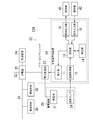
- FIG. 1 is a block diagram illustrating an embodiment of the present invention. It is operation
- 4A and 4B are explanatory diagrams showing an operation example of the embodiment. It is a figure which shows the example of data for evaluating the grade of degradation in the embodiment. It is a block diagram which shows the other structural example of the embodiment. It is a block diagram which shows another structural example of the embodiment.
- the charge and discharge management device 10 is housed in a housing 22A of a power conditioner 22 including the power conversion unit 23 as an example.
- the charge and discharge management device 10 may be separated from the power conditioner 22.
- the power conditioner 22 may be configured by the charge and discharge management device 10 and the power conversion unit 23, and the power conditioner 22 may configure the power storage device 20 housed in the storage battery 21 and one case. .
- the power conditioner 22 is configured to be connected to a distribution network 31 that supplies power to at least one (a plurality of electrical loads in the example of FIG. 1) electrical loads 30. Further, the power conditioner 22 is configured to bidirectionally exchange power between the power distribution network 31 and the storage battery 21. That is, power for charging the storage battery 21 is supplied from the distribution network 31, and the storage battery 21 has a function for supplying power to the distribution network 31.
- the range of the distribution network 31 through which the storage battery 21 delivers and receives power is set within a range separated by a division of responsibility set for a residential or business building, or in various facilities such as parks, sports fields, and streets. It is within the range divided by the responsibility demarcation point.
- the power conditioner 22 is configured to convert power in two directions between the storage battery 21 and the distribution network 31, manages charging and discharging of the storage battery 21, and operates the power conversion unit 23. And a charge / discharge management device 10 configured to instruct.
- the power conversion unit 23 bi-directionally performs power conversion between alternating current and direct current when the distribution network 31 is connected to a commercial power supply, and when the distribution network 31 supplies direct current power, power conversion between direct currents is performed. In both directions.
- the configuration of the power conversion unit 23 can be variously selected. That is, the technology of the charge and discharge management device 10 described in the present embodiment can be used in combination with the power conversion unit 23 of various configurations.
- the distribution network 31 is generally connected to a power system of a commercial power supply, but may be connected to a distributed power supply such as a solar power generation device or a fuel cell. Also, it may be connected to both the power system and the distributed power supply.
- FIG. 1 illustrates the case where the distribution network 31 is connected only to the power grid 32.
- a distribution board 33 is provided between the distribution network 31 and the power system 32.
- a measuring device 34 is provided adjacent to the distribution board 33.
- the measuring device 34 has a function for measuring the power consumed by the electric load 30 for each branch circuit branched by the distribution board 33, a function for measuring the power consumption in the main circuit before the branch, and the like. . Note that the total power consumption measured for each branch circuit may be replaced with the power consumption in the main circuit.
- the life of the storage battery 21 includes the type of the storage battery 21, the depth of discharge to the storage battery 21, the temperature of the storage battery 21, the number of times of charging and discharging of the storage battery 21, the size of the charging current of the storage battery 21, the size of the discharging current of the storage battery 21, etc. It is known to depend on various conditions.
- the temperature of the storage battery 21 is simply referred to as the battery temperature.
- lithium ion storage batteries are mainly used as the large-capacity storage batteries 21 that exchange electric power with the distribution network 31, but lead storage batteries may also be used.
- the storage battery 21 uses a chemical reaction, it is not preferable to perform charge and discharge in an environment where the battery temperature is high or low, and charge or discharge in a state where the battery temperature is high or low. Will shorten the life.
- the life of the storage battery 21 is often represented by the number of repetitions of charge and discharge (cycle life) in which the discharge capacity is reduced to 50 to 60% of the nominal capacity. Further, in applications where it is not possible to clearly measure the number of repetitions of charge and discharge, such as an uninterruptible power supply, the life of the storage battery 21 is often represented by a use time (calendar life).
- the purpose of this embodiment is to prevent the life of the storage battery 21 from being shortened by suppressing the magnitude of the charging current and the magnitude of the discharging current in an environment where the battery temperature is high or low. Therefore, the charge and discharge management device 10 manages the charge and discharge of the storage battery 21 focusing on the battery temperature.
- the charge and discharge management device 10 includes an instruction unit 11 having a function configured to instruct the power conversion unit 23 to indicate the magnitude of the charging current to the storage battery 21 and the magnitude of the discharging current from the storage battery 21. Furthermore, the charge / discharge management device 10 is configured to obtain the battery temperature of the storage battery 21, and the magnitude of the charge current and the upper limit value of the discharge current according to the temperature acquired by the temperature acquisition unit 12. And a setting unit 13 configured to determine
- the charge / discharge management device 10 includes a device including a processor (computer) configured to execute a program as a main hardware element.
- This type of device is selected from a central processing unit (CPU) that is independently provided with a processor and used with a memory, a microcomputer provided with a processor and a memory, and a field-programmable gate array (FPGA).
- the program is recorded on a computer readable medium.
- the medium is not limited to the non-volatile semiconductor memory, and may be a recording medium such as a magneto-optical disk.
- the charge / discharge management device 10 implements the function described below by combining this type of device with the device that constitutes the interface unit and executing the program.
- the power converter 23 is selected from various known configurations. If power conversion unit 23 has a configuration for converting power in two directions, power conversion unit 23 includes, for example, a configuration including one set of bridge circuits composed of four switching elements, and an isolation transformer is interposed between two sets of bridge circuits. It is possible to adopt a configuration that has been Since the present embodiment assumes that the distribution network 31 is an alternating current path, the power conversion unit 23 is configured to perform power conversion between alternating current and direct current.
- Power conversion unit 23 includes a control unit (not shown) that controls the on / off of the switching element, and discharges from storage battery 21 in a state (charging state) to charge storage battery 21 according to an instruction from charge / discharge management device 10
- the state (discharge state) is selected (switched).
- the control unit switches the operation of the switching element to switch between charging the storage battery 21 and discharging the storage battery 21, whereby the power conversion unit 23 switches between the charged state and the discharged state.
- the control unit is also configured to adjust the magnitude of the charging current and the magnitude of the discharging current by adjusting at least one of the on period and the off period of the switching element. That is, the control unit performs on / off control of the switching element according to at least one of the PWM control and the PFM control according to the content of the instruction from the instruction unit 11.
- the instruction unit 11 not only gives the power conversion unit 23 an instruction to charge the storage battery 21 or discharge the storage battery 21, but it also sets the size of the charging current and the upper limit value of the discharging current determined by the setting unit 13
- the control unit of the conversion unit 23 is configured to be instructed.
- the control unit of power conversion unit 23 adjusts the charging current to have the instructed magnitude of the charging current, and the discharge current is kept below the upper limit value. Limit the charging current.
- the temperature acquisition unit 12 is configured to intermittently acquire the temperature measured by the temperature sensor 24 configured to detect the battery temperature.
- the temperature acquisition unit 12 is configured to acquire the battery temperature in a constant cycle.
- the temperature sensor 24 adopts a configuration for notifying the temperature acquiring unit 12 of the temperature when the change in battery temperature exceeds the predetermined temperature, the temperature acquiring unit 12 acquires the battery temperature at a constant cycle. It does not have to be.
- the temperature sensor 24 includes the temperature of the outer surface of the storage battery 21, the internal temperature of the housing for storing the storage battery 21 (example shown in the figure), the internal temperature of the storage battery 21, the temperature of the environment using the storage battery 21 (outside temperature, etc. Are arranged to measure the temperature selected from Since these temperatures reflect the internal temperature of the storage battery 21 which is the temperature environment at the time of charge and discharge of the storage battery 21, they can be handled equivalently to the battery temperature.
- a difference occurs between the temperature measured by the temperature sensor 24 and the actual battery temperature depending on where the temperature sensor 24 is disposed, and the battery temperature follows the change in the temperature measured by the temperature sensor 24. Sex is also different. Therefore, it is preferable that the charge / discharge management device 10 correct the temperature measured by the temperature sensor 24 according to the place where the temperature sensor 24 is disposed before performing the following operation.
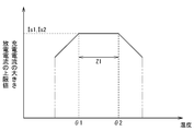
- the setting unit 13 has a function of determining the size of the charging current and a function of determining the upper limit value of the discharging current according to the battery temperature acquired by the temperature acquiring unit 12 from the temperature sensor 24. As shown in FIG. 2, setting unit 13 defines a normal range Z1 for the battery temperature, and depending on whether the battery temperature is in the normal range Z1 or deviates from the normal range Z1, the magnitude of the charging current and Change the upper limit of the discharge current.
- FIG. 2 conceptually shows the relationship between the magnitude of the charge current or the upper limit value of the discharge current and the battery temperature, and the magnitude of the charge current and the upper limit value of the discharge current are actually different values. become.
- the setting unit 13 determines the magnitude of the charging current to the prescribed first standard value Is1, and sets the upper limit value of the discharge current to the prescribed second standard value Is2. Determined.
- the setting unit 13 makes the magnitude of the charging current smaller than the first standard value Is1, and the upper limit value of the discharge current is larger than the second standard value Is2. Make it smaller.
- the magnitude of the charging current becomes larger in difference with the first standard value Is1 as the degree that the battery temperature deviates from the normal range Z1 increases. It is determined as follows. Further, the upper limit value of the discharge current is determined such that the difference with the second standard value Is2 increases as the degree of the battery temperature deviating from the normal range Z1 increases.
- the magnitude of the charging current and the upper limit value of the discharging current become constant values when the battery temperature is in the normal range Z1. That is, the magnitude of the charge current is the first standard value Is1, and the upper limit of the discharge current is the second standard value Is2.
- the battery temperature deviates from the normal range Z1
- the difference between the lower limit value or the upper limit value of the normal range Z1 and the smaller difference from the battery temperature is obtained. Furthermore, the magnitude of the charge current is reduced from the first standard value Is1 according to the difference, and the upper limit of the discharge current is reduced from the second standard value Is2 according to the difference.
- the magnitude of the charge current is Is 1 ⁇ ⁇ ⁇
- the upper limit value of the discharge current is Is 2 ⁇ ⁇ ⁇ become. Therefore, the magnitude of the charge current and the upper limit value of the discharge current become smaller as the degree of deviation of the battery temperature ⁇ x from the normal range Z1 increases.
- the setting unit 13 does not need to set the magnitude of the charging current and the upper limit value of the discharging current as continuous values (analog values), and may set them as discrete values (digital values) at appropriate intervals.
- the magnitude of the charge current and the upper limit value of the discharge current are discrete values and the interval of one step is ⁇ I
- the magnitude of the charge current is It is expressed by Is1-n ⁇ ⁇ I
- the upper limit value of the discharge current is expressed by Is2-m ⁇ ⁇ I.
- n and m are natural numbers.
- the operations of the temperature acquisition unit 12 and the setting unit 13 described above are summarized as shown in FIG.
- the temperature acquisition unit 12 acquires the battery temperature from the temperature sensor 24 at a constant sampling cycle.
- the temperature acquisition unit 12 acquires the battery temperature ⁇ x for each sampling cycle (S11).
- the setting unit 13 compares the battery temperature ⁇ x with the lower limit value ⁇ 1 and the upper limit value ⁇ 2 of the normal range Z1 (S12).
- setting unit 13 sets the magnitude of the charging current to first standard value Is1 and sets the upper limit value of discharge current.
- the second standard value Is2 is set (S13).
- the magnitude of the charging current is determined as Is1 ⁇ ⁇ ⁇ using the combination of the first standard value Is1 and the coefficient ⁇ , and the combination of the second standard value Is2 and the coefficient ⁇
- the upper limit value of the discharge current is determined as Is2- ⁇ ⁇ ⁇ using (S16).
- the determined magnitude of the charging current and the upper limit value of the discharge current are given to the instructing unit 11, and the instructing unit 11 instructs the operation of the power conversion unit 23 using the value given from the setting unit 13 (S17). The above-described process is repeated for each sampling cycle (S18).
- the magnitude of the charge current or the upper limit value of the discharge current is as shown in FIG. 4B.
- the magnitude of the charging current and the upper limit value of the discharge current are determined as a linear function of the difference ⁇ . It is also possible to express it by a quadratic function or another relation.
- the coefficient ⁇ used during charging may be set equal to the coefficient ⁇ used during discharging, and the coefficients ⁇ and ⁇ may be different between when the battery temperature exceeds the normal range Z1 and when the battery temperature does not reach the normal range Z1. May be
- setting unit 13 determines the magnitude of the charging current of storage battery 21 and the upper limit value of the discharging current when the battery temperature deviates from normal range Z1. It can be changed relatively slowly without changing rapidly.
- the magnitude of the charging current changes in accordance with the degree to which the battery temperature deviates from the normal range Z1, the magnitude of the charging current does not change rapidly, and the stress on the storage battery 21 or the vibration of the charging current Will be suppressed.
- the setting unit 13 changes the upper limit value of the discharge current according to the extent to which the battery temperature deviates from the normal range Z1, the discharge current is prevented from being greatly reduced suddenly.
- the upper limit value for limiting the discharge current is changed according to the battery temperature ⁇ x, and the discharge current is suppressed in an environment where the battery temperature ⁇ x is high or low temperature deviated from the normal range Z1. Stress is suppressed.
- setting unit 13 may have a function of stopping charging of storage battery 21 or discharging from storage battery 21 when difference ⁇ reaches a predetermined limit value. That is, the setting unit 13 reduces the magnitude of the charging current or the upper limit of the discharging current as the difference ⁇ increases, but it is desirable to stop charging or discharging when the difference ⁇ reaches the limit value. Thus, the function of the storage battery 21 can be protected by preventing the state in which the difference ⁇ is large from continuing.
- the life of the storage battery 21 is often expressed by a cycle life or a calendar life as described above.
- deterioration progresses.
- the storage capacity at the time of full charge decreases and the battery voltage decreases as the deterioration of the storage battery 21 progresses. Therefore, in the storage battery 21 in which the deterioration has progressed, the magnitude of the charging current and the allowable range for the discharge current are narrower than in the storage battery 21 in which the deterioration has not progressed.
- the charge / discharge management device 10 of the present embodiment evaluates the degree of deterioration of the storage battery 21, and the magnitude of the charge current and the upper limit value of the discharge current increase as the degree of deterioration of the storage battery 21 advances.
- a correction unit 14 configured to pull down is provided. Although the correction unit 14 is not essential, it is desirable to provide it.
- the correction unit 14 obtains an index value for expressing the degree of deterioration of the storage battery 21, and uses the index value to correct the magnitude of the charging current and the upper limit value of the discharging current.
- the index value the number of repetitions of charge and discharge or the use time is used based on the cycle life or calendar life.
- the correction unit 14 also uses the change in the storage capacity and the battery voltage with the deterioration of the storage battery 21, measures the discharged charge amount and the change width of the battery voltage before and after the discharge, and combines the two It may be converted into an index value of the degree of deterioration.
- the combination of the discharged charge amount and the change width of the battery voltage before and after the discharge is converted into the index value using a data table.
- This data table can be set based on the relationship as shown in FIG.
- the plurality of curves in FIG. 5 each represent the degree of deterioration, and the index value of the degree of deterioration corresponds to which curve the relationship between the discharged charge amount and the change width of the battery voltage before and after the discharge matches. can get.
- the correction unit 14 reduces the magnitude of the charge current as the degree of deterioration represented by the index value progresses, and the upper limit of the discharge current Make corrections to lower the value.
- the first standard value Is1 is lowered to lower the magnitude of the charging current
- the second standard value Is2 is lowered to lower the upper limit of the discharge current.
- the relationship between the index value of the degree of deterioration and the first standard value Is1 and the second standard value Is2 is determined based on the specifications, capacity, and the like of the storage battery 21.
- the correction unit 14 performs the correction to lower the first standard value Is1 and the second standard value Is2 as the deterioration of the storage battery 21 progresses, but as the deterioration progresses, the coefficient ⁇ A configuration may be adopted in which correction is performed so as to increase .beta.
- the setting unit 13 provided in the charge / discharge management device 10 lowers the magnitude of the charge current and the upper limit value of the discharge current. .
- the power supplied to the electrical load 30 may be reduced, resulting in the loss of comfort obtained by using the electrical load 30. Therefore, it is desirable for the user to select whether to perform the operation with priority given to the life of the storage battery 21 or the operation with priority given to the use of the electric load 30.
- the charge / discharge management device 10 includes a notification output unit 15 and an instruction input unit 16, which respectively It enables the use of the alarm 41 and the controller 42 as an interface with the user.
- the notification output unit 15 is configured to output a notification signal when the battery temperature acquired from the temperature acquisition unit 12 deviates from the normal range Z1 in a period in which the storage battery 21 is being charged or discharged. In the example of FIG. 1, the notification signal is supplied to the annunciator 41. Further, the instruction input unit 16 is configured to wait for an instruction to continue or stop charging or discharging of the storage battery 21 when the notification output unit 15 outputs a notification signal.
- the instruction unit 11 has a function configured to stop charging or discharging the storage battery 21 when the instruction input unit 16 receives an instruction to stop charging or discharging the storage battery 21.
- the annunciator 41 is configured to perform both auditory notification such as a notification sound and visual notification such as a notification lamp or a notification display.
- auditory notification such as a notification sound
- visual notification such as a notification lamp or a notification display.
- the aural notification or the visual notification can be used. It may be configured to perform one side.
- An operation display may be used in which the alarm 41 includes a flat panel display, and the operation unit 42 includes a touch panel superimposed on the screen of the flat panel display.
- the annunciator 41 and the controller 42 may either have a configuration sharing the case with the charge / discharge management device 10 or may have a configuration provided with a different case from the charge / discharge management device 10 and communicate with the charge / discharge management device 10.
- the notification output unit 15 and the instruction input unit 16 use these general-purpose devices as the alarm 41 and the operation device 42. It is also good.
- the notification output unit 15 when the battery temperature deviates from the normal range Z1 during the period in which the storage battery 21 is being charged or the storage battery 21 is being discharged, the notification output unit 15 outputs an alarm The notification signal is output to 41. That is, the user is notified that the battery temperature has deviated from the normal range Z1 through the alarm 41, and the instruction input unit 16 is in a state of waiting for an input from the controller 42.
- the instruction unit 11 instructs the power conversion unit 23 to continue charging or discharging. To direct.
- instructing unit 11 instructs power conversion unit 23 to stop charging or discharging.
- the instruction input unit 16 continue charging or discharging when a state in which no input can be obtained from the operating device 42 continues for a predetermined time while waiting for an input from the operating device 42. That is, the stop of the charge or discharge of the storage battery 21 is performed only when the user operates intentionally.
- the instruction input unit 16 waits for an input from the operating device 42 in a state in which charging of the storage battery 21 or discharging from the storage battery 21 is continued, charging or discharging is performed unless a stop instruction is input. It will be continued. That is, the storage battery 21 is not given stress due to rapid change of the charging current or the discharging current.
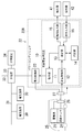
- the storage battery 21 of the configuration example described above assumes that the storage battery 21 is housed in a dedicated housing, the storage battery 21 may be mounted on the electric vehicle 25 as shown in FIG. 6.
- the electric vehicle 25 means a vehicle that can use electric power as an energy source for traveling, such as an electric car, a hybrid car, and an electric two-wheeled vehicle. Since the electric vehicle 25 of this type uses electric power as an energy source for traveling, the storage battery 21 having a relatively large capacity is mounted. Therefore, the power of the storage battery 21 can be used for the operation of the electric load 30.
- power coupling unit 26 provided on electrically powered vehicle 25 and power coupling unit 27 provided on the side of power distribution network 31 Put into a combined state.
- the power coupling unit 27 is provided on the side of the power conditioner so that it can be coupled to the power coupling unit 26.
- Power coupling unit 26 and power coupling unit 27 can select a coupled state that enables transfer of power between storage battery 21 and distribution network 31 and a separated state in which electric vehicle 25 can run. It may have any configuration.
- the power coupling unit 26 and the power coupling unit 27 can adopt a configuration that enables coupling and separation of electrical paths, as in the relation between the outlet and the plug.
- the power coupling unit 26 and the power coupling unit 27 may be configured to enable transmission of power by non-contact power feeding technology. In this case, the loss caused when transmitting the power between the storage battery 21 and the distribution network 31 is reduced by using a non-contact power feeding technology with high power transmission efficiency such as a resonance magnetic field type or a resonance electric field type. Ru.
- charge / discharge management device 10 When storage battery 21 is mounted on electrically powered vehicle 25, charge / discharge management device 10 operates in a period in which storage battery 21 is in a coupled state with distribution network 31. That is, the instruction unit 11 operates in a state in which it is detected that the power coupling unit 26 of the electric vehicle 25 is coupled to the power coupling unit 27 on the distribution network 31 side.
- the charge / discharge management device 10 may have a function configured to cooperate with the controller 40 for managing the operation of the electrical load 30.
- the charge and discharge management device 10 illustrated in FIG. 7 includes a communication interface unit 17 configured to communicate with the controller 40.
- the controller 40 is a so-called HEMS (Home Energy Management System) controller, and makes it possible to control the operation of the electrical load 30 by communicating with the electrical load 30 having a communication function.
- the controller 40 of this type contributes to control of the electricity bill paid by the consumer, reduction of the amount of power consumed by the consumer, and the like by managing the amount of power used by the consumer.
- the setting unit 13 communicates with the controller 40 through the communication interface unit 17.
- the setting unit 13 has a function configured to determine the magnitude of the charging current using the information acquired from the controller 40, and a function configured to notify the controller 40 of the set upper limit value of the discharge current. Have.
- setting unit 13 receives available power, which is the difference between the supplied power from the power supply source and the power used by electric load 30, from controller 40 during the period in which storage battery 21 is charged, and uses it.
- the available power is used to determine the magnitude of the charging current.
- the power supply source is a power supply that supplies power to the storage battery 21 and the electrical load 30, and in the illustrated example, the commercial power supply AC, but the system of FIG. 7 may include distributed power supplies.
- the setting unit 13 notifies the controller 40 of the upper limit value of the discharge current, which is an indicator of the power that can be supplied from the storage battery 21 to the electric load 30 during the period when the storage battery 21 is discharged.
- the charge / discharge management device 10 communicates with the controller 40 in this manner, it becomes possible to determine the charge current based on the available power that can be used to charge the storage battery 21. Further, by notifying the controller 40 of the upper limit value of the discharge current from the storage battery 21, it becomes possible to properly distribute the electric power stored in the storage battery 21 to the electric load 30.
- the configuration example described above adjusts both the magnitude of the charging current at the time of charging the storage battery 21 and the upper limit value of the discharging current at the time of discharging from the storage battery 21 according to the battery temperature. Only the magnitude of the charging current may be adjusted according to the battery temperature. That is, in an environment where the battery temperature is high or low with respect to the normal range, the effect of extending the life of the storage battery 21 can be expected simply by limiting the magnitude of the charging current.
Landscapes
- Engineering & Computer Science (AREA)
- Power Engineering (AREA)
- Transportation (AREA)
- Mechanical Engineering (AREA)
- Chemical Kinetics & Catalysis (AREA)
- Chemical & Material Sciences (AREA)
- Electrochemistry (AREA)
- General Chemical & Material Sciences (AREA)
- Sustainable Development (AREA)
- Sustainable Energy (AREA)
- Life Sciences & Earth Sciences (AREA)
- Manufacturing & Machinery (AREA)
- Charge And Discharge Circuits For Batteries Or The Like (AREA)
- Secondary Cells (AREA)
Abstract
La présente invention se rapporte à un dispositif de gestion de charge/décharge qui comprend une unité d'indication, une unité d'acquisition de température et une unité de réglage afin de gérer les états de charge et de décharge d'une pile rechargeable utilisée pour transmettre de l'énergie à un réseau de distribution, et recevoir de l'énergie de ce réseau de distribution qui fournit l'énergie à des charges électriques. L'unité d'indication indique l'amplitude d'un courant avec lequel la pile rechargeable est chargée. L'unité d'acquisition de température acquiert la température de la pile rechargeable. L'unité de réglage établit l'amplitude du courant de charge à une première valeur standard lorsque la température de la pile se situe dans une plage normale. Lorsque la température de la pile s'écarte de la plage normale, l'unité de réglage règle le courant de charge de telle sorte que le courant de charge soit inférieur à la première valeur standard et de telle sorte qu'un degré d'écart plus important par rapport à la plage normale corresponde à une différence plus importante entre le courant de charge et la première valeur standard.
Priority Applications (2)
| Application Number | Priority Date | Filing Date | Title |
|---|---|---|---|
| EP13860892.2A EP2930820A4 (fr) | 2012-12-05 | 2013-11-13 | Dispositif de gestion de charge/décharge, système de conditionnement d'énergie, dispositif de stockage d'énergie, et programme |
| US14/441,624 US20150291044A1 (en) | 2012-12-05 | 2013-11-13 | Charge-discharge management device, power conditioner, power storage device, and program |
Applications Claiming Priority (2)
| Application Number | Priority Date | Filing Date | Title |
|---|---|---|---|
| JP2012266509A JP2014113006A (ja) | 2012-12-05 | 2012-12-05 | 充放電管理装置、パワーコンディショナ、蓄電装置、プログラム |
| JP2012-266509 | 2012-12-05 |
Publications (1)
| Publication Number | Publication Date |
|---|---|
| WO2014087580A1 true WO2014087580A1 (fr) | 2014-06-12 |
Family
ID=50883022
Family Applications (1)
| Application Number | Title | Priority Date | Filing Date |
|---|---|---|---|
| PCT/JP2013/006665 Ceased WO2014087580A1 (fr) | 2012-12-05 | 2013-11-13 | Dispositif de gestion de charge/décharge, système de conditionnement d'énergie, dispositif de stockage d'énergie, et programme |
Country Status (4)
| Country | Link |
|---|---|
| US (1) | US20150291044A1 (fr) |
| EP (1) | EP2930820A4 (fr) |
| JP (1) | JP2014113006A (fr) |
| WO (1) | WO2014087580A1 (fr) |
Cited By (5)
| Publication number | Priority date | Publication date | Assignee | Title |
|---|---|---|---|---|
| CN104716717A (zh) * | 2015-04-08 | 2015-06-17 | 南车株洲电力机车有限公司 | 一种悬浮蓄电池管理系统和方法 |
| DE102015213029A1 (de) * | 2015-07-13 | 2017-01-19 | Bayerische Motoren Werke Aktiengesellschaft | Versorgungssystem, Kraftfahrzeug und Verfahren zur Bereitstellung von elektrischer Energie |
| WO2017130614A1 (fr) * | 2016-01-27 | 2017-08-03 | 日立オートモティブシステムズ株式会社 | Dispositif de commande de batterie |
| WO2019073508A1 (fr) * | 2017-10-10 | 2019-04-18 | Tdk株式会社 | Système d'alimentation électrique cc |
| CN112582708A (zh) * | 2020-12-14 | 2021-03-30 | 无锡市神韵科技发展有限公司 | 一种基于电动车的人机交互网络控制系统 |
Families Citing this family (31)
| Publication number | Priority date | Publication date | Assignee | Title |
|---|---|---|---|---|
| JP6179054B2 (ja) * | 2013-07-02 | 2017-08-16 | パナソニックIpマネジメント株式会社 | 双方向dc/dcコンバータ、双方向電力変換器 |
| JP6420107B2 (ja) * | 2014-09-30 | 2018-11-07 | 近畿車輌株式会社 | ハイブリッド車両の蓄電池加熱システム |
| US10031567B2 (en) * | 2015-06-09 | 2018-07-24 | Microsoft Technology Licensing, Llc | Offline battery management in a device |
| WO2017147612A1 (fr) | 2016-02-25 | 2017-08-31 | California Institute Of Technology | Réseau de charge adaptative utilisant des stations de charge adaptative pour véhicules électriques |
| US20170271984A1 (en) | 2016-03-04 | 2017-09-21 | Atigeo Corp. | Using battery dc characteristics to control power output |
| JP6562856B2 (ja) * | 2016-03-17 | 2019-08-21 | 株式会社クボタ | 多目的車両 |
| CN105904985B (zh) * | 2016-04-25 | 2018-09-04 | 李东航 | 一种电动汽车充电控制装置 |
| JP6705706B2 (ja) * | 2016-06-22 | 2020-06-03 | 株式会社マキタ | バッテリ装置 |
| FR3058844B1 (fr) * | 2016-11-17 | 2020-01-03 | Seb S.A. | Circuit electrique pour un appareil electroportatif |
| KR102225431B1 (ko) * | 2016-12-21 | 2021-03-08 | 가부시키가이샤 지에스 유아사 | 축전 소자의 관리 장치, 축전 장치, 태양광 발전 시스템, 열화량의 추정 방법 및 컴퓨터 프로그램 |
| CN107499163B (zh) * | 2017-08-21 | 2019-12-06 | 中国能源建设集团江苏省电力设计院有限公司 | 一种适用于电动汽车充电站的充电控制方法 |
| US10418836B2 (en) * | 2017-08-24 | 2019-09-17 | Microsoft Technology Licensing, Llc | Devices, systems, and methods for temperature based limiting of battery pack discharge |
| US10948546B2 (en) * | 2017-10-02 | 2021-03-16 | Semiconductor Components Industries, Llc | Methods and apparatus for battery management |
| EP3718073A4 (fr) * | 2017-12-01 | 2021-08-25 | California Institute of Technology | Cadriciel et procédés d'optimisation de charge adaptative d'ev |
| US10639998B2 (en) * | 2018-04-20 | 2020-05-05 | Ford Global Technologies, Llc | Service disconnect notification strategy |
| CN111497672B (zh) * | 2019-01-30 | 2021-11-19 | 北京新能源汽车股份有限公司 | 一种车辆充电热管理的控制方法及装置 |
| US11376981B2 (en) | 2019-02-08 | 2022-07-05 | California Institute Of Technology | Systems and methods for adaptive EV charging |
| FR3106535B1 (fr) * | 2020-01-24 | 2024-02-16 | Psa Automobiles Sa | Procédé et dispositif de contrôle d’un système de stockage d’énergie, par exemple une batterie de véhicule |
| JP7550536B2 (ja) * | 2020-05-28 | 2024-09-13 | キヤノン株式会社 | 電子機器、制御方法およびプログラム |
| CN112003273A (zh) * | 2020-08-12 | 2020-11-27 | 杭州海兴泽科信息技术有限公司 | 一种光伏并网系统功率的控制方法 |
| WO2022118681A1 (fr) * | 2020-12-04 | 2022-06-09 | 株式会社椿本チエイン | Dispositif de charge et de décharge, procédé de commande de charge/décharge et programme informatique |
| CN112793468A (zh) * | 2020-12-31 | 2021-05-14 | 江铃汽车股份有限公司 | 一种电池充放电保护方法、系统、存储介质及设备 |
| JP7771516B2 (ja) * | 2021-02-22 | 2025-11-18 | カシオ計算機株式会社 | 電子機器、情報出力方法及びプログラム |
| CN113553534B (zh) * | 2021-07-05 | 2024-09-03 | 广州小鹏汽车科技有限公司 | 快充充电剩余时间的计算方法及装置、车辆、存储介质 |
| CN113479099A (zh) * | 2021-07-07 | 2021-10-08 | 华人运通(江苏)技术有限公司 | 一种取电补电的控制方法及系统 |
| CN113968160B (zh) * | 2021-09-29 | 2023-10-20 | 华人运通(江苏)技术有限公司 | 车辆充电时间预估方法、装置、设备及存储介质 |
| JP7718756B2 (ja) * | 2023-04-27 | 2025-08-05 | Necプラットフォームズ株式会社 | 充電装置、充電方法、及びプログラム |
| KR20260003797A (ko) * | 2023-05-04 | 2026-01-07 | 사파이어 테크놀로지 그룹, 인크. | 이중 셀 뱅크 배터리를 제어하기 위한 시스템 및 방법 |
| CN116885826B (zh) * | 2023-09-06 | 2024-07-26 | 荣耀终端有限公司 | 充电方法、电子设备及计算机可读存储介质 |
| CN118508573B (zh) * | 2024-07-16 | 2024-09-27 | 深圳市美富达电子有限公司 | 智能设备充电方法、装置、电子设备及介质 |
| CN119348501B (zh) * | 2024-12-09 | 2025-09-16 | 岚图汽车科技有限公司 | 一种电池管理系统的控制方法、装置及控制器 |
Citations (9)
| Publication number | Priority date | Publication date | Assignee | Title |
|---|---|---|---|---|
| JPH10174297A (ja) * | 1996-12-17 | 1998-06-26 | Yamaha Motor Co Ltd | 蓄電池の放電制御方法及びその装置 |
| JPH11178234A (ja) * | 1997-12-10 | 1999-07-02 | Nissan Motor Co Ltd | 電気自動車を用いた家庭用電力供給システム |
| JPH11187577A (ja) * | 1997-10-13 | 1999-07-09 | Toyota Motor Corp | 二次電池の充放電制御装置 |
| JP2000295784A (ja) * | 1999-04-08 | 2000-10-20 | Sekisui Chem Co Ltd | 電力貯蔵システム |
| JP2006203978A (ja) | 2005-01-18 | 2006-08-03 | Nec Tokin Corp | 無停電電源装置 |
| JP2007259509A (ja) | 2006-03-20 | 2007-10-04 | Hitachi Maxell Ltd | 電源システムおよびそれを備えたセンサシステム |
| JP2010060408A (ja) * | 2008-09-03 | 2010-03-18 | Toyota Motor Corp | リチウムイオン電池の劣化判定方法、リチウムイオン電池の制御方法、リチウムイオン電池の劣化判定装置、リチウムイオン電池の制御装置及び車両 |
| JP2011015591A (ja) * | 2009-07-06 | 2011-01-20 | Hitachi Koki Co Ltd | 電池パック及び充電システム |
| JP2011153952A (ja) * | 2010-01-28 | 2011-08-11 | Mitsumi Electric Co Ltd | 監視機能付き保護モジュール |
Family Cites Families (11)
| Publication number | Priority date | Publication date | Assignee | Title |
|---|---|---|---|---|
| JP4134877B2 (ja) * | 2003-10-20 | 2008-08-20 | トヨタ自動車株式会社 | 蓄電機構の制御装置 |
| JP4494453B2 (ja) * | 2007-11-13 | 2010-06-30 | トヨタ自動車株式会社 | 二次電池の制御装置および制御方法 |
| JP5219485B2 (ja) * | 2007-12-12 | 2013-06-26 | 三洋電機株式会社 | 充電方法 |
| US8344700B2 (en) * | 2008-03-03 | 2013-01-01 | Panasonic Corporation | Charging method and charger |
| JP5309641B2 (ja) * | 2008-03-24 | 2013-10-09 | ミツミ電機株式会社 | 充電制御用半導体集積回路 |
| JP5430994B2 (ja) * | 2009-03-27 | 2014-03-05 | 株式会社日本総合研究所 | 充放電制御装置、及び充放電制御方法 |
| CN102474124B (zh) * | 2009-11-20 | 2013-08-14 | 松下电器产业株式会社 | 充电控制电路、电池组件以及充电系统 |
| US8710802B2 (en) * | 2010-05-14 | 2014-04-29 | Blackberry Limited | Method and apparatus for charging a power pack of a portable electronic device |
| US20130181683A1 (en) * | 2012-01-17 | 2013-07-18 | Richtek Technology Corporation, R.O.C. | Battery Charging Circuit and Reference Signal Generator |
| WO2013165371A1 (fr) * | 2012-04-30 | 2013-11-07 | Hewlett-Packard Development Company, L.P. | Charge d'accumulation d'énergie provenant d'une source de courant réglable |
| TWI464997B (zh) * | 2012-05-02 | 2014-12-11 | 緯創資通股份有限公司 | 電池充電電路 |
-
2012
- 2012-12-05 JP JP2012266509A patent/JP2014113006A/ja active Pending
-
2013
- 2013-11-13 US US14/441,624 patent/US20150291044A1/en not_active Abandoned
- 2013-11-13 WO PCT/JP2013/006665 patent/WO2014087580A1/fr not_active Ceased
- 2013-11-13 EP EP13860892.2A patent/EP2930820A4/fr not_active Withdrawn
Patent Citations (9)
| Publication number | Priority date | Publication date | Assignee | Title |
|---|---|---|---|---|
| JPH10174297A (ja) * | 1996-12-17 | 1998-06-26 | Yamaha Motor Co Ltd | 蓄電池の放電制御方法及びその装置 |
| JPH11187577A (ja) * | 1997-10-13 | 1999-07-09 | Toyota Motor Corp | 二次電池の充放電制御装置 |
| JPH11178234A (ja) * | 1997-12-10 | 1999-07-02 | Nissan Motor Co Ltd | 電気自動車を用いた家庭用電力供給システム |
| JP2000295784A (ja) * | 1999-04-08 | 2000-10-20 | Sekisui Chem Co Ltd | 電力貯蔵システム |
| JP2006203978A (ja) | 2005-01-18 | 2006-08-03 | Nec Tokin Corp | 無停電電源装置 |
| JP2007259509A (ja) | 2006-03-20 | 2007-10-04 | Hitachi Maxell Ltd | 電源システムおよびそれを備えたセンサシステム |
| JP2010060408A (ja) * | 2008-09-03 | 2010-03-18 | Toyota Motor Corp | リチウムイオン電池の劣化判定方法、リチウムイオン電池の制御方法、リチウムイオン電池の劣化判定装置、リチウムイオン電池の制御装置及び車両 |
| JP2011015591A (ja) * | 2009-07-06 | 2011-01-20 | Hitachi Koki Co Ltd | 電池パック及び充電システム |
| JP2011153952A (ja) * | 2010-01-28 | 2011-08-11 | Mitsumi Electric Co Ltd | 監視機能付き保護モジュール |
Non-Patent Citations (1)
| Title |
|---|
| See also references of EP2930820A4 |
Cited By (6)
| Publication number | Priority date | Publication date | Assignee | Title |
|---|---|---|---|---|
| CN104716717A (zh) * | 2015-04-08 | 2015-06-17 | 南车株洲电力机车有限公司 | 一种悬浮蓄电池管理系统和方法 |
| DE102015213029A1 (de) * | 2015-07-13 | 2017-01-19 | Bayerische Motoren Werke Aktiengesellschaft | Versorgungssystem, Kraftfahrzeug und Verfahren zur Bereitstellung von elektrischer Energie |
| WO2017130614A1 (fr) * | 2016-01-27 | 2017-08-03 | 日立オートモティブシステムズ株式会社 | Dispositif de commande de batterie |
| US10840722B2 (en) | 2016-01-27 | 2020-11-17 | Vehicle Energy Japan, Inc. | Battery control device |
| WO2019073508A1 (fr) * | 2017-10-10 | 2019-04-18 | Tdk株式会社 | Système d'alimentation électrique cc |
| CN112582708A (zh) * | 2020-12-14 | 2021-03-30 | 无锡市神韵科技发展有限公司 | 一种基于电动车的人机交互网络控制系统 |
Also Published As
| Publication number | Publication date |
|---|---|
| JP2014113006A (ja) | 2014-06-19 |
| US20150291044A1 (en) | 2015-10-15 |
| EP2930820A1 (fr) | 2015-10-14 |
| EP2930820A4 (fr) | 2015-11-25 |
Similar Documents
| Publication | Publication Date | Title |
|---|---|---|
| WO2014087580A1 (fr) | Dispositif de gestion de charge/décharge, système de conditionnement d'énergie, dispositif de stockage d'énergie, et programme | |
| CN106663944B (zh) | 电存储系统 | |
| CN105210258B (zh) | 用于产生可动态重配置的储能装置的方法和设备 | |
| JP6332924B2 (ja) | セルバランシング回路およびこれを用いたセルバランシング方法 | |
| US9653928B2 (en) | Battery pack including sensing board and power storage system employing the same | |
| JP4691140B2 (ja) | 充放電システムおよび携帯式コンピュータ | |
| US20150035359A1 (en) | Energy storage system of uninterruptible power supply equipped with battery and method of driving the same | |
| US9531212B2 (en) | Secondary battery system and charge and discharge method for the same | |
| US20130187465A1 (en) | Power management system | |
| KR20130024763A (ko) | 셀 밸런싱 방법, 셀 밸런싱 장치, 및 이를 포함하는 에너지 저장 시스템 | |
| JPWO2013042517A1 (ja) | スイッチ装置及びブレーカ制御方法 | |
| CN101872994A (zh) | 电池充电器及其充电方法 | |
| CN102593884A (zh) | 电池系统和包括其的能量存储系统 | |
| JP2012196123A (ja) | 地域内電力需要管理システム | |
| EP2757652A1 (fr) | Système de batterie secondaire, et procédé de fonctionnement de batterie secondaire | |
| WO2015118844A1 (fr) | Dispositif de gestion d'énergie et procédé de gestion d'énergie | |
| TW201505324A (zh) | 電池模組、電池模組供電管理方法及其裝置 | |
| WO2015001767A1 (fr) | Dispositif de commande et système de gestion d'énergie | |
| JP6993286B2 (ja) | 蓄電装置、蓄電装置の制御装置及び蓄電装置の制御方法 | |
| CN107078361A (zh) | 蓄电池容量测量装置 | |
| CN119696003A (zh) | 多储能单元的协同控制方法及装置 | |
| KR20140078322A (ko) | 태양광 충전이 가능한 휴대용 에너지 저장 배터리팩 전원 시스템 | |
| KR101201811B1 (ko) | 충방전 장치 | |
| WO2022046117A1 (fr) | Circuit de chargeur parallèle avec commande de rétroaction de batterie | |
| US20240291053A1 (en) | Apparatus and a method for management of sodium-based rechargeable batteries |
Legal Events
| Date | Code | Title | Description |
|---|---|---|---|
| 121 | Ep: the epo has been informed by wipo that ep was designated in this application |
Ref document number: 13860892 Country of ref document: EP Kind code of ref document: A1 |
|
| WWE | Wipo information: entry into national phase |
Ref document number: 14441624 Country of ref document: US |
|
| REEP | Request for entry into the european phase |
Ref document number: 2013860892 Country of ref document: EP |
|
| WWE | Wipo information: entry into national phase |
Ref document number: 2013860892 Country of ref document: EP |
|
| NENP | Non-entry into the national phase |
Ref country code: DE |