WO2014088027A1 - 車高調整装置 - Google Patents
車高調整装置 Download PDFInfo
- Publication number
- WO2014088027A1 WO2014088027A1 PCT/JP2013/082576 JP2013082576W WO2014088027A1 WO 2014088027 A1 WO2014088027 A1 WO 2014088027A1 JP 2013082576 W JP2013082576 W JP 2013082576W WO 2014088027 A1 WO2014088027 A1 WO 2014088027A1
- Authority
- WO
- WIPO (PCT)
- Prior art keywords
- spring
- vehicle height
- spring receiver
- movable spring
- movable
- Prior art date
- Legal status (The legal status is an assumption and is not a legal conclusion. Google has not performed a legal analysis and makes no representation as to the accuracy of the status listed.)
- Ceased
Links
Images


Classifications
-
- B—PERFORMING OPERATIONS; TRANSPORTING
- B60—VEHICLES IN GENERAL
- B60G—VEHICLE SUSPENSION ARRANGEMENTS
- B60G17/00—Resilient suspensions having means for adjusting the spring or vibration-damper characteristics, for regulating the distance between a supporting surface and a sprung part of vehicle or for locking suspension during use to meet varying vehicular or surface conditions, e.g. due to speed or load
- B60G17/02—Spring characteristics, e.g. mechanical springs and mechanical adjusting means
- B60G17/027—Mechanical springs regulated by fluid means
- B60G17/0272—Mechanical springs regulated by fluid means the mechanical spring being a coil spring
-
- F—MECHANICAL ENGINEERING; LIGHTING; HEATING; WEAPONS; BLASTING
- F16—ENGINEERING ELEMENTS AND UNITS; GENERAL MEASURES FOR PRODUCING AND MAINTAINING EFFECTIVE FUNCTIONING OF MACHINES OR INSTALLATIONS; THERMAL INSULATION IN GENERAL
- F16F—SPRINGS; SHOCK-ABSORBERS; MEANS FOR DAMPING VIBRATION
- F16F1/00—Springs
- F16F1/02—Springs made of steel or other material having low internal friction; Wound, torsion, leaf, cup, ring or the like springs, the material of the spring not being relevant
- F16F1/04—Wound springs
- F16F1/12—Attachments or mountings
- F16F1/121—Attachments or mountings adjustable, e.g. to modify spring characteristics
-
- F—MECHANICAL ENGINEERING; LIGHTING; HEATING; WEAPONS; BLASTING
- F16—ENGINEERING ELEMENTS AND UNITS; GENERAL MEASURES FOR PRODUCING AND MAINTAINING EFFECTIVE FUNCTIONING OF MACHINES OR INSTALLATIONS; THERMAL INSULATION IN GENERAL
- F16F—SPRINGS; SHOCK-ABSORBERS; MEANS FOR DAMPING VIBRATION
- F16F9/00—Springs, vibration-dampers, shock-absorbers, or similarly-constructed movement-dampers using a fluid or the equivalent as damping medium
- F16F9/32—Details
- F16F9/38—Covers for protection or appearance
-
- F—MECHANICAL ENGINEERING; LIGHTING; HEATING; WEAPONS; BLASTING
- F16—ENGINEERING ELEMENTS AND UNITS; GENERAL MEASURES FOR PRODUCING AND MAINTAINING EFFECTIVE FUNCTIONING OF MACHINES OR INSTALLATIONS; THERMAL INSULATION IN GENERAL
- F16F—SPRINGS; SHOCK-ABSORBERS; MEANS FOR DAMPING VIBRATION
- F16F9/00—Springs, vibration-dampers, shock-absorbers, or similarly-constructed movement-dampers using a fluid or the equivalent as damping medium
- F16F9/32—Details
- F16F9/56—Means for adjusting the length of, or for locking, the spring or damper, e.g. at the end of the stroke
-
- B—PERFORMING OPERATIONS; TRANSPORTING
- B60—VEHICLES IN GENERAL
- B60G—VEHICLE SUSPENSION ARRANGEMENTS
- B60G17/00—Resilient suspensions having means for adjusting the spring or vibration-damper characteristics, for regulating the distance between a supporting surface and a sprung part of vehicle or for locking suspension during use to meet varying vehicular or surface conditions, e.g. due to speed or load
- B60G17/02—Spring characteristics, e.g. mechanical springs and mechanical adjusting means
- B60G17/04—Spring characteristics, e.g. mechanical springs and mechanical adjusting means fluid spring characteristics
- B60G17/052—Pneumatic spring characteristics
- B60G17/0523—Regulating distributors or valves for pneumatic springs
- B60G17/0525—Height adjusting or levelling valves
-
- B—PERFORMING OPERATIONS; TRANSPORTING
- B60—VEHICLES IN GENERAL
- B60G—VEHICLE SUSPENSION ARRANGEMENTS
- B60G2202/00—Indexing codes relating to the type of spring, damper or actuator
- B60G2202/30—Spring/Damper and/or actuator Units
- B60G2202/31—Spring/Damper and/or actuator Units with the spring arranged around the damper, e.g. MacPherson strut
-
- B—PERFORMING OPERATIONS; TRANSPORTING
- B60—VEHICLES IN GENERAL
- B60G—VEHICLE SUSPENSION ARRANGEMENTS
- B60G2202/00—Indexing codes relating to the type of spring, damper or actuator
- B60G2202/30—Spring/Damper and/or actuator Units
- B60G2202/31—Spring/Damper and/or actuator Units with the spring arranged around the damper, e.g. MacPherson strut
- B60G2202/312—The spring being a wound spring
-
- B—PERFORMING OPERATIONS; TRANSPORTING
- B60—VEHICLES IN GENERAL
- B60G—VEHICLE SUSPENSION ARRANGEMENTS
- B60G2202/00—Indexing codes relating to the type of spring, damper or actuator
- B60G2202/30—Spring/Damper and/or actuator Units
- B60G2202/32—The spring being in series with the damper and/or actuator
-
- B—PERFORMING OPERATIONS; TRANSPORTING
- B60—VEHICLES IN GENERAL
- B60G—VEHICLE SUSPENSION ARRANGEMENTS
- B60G2202/00—Indexing codes relating to the type of spring, damper or actuator
- B60G2202/40—Type of actuator
- B60G2202/41—Fluid actuator
- B60G2202/413—Hydraulic actuator
-
- B—PERFORMING OPERATIONS; TRANSPORTING
- B60—VEHICLES IN GENERAL
- B60G—VEHICLE SUSPENSION ARRANGEMENTS
- B60G2300/00—Indexing codes relating to the type of vehicle
- B60G2300/12—Cycles; Motorcycles
-
- B—PERFORMING OPERATIONS; TRANSPORTING
- B60—VEHICLES IN GENERAL
- B60G—VEHICLE SUSPENSION ARRANGEMENTS
- B60G2500/00—Indexing codes relating to the regulated action or device
- B60G2500/30—Height or ground clearance
- B60G2500/32—Height or ground clearance of only one vehicle part or side
- B60G2500/324—Height or ground clearance of only one vehicle part or side only rear part
Definitions
- the present invention relates to a vehicle height adjusting device.
- a shock absorber that generates a damping force and a suspension spring that urges the shock absorber in the extending direction are provided in parallel between the vehicle body and the wheel in the vehicle.
- the suspension spring absorbs an impact caused by road surface unevenness, and the shock absorber suppresses the expansion and contraction motion of the suspension spring accompanying the impact absorption. Thereby, it is suppressed that the impact by the road surface unevenness is transmitted to the vehicle body.
- a vehicle height adjusting device capable of adjusting the vehicle height is mounted on the vehicle.
- JP2010-149550A discloses a vehicle height adjusting device. As shown in FIG. 4, the vehicle height adjusting device supports one end (upper end in FIG. 4) of the suspension spring S ⁇ b> 1 that is attached to the outer periphery of the outer cylinder T of the shock absorber D and biases the shock absorber D in the extending direction. And a drive mechanism M for driving the movable spring receiver 8 in the axial direction of the shock absorber D.
- the drive mechanism M is formed between the housing 90 and the outer cylinder T, and an annular housing 90 fixed to the outer suspension spring side (upper side in FIG. 4) of the movable spring receiver 8 on the outer periphery of the outer cylinder T. Is connected to the anti-suspension spring side (upper side in FIG. 4) of the movable spring receiver 8 and is movably inserted between the housing 90 and the outer cylinder T so that the suspension spring side of the jack chamber J (Lower in FIG. 4) A jack piston 91 that closes the opening and a pump P that sucks and discharges the working fluid into the jack chamber J are provided.
- the working fluid is supplied to the jack chamber J by the pump P, whereby the jack piston 91 is pushed out from the housing 90, and the shock absorber D is extended to increase the vehicle height.
- the working fluid is discharged from the jack chamber J by the pump P, so that the jack piston 91 is pushed into the housing 90 and the shock absorber D is contracted to reduce the vehicle height. .
- JP11-182609A discloses a suspension spring force adjustment device.
- the suspension spring force adjusting device includes a dust cover 2 ⁇ / b> C that suppresses dust from adhering by covering a portion where the movable spring receiver 8 and the jack piston 91 are in sliding contact.
- the movable spring receiver 8 is sandwiched between the suspension spring S1 and the auxiliary spring, and the movable spring receiver 8 is suspended by the auxiliary spring in order to facilitate driving of the movable spring receiver 8. It is conceivable that the spring is energized in the direction in which the suspension spring S1 contracts.
- An object of the present invention is to facilitate attachment of a dust cover in a vehicle height adjusting device including an auxiliary spring.
- a vehicle height adjusting device wherein one end of a suspension spring that is in sliding contact with a guide surface formed on the outer periphery of the outer cylinder of the shock absorber and biases the shock absorber in the extending direction is provided.
- An annular movable spring receiver to be supported, a drive mechanism that drives the movable spring receiver in the axial direction of the shock absorber, an auxiliary spring that biases the movable spring receiver toward the suspension spring, and a portion in which the movable spring receiver on the guide surface is in sliding contact
- the dust cover is held by the outer cylinder by the spring force of the auxiliary spring.
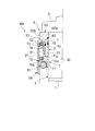
- FIG. 1 is a front view partially showing a shock absorber equipped with a vehicle height adjusting device according to a first embodiment of the present invention.
- FIG. 2 is an enlarged view showing the main part of FIG.
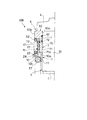
- FIG. 3 is an enlarged view showing an enlarged main part of the shock absorber equipped with the vehicle height adjusting device according to the second embodiment of the present invention.
- FIG. 4 is a front view showing a conventional shock absorber partially cut away.
- FIG. 5 is a front view showing a conventional shock absorber partially cut away.
- FIG. 1 is a front view of the shock absorber D on which the vehicle height adjusting device 100 according to this embodiment is mounted, partially cut away.
- subjected through some drawings shows the same component or a corresponding component.
- the vehicle height adjusting device 100 is in contact with a guide surface 30 formed on the outer periphery of the outer cylinder T of the shock absorber D, and on one side of the suspension spring S1 that biases the shock absorber D in the extending direction.
- An annular movable spring receiver 1 that supports the end (the upper end in FIG. 1), a drive mechanism M that drives the movable spring receiver 1 in the axial direction of the shock absorber D, and an auxiliary that biases the movable spring receiver 1 toward the suspension spring.
- a spring S2 and a dust cover 2A that covers a portion of the guide surface 30 with which the movable spring receiver 1 is in sliding contact are provided. The dust cover 2A is held on the outer cylinder T by the spring force of the auxiliary spring S2.
- the shock absorber D is an inverted shock absorber provided with an outer cylinder T connected to the vehicle body side via the vehicle body side bracket B1 and a piston rod R connected to the wheel side via the wheel side bracket B2. .
- the piston rod R is inserted in the outer cylinder T so as to be movable in the axial direction, and the shock absorber D expands and contracts when the piston rod R protrudes and retracts in the outer cylinder T.
- the shock absorber D generates a predetermined damping force along with expansion and contraction, and suppresses expansion and contraction of the suspension spring S1.
- the structure for the shock absorber D to generate a damping force may adopt any structure, a detailed description of the structure is omitted.
- the shock absorber D may be an upright shock absorber in which the piston rod R is connected to the vehicle body side and the outer cylinder T is connected to the wheel side.
- the vehicle body side (upper side in FIG. 1) from substantially the center of the outer cylinder T is covered with a cylindrical guide cylinder 3.
- a smoothly formed guide surface 30 is formed on the outer peripheral surface of the guide tube 3.
- the movable spring receiver 1 and a jack piston 7 to be described later are in sliding contact with the guide surface 30 and can move smoothly along the guide tube 3.
- a support member 4 projecting outward from the outer cylinder T is fixed to a vehicle body side end (the upper end in FIG. 1) of the outer cylinder T.
- the support member 4 only needs to be coupled to the outer cylinder T so that the support member 4 does not move.
- a well-known method such as integral formation, screwing, fitting, or the like may be used. Can be adopted.
- a suspension spring S1 made of a coil spring is attached to the outer periphery of the shock absorber D.
- the suspension spring S1 is interposed between the movable spring receiver 1 connected to the vehicle body side and the fixed spring receiver 5 connected to the wheel side, and is attached in a direction to separate the movable spring receiver 1 and the fixed spring receiver 5 from each other. Rush.
- the suspension spring S1 biases the shock absorber D in the extending direction in which the piston rod R retracts from the outer cylinder T.
- the movable spring receiver 1 is formed in an annular shape and is in sliding contact with the guide surface 30 of the guide tube 3.
- the movable spring receiver 1 is movable in the axial direction of the shock absorber D and constitutes a vehicle height adjusting device 100 that adjusts the vehicle height.
- the fixed spring receiver 5 is formed in an annular shape and supported by the wheel-side bracket B2, and is pressed against the wheel-side bracket B2 by the suspension spring S1, thereby restricting movement in the axial direction.
- the vehicle height adjusting device 100 includes a movable spring receiver 1, a drive mechanism M that drives the movable spring receiver 1 in the axial direction of the shock absorber D, an auxiliary spring S2 that biases the movable spring receiver 1 toward the suspension spring, and a guide.
- a dust cover 2 ⁇ / b> A that covers a portion of the surface 30 that the movable spring receiver 1 is in sliding contact with.
- the movable spring receiver 1 constituting the vehicle height adjusting device 100 includes an annular support portion 10 that supports the vehicle body side end (one side end) of the suspension spring S ⁇ b> 1, and the suspension spring side surface of the support portion 10. And a cylindrical guide portion 11 that rises substantially vertically from the inner peripheral edge of (the lower surface in FIG. 2).
- the guide portion 11 supports the inner periphery of the vehicle body side end portion (one side end portion) of the suspension spring S1.
- the thickness of the inner peripheral part 10a in the support part 10 is formed thicker than the thickness of the outer peripheral part 10b. Thereby, the inner peripheral part 10a protrudes in the anti-suspending spring side (upper side in FIG. 2) rather than the outer peripheral part 10b.
- the drive mechanism M that constitutes the vehicle height adjusting device 100 and drives the movable spring receiver 1 is fixed to the outer periphery of the outer cylinder T on the side opposite to the suspension spring (upper side in FIGS. 1 and 2) of the movable spring receiver 1.
- the housing 6 is in contact with the housing 6, the jack chamber J formed between the housing 6 and the guide surface 30 and filled with working fluid, and the anti-suspension spring side (upper side in FIGS. 1 and 2) of the movable spring receiver 1. 1 and the guide surface 30 are movably inserted between the jack piston 7 which closes the suspension spring side (lower side in FIGS. 1 and 2) opening of the jack chamber J, and a pump P (see FIG. 1).
- the housing 6 constituting the drive mechanism M is formed in a bottomed cylindrical shape, and is a cylinder that stands substantially vertically from the annular bottom portion 60 and from the side of the suspension spring of the bottom portion 60 (the lower surface in FIG. 2).
- the cylindrical part 61 of a shape is provided.
- the housing 6 is disposed with the bottom portion 60 facing the vehicle body side (upper side in FIG. 2) and the cylindrical portion 61 facing the suspension spring side (lower side in FIG. 2). Furthermore, the housing 6 is pressed against the support member 4 by the suspension spring S1, and is fixed in a state of being prevented from rotating. That is, the housing 6 is fixed to the outer cylinder T via the support member 4.
- the cylindrical portion 61 of the housing 6 is disposed so that a predetermined gap is formed between the outer periphery of the guide surface 30 of the guide cylinder 3. An incompressible working fluid is accommodated in this gap, and an annular jack chamber J is formed.
- the inner peripheral portion 60a of the bottom portion 60 of the housing 6 protrudes inward from the cylindrical portion 61, and an annular seal 62 is attached to the inner periphery of the inner peripheral portion 60a.
- the seal 62 is in close contact with the guide surface 30 of the guide cylinder 3.
- the inner peripheral portion 60a of the bottom portion 60 liquid-tightly closes the anti-suspending spring side (upper side in FIG. 2) opening of the jack chamber J, and the working fluid in the jack chamber J Prevent outflow through the gap.
- An outer peripheral portion 60 b of the bottom portion 60 of the housing 6 projects outward from the cylindrical portion 61.
- the jack piston 7 constituting the drive mechanism M is movably inserted between the cylindrical portion 61 of the housing 6 and the guide surface 30 of the guide cylinder 3, and is opened on the suspension spring side (lower side in FIG. 2) of the jack chamber J.
- An annular piston part 70 that covers the piston part 70 and an extending part 71 that is continuous with the suspension spring side (lower side in FIG. 2) of the piston part 70 are provided.
- the annular seals 72 and 73 are attached to the inner periphery and the outer periphery of the piston part 70, respectively.
- the inner peripheral side seal 72 is in sliding contact with the guide surface 30 of the guide cylinder 3
- the outer peripheral side seal 73 is in sliding contact with the inner peripheral surface of the cylindrical portion 61. That is, the jack piston 7 is in sliding contact with the guide surface 30 of the guide cylinder 3 via the inner peripheral side seal 72 and is in sliding contact with the inner peripheral surface of the cylindrical part 61 via the outer peripheral side seal 73.
- the jack piston 7 liquid-tightly closes the suspension spring side (lower side in FIG. 2) opening of the jack chamber J.
- the pump P constituting the drive mechanism M is connected to the jack chamber J via a hose H and is driven by a motor (not shown) to suck and discharge the working fluid into the jack chamber J.
- a motor not shown
- description of the detailed structure of the pump P is abbreviate
- the pump P may be an electric pump driven by a motor, or may be a manual pump driven manually.
- the auxiliary spring S2 that constitutes the vehicle height adjusting device 100 together with the drive mechanism M is a coil spring, and is arranged on the outer periphery of the cylindrical portion 61 of the housing 6 as shown in FIG.
- the auxiliary spring S ⁇ b> 2 is interposed between the outer peripheral portion 10 b of the support portion 10 of the movable spring receiver 1 and the outer peripheral portion 60 b of the bottom portion 60 of the housing 6.
- the auxiliary spring S2 is arranged in series with the suspension spring S1, and urges the movable spring receiver 1 toward the suspension spring (the lower side in FIG. 2) to compress the suspension spring S1.
- the force acting on the suspension spring S1 and the auxiliary spring S2 is referred to as a load.
- the load of the auxiliary spring S ⁇ b> 2 is greatest when the movable spring receiver 1 is most retracted and the jack piston 7 is at the minimum jack position where the jack piston 7 enters the housing 6 most.
- the load of the auxiliary spring S2 at this time is referred to as a maximum load when the auxiliary spring S2 is assembled.
- the load of the suspension spring S1 becomes the smallest when the jack piston 7 is at the jack minimum position and the shock absorber D is fully extended.
- the load of the suspension spring S1 at this time is referred to as a minimum load when the suspension spring is assembled.
- the maximum load when the auxiliary spring S2 is assembled is set to be smaller than the minimum load when the suspension spring S1 is assembled.
- the dust cover 2 ⁇ / b> A constituting the vehicle height adjusting device 100 is formed in an annular plate shape, and rises from the outer peripheral edge of the seat portion 20 on which one end (upper end in FIG. 2) of the auxiliary spring S ⁇ b> 2 contacts.
- the dust cover 2A is disposed with the seat portion 20 facing the outer peripheral portion 60b side of the bottom portion 60 of the housing 6, and the cover portion 21 is disposed so as to cover the movable spring receiver 1 and the auxiliary spring S2.
- the auxiliary spring S2 is compressed by the suspension spring S1 via the movable spring receiver 1. For this reason, the seat portion 20 is pressed against the bottom portion 60 of the housing 6 by the spring force (restoring force, reaction force) of the auxiliary spring S2, and the seat portion 20 is sandwiched between the auxiliary spring S2 and the bottom portion 60 of the housing 6. Therefore, the dust cover 2A is held on the outer cylinder T of the shock absorber D by the spring force of the auxiliary spring S2.
- the length of the cover portion 21 of the dust cover 2A is set so that the movable spring receiver 1 does not come out of the cover portion 21 even when the movable spring receiver 1 moves. That is, the cover portion 21 covers the entire portion of the guide surface 30 where the movable spring receiver 1 is in sliding contact.
- FIG. 1 shows the state of the vehicle height adjusting device 100 at the maximum jack position where the movable spring receiver 1 is most advanced and the jack piston 7 is most retracted from the housing 6.
- the left side of the center line X in FIG. 1 shows the state of the vehicle height adjusting device 100 at the minimum jack position where the movable spring receiver 1 is most retracted and the jack piston 7 is the most advanced position in the housing 6. .
- the pump P is driven to discharge the working fluid from the jack chamber J, the jack piston 7 is pushed into the housing 6. For this reason, the outer cylinder T moves downward in FIG. 1, the shock absorber D is compressed, and the vehicle height decreases.
- the vehicle height adjusting device 100 is in sliding contact with a guide surface 30 formed on the outer periphery of the outer cylinder T of the shock absorber D and at one end of the suspension spring S1 that biases the shock absorber D in the extending direction (upper end in FIG. 1).
- An annular movable spring receiver 1 that supports the movable spring receiver 1, a drive mechanism M that drives the movable spring receiver 1 in the axial direction of the shock absorber D, an auxiliary spring S2 that biases the movable spring receiver 1 toward the suspension spring, and a guide surface 30.
- a dust cover 2 ⁇ / b> A that covers a portion in which the movable spring receiver 1 is in sliding contact. The dust cover 2A is held on the outer cylinder T by the spring force of the auxiliary spring S2.
- the dust cover 2A is attached using the spring force of the auxiliary spring S2, so that the dust cover 2A can be easily attached.
- the vehicle height adjusting device 100 includes the auxiliary spring S2, so that the movable spring receiver 1 can be driven with a smaller force when the vehicle height is adjusted in the direction of raising the vehicle height.
- the vehicle height adjusting device 100 includes the dust cover 2 ⁇ / b> A, thereby suppressing dust from adhering to the guide surface 30 with which the movable spring receiver 1 is in sliding contact, and smoothly moving the movable spring receiver 1 along the guide surface 30. Can be moved.
- the drive mechanism M is formed between the housing 6 fixed to the outer circumference of the outer cylinder T and on the side opposite to the suspension spring (upper side in FIG. 1) of the movable spring receiver 1, and the housing 6 and the guide surface 30.
- the jack chamber J filled with the working fluid and the anti-suspension spring side (upper side in FIG. 1) of the movable spring receiver 1 are inserted between the housing 6 and the guide surface 30 so as to be movable.
- a jack piston 7 that closes the suspension spring side (lower side in FIG. 1) opening and a pump P that sucks and discharges the working fluid into the jack chamber J are provided.
- the jack piston 7 can be moved in and out of the housing 6, and the movable spring receiver 1 can be easily driven via the jack piston 7.
- the jack piston 7 is provided with seals 72 and 73 for preventing the jack chamber J from being liquid-tight, and the jack piston 7 is in sliding contact with the guide surface 30 via the seal 72. Since the dust cover 2A covers a portion of the guide surface 30 where the movable spring receiver 1 is slidably contacted, it is possible to prevent the seal 72 from being rubbed with dust adhering to the guide surface 30 and to improve the durability of the seal 72. Can be made.
- the housing 6 is formed in a bottomed cylindrical shape, and stands up from an annular bottom portion 60 that is liquid-tightly attached to the outer periphery of the guide surface 30 and a suspension spring side surface (lower surface in FIG. 2) of the bottom portion 60. And a tubular tubular portion 61 that defines a jack chamber J therebetween.
- the outer peripheral portion 60b of the bottom portion 60 projects outward from the cylindrical portion 61, and the auxiliary spring S2 is interposed between the outer peripheral portion 60b of the bottom portion 60 and the movable spring receiver 1 on the outer periphery of the cylindrical portion 61. .
- auxiliary spring S2 is arrange
- the dust cover 2A is formed in an annular plate shape, the sheet portion 20 that contacts one end (the upper end in FIG. 2) of the auxiliary spring S2, and the cylindrical cover portion 21 that stands up from the outer peripheral edge of the sheet portion 20. .
- the seat portion 20 is sandwiched between the auxiliary spring S2 and the outer peripheral portion 60b of the bottom portion 60 of the housing 6, and the cover portion 21 covers the movable spring receiver 1 and the auxiliary spring S2.
- the movable spring receiver 1 can be smoothly moved more reliably. Further, since the dust cover 2A covers the movable spring receiver 1, the auxiliary spring S2, the jack piston 7, and the jack chamber J, dust adheres to the movable spring receiver 1, the auxiliary spring S2, the jack piston 7, and the jack chamber J. Can be suppressed.
- the auxiliary spring S2 is disposed inside the dust cover 2A, the coil diameter of the auxiliary spring S2 can be reduced compared to the case where the auxiliary spring S2 is disposed outside the dust cover 2A. An increase in size can be suppressed.
- the vehicle height adjusting device 100 is assembled by attaching the housing 6, the dust cover 2A, the auxiliary spring S2, and the movable spring receiver 1 to the outer periphery of the guide surface 30 in this order, the vehicle height adjusting device 100 can be easily assembled. Can be done.
- cover portion 21 of the dust cover 2A faces downward, it is possible to prevent water, dust, and the like from entering the inside of the dust cover 2A.
- FIG. 3 is an enlarged view showing an enlarged main part of the shock absorber equipped with the vehicle height adjusting device 200 in the present embodiment.
- the vehicle height adjusting device 200 of the present embodiment is different from the first embodiment only in the configuration of the dust cover 2B, and the other configurations are the same as those in the first embodiment. Therefore, only the dust cover 2B will be described, and the description of other configurations will be omitted.
- the same components as those in the first embodiment are denoted by the same reference numerals.
- the dust cover 2 ⁇ / b> B is formed in an annular plate shape and has a seat portion 22 that contacts one end (lower end in FIG. 3) of the auxiliary spring S ⁇ b> 2 and a cylindrical shape that stands up from the inner periphery of the seat portion 22.
- the cover part 23 is provided.
- the dust cover 2 ⁇ / b> B is disposed with the seat portion 22 facing the movable spring receiver 1 side, and the cover portion 23 is disposed so as to cover the tubular portion 61 of the housing 6.
- the auxiliary spring S2 is compressed by the suspension spring S1 via the movable spring receiver 1. For this reason, the seat portion 22 is pressed against the support portion 10 of the movable spring receiver 1 by the spring force (restoring force, reaction force) of the auxiliary spring S2, and the seat portion 22 is pressed by the auxiliary spring S2 and the support portion 10 of the movable spring receiver 1. Is pinched. Therefore, the dust cover 2B is held on the outer cylinder T of the shock absorber D by the spring force of the auxiliary spring S2.
- the dust cover 2B moves together with the movable spring receiver 1.
- the length of the cover portion 23 of the dust cover 2 ⁇ / b> B is set so that the state of overlapping the cylindrical portion 61 of the housing 6 can be maintained even when the dust cover 2 ⁇ / b> B moves together with the movable spring receiver 1.
- the cover part 23 of the dust cover 2B always covers the jack chamber side (the upper side in FIG. 3) of the portion of the guide surface 30 where the movable spring receiver 1 is in sliding contact, regardless of the sliding position of the movable spring receiver 1. Can do.
- the dust cover 2B Since the dust cover 2B is held by the outer cylinder T of the shock absorber D by the spring force of the auxiliary spring S2, the dust cover 2B can be easily attached even in the vehicle height adjusting device 200 including the auxiliary spring S2. . Moreover, by providing the dust cover 2B, it is possible to suppress dust from adhering to the guide surface 30 with which the movable spring receiver 1 is in sliding contact, and the movable spring receiver 1 can be smoothly moved along the guide surface 30.
- the dust cover 2B is formed in an annular plate shape, the sheet portion 22 that contacts one end (the lower end in FIG. 3) of the auxiliary spring S2, and the cylindrical cover portion 23 that stands up from the inner peripheral edge of the sheet portion 22. .
- the seat portion 22 is sandwiched between the auxiliary spring S ⁇ b> 2 and the movable spring receiver 1, and the cylindrical portion 61 of the housing 6 is covered with the cover portion 23.
- the movable spring receiver 1 can be moved smoothly. Moreover, since the dust cover 2B covers the movable spring receiver 1, the jack piston 7, and the jack chamber J, it can suppress that dust adheres to these parts.
- the guide surface 30 is formed on the outer peripheral surface of the guide tube 3 attached to the outer tube T of the shock absorber D, but a part of the outer peripheral surface of the outer tube T is used as the guide surface 30. May function.
- suspension spring S1 and the auxiliary spring S2 are comprised from a coil spring
- one or both of the suspension spring S1 and the auxiliary spring S2 may be comprised from elastic bodies, such as an air spring and rubber
- the drive mechanism M includes the jack chamber J, the jack piston 7 and the pump P, and the pump P sucks and discharges the working fluid into the jack chamber J, whereby the movable spring receiver 1 is connected via the jack piston 7. Is driving.
- the configuration for driving the movable spring receiver 1 is not limited to the above, and can be selected as appropriate.
- the housing 6 includes the bottom portion 60 and the cylindrical portion 61, the jack chamber J is formed inside the cylindrical portion 61, and the auxiliary spring S ⁇ b> 2 is attached to the outside of the cylindrical portion 61.
- the shape of the housing 6 and the attachment position of the auxiliary spring S2 are not limited to the above, and can be selected as appropriate.
- dust cover 2A, 2B is provided with the ring-plate-shaped sheet
- the dust cover 2 ⁇ / b> A of the first embodiment may be arranged with the seat portion 20 facing the movable spring receiver 1, and the seat portion 20 may be sandwiched between the auxiliary spring S ⁇ b> 2 and the movable spring receiver 1.
- a seal may be interposed between the dust cover 2A of the first embodiment and the movable spring receiver 1, or between the dust cover 2B of the second embodiment and the cylindrical portion 61 of the housing 6. In this case, it can suppress more reliably that dust penetrate
Landscapes
- Engineering & Computer Science (AREA)
- General Engineering & Computer Science (AREA)
- Mechanical Engineering (AREA)
- Fluid-Damping Devices (AREA)
- Vehicle Body Suspensions (AREA)
- Axle Suspensions And Sidecars For Cycles (AREA)
Abstract
車高調整装置は、緩衝器の外筒の外周に形成されるガイド面に摺接するとともに緩衝器を伸長方向に附勢する懸架ばねの一方側端を支持する環状の可動ばね受けと、可動ばね受けを緩衝器の軸方向に駆動する駆動機構と、可動ばね受けを懸架ばね側に附勢する補助ばねと、ガイド面における可動ばね受けが摺接する部分を覆うダストカバーと、を備える。ダストカバーは、補助ばねのばね力によって外筒に保持される。
Description
本発明は、車高調整装置に関する。
車両における車体と車輪との間には、減衰力を発生する緩衝器と、緩衝器を伸長方向に附勢する懸架ばねと、が並列に設けられる。懸架ばねは路面凹凸による衝撃を吸収し、緩衝器は衝撃吸収に伴う懸架ばねの伸縮運動を抑制させる。これにより、路面凹凸による衝撃が車体に伝わることが抑制される。
積荷や搭乗者が多くなると、懸架ばね及び緩衝器の圧縮量が大きくなって車高が低くなる。積荷や搭乗者が少なくなると、懸架ばね及び緩衝器の圧縮量が小さくなって車高が高くなる。そこで、車高を調整可能な車高調整装置を車両に搭載することが知られている。
JP2010-149550Aは、車高調整装置を開示している。車高調整装置は、図4に示すように、緩衝器Dの外筒Tの外周に取り付けられ緩衝器Dを伸長方向に附勢する懸架ばねS1の一方側端(図4中上端)を支持する可動ばね受け8と、可動ばね受け8を緩衝器Dの軸方向に駆動する駆動機構Mと、を備える。
駆動機構Mは、外筒Tの外周で可動ばね受け8の反懸架ばね側(図4中上側)に固定される環状のハウジング90と、ハウジング90と外筒Tとの間に形成され作動流体が充填されるジャッキ室Jと、可動ばね受け8の反懸架ばね側(図4中上側)に連なるとともにハウジング90と外筒Tとの間に移動可能に挿入されてジャッキ室Jの懸架ばね側(図4中下側)開口を塞ぐジャッキピストン91と、ジャッキ室Jに作動流体を吸排するポンプPと、を備える。
車高が低くなった場合には、ポンプPによってジャッキ室Jに作動流体を供給することで、ジャッキピストン91をハウジング90から押し出し、緩衝器Dを伸長させて車高を高くすることができる。車高が高くなった場合には、ポンプPによってジャッキ室Jから作動流体を排出することで、ジャッキピストン91をハウジング90内に押し込み、緩衝器Dを収縮させて車高を低くすることができる。
JP11-182609Aは、懸架ばね力調整装置を開示している。懸架ばね力調整装置は、図5に示すように、可動ばね受け8やジャッキピストン91が摺接する部分を覆うことでダストが付着することを抑制するダストカバー2Cを備える。
上記従来の車高調整装置では、懸架ばねS1の荷重が大きいので、車高を上げる方向に調整する場合、可動ばね受け8を駆動するために大きな力を必要とする。
そこで、懸架ばねS1の荷重が大きい場合であっても、可動ばね受け8を駆動しやすくするため、可動ばね受け8を懸架ばねS1と補助ばねとで挟み、補助ばねによって可動ばね受け8を懸架ばね側、つまり、懸架ばねS1が収縮する方向に附勢することが考えられる。
しかし、補助ばねを設けることで車高調整装置の構造が複雑化するため、ダストカバーを取り付けることが難しくなる。
本発明の目的は、補助ばねを備える車高調整装置において、ダストカバーの取り付けを容易にすることである。
本発明のある態様によれば、車高調整装置であって、緩衝器の外筒の外周に形成されるガイド面に摺接するとともに緩衝器を伸長方向に附勢する懸架ばねの一方側端を支持する環状の可動ばね受けと、可動ばね受けを緩衝器の軸方向に駆動する駆動機構と、可動ばね受けを懸架ばね側に附勢する補助ばねと、ガイド面における可動ばね受けが摺接する部分を覆うダストカバーと、を備え、ダストカバーは、補助ばねのばね力によって外筒に保持される、車高調整装置が提供される。
以下、添付図面を参照しながら本発明の実施形態について説明する。
図1は、本実施形態における車高調整装置100を搭載した緩衝器Dを部分的に切欠いて示す正面図である。なお、いくつかの図面を通して付された同じ符号は、同じ部品か又は対応する部品を示す。
図1に示すように、車高調整装置100は、緩衝器Dの外筒Tの外周に形成されるガイド面30に摺接するとともに緩衝器Dを伸長方向に附勢する懸架ばねS1の一方側端(図1中上端)を支持する環状の可動ばね受け1と、可動ばね受け1を緩衝器Dの軸方向に駆動する駆動機構Mと、可動ばね受け1を懸架ばね側に附勢する補助ばねS2と、ガイド面30のうち可動ばね受け1が摺接する部分を覆うダストカバー2Aと、を備える。ダストカバー2Aは、補助ばねS2のばね力によって外筒Tに保持される。
緩衝器Dは、車体側ブラケットB1を介して車体側に連結される外筒Tと、車輪側ブラケットB2を介して車輪側に連結されるピストンロッドRと、を備える倒立型の緩衝器である。ピストンロッドRは、外筒T内に軸方向に移動可能に挿入され、ピストンロッドRが外筒T内に出没することで、緩衝器Dが伸縮する。
緩衝器Dは、伸縮に伴い所定の減衰力を発生して懸架ばねS1の伸縮運動を抑制する。なお、緩衝器Dが減衰力を発生するための構成は、如何なる構成を採用してもよいため、詳細な構成の説明は省略する。また、緩衝器Dは、ピストンロッドRが車体側に連結され外筒Tが車輪側に連結される正立型の緩衝器であってもよい。
外筒Tにおける略中央から車体側(図1中上側)は、筒状のガイド筒3によって覆われる。ガイド筒3の外周面には、滑らかに形成されたガイド面30が形成される。可動ばね受け1や後述のジャッキピストン7は、ガイド面30に摺接し、ガイド筒3に沿って円滑に移動可能である。
外筒Tの車体側端(図1中上端)には、外筒Tから外側に張り出す支持部材4が固定される。なお、支持部材4は、外筒Tに動かないように結合されていればよく、支持部材4と外筒Tとの結合方法は、一体形成、螺合、嵌合等、適宜周知の方法を採用することができる。
緩衝器Dの外周には、コイルスプリングからなる懸架ばねS1が取り付けられる。懸架ばねS1は、車体側に連結される可動ばね受け1と車輪側に連結される固定ばね受け5との間に介装され、可動ばね受け1と固定ばね受け5とを離間させる方向に附勢する。懸架ばねS1は、ピストンロッドRが外筒Tから退出する伸長方向に緩衝器Dを附勢する。
可動ばね受け1は、環状に形成されガイド筒3のガイド面30に摺接する。可動ばね受け1は、緩衝器Dの軸方向に移動可能であり、車高を調整する車高調整装置100を構成する。固定ばね受け5は、環状に形成され、車輪側ブラケットB2によって支持されるとともに、懸架ばねS1によって車輪側ブラケットB2に押し付けられ、軸方向への移動が規制される。
車高調整装置100は、可動ばね受け1と、可動ばね受け1を緩衝器Dの軸方向に駆動する駆動機構Mと、可動ばね受け1を懸架ばね側に附勢する補助ばねS2と、ガイド面30のうち可動ばね受け1が摺接する部分を覆うダストカバー2Aと、を備える。
車高調整装置100を構成する可動ばね受け1は、図2に示すように、懸架ばねS1の車体側端(一方側端)を支持する環状の支承部10と、支承部10の懸架ばね側面(図2中下面)の内周縁から略垂直に起立する筒状のガイド部11と、を備える。ガイド部11は、懸架ばねS1の車体側端部(一方側端部)の内周を支持する。支承部10における内周部10aの肉厚は、外周部10bの肉厚よりも厚く形成される。これにより、内周部10aは外周部10bよりも反懸架ばね側(図2中上側)に突出している。
車高調整装置100を構成して可動ばね受け1を駆動する駆動機構Mは、外筒Tの外周であって可動ばね受け1の反懸架ばね側(図1、2中上側)に固定されるハウジング6と、ハウジング6とガイド面30との間に形成され作動流体が充填されるジャッキ室Jと、可動ばね受け1の反懸架ばね側(図1、2中上側)に当接するとともにハウジング6とガイド面30との間に移動可能に挿入されジャッキ室Jの懸架ばね側(図1、2中下側)開口を塞ぐジャッキピストン7と、ジャッキ室Jに作動流体を吸排するポンプP(図1)と、を備える。
駆動機構Mを構成するハウジング6は、図2に示すように、有底筒状に形成され、環状の底部60と、底部60の懸架ばね側面(図2中下面)から略垂直に起立する筒状の筒状部61と、を備える。ハウジング6は、底部60を車体側(図2中上側)に向け、筒状部61を懸架ばね側(図2中下側)に向けて配置される。さらに、ハウジング6は、支持部材4に対して懸架ばねS1によって押し付けられ、回り止めされた状態で固定される。すなわち、ハウジング6は、支持部材4を介して外筒Tに固定される。
ハウジング6の筒状部61は、ガイド筒3のガイド面30の外周との間に所定の隙間が形成されるように配置される。この隙間には、非圧縮性の作動流体が収容され、環状のジャッキ室Jが形成される。
ハウジング6の底部60の内周部60aは筒状部61から内側に突出し、内周部60aの内周に環状のシール62が取り付けられる。シール62は、ガイド筒3のガイド面30に密着している。このため、底部60の内周部60aは、ジャッキ室Jの反懸架ばね側(図2中上側)開口を液密に塞ぎ、ジャッキ室Jの作動流体がハウジング6の底部60とガイド筒3との隙間から流出することを防ぐ。ハウジング6の底部60の外周部60bは、筒状部61から外側に張り出している。
駆動機構Mを構成するジャッキピストン7は、ハウジング6の筒状部61とガイド筒3のガイド面30との間に移動可能に挿入されジャッキ室Jの懸架ばね側(図2中下側)開口を塞ぐ環状のピストン部70と、ピストン部70の懸架ばね側(図2中下側)に連なる延設部71と、を備える。
ピストン部70の内周及び外周には、それぞれ環状のシール72、73が取り付けられる。内周側のシール72は、ガイド筒3のガイド面30に摺接し、外周側のシール73は、筒状部61の内周面に摺接する。すなわち、ジャッキピストン7は、内周側のシール72を介してガイド筒3のガイド面30に摺接するとともに、外周側のシール73を介して筒状部61の内周面に摺接する。これにより、ジャッキピストン7は、ジャッキ室Jの懸架ばね側(図2中下側)開口を液密に塞ぐ。
延設部71は、可動ばね受け1が最も後退して、ジャッキピストン7がハウジング6内に最も進入した位置であるジャッキ最小位置にある場合であっても、延設部71の懸架ばね側端部71aがハウジング6の筒状部61より下側に突出する。つまり、ジャッキピストン7は、延設部71の懸架ばね側端部71aが常にハウジング6から突出するように軸方向寸法が設定される。
駆動機構Mを構成するポンプPは、図1に示すように、ホースHを介してジャッキ室Jに接続され、モータ(図示せず)によって駆動されジャッキ室Jに作動流体を吸排する。なお、ポンプPの構成は、如何なる構成を採用してもよいため、ポンプPの詳細な構成の説明は省略する。また、ポンプPはモータで駆動される電動ポンプであってもよいし、手動で駆動される手動ポンプであってもよい。
駆動機構Mとともに車高調整装置100を構成する補助ばねS2は、コイルばねからなり、図2に示すように、ハウジング6の筒状部61の外周に配置される。補助ばねS2は、可動ばね受け1の支承部10の外周部10bと、ハウジング6の底部60の外周部60bとの間に介装される。補助ばねS2は、懸架ばねS1と直列に配置され、可動ばね受け1を懸架ばね側(図2中下側)に附勢し、懸架ばねS1を圧縮する。
以下、懸架ばねS1や補助ばねS2に作用する力を荷重と称する。補助ばねS2の荷重は、可動ばね受け1が最も後退して、ジャッキピストン7がハウジング6内に最も進入した位置であるジャッキ最小位置にある場合に、最も大きくなる。以下、このときの補助ばねS2の荷重を補助ばねS2の組み付け時最大荷重と称する。一方、懸架ばねS1の荷重は、ジャッキピストン7がジャッキ最小位置にあり、かつ、緩衝器Dの最伸長時に、最も小さくなる。以下、このときの懸架ばねS1の荷重を懸架ばねの組み付け時最小荷重と称する。
補助ばねS2の組み付け時最大荷重は、懸架ばねS1の組み付け時最小荷重よりも小さくなるように設定される。これにより、補助ばねS2の荷重は、懸架ばねS1の荷重よりも常に小さくなるので、可動ばね受け1が懸架ばねS1によって常にジャッキピストン7の懸架ばね側端部71aに押し付けられ、当接した状態に維持される。
車高調整装置100を構成するダストカバー2Aは、環板状に形成されて補助ばねS2の一方側端(図2中上端)が当接するシート部20と、シート部20の外周縁から起立する筒状のカバー部21と、を備える。ダストカバー2Aは、ハウジング6の底部60の外周部60b側にシート部20を向けて配置され、カバー部21が可動ばね受け1及び補助ばねS2を覆うように配置される。
補助ばねS2は、可動ばね受け1を介して懸架ばねS1によって圧縮される。このため、補助ばねS2のばね力(復元力、反力)によってシート部20がハウジング6の底部60に押し付けられ、補助ばねS2とハウジング6の底部60とによってシート部20が挟持される。よって、ダストカバー2Aは、補助ばねS2のばね力によって緩衝器Dの外筒Tに保持される。
ダストカバー2Aのカバー部21の長さは、可動ばね受け1が移動しても、カバー部21から可動ばね受け1が出ないように設定される。つまり、カバー部21は、ガイド面30において可動ばね受け1が摺接する部分全体を覆う。
次に、本実施形態における車高調整装置100の動作について説明する。
図1の中心線Xの右側には、可動ばね受け1が最も前進し、ジャッキピストン7がハウジング6から最も退出した位置であるジャッキ最大位置における車高調整装置100の状態が示されている。ポンプPを駆動してジャッキ室Jに作動流体を供給すると、ジャッキピストン7がハウジング6から押し出される。このため、外筒Tが図1中上側に押し上げられて緩衝器Dが伸長し、車高が上昇する。
図1の中心線Xの左側には、可動ばね受け1が最も後退し、ジャッキピストン7がハウジング6内に最も進入した位置であるジャッキ最小位置における車高調整装置100の状態が示されている。ポンプPを駆動してジャッキ室Jから作動流体を排出させると、ジャッキピストン7がハウジング6内に押し込まれる。このため、外筒Tが図1中下側に移動して緩衝器Dが圧縮され、車高が低下する。
次に、本実施形態における車高調整装置100の作用効果について説明する。
車高調整装置100は、緩衝器Dの外筒Tの外周に形成されるガイド面30に摺接するとともに緩衝器Dを伸長方向に附勢する懸架ばねS1の一方側端(図1中上端)を支持する環状の可動ばね受け1と、可動ばね受け1を緩衝器Dの軸方向に駆動する駆動機構Mと、可動ばね受け1を懸架ばね側に附勢する補助ばねS2と、ガイド面30のうち可動ばね受け1が摺接する部分を覆うダストカバー2Aと、を備える。ダストカバー2Aは、補助ばねS2のばね力によって外筒Tに保持される。
したがって、補助ばねS2を備える車高調整装置100において、ダストカバー2Aは補助ばねS2のばね力を利用して取り付けられるので、ダストカバー2Aの取り付けを容易にすることができる。また、車高調整装置100は、補助ばねS2を備えることにより、車高を上げる方向に調整される場合に、より小さい力で可動ばね受け1を駆動することができる。さらに、車高調整装置100は、ダストカバー2Aを備えることにより、可動ばね受け1が摺接するガイド面30にダストが付着することを抑制し、可動ばね受け1をガイド面30に沿って円滑に移動させることができる。
さらに、駆動機構Mは、外筒Tの外周であって可動ばね受け1の反懸架ばね側(図1中上側)に固定されるハウジング6と、ハウジング6とガイド面30との間に形成され作動流体が充填されるジャッキ室Jと、可動ばね受け1の反懸架ばね側(図1中上側)に当接するとともにハウジング6とガイド面30との間に移動可能に挿入されてジャッキ室Jの懸架ばね側(図1中下側)開口を塞ぐジャッキピストン7と、ジャッキ室Jに作動流体を吸排するポンプPと、を備える。
したがって、ジャッキ室Jに作動流体を吸排することで、ジャッキピストン7をハウジング6内に出没させ、ジャッキピストン7を介して可動ばね受け1を容易に駆動することができる。
さらに、ジャッキピストン7には、ジャッキ室Jを液密に防ぐためのシール72、73が設けられ、ジャッキピストン7がシール72を介してガイド面30に摺接する。ダストカバー2Aは、ガイド面30のうち可動ばね受け1が摺接する部分を覆うので、ガイド面30に付着したダストでシール72が疵付くことを抑制することができ、シール72の耐久性を向上させることができる。
さらに、ハウジング6は、有底筒状に形成され、ガイド面30の外周に液密に取り付けられる環状の底部60と、底部60の懸架ばね側面(図2中下面)から起立してガイド面30との間にジャッキ室Jを画成する筒状の筒状部61と、を備える。底部60の外周部60bは筒状部61から外側に張り出しており、補助ばねS2が筒状部61の外周であって底部60の外周部60bと可動ばね受け1との間に介装される。
したがって、補助ばねS2の取り付け作業を容易にすることができる。また、ジャッキ室Jの外周に補助ばねS2が配置されるので、車高調整装置100をコンパクトに形成することができる。
さらに、ダストカバー2Aは、環板状に形成され補助ばねS2の一方側端(図2中上端)が当接するシート部20と、シート部20の外周縁から起立する筒状のカバー部21と、を備える。シート部20は補助ばねS2とハウジング6の底部60の外周部60bとで挟持され、カバー部21は可動ばね受け1及び補助ばねS2を覆う。
したがって、ガイド面30における可動ばね受け1が摺接する部分の全てをダストカバー2Aで覆うことができるので、可動ばね受け1の円滑な移動をより確実に行うことができる。また、ダストカバー2Aは、可動ばね受け1、補助ばねS2、ジャッキピストン7及びジャッキ室Jを覆うので、可動ばね受け1、補助ばねS2、ジャッキピストン7及びジャッキ室Jにダストが付着することを抑制することができる。
さらに、ダストカバー2Aの内側に補助ばねS2が配置されるので、ダストカバー2Aの外側に補助ばねS2が配置される場合と比較して、補助ばねS2のコイル径を小さくでき、補助ばねS2の大型化を抑制することができる。
さらに、車高調整装置100は、ガイド面30の外周に、ハウジング6、ダストカバー2A、補助ばねS2、可動ばね受け1をこの順に取り付けることで組み立てられるので、車高調整装置100の組み立てを容易に行うことができる。
さらに、ダストカバー2Aのカバー部21が下側を向いているので、水やダスト等がダストカバー2Aの内側に侵入することを抑制することができる。
次に、第2実施形態について説明する。
図3は、本実施形態における車高調整装置200を搭載した緩衝器の主要部を拡大して示す拡大図である。本実施形態の車高調整装置200は、ダストカバー2Bの構成のみが第1実施形態と異なり、その他の構成は第1実施形態と同様である。したがって、ダストカバー2Bについてのみ説明し、その他の構成については説明を省略する。なお、図3において第1実施形態と同一の構成については、同一の符号を付している。
図3に示すように、ダストカバー2Bは、環板状に形成され補助ばねS2の一方側端(図3中下端)が当接するシート部22と、シート部22の内周縁から起立する筒状のカバー部23と、を備える。ダストカバー2Bは、可動ばね受け1側にシート部22を向けて配置され、カバー部23がハウジング6の筒状部61を覆うように配置される。
補助ばねS2は、可動ばね受け1を介して懸架ばねS1によって圧縮される。このため、補助ばねS2のばね力(復元力、反力)によってシート部22が可動ばね受け1の支承部10に押し付けられ、補助ばねS2と可動ばね受け1の支承部10とによってシート部22が挟持される。よって、ダストカバー2Bは、補助ばねS2のばね力によって緩衝器Dの外筒Tに保持される。
ダストカバー2Bは、可動ばね受け1とともに移動する。ダストカバー2Bのカバー部23の長さは、ダストカバー2Bが可動ばね受け1とともに移動しても、ハウジング6の筒状部61と重なった状態を維持できるように設定される。これにより、ダストカバー2Bのカバー部23は、ガイド面30における可動ばね受け1が摺接する部分のジャッキ室側(図3中上側)を、可動ばね受け1の摺動位置にかかわらず常に覆うことができる。
次に、本実施形態における車高調整装置200の作用効果を説明する。
ダストカバー2Bは、補助ばねS2のばね力によって緩衝器Dの外筒Tに保持されるので、補助ばねS2を備える車高調整装置200においても、ダストカバー2Bの取り付けを容易に行うことができる。また、ダストカバー2Bを備えることにより、可動ばね受け1が摺接するガイド面30にダストが付着することを抑制でき、可動ばね受け1をガイド面30に沿って円滑に移動させることができる。
さらに、ダストカバー2Bは、環板状に形成され補助ばねS2の一方側端(図3中下端)が当接するシート部22と、シート部22の内周縁から起立する筒状のカバー部23と、を備える。シート部22は補助ばねS2と可動ばね受け1とによって挟持され、ハウジング6の筒状部61はカバー部23によって覆われる。
したがって、ガイド面30における可動ばね受け1が摺接する部分のジャッキ室側(図3中上側)をダストカバー2Bで覆うことができるので、可動ばね受け1を円滑に移動させることができる。また、ダストカバー2Bは、可動ばね受け1、ジャッキピストン7及びジャッキ室Jを覆うので、これらの部分にダストが付着することを抑制することができる。
以上、本発明の実施形態について説明したが、上記実施形態は本発明の適用例の一つを示したに過ぎず、本発明の技術的範囲を上記実施形態の具体的構成に限定する趣旨ではない。
例えば、上記実施形態では、ガイド面30は、緩衝器Dの外筒Tに取り付けられたガイド筒3の外周面に形成されているが、外筒Tの外周面の一部をガイド面30として機能させてもよい。
さらに、上記実施形態では、懸架ばねS1及び補助ばねS2はコイルばねから構成されるが、懸架ばねS1及び補助ばねS2の一方又は両方がエアばねやゴムなどの弾性体から構成されていてもよい。
さらに、上記実施形態では、駆動機構Mがジャッキ室Jとジャッキピストン7とポンプPとを備え、ポンプPでジャッキ室Jに作動流体を吸排することで、ジャッキピストン7を介して可動ばね受け1を駆動している。しかし、可動ばね受け1を駆動するための構成は、上記の限りではなく、適宜選択することが可能である。
さらに、上記実施形態では、ハウジング6が底部60と筒状部61とを備え、筒状部61の内側にジャッキ室Jが形成されるとともに、筒状部61の外側に補助ばねS2が取り付けられる。しかし、ハウジング6の形状及び補助ばねS2の取り付け位置は、上記の限りではなく、適宜選択することが可能である。
さらに、上記実施形態では、ダストカバー2A、2Bが環板状のシート部20、22と筒状のカバー部21、23とを備えているが、ダストカバー2A、2Bの形状や構成は上記の限りではなく、適宜選択することが可能である。例えば、第1実施形態のダストカバー2Aは、可動ばね受け1側にシート部20を向けて配置され、補助ばねS2と可動ばね受け1とによってシート部20が挟持されるようにしてもよい。
さらに、第1実施形態のダストカバー2Aと可動ばね受け1との間や、第2実施形態のダストカバー2Bとハウジング6の筒状部61との間にシールが介装されていてもよい。この場合、ダストカバー2A、2Bの内側にダストが侵入することをより確実に抑制することができる。
本願は、2012年12月6日に日本国特許庁に出願された特願2012-266948に基づく優先権を主張し、この出願の全ての内容は参照により本明細書に組み込まれる。
Claims (5)
- 車高調整装置であって、
緩衝器の外筒の外周に形成されるガイド面に摺接するとともに前記緩衝器を伸長方向に附勢する懸架ばねの一方側端を支持する環状の可動ばね受けと、
前記可動ばね受けを前記緩衝器の軸方向に駆動する駆動機構と、
前記可動ばね受けを前記懸架ばね側に附勢する補助ばねと、
前記ガイド面における前記可動ばね受けが摺接する部分を覆うダストカバーと、
を備え、
前記ダストカバーは、前記補助ばねのばね力によって前記外筒に保持される、
車高調整装置。 - 請求項1に記載の車高調整装置であって、
前記駆動機構は、前記外筒の外周であって前記可動ばね受けの前記懸架ばねとは反対側に固定されるハウジングと、前記ハウジングと前記ガイド面との間に形成され作動流体が充填されるジャッキ室と、前記可動ばね受けの前記懸架ばねとは反対側に当接するとともに前記ハウジングと前記ガイド面との間に移動可能に挿入され前記ジャッキ室の前記懸架ばね側の開口を塞ぐジャッキピストンと、前記ジャッキ室に作動流体を吸排するポンプと、を有する、
車高調整装置。 - 請求項2に記載の車高調整装置であって、
前記ハウジングは、前記ガイド面の外周に液密に取り付けられる環状の底部と、前記底部の前記懸架ばね側の面から起立して前記ガイド面との間に前記ジャッキ室を画成する筒状の筒状部と、を有する有底筒状に形成され、
前記底部の外周部は、前記筒状部から外側に張り出しており、
前記補助ばねは、前記筒状部の外周であって前記底部の外周部と前記可動ばね受けとの間に介装される、
車高調整装置。 - 請求項3に記載の車高調整装置であって、
前記ダストカバーは、前記補助ばねの一方側端が当接するシート部と、前記シート部の外周縁から起立する筒状のカバー部と、を有する環板状に形成され、
前記シート部は、前記補助ばねと前記ハウジングの前記底部の外周部とによって挟持され、
前記可動ばね受け及び前記補助ばねは、前記カバー部によって覆われる、
車高調整装置。 - 請求項3に記載の車高調整装置であって、
前記ダストカバーは、前記補助ばねの一方側端が当接するシート部と、前記シート部の内周縁から起立する筒状のカバー部と、を有する環板状に形成され、
前記シート部は、前記補助ばねと前記可動ばね受けとによって挟持され、
前記ハウジングの前記筒状部は、前記カバー部によって覆われる、
車高調整装置。
Priority Applications (3)
| Application Number | Priority Date | Filing Date | Title |
|---|---|---|---|
| CN201380063441.XA CN104838166B (zh) | 2012-12-06 | 2013-12-04 | 车高调整装置 |
| US14/650,261 US9527365B2 (en) | 2012-12-06 | 2013-12-04 | Vehicle height adjusting apparatus |
| EP13860127.3A EP2930394A4 (en) | 2012-12-06 | 2013-12-04 | RIDE HEIGHT ADJUSTMENT DEVICE |
Applications Claiming Priority (2)
| Application Number | Priority Date | Filing Date | Title |
|---|---|---|---|
| JP2012-266948 | 2012-12-06 | ||
| JP2012266948A JP5936127B2 (ja) | 2012-12-06 | 2012-12-06 | 車高調整装置 |
Publications (1)
| Publication Number | Publication Date |
|---|---|
| WO2014088027A1 true WO2014088027A1 (ja) | 2014-06-12 |
Family
ID=50883445
Family Applications (1)
| Application Number | Title | Priority Date | Filing Date |
|---|---|---|---|
| PCT/JP2013/082576 Ceased WO2014088027A1 (ja) | 2012-12-06 | 2013-12-04 | 車高調整装置 |
Country Status (5)
| Country | Link |
|---|---|
| US (1) | US9527365B2 (ja) |
| EP (1) | EP2930394A4 (ja) |
| JP (1) | JP5936127B2 (ja) |
| CN (1) | CN104838166B (ja) |
| WO (1) | WO2014088027A1 (ja) |
Cited By (1)
| Publication number | Priority date | Publication date | Assignee | Title |
|---|---|---|---|---|
| CN107850169A (zh) * | 2015-07-30 | 2018-03-27 | Kyb株式会社 | 缓冲器 |
Families Citing this family (17)
| Publication number | Priority date | Publication date | Assignee | Title |
|---|---|---|---|---|
| JP5936127B2 (ja) * | 2012-12-06 | 2016-06-15 | Kyb株式会社 | 車高調整装置 |
| DE102012112717B4 (de) * | 2012-12-20 | 2015-05-13 | Thyssenkrupp Bilstein Gmbh | Federnbein für ein Kraftfahrzeug mit einer Höhenverstelleinrichtung |
| DE102015208785B4 (de) * | 2015-05-12 | 2020-03-19 | Zf Friedrichshafen Ag | Verstellbarer Federträger |
| JP6613189B2 (ja) * | 2016-03-28 | 2019-11-27 | Kyb株式会社 | 緩衝器 |
| JP6788984B2 (ja) * | 2016-03-28 | 2020-11-25 | Kyb株式会社 | 緩衝器 |
| JP6613190B2 (ja) * | 2016-03-28 | 2019-11-27 | Kyb株式会社 | 緩衝器 |
| US10639954B2 (en) * | 2016-09-23 | 2020-05-05 | Jay O'Connell | Multi-link suspension system |
| CN107933758A (zh) * | 2017-11-20 | 2018-04-20 | 宁波超锐特工贸有限公司 | 一种沙滩车坐垫减震装置 |
| DE102018212109A1 (de) * | 2018-07-20 | 2020-01-23 | Bayerische Motoren Werke Aktiengesellschaft | Höhenverstellbare Federanordnung für ein Fahrzeug |
| CN109027109A (zh) * | 2018-09-27 | 2018-12-18 | 浙江众泰汽车制造有限公司 | 一种车辆减震器结构 |
| US11021031B2 (en) * | 2018-10-29 | 2021-06-01 | Polaris Industries Inc. | Suspension pre-load adjustment system |
| US11102654B2 (en) | 2018-11-01 | 2021-08-24 | Polaris Industries Inc. | Connected helmet system and method of operating the same |
| DE102019119419B4 (de) * | 2019-07-17 | 2023-01-12 | Ktm Ag | Pneumatisch betätigbare Einstellvorrichtung zur Beaufschlagung einer Federeinrichtung einer einen Rohrkörper aufweisenden Federdämpfereinrichtung |
| US11400790B2 (en) * | 2020-01-30 | 2022-08-02 | Schaeffler Technologies AG & Co. KG | Concentric hydraulic ride height actuator for a motor vehicle |
| JP6873355B1 (ja) * | 2020-06-25 | 2021-05-19 | 日立Astemo株式会社 | 懸架装置、車高調整装置、および鞍乗型車両 |
| US20250153526A1 (en) | 2022-02-14 | 2025-05-15 | Ree Automotive Ltd. | Adaptive suspension system |
| NL2033373B1 (en) * | 2022-10-21 | 2024-05-08 | Rrs Holding B V | Shock absorber, and an assembly of a seat construction and a shock absorber connected thereto |
Citations (5)
| Publication number | Priority date | Publication date | Assignee | Title |
|---|---|---|---|---|
| JPH10292841A (ja) * | 1997-04-18 | 1998-11-04 | Kayaba Ind Co Ltd | トップカバー構造 |
| JPH10299811A (ja) * | 1997-04-25 | 1998-11-13 | Showa:Kk | 車高調整装置及びその使用方法 |
| JPH11182609A (ja) | 1997-12-19 | 1999-07-06 | Kayaba Ind Co Ltd | オイルダンパの懸架ばね力調整装置 |
| JP2006226416A (ja) * | 2005-02-17 | 2006-08-31 | Showa Corp | 油圧緩衝器 |
| JP2010149550A (ja) | 2008-12-24 | 2010-07-08 | Kayaba Ind Co Ltd | 車高調整装置 |
Family Cites Families (9)
| Publication number | Priority date | Publication date | Assignee | Title |
|---|---|---|---|---|
| JPS57129942A (en) | 1981-02-04 | 1982-08-12 | Showa Mfg Co Ltd | Dust boots device in shock absorber |
| JP3770435B2 (ja) * | 1997-12-10 | 2006-04-26 | 本田技研工業株式会社 | カバー付き筒型緩衝器 |
| DE10123491A1 (de) * | 2001-05-15 | 2002-11-21 | Porsche Ag | Verstellbares Federbein für ein Kraftfahrzeug |
| JP4500786B2 (ja) * | 2006-04-27 | 2010-07-14 | カヤバ工業株式会社 | 緩衝器 |
| DE102007040734B4 (de) * | 2007-08-29 | 2009-05-07 | Audi Ag | Federbein für eine Radaufhängung von Kraftfahrzeugen |
| CN102026835B (zh) * | 2008-12-24 | 2013-08-21 | 萱场工业株式会社 | 车高调整装置 |
| DE102010036238A1 (de) * | 2010-09-03 | 2012-03-08 | Magna Steyr Fahrzeugtechnik Ag & Co. Kg | Feder-Dämpfer-Einheit zur Höhenverstellung eines Fahrzeuges |
| JP5936125B2 (ja) * | 2012-11-20 | 2016-06-15 | Kyb株式会社 | 車高調整装置と、車高調整装置の組み付け方法 |
| JP5936127B2 (ja) * | 2012-12-06 | 2016-06-15 | Kyb株式会社 | 車高調整装置 |
-
2012
- 2012-12-06 JP JP2012266948A patent/JP5936127B2/ja not_active Expired - Fee Related
-
2013
- 2013-12-04 US US14/650,261 patent/US9527365B2/en not_active Expired - Fee Related
- 2013-12-04 WO PCT/JP2013/082576 patent/WO2014088027A1/ja not_active Ceased
- 2013-12-04 EP EP13860127.3A patent/EP2930394A4/en not_active Withdrawn
- 2013-12-04 CN CN201380063441.XA patent/CN104838166B/zh not_active Expired - Fee Related
Patent Citations (5)
| Publication number | Priority date | Publication date | Assignee | Title |
|---|---|---|---|---|
| JPH10292841A (ja) * | 1997-04-18 | 1998-11-04 | Kayaba Ind Co Ltd | トップカバー構造 |
| JPH10299811A (ja) * | 1997-04-25 | 1998-11-13 | Showa:Kk | 車高調整装置及びその使用方法 |
| JPH11182609A (ja) | 1997-12-19 | 1999-07-06 | Kayaba Ind Co Ltd | オイルダンパの懸架ばね力調整装置 |
| JP2006226416A (ja) * | 2005-02-17 | 2006-08-31 | Showa Corp | 油圧緩衝器 |
| JP2010149550A (ja) | 2008-12-24 | 2010-07-08 | Kayaba Ind Co Ltd | 車高調整装置 |
Non-Patent Citations (1)
| Title |
|---|
| See also references of EP2930394A4 * |
Cited By (1)
| Publication number | Priority date | Publication date | Assignee | Title |
|---|---|---|---|---|
| CN107850169A (zh) * | 2015-07-30 | 2018-03-27 | Kyb株式会社 | 缓冲器 |
Also Published As
| Publication number | Publication date |
|---|---|
| CN104838166B (zh) | 2017-02-01 |
| CN104838166A (zh) | 2015-08-12 |
| US20150314664A1 (en) | 2015-11-05 |
| US9527365B2 (en) | 2016-12-27 |
| JP5936127B2 (ja) | 2016-06-15 |
| EP2930394A4 (en) | 2016-10-12 |
| JP2014114825A (ja) | 2014-06-26 |
| EP2930394A1 (en) | 2015-10-14 |
Similar Documents
| Publication | Publication Date | Title |
|---|---|---|
| WO2014088027A1 (ja) | 車高調整装置 | |
| JP5936125B2 (ja) | 車高調整装置と、車高調整装置の組み付け方法 | |
| CN103765034B (zh) | 用于机动车的空气弹簧装置 | |
| US7150451B2 (en) | Air spring and jounce shock assembly | |
| US9669674B2 (en) | Suspension strut for a motor vehicle with a height-adjustment device | |
| WO2014057897A1 (ja) | 懸架装置 | |
| US9328792B2 (en) | Hydraulic shock absorber | |
| CN1951630A (zh) | 压靠组件 | |
| JPWO2020016916A1 (ja) | 油圧緩衝器 | |
| CN104500638B (zh) | 一种转向用减震器 | |
| JP2014084972A (ja) | 車高調整装置 | |
| CN118669481B (zh) | 一种基于多重防护的减震器 | |
| JP2018501445A (ja) | 自動車の最低地上高を調節する油圧デバイスおよびかかるデバイスを備える懸架減衰装置 | |
| CN211474737U (zh) | 二级缓冲装置及二级缓冲减震器 | |
| CN210997383U (zh) | 具有延时压装功能的单柱校正压装液压机 | |
| CN209370351U (zh) | 一种减震器 | |
| CN211623859U (zh) | 一种带有防护抗偏功能保护罩的油缸 | |
| CN201368170Y (zh) | 汽车减振器缓冲弹簧座 | |
| JPH1044738A (ja) | 車高調整装置 | |
| JP2006327296A (ja) | エアサスペンション装置 | |
| KR101058997B1 (ko) | 차량용 에어 스프링의 밸로우즈 폴딩장치 | |
| CN102032313B (zh) | 一种减震装置 | |
| CN222046482U (zh) | 液压减振器及车辆 | |
| CN210830290U (zh) | 汽车气囊用减震器 | |
| CN103821873B (zh) | 冲击吸收器 |
Legal Events
| Date | Code | Title | Description |
|---|---|---|---|
| 121 | Ep: the epo has been informed by wipo that ep was designated in this application |
Ref document number: 13860127 Country of ref document: EP Kind code of ref document: A1 |
|
| DPE1 | Request for preliminary examination filed after expiration of 19th month from priority date (pct application filed from 20040101) | ||
| WWE | Wipo information: entry into national phase |
Ref document number: 14650261 Country of ref document: US |
|
| NENP | Non-entry into the national phase |
Ref country code: DE |
|
| WWE | Wipo information: entry into national phase |
Ref document number: 2013860127 Country of ref document: EP |