WO2014102926A1 - Machine de fabrication de bâtonnets-filtres et procédé de fabrication de bâtonnets-filtres - Google Patents
Machine de fabrication de bâtonnets-filtres et procédé de fabrication de bâtonnets-filtres Download PDFInfo
- Publication number
- WO2014102926A1 WO2014102926A1 PCT/JP2012/083609 JP2012083609W WO2014102926A1 WO 2014102926 A1 WO2014102926 A1 WO 2014102926A1 JP 2012083609 W JP2012083609 W JP 2012083609W WO 2014102926 A1 WO2014102926 A1 WO 2014102926A1
- Authority
- WO
- WIPO (PCT)
- Prior art keywords
- yarn
- filter
- tow
- liquid
- rod
- Prior art date
- Legal status (The legal status is an assumption and is not a legal conclusion. Google has not performed a legal analysis and makes no representation as to the accuracy of the status listed.)
- Ceased
Links
Images



Classifications
-
- A—HUMAN NECESSITIES
- A24—TOBACCO; CIGARS; CIGARETTES; SIMULATED SMOKING DEVICES; SMOKERS' REQUISITES
- A24D—CIGARS; CIGARETTES; TOBACCO SMOKE FILTERS; MOUTHPIECES OF CIGARS OR CIGARETTES; MANUFACTURE OF TOBACCO SMOKE FILTERS OR MOUTHPIECES
- A24D3/00—Tobacco smoke filters, e.g. filter tips or filtering inserts; Filters specially adapted for simulated smoking devices; Mouthpieces of cigars or cigarettes
- A24D3/02—Manufacture of tobacco smoke filters
- A24D3/0204—Preliminary operations before the filter rod forming process, e.g. crimping, blooming
- A24D3/0212—Applying additives to filter materials
Definitions
- the present invention relates to a manufacturing machine for manufacturing a filter rod having a length several times that of a filter and a manufacturing method of the filter rod prior to manufacturing a filter cigarette having a thread impregnated with an additive solution inside the filter. .
- This type of manufacturing machine includes a wrapping section that wraps a filter tow into a rod shape with a wrapping material and forms a tow rod, a cutting device that cuts the tow rod into a filter rod downstream of the wrapping section, and a filter toward the wrapping section.
- a yarn feeding device that feeds the additive-impregnated yarn into the filter tow in the process of transferring the tow is included (see, for example, FIG. 3 of Patent Document 1). Therefore, the filter rod has an additive liquid impregnated yarn in its filter tow.
- the yarn feeding device of Patent Document 1 includes a yarn member feeding path extending from the yarn supply reel toward the wrapping section, and a liquid tank disposed in the feeding path.
- the additive liquid is stored, and the fragrance is dissolved in this additive liquid.
- the thread member passes through the additive liquid in the liquid tank before being fed into the filter tow, so that the additive liquid soaks into the thread member and an additive-impregnated thread is obtained.
- JP 55-58084 A JP1990-58084 A
- the above-described yarn delivery device of Patent Document 1 further includes a yarn guide and a yarn nozzle in the yarn delivery path downstream from the liquid tank, and these yarn guide and yarn nozzle are accurate for the additive-impregnated yarn in the filter tow. Enable infeed.
- the additive-impregnated yarn comes into direct contact with the yarn guide or the yarn nozzle, the additive-impregnated yarn is pressed by the yarn guide or the yarn nozzle, and the additive liquid may be squeezed out from the additive-impregnated yarn. is there. Therefore, a fluctuation occurs in the amount of the additive liquid impregnated in the additive-impregnated yarn, that is, the content of the additive per filter rod, and this fluctuation lowers the quality of the filter rod.
- An object of the present invention relates to an impregnation amount of an additive liquid contained in an additive-impregnated yarn in a filter rod, and provides a filter rod manufacturing machine and a filter rod manufacturing method capable of effectively suppressing fluctuations in the impregnation amount. There is to do.
- a filter rod manufacturing machine A tow converging section for converging the filter tow in the process of transferring the belt-shaped filter tow;
- a wrapping section that receives the converged filter tow and the packaging material at a joining position defined downstream of the toe convergence section as viewed in the direction of transfer of the filter tow, and forms a tow rod in which the filter tow is wrapped with the packaging material;
- a yarn delivery nozzle for guiding the yarn member toward the wrapping section, comprising a yarn delivery end positioned downstream from the joining position, from which the yarn member is delivered into the filter tow, thereby A thread delivery nozzle for forming a tow rod having a thread member therein;
- a liquid supply nozzle that extends along the yarn delivery nozzle and supplies an additive liquid to be impregnated into the yarn member, and is located downstream from the yarn delivery end and is added toward the yarn member delivered from the yarn delivery end.
- a liquid supply nozzle including a liquid discharge port for discharging liquid;
- a cutting device disposed downstream of
- the thread member is fed into the filter tow downstream from the joining position of the filter tow and the packaging material, and the additive liquid is discharged toward the thread member. That is, the additive-impregnated yarn having the yarn member impregnated with the additive liquid is not formed outside the filter tow, but is formed in the filter tow, so that the additive-impregnated yarn is introduced into the filter tow. Therefore, the above-described yarn guide and yarn nozzle are not required.
- the wrapping section includes a tongue that narrows the filter tow into a rod shape downstream of the joining position. In this case, it is desirable that both the yarn delivery end and the liquid discharge port are disposed in the tongue.
- the yarn delivery end and the liquid discharge port are thus arranged in the tongue, the yarn delivery end and the liquid discharge port are surrounded by the filter tow in the process of being formed into a rod shape by the tongue. Therefore, even if a part of the additive liquid discharged from the liquid discharge port is not impregnated in the thread member, a part of the additive liquid adheres to the surrounding filter tow, and the tongue and the packaging material are not contaminated by the additive liquid .
- the liquid discharge port is preferably arranged at the tip of the liquid supply nozzle.
- the penetration length of the liquid supply nozzle into the tongue is the shortest.
- the liquid supply nozzle can extend directly below the yarn delivery nozzle, and the liquid discharge port can be opened upward.
- the additive liquid discharged upward from the liquid discharge port is applied to the lower surface of the thread member and impregnated in the thread member. If such a liquid discharge port is opened upward, the additive liquid will not leak from the liquid discharge port due to gravity even if the discharge of the additive liquid from the liquid discharge port is stopped.
- the liquid supply nozzle and the yarn delivery nozzle are integrally supported by a common holder plate.
- this invention also provides the manufacturing method of the filter rod implemented with the above-mentioned manufacturing machine.
- the filter rod manufacturing machine and the filter rod manufacturing method of the present invention form the additive liquid impregnated yarn in the filter tow
- the amount of the additive liquid impregnated in the additive liquid impregnated liquid per filter rod is as follows: This variation in the amount of impregnation can be effectively suppressed.
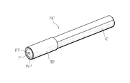
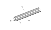
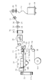
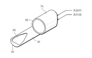
- FIG. 1 It is a perspective view which shows a filter cigarette. It is the perspective view which partially cut away and showed the filter rod for forming the filter of the filter cigarette of FIG. It is the schematic which showed a part of manufacturing machine which manufactures the filter rod of FIG. It is the figure which showed the thread
- the filter cigarette FC includes a cigarette C and a filter F connected to the base end of the cigarette C via a tip paper TP winding.
- the filter F has a fragrance-impregnated yarn FT inside thereof, and the fragrance-impregnated yarn FT contains a fragrance.
- the filter F is obtained by cutting the filter rod FR shown in FIG.
- the filter rod FR includes a filter tow T made of a bundle of acetate fibers, a wrapping material for wrapping the filter tow T in a rod shape, so-called wrapping paper WP, and a fragrance-impregnated yarn FT disposed at the center of the filter tow T. Have.
- FIG. 3 schematically shows a basic configuration of a filter rod FR manufacturing machine, and the manufacturing method of the filter rod FR carried out by this manufacturing machine will become apparent from the following description relating to the manufacturing machine.
- the manufacturing machine includes a tow veil made of acetate fibers, that is, a band-shaped filter tow T, and the filter tow T forms a pile 12 on the carriage 10.
- a transfer path 16 of the filter tow T extends from the pile 12 toward the toe convergence section 14.
- the ring guide 18, the first banding jet 20, and the second banding jet 22 extend from the pile 12 side of the filter tow T to the transfer path 16.
- the pre-tension roll 24, the blooming roll 26, the third banding jet 28, the plasticizer addition device 30 and the transfer roll 32 are sequentially arranged.
- the first to third banding jets 20, 22, and 28 spray compressed air on the filter tow T, and the blowing of the compressed air here releases the crimp of the acetate fiber and opens the filter tow T.
- the pretension roll 24 applies a predetermined tension to the filter tow T, and the blooming roll 26 stretches the filter tow T between the pretension roll 24.
- the adding device 30 uniformly applies liquid triacetin as a plasticizer to the filter tow T. Thereafter, the filter tow T is transferred from the transfer roll 32 to the tow converging section 14.
- the toe convergence section 14 includes a trumpet jet 34 and a trumpet guide 36, and these trumpet jet 34 and trumpet guide 36 are sequentially arranged from the transfer roll 32 side and are adjacent to each other.
- the trumpet jet 34 generates a flow of compressed air toward the trumpet guide 36 therein, and this compressed air flow causes the filter tow T transferred from the transfer roll 32 in the trumpet jet 34 to converge in a cylindrical shape (tow). A converging step), it is guided into the trumpet guide 36. Thereafter, the cylindrical filter tow T that has entered the trumpet guide 36 is once expanded in the radial direction and then transferred toward the wrapping section 38.
- the wrapping section 38 includes a forming bed 40, which extends in the horizontal direction and has a starting end 40a located near the trumpet guide 36 and a terminal end 40b remote from the trumpet guide 36.
- Forming grooves (not shown) are formed on the upper surface of the forming bed 40, and the forming grooves extend from the start end 40a to the end end 40b.
- the forming groove is flat at the start end 40a, the depth of the forming groove gradually increases toward the end 40b, while the width of the forming groove gradually decreases toward the end 40b.
- the forming groove has a semicircular cross section at the end 40b.
- a part of the garniture tape 42 is disposed in the molding groove.
- the garniture tape 42 has an endless shape, and is wound around the drive drum 44 at a predetermined wrapping angle below the forming bed 40 and is guided by a plurality of guide rollers 46. As is apparent from FIG. 3, one of the guide rollers 46 is disposed immediately below the trumpet guide 36.
- the drive drum 44 is rotated, the part of the signature tape 42 travels on the forming groove of the forming bed 40 from the start end 40a to the end end 40b of the forming bed 40.
- the paper web PW is superimposed on the signature tape 42, and the paper web PW is guided from the web roll WR onto the signature tape 42 via a plurality of guide rollers 48.
- One of these guide rollers 48 is disposed immediately below the trumpet guide 36 and adjacent to the guide roller 46 described above.
- spray guns 50 and 52 are arranged in the supply path of the paper web PW. The spray gun 52 applies rail glue to the center when viewed in the width direction of the paper web PW, while the spray gun 52 applies wrap glue to one side edge of the paper web PW.
- the filter tow T that has passed through the trumpet guide 36 is superposed on the paper web PW at the joining end MP defined in front of the starting end 40a or the starting end 40a of the forming bed 40, and is adhered to the paper web PW with rail glue. Thereafter, the paper web PW and the filter tow T travel along the molding groove on the molding bed 40 together with the signature tape 42.
- the tongue 54, the former 56, the heater 58, and the cooler 60 are sequentially arranged immediately above the forming bed 40 from the start end 40a side.
- the tongue 54 squeezes the filter tow T from above (squeezing process) and cooperates with the molding groove of the molding bed 40 to rod the filter tow T. Compress to shape.
- the garniture tape 42 and the paper web PW are bent into a U shape so as to wrap the filter tow T from below along the forming groove.
- the tongue 54 defines a compression molding passage in cooperation with the molding groove of the molding bed 40, and this compression molding passage has a ceiling surface formed by the tongue 54, and this ceiling surface has a molding groove. It has a shape that looks downward. Therefore, at the end 40b of the forming bed 40, that is, at the end of the compression molding passage, the compression molding passage has a circular cross section.
- both side edges of the paper web PW are sequentially bent toward the filter toe T via the signature tape 42. . Therefore, both side edges of the paper web PW are overlapped with each other on the filter tow T, and are bonded to each other with the above-described wrap glue to form a wrap portion.
- the filter tow T is completely wrapped by the paper web PW (lapping process), and the tow rod TR is formed.
- the toe rod TR is firmly adhered to the lap portion.
- a cutting device 70 is disposed immediately downstream of the wrapping section 38, and the tow rod TR passes through the cutting device 70. At this time, the cutting device 70 cuts the toe rod TR for each predetermined length to form individual filter rods FR (cutting step).
- the filter rod FR formed in this way is received by the receiver 72 from the cutting device 70, and thereafter transferred toward a filter cigarette manufacturing machine, so-called a filter mounting machine.
- the filter rod FR is cut by the filter mounting machine, and a double filter having a length twice that of the filter F is formed.
- the double filter is disposed between two cigarettes C, and the cigarette and the double filter are connected by winding the tip paper to form a double filter cigarette. After this, the double filter cigarette is cut into individual filter cigarettes.
- the above-described filter rod FR manufacturing machine further includes a yarn supplying device 74 for incorporating the fragrance-impregnated yarn FT into the tow rod TR. Details of the yarn supplying device 74 are shown in FIG. 4. Is shown in The yarn supply device 74 includes a yarn delivery nozzle 76.
- the yarn delivery nozzle 76 is formed of a pipe member, and extends from the outside of the tow converging section 14 to the wrapping section 38 through the inside of the tow converging section 14, for example.
- the yarn delivery nozzle 76 passes through the trumpet jet 34 and the trumpet guide 36, and has both ends, that is, an inlet end 78 and a yarn delivery end (yarn delivery position) 80.
- the inlet end 78 is positioned outside the trumpet jet 34, while the yarn delivery end 80 is disposed downstream of the above-described merging position MP as viewed in the transfer direction of the filter tow T.
- the yarn sending end 80 enters the tongue 54 and opens toward the downstream as viewed in the transfer direction of the filter tow T.
- the yarn delivery end 80 is positioned on the axis.
- the yarn sending nozzle 76 receives the yarn member S at the inlet end 78, guides the received yarn member S toward the yarn sending end 80, and sends the yarn member S from the yarn sending end 80 into the tongue 54 (yarn sending step).
- the yarn member S is supplied from the yarn supply source 82 and guided to the inlet end 78 of the yarn delivery nozzle 76.
- the yarn supply source 82 is a yarn reel around which the yarn member S is wound, and a feed that supplies the yarn member S from the yarn reel to the yarn delivery nozzle 76 along the guide path.
- 4 includes one guide roller 84 that defines a guide path, and this guide roller 84 is disposed in the vicinity of the inlet end 78.
- the yarn supply device 74 further includes a liquid supply nozzle 86.
- the liquid supply nozzle 86 is also formed from a pipe member and extends along the yarn delivery nozzle 76. That is, the liquid supply nozzle 86 also passes through the trumpet jet 34 and the trumpet guide 36.
- the liquid supply nozzle 86 is positioned immediately below the yarn delivery nozzle 76 and has a tip positioned in the tongue 54, that is, a liquid discharge port (liquid discharge position) 88.
- the liquid discharge port 88 opens upward from the yarn delivery end 80. Therefore, the liquid discharge port 88 is located immediately below the yarn member S delivered from the yarn delivery end 80 and opens toward the lower surface of the yarn member S.
- the tip of the liquid supply nozzle 86 is formed as a closed end 90, and the liquid discharge port 88 has an upper portion of the liquid supply nozzle 86 extending from the closed end 90 over a predetermined length. It is formed by cutting diagonally. It should be noted here that the lower part of the closed end 90 is left.
- the liquid supply nozzle 86 also protrudes from the trumpet jet 34 and is integrally supported by the common holder plate 92 together with the yarn delivery nozzle 76.
- the liquid supply nozzle 86 and the yarn delivery nozzle 76 are integrally supported by the holder plate 92 as described above, the liquid supply nozzle 86 and the yarn delivery nozzle 76 are respectively attached to the holder plate 92 at these predetermined positions.
- the positions of the liquid discharge port 88 and the yarn delivery end 80 in the tongue 54 and the relative position between the yarn delivery end 80 and the liquid delivery outlet 88 are automatically determined. Therefore, it is not necessary to adjust the position of the subsequent yarn delivery end 80 and the liquid delivery outlet 88, and variations in the addition of the fragrance liquid can be reduced and the productivity can be improved.
- the liquid supply nozzle 86 is connected to a liquid supply pipe 94 by a holder plate 92, and the liquid supply pipe 94 extends toward the liquid supply source 96 and is connected to the liquid supply source 96.
- the liquid supply source 96 can quantitatively supply the fragrance liquid to the liquid supply nozzle 86 through the liquid supply pipe 94.
- the liquid supply source 96 includes a liquid tank that stores the fragrance liquid, a quantitative pump that supplies the fragrance liquid from the liquid tank, and the like.
- the fragrance liquid contains propylene glycol (PG) as a solvent and menthol (M) as a fragrance dissolved in this propylene glycol.
- the yarn member S is fed from the yarn delivery end 80 of the yarn delivery nozzle 76 toward the center of the filter tow T that has entered the tongue 54 (during the narrowing process) (yarn).
- the fragrance liquid is discharged obliquely upward from the liquid discharge port 88 of the liquid supply nozzle 86, that is, toward the thread member S (liquid discharge process).
- the fragrance liquid discharged in this manner is applied to the thread member S and impregnated in the thread member S in the process of forming the toe rod TR. Therefore, the thread member S becomes the fragrance-impregnated thread FT described above.
- the tow rod TR that is, the filter rod FR formed from the tow rod TR has the fragrance-impregnated yarn FT at its center.
- the thread member S to which the fragrance liquid is applied that is, the fragrance impregnated yarn FT is thereafter applied. Is surrounded by the filter tow T and contacts with the filter tow T, but does not come into contact with mechanical elements such as the yarn delivery nozzle 76, the surrounding tongue 54, the garniture tape 42 and the forming bed 40. Therefore, the possibility that the fragrance liquid once impregnated in the fragrance-impregnated yarn FT exudes from the fragrance-impregnated yarn FT is low. Further, even if the fragrance liquid oozes out from the fragrance-impregnated yarn FT, the fragrance liquid here is only attached to the filter tow T and does not adhere to the yarn delivery nozzle 76 or the surrounding mechanical elements.
- the discharge amount of the fragrance liquid from the liquid discharge port 88 is constant, the variation of the impregnation amount in the fragrance liquid is effective with respect to the amount of the fragrance liquid impregnated in the fragrance impregnation yarn FT per filter rod FR. Is suppressed.
- the content of the fragrance liquid per filter rod FR is constant.
- the liquid discharge port 88 is opened upward, the liquid discharge port can be operated even when the operation of the manufacturing machine, that is, the supply of the fragrance liquid from the liquid supply source 96 is stopped. From 88, the fragrance liquid does not fall down due to gravity. Therefore, the surrounding machine elements are not contaminated with the fragrance liquid, and the load on cleaning the machine elements can be reduced.
- Table 1 shows the results of measuring the average value of the amount of menthol M contained in the perfume-impregnated yarn FT and the CV value thereof with respect to the filter rods FR of Examples E1 and E2 manufactured by the above-described manufacturing machine. Indicates.
- Qo and M amounts indicate the target content and actual impregnation amount of menthol M per one perfume impregnated yarn FT.
- Table 1 also shows similar measurement results regarding the filter rods of Comparative Examples C1 to C3 manufactured by the manufacturing machine of Patent Document 1. Note that the difference between the examples E1 and E2 and the difference between the comparative examples C1 to C3 represent the difference in manufacturing date and time.
- FIG. 7 shows the CV value of menthol M in Table 1 as a bar graph.
- the CV values of Examples E1 and E2 are significantly reduced as compared with the CV values of Comparative Examples C1 to C3. This means that the amount of menthol M contained in one filter rod FR, that is, one filter F, is stabilized, and it becomes possible to manufacture a high-quality filter cigarette FC.
- FIG. 8 shows the filter rod FR of Examples E3 and E4 manufactured by changing the target impregnation amount Qo of the fragrance liquid to 0.056 g / piece, and the CV value of menthol M in these Examples E3 and E4 is shown. Show. As is clear from FIG. 8, if the target impregnation amount Qo of menthol M is increased, the manufacturing machine of the present embodiment can further reduce the CV value of menthol M.
- the present invention is not limited to the manufacturing machine and the manufacturing method of the above-described embodiment, and various modifications are possible.
- the liquid discharge port 88 of the liquid supply nozzle 86 may be opened vertically and upward, or may be opened toward the side surface of the thread member S.
- a plurality of liquid supply nozzles 86 may be provided.
- both the yarn delivery nozzle 76 and the liquid supply nozzle 86 extend through the trumpet jet 34 and the trumpet guide 36 and into the tongue 54, but at least the yarn delivery nozzle 76 is in the transfer direction of the filter tow T.
- the additive liquid impregnated in the thread member may contain other fragrance in addition to menthol, and the solvent is not limited to propylene glycol.
- the blending ratio of menthol and solvent may be 9: 1 to 5: 5.
Landscapes
- Cigarettes, Filters, And Manufacturing Of Filters (AREA)
Abstract
L'invention concerne une machine de fabrication pour mettre en œuvre ce procédé de fabrication de bâtonnets-filtres qui comprend : une buse (76) d'alimentation en fibres qui est équipée d'une extrémité (80) d'alimentation en fibres à un endroit en aval d'une position de fusion (MP) où une mèche filtrante (T) et une feuille de papier continue (PW) se fondent dans un processus de formation d'un bâtonnet (TR) de mèche à partir de la mèche filtrante (T) et de la feuille de papier continue (PW) et qui fournit un élément de fibre (S) à partir de ladite extrémité (80) d'alimentation en fibres dans la mèche filtrante (T) dans une languette (54) ; et une buse (86) d'alimentation en liquide, qui est équipée d'un orifice (88) de déversement de liquide situé en aval de l'extrémité (80) d'alimentation en fibres et déverse un liquide parfumé (L) à partir dudit orifice (88) de déversement de liquide vers l'élément de fibre (S) pour imprégner celui-ci dudit liquide.
Priority Applications (3)
| Application Number | Priority Date | Filing Date | Title |
|---|---|---|---|
| PCT/JP2012/083609 WO2014102926A1 (fr) | 2012-12-26 | 2012-12-26 | Machine de fabrication de bâtonnets-filtres et procédé de fabrication de bâtonnets-filtres |
| JP2014553933A JP5888800B2 (ja) | 2012-12-26 | 2012-12-26 | フィルタロッドの製造機及びフィルタロッドの製造方法 |
| EP12890930.6A EP2910133B1 (fr) | 2012-12-26 | 2012-12-26 | Machine de fabrication de bâtonnets-filtres et procédé de fabrication de bâtonnets-filtres |
Applications Claiming Priority (1)
| Application Number | Priority Date | Filing Date | Title |
|---|---|---|---|
| PCT/JP2012/083609 WO2014102926A1 (fr) | 2012-12-26 | 2012-12-26 | Machine de fabrication de bâtonnets-filtres et procédé de fabrication de bâtonnets-filtres |
Publications (1)
| Publication Number | Publication Date |
|---|---|
| WO2014102926A1 true WO2014102926A1 (fr) | 2014-07-03 |
Family
ID=51020085
Family Applications (1)
| Application Number | Title | Priority Date | Filing Date |
|---|---|---|---|
| PCT/JP2012/083609 Ceased WO2014102926A1 (fr) | 2012-12-26 | 2012-12-26 | Machine de fabrication de bâtonnets-filtres et procédé de fabrication de bâtonnets-filtres |
Country Status (3)
| Country | Link |
|---|---|
| EP (1) | EP2910133B1 (fr) |
| JP (1) | JP5888800B2 (fr) |
| WO (1) | WO2014102926A1 (fr) |
Cited By (3)
| Publication number | Priority date | Publication date | Assignee | Title |
|---|---|---|---|---|
| DE102015201781A1 (de) * | 2015-02-02 | 2016-08-04 | Hauni Maschinenbau Ag | Verfahren und Vorrichtung zum Herstellen von Filtern der Tabak verarbeitenden Industrie |
| JP2022517157A (ja) * | 2019-12-19 | 2022-03-07 | ケーティー アンド ジー コーポレイション | チューブフィルター製造装置およびチューブフィルターの製造方法 |
| CN116249458A (zh) * | 2020-10-09 | 2023-06-09 | 菲利普莫里斯生产公司 | 在将片材材料成形为包括可加热感受器的条时施加添加剂 |
Families Citing this family (4)
| Publication number | Priority date | Publication date | Assignee | Title |
|---|---|---|---|---|
| CN105595415A (zh) * | 2016-01-15 | 2016-05-25 | 红云红河烟草(集团)有限责任公司 | 一种利用荔枝花蜜制备蜜香卷烟香线的方法 |
| CN109793276B (zh) * | 2019-03-20 | 2021-02-19 | 红云红河烟草(集团)有限责任公司 | 一种导丝舌凝胶加注装置 |
| KR102533111B1 (ko) * | 2020-02-17 | 2023-05-16 | 주식회사 케이티앤지 | 가향처리된 튜브필터를 포함하는 흡연물품 및 그의 제조 방법 |
| JP2023547367A (ja) * | 2020-10-26 | 2023-11-10 | フィリップ・モーリス・プロダクツ・ソシエテ・アノニム | エアロゾル発生物品の構成要素を製造するための方法および機器 |
Citations (4)
| Publication number | Priority date | Publication date | Assignee | Title |
|---|---|---|---|---|
| JPS5558084A (en) | 1978-04-21 | 1980-04-30 | Cigarette Components Ltd | Tobacco filter and producing apparatus thereof |
| JPS59227286A (ja) * | 1983-06-02 | 1984-12-20 | ア−ル・ジエイ・レノルズ・タバコ・カンパニ− | タバコ煙フイルタ−およびその製造方法および装置 |
| JP2005521399A (ja) * | 2002-03-29 | 2005-07-21 | フィリップ・モーリス・プロダクツ・ソシエテ・アノニム | 中央に位置した香味付き素子を持つ紙巻きたばこフィルターを作るための方法と装置 |
| JP2008035861A (ja) * | 2006-08-04 | 2008-02-21 | Philip Morris Products Sa | 多重香味強化をもたらす多成分フィルタ |
Family Cites Families (3)
| Publication number | Priority date | Publication date | Assignee | Title |
|---|---|---|---|---|
| GB0714530D0 (en) * | 2007-07-25 | 2007-09-05 | British American Tobacco Co | New apparatus and method |
| GB0905210D0 (en) * | 2009-03-26 | 2009-05-13 | British American Tobacco Co | Rod for a smoking article and method and apparatus for manufacture |
| WO2012164645A1 (fr) * | 2011-05-27 | 2012-12-06 | 日本たばこ産業株式会社 | Dispositif de fabrication de filtre, procédé de fabrication de filtre et filtre |
-
2012
- 2012-12-26 JP JP2014553933A patent/JP5888800B2/ja not_active Expired - Fee Related
- 2012-12-26 WO PCT/JP2012/083609 patent/WO2014102926A1/fr not_active Ceased
- 2012-12-26 EP EP12890930.6A patent/EP2910133B1/fr active Active
Patent Citations (4)
| Publication number | Priority date | Publication date | Assignee | Title |
|---|---|---|---|---|
| JPS5558084A (en) | 1978-04-21 | 1980-04-30 | Cigarette Components Ltd | Tobacco filter and producing apparatus thereof |
| JPS59227286A (ja) * | 1983-06-02 | 1984-12-20 | ア−ル・ジエイ・レノルズ・タバコ・カンパニ− | タバコ煙フイルタ−およびその製造方法および装置 |
| JP2005521399A (ja) * | 2002-03-29 | 2005-07-21 | フィリップ・モーリス・プロダクツ・ソシエテ・アノニム | 中央に位置した香味付き素子を持つ紙巻きたばこフィルターを作るための方法と装置 |
| JP2008035861A (ja) * | 2006-08-04 | 2008-02-21 | Philip Morris Products Sa | 多重香味強化をもたらす多成分フィルタ |
Cited By (7)
| Publication number | Priority date | Publication date | Assignee | Title |
|---|---|---|---|---|
| DE102015201781A1 (de) * | 2015-02-02 | 2016-08-04 | Hauni Maschinenbau Ag | Verfahren und Vorrichtung zum Herstellen von Filtern der Tabak verarbeitenden Industrie |
| EP3050442B1 (fr) * | 2015-02-02 | 2021-04-28 | Hauni Maschinenbau GmbH | Procede et dispositif de fabrication de filtres de l'industrie de traitement du tabac |
| JP2022517157A (ja) * | 2019-12-19 | 2022-03-07 | ケーティー アンド ジー コーポレイション | チューブフィルター製造装置およびチューブフィルターの製造方法 |
| JP7063500B2 (ja) | 2019-12-19 | 2022-05-09 | ケーティー アンド ジー コーポレイション | チューブフィルター製造装置およびチューブフィルターの製造方法 |
| CN116249458A (zh) * | 2020-10-09 | 2023-06-09 | 菲利普莫里斯生产公司 | 在将片材材料成形为包括可加热感受器的条时施加添加剂 |
| JP2023546029A (ja) * | 2020-10-09 | 2023-11-01 | フィリップ・モーリス・プロダクツ・ソシエテ・アノニム | シート材料を加熱可能なサセプタを組み込むロッドに成形する際の添加物の適用 |
| JP7830447B2 (ja) | 2020-10-09 | 2026-03-16 | フィリップ・モーリス・プロダクツ・ソシエテ・アノニム | シート材料を加熱可能なサセプタを組み込むロッドに成形する際の添加物の適用 |
Also Published As
| Publication number | Publication date |
|---|---|
| EP2910133A4 (fr) | 2016-06-15 |
| EP2910133B1 (fr) | 2020-03-04 |
| EP2910133A1 (fr) | 2015-08-26 |
| JP5888800B2 (ja) | 2016-03-22 |
| JPWO2014102926A1 (ja) | 2017-01-12 |
Similar Documents
| Publication | Publication Date | Title |
|---|---|---|
| JP5888800B2 (ja) | フィルタロッドの製造機及びフィルタロッドの製造方法 | |
| JP5388249B2 (ja) | フィルタ製造機 | |
| JP5487357B2 (ja) | シガレットフィルタの製造装置およびシガレットフィルタの製造方法 | |
| KR102072382B1 (ko) | 권축 시트 재료의 연속 웨브를 공급하기 위한 장치 및 방법 | |
| US6908421B2 (en) | Filter manufacturing machine | |
| EP3254570B1 (fr) | Procédé de production de cigarettes à filtre, filtre et cigarette à filtre | |
| JP4222524B2 (ja) | フィルタロッド製造機 | |
| JPWO2002017738A1 (ja) | フィルタ製造機 | |
| KR102022302B1 (ko) | 담배용 필터의 제조장치 | |
| JP5640090B2 (ja) | フィルタ製造装置、フィルタ製造方法、およびフィルタ | |
| JP6767358B2 (ja) | フィルタロッド形成方法及び装置 | |
| JP6359117B2 (ja) | トウバンドの製造方法及びトウバンド製造装置 | |
| KR20180000349A (ko) | 토우 절단기 | |
| KR20180044351A (ko) | 필터 로드 건조 방법 | |
| CN117120677B (zh) | 短纤维的制造方法、无纺布的制造方法、短纤维制造装置以及无纺布制造装置 | |
| WO2013175613A1 (fr) | Machine de fabrication et procédé de fabrication |
Legal Events
| Date | Code | Title | Description |
|---|---|---|---|
| 121 | Ep: the epo has been informed by wipo that ep was designated in this application |
Ref document number: 12890930 Country of ref document: EP Kind code of ref document: A1 |
|
| ENP | Entry into the national phase |
Ref document number: 2014553933 Country of ref document: JP Kind code of ref document: A |
|
| WWE | Wipo information: entry into national phase |
Ref document number: 2012890930 Country of ref document: EP |
|
| NENP | Non-entry into the national phase |
Ref country code: DE |