WO2014103030A1 - Procédé et dispositif pour commander un dispositif à phase variable - Google Patents
Procédé et dispositif pour commander un dispositif à phase variable Download PDFInfo
- Publication number
- WO2014103030A1 WO2014103030A1 PCT/JP2012/084127 JP2012084127W WO2014103030A1 WO 2014103030 A1 WO2014103030 A1 WO 2014103030A1 JP 2012084127 W JP2012084127 W JP 2012084127W WO 2014103030 A1 WO2014103030 A1 WO 2014103030A1
- Authority
- WO
- WIPO (PCT)
- Prior art keywords
- relative angle
- value
- electromagnetic clutch
- phase
- phase variable
- Prior art date
- Legal status (The legal status is an assumption and is not a legal conclusion. Google has not performed a legal analysis and makes no representation as to the accuracy of the status listed.)
- Ceased
Links
Images



Classifications
-
- F—MECHANICAL ENGINEERING; LIGHTING; HEATING; WEAPONS; BLASTING
- F01—MACHINES OR ENGINES IN GENERAL; ENGINE PLANTS IN GENERAL; STEAM ENGINES
- F01L—CYCLICALLY OPERATING VALVES FOR MACHINES OR ENGINES
- F01L1/00—Valve-gear or valve arrangements, e.g. lift-valve gear
- F01L1/34—Valve-gear or valve arrangements, e.g. lift-valve gear characterised by the provision of means for changing the timing of the valves without changing the duration of opening and without affecting the magnitude of the valve lift
- F01L1/344—Valve-gear or valve arrangements, e.g. lift-valve gear characterised by the provision of means for changing the timing of the valves without changing the duration of opening and without affecting the magnitude of the valve lift changing the angular relationship between crankshaft and camshaft, e.g. using helicoidal gear
-
- F—MECHANICAL ENGINEERING; LIGHTING; HEATING; WEAPONS; BLASTING
- F02—COMBUSTION ENGINES; HOT-GAS OR COMBUSTION-PRODUCT ENGINE PLANTS
- F02D—CONTROLLING COMBUSTION ENGINES
- F02D13/00—Controlling the engine output power by varying inlet or exhaust valve operating characteristics, e.g. timing
- F02D13/02—Controlling the engine output power by varying inlet or exhaust valve operating characteristics, e.g. timing during engine operation
- F02D13/0223—Variable control of the intake valves only
- F02D13/0234—Variable control of the intake valves only changing the valve timing only
- F02D13/0238—Variable control of the intake valves only changing the valve timing only by shifting the phase, i.e. the opening periods of the valves are constant
-
- F—MECHANICAL ENGINEERING; LIGHTING; HEATING; WEAPONS; BLASTING
- F02—COMBUSTION ENGINES; HOT-GAS OR COMBUSTION-PRODUCT ENGINE PLANTS
- F02D—CONTROLLING COMBUSTION ENGINES
- F02D35/00—Controlling engines, dependent on conditions exterior or interior to engines, not otherwise provided for
- F02D35/02—Controlling engines, dependent on conditions exterior or interior to engines, not otherwise provided for on interior conditions
- F02D35/028—Controlling engines, dependent on conditions exterior or interior to engines, not otherwise provided for on interior conditions by determining the combustion timing or phasing
-
- F—MECHANICAL ENGINEERING; LIGHTING; HEATING; WEAPONS; BLASTING
- F02—COMBUSTION ENGINES; HOT-GAS OR COMBUSTION-PRODUCT ENGINE PLANTS
- F02D—CONTROLLING COMBUSTION ENGINES
- F02D41/00—Electrical control of supply of combustible mixture or its constituents
- F02D41/0002—Controlling intake air
-
- F—MECHANICAL ENGINEERING; LIGHTING; HEATING; WEAPONS; BLASTING
- F02—COMBUSTION ENGINES; HOT-GAS OR COMBUSTION-PRODUCT ENGINE PLANTS
- F02D—CONTROLLING COMBUSTION ENGINES
- F02D41/00—Electrical control of supply of combustible mixture or its constituents
- F02D41/02—Circuit arrangements for generating control signals
- F02D41/14—Introducing closed-loop corrections
- F02D41/1401—Introducing closed-loop corrections characterised by the control or regulation method
- F02D41/1403—Sliding mode control
-
- G—PHYSICS
- G05—CONTROLLING; REGULATING
- G05B—CONTROL OR REGULATING SYSTEMS IN GENERAL; FUNCTIONAL ELEMENTS OF SUCH SYSTEMS; MONITORING OR TESTING ARRANGEMENTS FOR SUCH SYSTEMS OR ELEMENTS
- G05B13/00—Adaptive control systems, i.e. systems automatically adjusting themselves to have a performance which is optimum according to some preassigned criterion
- G05B13/02—Adaptive control systems, i.e. systems automatically adjusting themselves to have a performance which is optimum according to some preassigned criterion electric
- G05B13/0205—Adaptive control systems, i.e. systems automatically adjusting themselves to have a performance which is optimum according to some preassigned criterion electric not using a model or a simulator of the controlled system
- G05B13/0255—Adaptive control systems, i.e. systems automatically adjusting themselves to have a performance which is optimum according to some preassigned criterion electric not using a model or a simulator of the controlled system the criterion being a time-optimal performance criterion
-
- G—PHYSICS
- G05—CONTROLLING; REGULATING
- G05B—CONTROL OR REGULATING SYSTEMS IN GENERAL; FUNCTIONAL ELEMENTS OF SUCH SYSTEMS; MONITORING OR TESTING ARRANGEMENTS FOR SUCH SYSTEMS OR ELEMENTS
- G05B13/00—Adaptive control systems, i.e. systems automatically adjusting themselves to have a performance which is optimum according to some preassigned criterion
- G05B13/02—Adaptive control systems, i.e. systems automatically adjusting themselves to have a performance which is optimum according to some preassigned criterion electric
- G05B13/0205—Adaptive control systems, i.e. systems automatically adjusting themselves to have a performance which is optimum according to some preassigned criterion electric not using a model or a simulator of the controlled system
- G05B13/026—Adaptive control systems, i.e. systems automatically adjusting themselves to have a performance which is optimum according to some preassigned criterion electric not using a model or a simulator of the controlled system using a predictor
-
- G—PHYSICS
- G05—CONTROLLING; REGULATING
- G05B—CONTROL OR REGULATING SYSTEMS IN GENERAL; FUNCTIONAL ELEMENTS OF SUCH SYSTEMS; MONITORING OR TESTING ARRANGEMENTS FOR SUCH SYSTEMS OR ELEMENTS
- G05B19/00—Program-control systems
- G05B19/02—Program-control systems electric
- G05B19/18—Numerical control [NC], i.e. automatically operating machines, in particular machine tools, e.g. in a manufacturing environment, so as to execute positioning, movement or co-ordinated operations by means of program data in numerical form
- G05B19/19—Numerical control [NC], i.e. automatically operating machines, in particular machine tools, e.g. in a manufacturing environment, so as to execute positioning, movement or co-ordinated operations by means of program data in numerical form characterised by positioning or contouring control systems, e.g. to control position from one programmed point to another or to control movement along a programmed continuous path
-
- F—MECHANICAL ENGINEERING; LIGHTING; HEATING; WEAPONS; BLASTING
- F01—MACHINES OR ENGINES IN GENERAL; ENGINE PLANTS IN GENERAL; STEAM ENGINES
- F01L—CYCLICALLY OPERATING VALVES FOR MACHINES OR ENGINES
- F01L1/00—Valve-gear or valve arrangements, e.g. lift-valve gear
- F01L1/02—Valve drive
- F01L1/04—Valve drive by means of cams, camshafts, cam discs, eccentrics or the like
- F01L1/047—Camshafts
- F01L1/053—Camshafts overhead type
- F01L2001/0537—Double overhead camshafts [DOHC]
-
- F—MECHANICAL ENGINEERING; LIGHTING; HEATING; WEAPONS; BLASTING
- F01—MACHINES OR ENGINES IN GENERAL; ENGINE PLANTS IN GENERAL; STEAM ENGINES
- F01L—CYCLICALLY OPERATING VALVES FOR MACHINES OR ENGINES
- F01L1/00—Valve-gear or valve arrangements, e.g. lift-valve gear
- F01L1/34—Valve-gear or valve arrangements, e.g. lift-valve gear characterised by the provision of means for changing the timing of the valves without changing the duration of opening and without affecting the magnitude of the valve lift
- F01L1/344—Valve-gear or valve arrangements, e.g. lift-valve gear characterised by the provision of means for changing the timing of the valves without changing the duration of opening and without affecting the magnitude of the valve lift changing the angular relationship between crankshaft and camshaft, e.g. using helicoidal gear
- F01L1/3442—Valve-gear or valve arrangements, e.g. lift-valve gear characterised by the provision of means for changing the timing of the valves without changing the duration of opening and without affecting the magnitude of the valve lift changing the angular relationship between crankshaft and camshaft, e.g. using helicoidal gear using hydraulic chambers with variable volume to transmit the rotating force
- F01L2001/3445—Details relating to the hydraulic means for changing the angular relationship
- F01L2001/34483—Phaser return springs
-
- F—MECHANICAL ENGINEERING; LIGHTING; HEATING; WEAPONS; BLASTING
- F01—MACHINES OR ENGINES IN GENERAL; ENGINE PLANTS IN GENERAL; STEAM ENGINES
- F01L—CYCLICALLY OPERATING VALVES FOR MACHINES OR ENGINES
- F01L1/00—Valve-gear or valve arrangements, e.g. lift-valve gear
- F01L1/34—Valve-gear or valve arrangements, e.g. lift-valve gear characterised by the provision of means for changing the timing of the valves without changing the duration of opening and without affecting the magnitude of the valve lift
- F01L1/344—Valve-gear or valve arrangements, e.g. lift-valve gear characterised by the provision of means for changing the timing of the valves without changing the duration of opening and without affecting the magnitude of the valve lift changing the angular relationship between crankshaft and camshaft, e.g. using helicoidal gear
- F01L1/352—Valve-gear or valve arrangements, e.g. lift-valve gear characterised by the provision of means for changing the timing of the valves without changing the duration of opening and without affecting the magnitude of the valve lift changing the angular relationship between crankshaft and camshaft, e.g. using helicoidal gear using bevel or epicyclic gear
- F01L2001/3522—Valve-gear or valve arrangements, e.g. lift-valve gear characterised by the provision of means for changing the timing of the valves without changing the duration of opening and without affecting the magnitude of the valve lift changing the angular relationship between crankshaft and camshaft, e.g. using helicoidal gear using bevel or epicyclic gear with electromagnetic brake
-
- F—MECHANICAL ENGINEERING; LIGHTING; HEATING; WEAPONS; BLASTING
- F01—MACHINES OR ENGINES IN GENERAL; ENGINE PLANTS IN GENERAL; STEAM ENGINES
- F01L—CYCLICALLY OPERATING VALVES FOR MACHINES OR ENGINES
- F01L2250/00—Camshaft drives characterised by their transmission means
- F01L2250/02—Camshaft drives characterised by their transmission means the camshaft being driven by chains
-
- F—MECHANICAL ENGINEERING; LIGHTING; HEATING; WEAPONS; BLASTING
- F01—MACHINES OR ENGINES IN GENERAL; ENGINE PLANTS IN GENERAL; STEAM ENGINES
- F01L—CYCLICALLY OPERATING VALVES FOR MACHINES OR ENGINES
- F01L2800/00—Methods of operation using a variable valve timing mechanism
-
- F—MECHANICAL ENGINEERING; LIGHTING; HEATING; WEAPONS; BLASTING
- F02—COMBUSTION ENGINES; HOT-GAS OR COMBUSTION-PRODUCT ENGINE PLANTS
- F02D—CONTROLLING COMBUSTION ENGINES
- F02D41/00—Electrical control of supply of combustible mixture or its constituents
- F02D41/0002—Controlling intake air
- F02D2041/001—Controlling intake air for engines with variable valve actuation
-
- F—MECHANICAL ENGINEERING; LIGHTING; HEATING; WEAPONS; BLASTING
- F02—COMBUSTION ENGINES; HOT-GAS OR COMBUSTION-PRODUCT ENGINE PLANTS
- F02D—CONTROLLING COMBUSTION ENGINES
- F02D41/00—Electrical control of supply of combustible mixture or its constituents
- F02D41/02—Circuit arrangements for generating control signals
- F02D41/14—Introducing closed-loop corrections
- F02D41/1401—Introducing closed-loop corrections characterised by the control or regulation method
- F02D2041/1412—Introducing closed-loop corrections characterised by the control or regulation method using a predictive controller
-
- F—MECHANICAL ENGINEERING; LIGHTING; HEATING; WEAPONS; BLASTING
- F02—COMBUSTION ENGINES; HOT-GAS OR COMBUSTION-PRODUCT ENGINE PLANTS
- F02D—CONTROLLING COMBUSTION ENGINES
- F02D41/00—Electrical control of supply of combustible mixture or its constituents
- F02D41/02—Circuit arrangements for generating control signals
- F02D41/14—Introducing closed-loop corrections
- F02D41/1401—Introducing closed-loop corrections characterised by the control or regulation method
- F02D2041/1413—Controller structures or design
- F02D2041/1415—Controller structures or design using a state feedback or a state space representation
- F02D2041/1417—Kalman filter
-
- G—PHYSICS
- G05—CONTROLLING; REGULATING
- G05B—CONTROL OR REGULATING SYSTEMS IN GENERAL; FUNCTIONAL ELEMENTS OF SUCH SYSTEMS; MONITORING OR TESTING ARRANGEMENTS FOR SUCH SYSTEMS OR ELEMENTS
- G05B2219/00—Program-control systems
- G05B2219/30—Nc systems
- G05B2219/41—Servomotor, servo controller till figures
- G05B2219/41259—Coupling, clutch
-
- G—PHYSICS
- G05—CONTROLLING; REGULATING
- G05B—CONTROL OR REGULATING SYSTEMS IN GENERAL; FUNCTIONAL ELEMENTS OF SUCH SYSTEMS; MONITORING OR TESTING ARRANGEMENTS FOR SUCH SYSTEMS OR ELEMENTS
- G05B2219/00—Program-control systems
- G05B2219/30—Nc systems
- G05B2219/41—Servomotor, servo controller till figures
- G05B2219/41385—Observe position from encoder, estimate speed, position with kalman filter
-
- G—PHYSICS
- G05—CONTROLLING; REGULATING
- G05B—CONTROL OR REGULATING SYSTEMS IN GENERAL; FUNCTIONAL ELEMENTS OF SUCH SYSTEMS; MONITORING OR TESTING ARRANGEMENTS FOR SUCH SYSTEMS OR ELEMENTS
- G05B2219/00—Program-control systems
- G05B2219/30—Nc systems
- G05B2219/42—Servomotor, servo controller kind till VSS
- G05B2219/42249—Relative positioning
-
- G—PHYSICS
- G05—CONTROLLING; REGULATING
- G05B—CONTROL OR REGULATING SYSTEMS IN GENERAL; FUNCTIONAL ELEMENTS OF SUCH SYSTEMS; MONITORING OR TESTING ARRANGEMENTS FOR SUCH SYSTEMS OR ELEMENTS
- G05B2219/00—Program-control systems
- G05B2219/30—Nc systems
- G05B2219/42—Servomotor, servo controller kind till VSS
- G05B2219/42352—Sliding mode controller SMC, select other gain
-
- G—PHYSICS
- G05—CONTROLLING; REGULATING
- G05B—CONTROL OR REGULATING SYSTEMS IN GENERAL; FUNCTIONAL ELEMENTS OF SUCH SYSTEMS; MONITORING OR TESTING ARRANGEMENTS FOR SUCH SYSTEMS OR ELEMENTS
- G05B2219/00—Program-control systems
- G05B2219/30—Nc systems
- G05B2219/45—Nc applications
- G05B2219/45006—Valves
-
- Y—GENERAL TAGGING OF NEW TECHNOLOGICAL DEVELOPMENTS; GENERAL TAGGING OF CROSS-SECTIONAL TECHNOLOGIES SPANNING OVER SEVERAL SECTIONS OF THE IPC; TECHNICAL SUBJECTS COVERED BY FORMER USPC CROSS-REFERENCE ART COLLECTIONS [XRACs] AND DIGESTS
- Y02—TECHNOLOGIES OR APPLICATIONS FOR MITIGATION OR ADAPTATION AGAINST CLIMATE CHANGE
- Y02T—CLIMATE CHANGE MITIGATION TECHNOLOGIES RELATED TO TRANSPORTATION
- Y02T10/00—Road transport of goods or passengers
- Y02T10/10—Internal combustion engine [ICE] based vehicles
- Y02T10/12—Improving ICE efficiencies
-
- Y—GENERAL TAGGING OF NEW TECHNOLOGICAL DEVELOPMENTS; GENERAL TAGGING OF CROSS-SECTIONAL TECHNOLOGIES SPANNING OVER SEVERAL SECTIONS OF THE IPC; TECHNICAL SUBJECTS COVERED BY FORMER USPC CROSS-REFERENCE ART COLLECTIONS [XRACs] AND DIGESTS
- Y02—TECHNOLOGIES OR APPLICATIONS FOR MITIGATION OR ADAPTATION AGAINST CLIMATE CHANGE
- Y02T—CLIMATE CHANGE MITIGATION TECHNOLOGIES RELATED TO TRANSPORTATION
- Y02T10/00—Road transport of goods or passengers
- Y02T10/10—Internal combustion engine [ICE] based vehicles
- Y02T10/40—Engine management systems
Definitions
- the present invention relates to a control method and control device for a phase variable device that changes the opening and closing timing of a valve.
- a method of using a phase variable device that changes the opening / closing timing of an engine valve is adopted as a method of demonstrating the engine performance of an automobile over the entire range from low speed to high speed.
- engine performance refers to a variety of things including fuel efficiency, engine responsiveness, low emissions, and idling stability.
- the phase variable device changes the engine speed by changing the phase of the crankshaft and camshaft.
- the optimum valve opening / closing timing can be selected according to the situation, and the engine performance can be dramatically improved.
- Patent Document 1 describes a phase variable device that operates a ring gear of a planetary gear mechanism and a carrier of a planetary gear by two electromagnetic clutches.
- the phase variable device has a main body directly connected to a camshaft. Since the phase variable device is directly connected to the engine, the environment in which it is installed is susceptible to disturbances such as engine temperature, outside air temperature, and vibration. Therefore, the ECU (engine control unit), which is a controller, adopts not only conventional PID control but also sliding mode control with high robustness to perform appropriate control of valve opening / closing timing.
- the valve opening / closing timing control by the ECU is performed according to the rotational speed of the crankshaft.
- the input information to the ECU is reduced, so that the phase variable device
- the response is low and the engine cannot be properly controlled, and the desired engine performance cannot be obtained. Accordingly, it is a problem to be solved by the present invention to provide a control method for a phase variable device and such a control device that allow the phase variable device to obtain sufficient response even in a low rotation range.
- the invention according to claim 1 is a control method of the phase varying device 51 that changes the valve timing of the engine valve by changing the rotational phase of the camshaft 53 with respect to the crankshaft 22 of the internal combustion engine 11.
- the phase varying device 51 includes a drive rotator to which rotation is transmitted from the crankshaft 22, a driven rotator on the camshaft side coaxial with the drive rotator, and a relative angle between these rotators.
- a phase variable mechanism that changes using the clutch 70 and controls the phase variable device 51, and calculates the relative speed at the current step calculated from the rotational speed value of the crankshaft 22 and the rotational speed value of the camshaft 53.
- Relative angle estimated value after one step using the Kalman filter from the angle and the command value of the current step to the electromagnetic clutch 70 A phase control method of the phase variable device 51 that calculates and inputs this as a feedback signal to the sliding mode controller 103 and calculates and outputs a command value after one step to the electromagnetic clutch 70 based on the value of this feedback signal It is.
- the invention according to claim 2 is that the command value to the electromagnetic clutch 70 is an output value from the sliding mode controller 103 and a feedforward controller 111 for setting a target relative angle registered in advance.
- the Kalman filter when the sensor flag from the sensor for detecting the rotation angle of the crankshaft 22 or the camshaft 53 of the internal combustion engine 11 is not set, the Kalman filter is connected to the electromagnetic clutch 70.
- the relative angle estimation value after one step is calculated from only the command value at the current step, and when the sensor flag is set, the Kalman filter applies the relative angle at the current step to the electromagnetic clutch 70.
- the invention according to claim 4 performs system identification of the phase variable device 51 using a Kalman filter from the relative angle in the current step and the command value of the current step to the electromagnetic clutch 70, and this system identification.
- the invention according to claim 5 is a control device for the phase varying device 51 that changes the valve timing of the engine valve by changing the rotational phase of the camshaft 53 with respect to the crankshaft 22 of the internal combustion engine 11.
- the phase varying device 51 includes a drive rotator to which rotation is transmitted from the crankshaft, a driven rotator on the camshaft 53 side coaxial with the drive rotator, and a relative angle between these rotators.
- a phase variable mechanism that changes using the clutch 70 and controls the phase variable device 51, and the control device calculates from the rotational speed value of the crankshaft 22 and the rotational speed value of the camshaft 53.
- a phase control device including a phase variable device estimator 107 that calculates and feeds back an estimated diagonal value, and a sliding mode controller 103 that outputs a command value after one step to the electromagnetic clutch 70. It is.
- the command value to the electromagnetic clutch 70 is an output value from the sliding mode controller 103 and a feedforward controller 111 for setting a target relative angle registered in advance.
- the Kalman filter when the sensor flag from the sensor for detecting the rotation angle of the crankshaft 22 or the camshaft 53 of the internal combustion engine 11 is not set, the Kalman filter is connected to the electromagnetic clutch 70.
- the relative angle estimation value after one step is calculated from only the command value at the current step, and when the sensor flag is set, the Kalman filter applies the relative angle at the current step to the electromagnetic clutch 70.
- a phase variable device estimator 107 that calculates and feeds back the estimated relative angle value after one step using the command value at the current step of claim 7 or 7. It is a control device.
- the invention according to claim 8 performs system identification of the phase variable device 51 using a Kalman filter from the relative angle in the current step and the command value of the current step to the electromagnetic clutch 70, and this system identification
- the Kalman filter is calculated from the relative angle at the current step calculated from the rotational speed values of the crankshaft 22 and the camshaft 53 and the command value of the current step for the electromagnetic clutch 70. Is used to calculate the estimated relative angle value after one step and input it to the sliding mode controller as a feedback signal, so that the necessary number of input signals to the controller can be obtained even when the crankshaft speed is small. Can be obtained. As a result, the control system can be made highly responsive and stable.
- the command value to the electromagnetic clutch is changed to the output value from the sliding mode controller, By calculating with the output value from the feedforward controller that outputs the target relative angle registered in advance, the entire system can be made more resistant to disturbance.
- the flag of the sensor for detecting the rotation angle of the shaft is not raised.
- the Kalman filter calculates the relative angle estimated value after one step from only the command value at the current step to the electromagnetic clutch, and when the sensor flag is set, the Kalman filter calculates the relative angle at the current step, By calculating the relative angle estimated value after one step using the command value at the current step of the electromagnetic clutch, it is possible to take in and calculate a highly accurate value when the sensor reacts. A highly accurate command can be performed.
- system identification of the phase variable device is performed using a Kalman filter.
- the accuracy of the control model can be increased by calculating the estimated relative angle after one step using the parametric model obtained by this system identification. Thereby, a highly accurate command can be performed by the electromagnetic clutch.
- phase variable apparatus It is a block diagram of the internal combustion engine for vehicles. It is a longitudinal cross-sectional view of the phase variable apparatus which is a control object of the control method concerning embodiment of this invention. It is a perspective view which shows the internal structure of the phase variable apparatus of FIG. 3 is a control system design model of the phase variable device of FIG. 2. It is a block diagram of the control composition of the control device concerning the embodiment of the present invention. It is a block diagram of the phase variable apparatus estimator concerning embodiment of this invention. It is the figure which showed the control result in the control method concerning embodiment of this invention.
- FIG. 1 is a configuration diagram of an embodiment of an internal combustion engine for a vehicle in which a phase varying device and a controller thereof are mounted.
- An electronic control throttle 14 is interposed in the intake pipe 12 of the internal combustion engine 11, and air is sucked into the combustion chamber 16 through the electronic control throttle 14 and the intake valve 15.
- Combustion exhaust is discharged from the combustion chamber 16 through the exhaust valve 17, purified, and then released into the atmosphere.
- the intake valve 15 and the exhaust valve 17 are opened and closed by cams provided on the exhaust side camshaft 21 and the intake side camshaft 20, respectively.
- the intake side camshaft 20 has a camshaft phase relative to the crankshaft 22. That is, a phase varying device 51 that changes the valve timing by changing the relative angle is provided.
- the phase variable device 51 is provided only on the intake valve 15 side.
- the phase variable device 51 is provided on the exhaust valve 17 side instead of the intake valve 15 side or together with the intake valve 15 side. It may be a configuration.
- an electromagnetic fuel injection valve 18 is provided in the intake port 13 upstream of the intake valve 15 of each cylinder.
- the fuel injection valve 18 is opened by an injection pulse signal from an engine control unit (ECU) 151.
- ECU engine control unit
- the fuel adjusted to a predetermined pressure is injected toward the intake valve 15.
- Detected signals from various sensors are input to the ECU 151 incorporating the microcomputer, and the electronic control throttle 14, the phase variable device 51, the fuel injection valve 18, and the like are controlled by arithmetic processing based on the detected signals.
- the ECU 151 incorporates the phase control device 102 of the phase varying device 51 according to the present invention.
- Examples of the various sensors include an accelerator opening sensor 19 that detects an accelerator opening, a crank angle sensor 23 that extracts a rotation signal from the crankshaft 22, a cam angle sensor 24 that extracts a rotation signal from the intake-side camshaft 20, and the like. Yes.
- phase varying device 51 which is a control target of the phase controller 102 of the present invention
- FIG. 2 is a longitudinal sectional view of the phase variable device 51
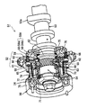
- FIG. 3 is a perspective view showing the internal structure of the phase variable device in FIG.
- FIG. 3 is used in a form assembled and integrated with an internal combustion engine 11 for an automobile, and the crank valve 22 is opened and closed in synchronization with the rotation of the crankshaft 22.
- the rotation of the shaft 22 is transmitted to the camshaft 53, and the device is configured to change the opening / closing timing of the intake / exhaust valves 15 and 17 of the internal combustion engine according to the operating state such as the load and the rotational speed of the internal combustion engine 11. .
- the phase varying device 51 includes an annular outer cylindrical portion 52 that is a sprocket to which the driving force of the crankshaft 22 of the internal combustion engine 11 is transmitted, and is disposed coaxially with the outer cylindrical portion 52 and is rotated relative to the outer cylindrical portion 52.
- the outer cylindrical portion 52 and the inner cylindrical portion are engaged by helical spline engagement with an annular inner cylindrical portion 54 on the driven side that constitutes a part of the camshaft 53, and the outer cylindrical portion 52 and the inner cylindrical portion 54, respectively.
- Electromagnetic brake means 56 provided on the arrangement side, and the electromagnetic brake means 56 is attached to a cover (engine case) 57.
- the intermediate moving member 55 and the electromagnetic brake means 56 constitute a phase variable mechanism.
- the outer cylinder part 52 is a driving rotator
- the inner cylinder part 54 is a driven rotator.
- the phase variable mechanism is driven by the electromagnetic brake means 56.
- the electromagnetic brake means 56 includes a system driven by an electric motor, and the phase variable mechanism may be hydraulically driven.
- the outer cylindrical portion 52 includes a sprocket main body 59 having a ring-shaped concave portion 58 provided on the inner peripheral edge, and an inner flange that is in close contact with the side surface of the sprocket main body 59 and cooperates with the concave portion 58 to define a flange engaging groove 58A.
- the plate 60 and the inner flange plate 60 are fastened and fixed together to the sprocket body 59, and a spline case 61 is formed with a spline engaging portion with the intermediate moving member 55 formed on the inner periphery.
- a stepped portion 58c is provided to face the outer peripheral edge of the flange 62 on the inner cylinder portion 54 side described later. Yes.
- the rotation of the crankshaft 22 of the internal combustion engine 11 is transmitted via the chain C to the outer cylinder 52 (sprocket body 59) which is a sprocket.
- Reference numeral 63 denotes a fastening screw that fixes and integrates the sprocket body 59, the inner flange plate 60, and the spline case 61.
- the sprocket body 59, the inner flange plate 60, and the spline case 61 constitute a sprocket (outer cylinder portion 52).
- the flange engaging groove 58A can be easily formed, and the spline engaging portion 64 in the outer tube portion 52 (spline case 61) can be easily formed.
- male and female helical splines 65 and 66 are provided on a part of the inner and outer peripheral surfaces of the intermediate moving member 55, and male helical splines 67 are provided on the outer peripheral surface of the inner cylindrical portion 54.
- a female helical spline 68 is provided on the inner peripheral surface of the spline case 61. Since the inner and outer splines 65 and 66 of the intermediate moving member 55 are formed as reverse helical splines, the inner cylindrical portion 54 is moved relative to the outer cylindrical portion 52 with a slight movement in the axial direction of the intermediate moving member 55. The phase can be changed greatly.
- a male screw part 69 is formed on the outer peripheral surface of the intermediate moving member 55.
- the electromagnetic brake means 56 is rotatably supported on the inner cylinder portion 54 by an electromagnetic clutch 70 supported by a cover (engine case) 57 and a bearing 71, and the male screw portion 69 of the intermediate moving member 55 is screwed together.
- the rotating drum 72 to which the braking force of the electromagnetic clutch 70 is transmitted, and the torsion coil spring 73 interposed between the rotating drum 72 and the outer cylindrical portion 52 in the axial direction are configured.
- the electromagnetic clutch 70 is mounted on the outer peripheral side of the boss portion 57a of the cover 57.
- a female square screw portion 74 is provided on the inner peripheral surface of the rotary drum 72, and the rotary drum 72 and the intermediate moving member 55 can be relatively rotated along the square screw portions 74 and 69 in the circumferential direction. That is, the intermediate moving member 55 can move in the axial direction while rotating along the square screw portions 74 and 69.
- the rotating drum 72 and the outer cylinder portion 52 are connected by a wound torsion coil spring 73.
- a wound torsion coil spring 73 When no braking force is applied to the rotating drum 72, the outer cylinder portion 52, the inner cylinder portion 54, and the intermediate movement The member 55 and the rotating drum 72 rotate together.
- the torsion coil spring 73 interposed between the rotating drum 72 and the outer cylindrical portion 52 (spline case 61) is interposed in the axial direction, the entire phase varying device extends in the axial direction, but the radial direction. It is compact.
- the intermediate moving member 55 moves in the axial direction while rotating along the square screw portions 74, 69.
- the phase of the cylinder part 52 and the inner cylinder part 54 changes, and the opening / closing timing of the valve by the cam 53a of the camshaft 53 is adjusted.
- the electromagnetic clutch 70 Before the electromagnetic clutch 70 is turned on (when no power is supplied), the electromagnetic clutch 70 is in the position indicated by the two-dot chain line in FIG. 2, and a gap is formed between the rotating drum 72 and the electromagnetic clutch 70.
- the outer cylinder part 52 and the inner cylinder part 54 rotate integrally without a phase difference.
- the electromagnetic clutch 70 When the electromagnetic clutch 70 is turned on (energized), the electromagnetic clutch 70 slides to the right in FIG. 2 to attract the rotary drum 72, whereby the braking force transmitted from the electromagnetic clutch 70 acts on the rotary drum 72. .
- a rotation delay with respect to the outer cylinder portion 52 occurs in the rotating drum 72 to which the braking force acts, that is, the intermediate moving member 55 moves forward (moves in the right direction in FIG. 2) by the square screw portions 69 and 74, and the intermediate moving member 55
- the male and female helical splines 65 and 66 cause the inner cylindrical portion 54 (camshaft 53) to rotate relative to the outer cylindrical portion 52 (sprocket main body 59) to change its phase.
- the rotating drum 72 is held at a position where the transmitted braking force and the spring force of the torsion coil spring 73 are balanced (position where the inner cylinder portion 54 has a predetermined phase difference with respect to the outer cylinder portion 52).
- a flange 62 is provided around the outer peripheral surface of the inner cylinder portion 54 (journal surface with the sprocket main body 59), while the flange 62 is engaged with the inner peripheral surface of the outer cylinder portion 52 (sprocket main body 59).
- a flange engaging groove 58A is provided around the friction engaging member 75 and 76 between the side surface of the flange 62 and the side surface of the flange engaging groove 58A.
- FIG. 4 shows a control system design model of the phase variable device 51 which is a control target of the control method according to the embodiment of the present invention.
- the clutch torque of the electromagnetic clutch 70 acts so as to oppose the spring torque direction of the torsion coil spring 73 to which the initial torque is applied, and the relative angle of the inner cylinder part 54 with respect to the outer cylinder part 52 is the phase. It shows what happens in the conversion direction.
- Equation 1 The equation of state of this design model is shown in Equation 1.
- X (t) is a state variable representing the internal state of the phase variable device 51 to be controlled
- d (t) is an input variable to the phase variable device 51
- y (t) is an output variable of the phase variable device
- A, B , C, and D indicate coefficients that can be obtained from the components of the phase varying device 51.
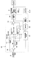
- FIG. 5 shows a block diagram of a control configuration of the control device according to the embodiment of the present invention.
- the phase control apparatus includes a speed difference calculator 105 that receives positional information from the sliding mode controller 103, the crank angle sensor 23, and the cam angle sensor 24, and calculates a rotational speed difference of the cam, and the speed difference calculator 105.
- An integrator 106 that integrates the velocity value from the phase
- a phase variable device estimator 107 that calculates a relative angle estimated value from the output of the integrator 106, and an output value that is used to obtain a target relative angle that has been registered in advance.
- the feed forward controller 111 is configured by a subtractor 108, a differentiator 109, an adder 110, and a PWM (pulse width modulation) drive circuit 104 that receives an output signal from the adder 110 and controls the electromagnetic clutch 70.
- the electromagnetic clutch 70 of the phase variable device 51 is controlled by the current from the PWM drive circuit.
- the system By calculating the command value for the electromagnetic clutch 70 from the output value from the sliding mode controller 103 and the output value from the feedforward controller 111 that outputs the target relative angle registered in advance, the system The whole can be made more resistant to disturbance.
- Equation 3 A state equation of a target trajectory having a relative angle for performing the feedforward control is shown in Formula 2.
- r (t) is a target conversion angle
- Xr (t) is an internal state of the feedforward control system
- Ar is a feedforward control system matrix
- Br is a feedforward control input matrix.
- the input target value at this time is a step input. From Equations 1 and 2, the state equation Equation 3 can be obtained.
- Equation 4 When d (t) is divided into d 1 (t) by feedback and feedforward input d 2 (t), Equation 4 is obtained, and the feedforward input is given by Equation 5. At this time, E is the deviation between the target conversion angle and the current conversion angle.
- the design of the sliding mode controller 103 includes a design of a switching hyperplane (equivalent control input) as a first stage, a design of a reaching law (nonlinear switching input) and a design for chattering prevention as a second stage.
- the design of the switching hyperplane that constrains the state, which is the first stage is basically a design of a linear control system, so that the design is performed by a method based on an optimal control theory that is a linear control theory.
- Expression 6 is obtained by using an expansion system obtained by adding an integrator to Expression 4, and the evaluation function in Expression 8 is used.
- Q represents a sliding mode weight function.
- Equation 10 Solution to the evaluation function J of Equation 8 to minimize is represented using positive definite symmetric only solution P E Riccati equation of Equation 9, the switching hyperplane may be expressed by Equation 10.
- Equation 11 When in the sliding mode, the condition of Equation 11 is applied, and the equivalent control input d req is obtained from Equation 12 as in Equation 13.
- ⁇ is a sliding mode switching function.
- the nonlinear switching input is defined by Equation 14 according to the final sliding mode control method. If a smoothing function is used to prevent chattering and further an acceleration rate reaching law function is used, a nonlinear switching input is obtained as shown in Equation 15. At this time, ⁇ is a sliding mode relay input gain.
- the sliding mode controller 103 can be expressed as Equation 16 and, when the Ford Forward controller according to the embodiment of the present invention is used, it can be expressed as Equation 17.
- the Kalman filter constituting the phase variable device estimator 107 will be described with reference to FIG.
- Formula 1 is discretized with the control period
- Formula 18 is obtained.
- "D" attached to the lower right of each character represents discretization.
- the phase variable device estimator 107 outputs one estimated relative angle value by a plurality of inputs.
- the speed difference calculator 105 calculates the rotation speed value calculated by the crank angle sensor 23 that detects the rotation of the crankshaft 22 and the rotation speed value calculated by the cam angle sensor 24 that detects the rotation of the intake camshaft 20.
- a speed difference between the shafts is calculated, and an integrator 106 calculates a relative angle between the shafts at the current step (hereinafter referred to as “relative angle at the current step”), which is input to the phase variable device estimator 107. .
- the command value of the current step to the electromagnetic clutch 70 is also input to the phase variable device estimator 107.
- a relative angle estimation value after one step is calculated from these inputs using a Kalman filter constituting the phase variable device estimator 107, and this is input as a feedback signal to the sliding mode controller 103.
- a relative angle estimated value after one step is calculated using a Kalman filter, By inputting this as a feedback signal to the sliding mode controller 103, a necessary number of input signals to the controller can be obtained even when the rotation speed of the crankshaft 22 is small. As a result, the control system can be made highly responsive and stable.
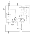
- the phase variable device estimator 107 will be described in detail with reference to the block diagram of FIG.
- the phase variable device estimator 107 in FIG. 6 is shown as an input on the right and an output on the left in accordance with FIG.
- the phase variable device estimator 107 according to the first embodiment of the present invention includes Kalman filters 121 (Equation 19 first equation, Equation 20 first equation), 115 (Equation 20 third equation), 117 represented by Equation 19 and Equation 20. (Equation 20 fifth equation), 118 (Equation 20 second equation), and a plurality of change-over switches 113, 115 and the like that switch the input by a sensor flag.
- the sensor flag is a cam angle sensor 24 that is a proximity sensor for calculating the number of rotations of the camshaft 53.
- the state in which the cam angle sensor is on is the state in which the sensor flag is on, and is off. The state where the sensor flag is not set.
- ON and OFF may be reversed, and the sensor may be a crankshaft 22 sensor instead of a camshaft 53 sensor.
- the change-over switches 113 and 116 both select 0 value of 119.
- the output from the first changeover switch 113 is always 0, and the Kalman filter 120 of the first equation of Equation 19 calculates the relative angle estimated value after one step from only the command value at the current step to the electromagnetic clutch 70. .
- This state is assumed to be open loop estimation.
- both the selector switches 113 and 116 select a value other than 0 value 119.
- the estimated relative angle value is calculated by the Kalman filters 115, 117, 118, and 120 using the relative angle at the current step and the command value at the current step for the electromagnetic clutch 70. This state is referred to as closed loop estimation.
- This Kalman filter is an Unscented Kalman filter used in a nonlinear system.
- the Kalman filter calculates the estimated relative angle value after one step from only the command value at the current step for the electromagnetic clutch 70, and the sensor flag is set.
- the Kalman filter calculates the estimated relative angle value after one step using the relative angle at the current step and the command value at the current step of the electromagnetic clutch 70. A highly accurate value can be taken in and calculated, and a highly accurate command can be given to the electromagnetic clutch.
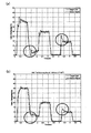
- FIG. 7 shows the result of controlling the internal combustion engine 11 by the phase control method according to the first embodiment of the present invention.
- FIG. 7A shows the case where the phase variable device estimator 107 is not used
- FIG. 7B shows the state estimated by the phase variable device estimator 107 according to the first embodiment.
- the X axis represents time
- the Y axis represents the phase, that is, the relative angle between the outer cylindrical portion 52 and the inner cylindrical portion 54 in the phase varying device 51.
- the number of revolutions of the internal combustion engine 11 is 1000 [rpm]
- a graph indicated by a one-dot chain line is a phase command value
- a solid line is an actual phase measurement value.
- overshoot and undershoot could be suppressed in the portion immediately after changing the phase (the portion surrounded by ⁇ ), and good responsiveness could be obtained.
- the phase variable device estimator 107 performs system identification of the phase variable device 51 and calculates a relative angle estimated value. Specifically, system identification of the phase variable device 51 is performed using the Kalman filter in the phase variable device estimator 107 from the relative angle at the current step and the command value of the current step to the electromagnetic clutch 70. With this system identification, it is possible to create a parametric model in which the state of each element in the phase varying device 51 is specified. For example, it can be specified as a model including a spring constant or viscosity when the temperature environment in the phase varying device 51 changes. Then, the estimated relative angle after one step is calculated by the parametric model obtained by this system identification.
- the accuracy of the control model can be improved by performing system identification of the phase variable device 51 using a Kalman filter and calculating a relative angle estimated value after one step using the parametric model obtained by this system identification. Thereby, a highly accurate command can be performed by the electromagnetic clutch 70.
- a control method and a control apparatus using a phase variable device estimator 107 such as a Kalman filter have been proposed for a system using the sliding mode controller 103.
- a PID controller other than the sliding mode controller 107 is used.
- a control method or control device using a general feedback controller is also possible.
Landscapes
- Engineering & Computer Science (AREA)
- Mechanical Engineering (AREA)
- General Engineering & Computer Science (AREA)
- Combustion & Propulsion (AREA)
- Chemical & Material Sciences (AREA)
- General Physics & Mathematics (AREA)
- Automation & Control Theory (AREA)
- Physics & Mathematics (AREA)
- Health & Medical Sciences (AREA)
- Artificial Intelligence (AREA)
- Computer Vision & Pattern Recognition (AREA)
- Evolutionary Computation (AREA)
- Medical Informatics (AREA)
- Software Systems (AREA)
- Manufacturing & Machinery (AREA)
- Human Computer Interaction (AREA)
- Output Control And Ontrol Of Special Type Engine (AREA)
- Valve Device For Special Equipments (AREA)
Abstract
Priority Applications (5)
| Application Number | Priority Date | Filing Date | Title |
|---|---|---|---|
| US14/749,901 US9416689B2 (en) | 2012-12-28 | 2012-12-28 | Method and apparatus for controlling a phase varying apparatus |
| PCT/JP2012/084127 WO2014103030A1 (fr) | 2012-12-28 | 2012-12-28 | Procédé et dispositif pour commander un dispositif à phase variable |
| JP2014554019A JP5967456B2 (ja) | 2012-12-28 | 2012-12-28 | 位相可変装置の制御方法及び制御装置 |
| KR1020157019269A KR20150099789A (ko) | 2012-12-28 | 2012-12-28 | 위상 가변 장치의 제어 방법 및 제어 장치 |
| DE112012007268.5T DE112012007268T5 (de) | 2012-12-28 | 2012-12-28 | Ein Verfahren und eine Vorrichtung zum Steuern einer Phasenänderungsvorrichtung |
Applications Claiming Priority (1)
| Application Number | Priority Date | Filing Date | Title |
|---|---|---|---|
| PCT/JP2012/084127 WO2014103030A1 (fr) | 2012-12-28 | 2012-12-28 | Procédé et dispositif pour commander un dispositif à phase variable |
Publications (1)
| Publication Number | Publication Date |
|---|---|
| WO2014103030A1 true WO2014103030A1 (fr) | 2014-07-03 |
Family
ID=51020180
Family Applications (1)
| Application Number | Title | Priority Date | Filing Date |
|---|---|---|---|
| PCT/JP2012/084127 Ceased WO2014103030A1 (fr) | 2012-12-28 | 2012-12-28 | Procédé et dispositif pour commander un dispositif à phase variable |
Country Status (5)
| Country | Link |
|---|---|
| US (1) | US9416689B2 (fr) |
| JP (1) | JP5967456B2 (fr) |
| KR (1) | KR20150099789A (fr) |
| DE (1) | DE112012007268T5 (fr) |
| WO (1) | WO2014103030A1 (fr) |
Cited By (2)
| Publication number | Priority date | Publication date | Assignee | Title |
|---|---|---|---|---|
| CN104950899A (zh) * | 2015-06-10 | 2015-09-30 | 北京理工大学 | 一种固定时间收敛的飞行器姿态控制方法 |
| US9416689B2 (en) | 2012-12-28 | 2016-08-16 | Nittan Valve Co., Ltd. | Method and apparatus for controlling a phase varying apparatus |
Families Citing this family (1)
| Publication number | Priority date | Publication date | Assignee | Title |
|---|---|---|---|---|
| CN108362493B (zh) * | 2018-01-23 | 2019-10-11 | 大连理工大学 | 一种数控机床直线轴转角误差快速检测方法 |
Citations (8)
| Publication number | Priority date | Publication date | Assignee | Title |
|---|---|---|---|---|
| JPS63128401A (ja) * | 1986-11-18 | 1988-06-01 | Hitachi Ltd | 比例・積分形予測適応制御装置 |
| JP2001336504A (ja) * | 2000-05-25 | 2001-12-07 | Sumitomo Heavy Ind Ltd | 気体圧アクチュエータの制御方法及び制御装置 |
| JP2002161767A (ja) * | 2000-11-30 | 2002-06-07 | Unisia Jecs Corp | 電磁式可変バルブタイミング装置の制御装置 |
| JP2002180854A (ja) * | 2000-12-08 | 2002-06-26 | Unisia Jecs Corp | 電磁式可変バルブタイミング装置の制御装置 |
| JP2003206710A (ja) * | 2002-01-16 | 2003-07-25 | Hitachi Unisia Automotive Ltd | 可変バルブタイミング機構の制御装置 |
| JP2007531478A (ja) * | 2003-07-10 | 2007-11-01 | ハネウェル・インターナショナル・インコーポレーテッド | 電動機駆動システム用のセンサレス制御方法および装置 |
| JP2007537896A (ja) * | 2004-05-18 | 2007-12-27 | ハスキー インジェクション モールディング システムズ リミテッド | 射出成形システムのエネルギー管理装置及び方法 |
| JP2009131406A (ja) * | 2007-11-29 | 2009-06-18 | Olympus Medical Systems Corp | 内視鏡システム |
Family Cites Families (10)
| Publication number | Priority date | Publication date | Assignee | Title |
|---|---|---|---|---|
| JPH0421046Y2 (fr) | 1987-02-13 | 1992-05-14 | ||
| JP2740828B2 (ja) | 1988-12-29 | 1998-04-15 | 広栄化学工業株式会社 | N,n―ジイソプロピルエチルアミンの製造法 |
| JPH02161767A (ja) | 1989-07-21 | 1990-06-21 | Fujitsu Ltd | 半導体装置の製造方法 |
| JPH03206710A (ja) | 1990-01-08 | 1991-09-10 | Fuji Electric Co Ltd | 光駆動半導体装置 |
| JPH08115867A (ja) | 1994-10-18 | 1996-05-07 | Hitachi Ltd | レジスト塗布装置 |
| JPH09131406A (ja) | 1995-11-09 | 1997-05-20 | Sanyo Electric Co Ltd | 導 子 |
| JP2001036504A (ja) | 1999-07-19 | 2001-02-09 | Nippon Telegr & Teleph Corp <Ntt> | 光波長多重ネットワークにおけるクロック分配方法及びクロック分配システム |
| JP2001132482A (ja) * | 1999-11-01 | 2001-05-15 | Unisia Jecs Corp | 内燃機関のバルブタイミング制御装置 |
| JP5752960B2 (ja) * | 2011-03-10 | 2015-07-22 | ダイヤモンド電機株式会社 | 電磁式可変バルブタイミング装置用の制御装置 |
| WO2014103030A1 (fr) | 2012-12-28 | 2014-07-03 | 日鍛バルブ株式会社 | Procédé et dispositif pour commander un dispositif à phase variable |
-
2012
- 2012-12-28 WO PCT/JP2012/084127 patent/WO2014103030A1/fr not_active Ceased
- 2012-12-28 DE DE112012007268.5T patent/DE112012007268T5/de not_active Withdrawn
- 2012-12-28 KR KR1020157019269A patent/KR20150099789A/ko not_active Withdrawn
- 2012-12-28 US US14/749,901 patent/US9416689B2/en not_active Expired - Fee Related
- 2012-12-28 JP JP2014554019A patent/JP5967456B2/ja not_active Expired - Fee Related
Patent Citations (8)
| Publication number | Priority date | Publication date | Assignee | Title |
|---|---|---|---|---|
| JPS63128401A (ja) * | 1986-11-18 | 1988-06-01 | Hitachi Ltd | 比例・積分形予測適応制御装置 |
| JP2001336504A (ja) * | 2000-05-25 | 2001-12-07 | Sumitomo Heavy Ind Ltd | 気体圧アクチュエータの制御方法及び制御装置 |
| JP2002161767A (ja) * | 2000-11-30 | 2002-06-07 | Unisia Jecs Corp | 電磁式可変バルブタイミング装置の制御装置 |
| JP2002180854A (ja) * | 2000-12-08 | 2002-06-26 | Unisia Jecs Corp | 電磁式可変バルブタイミング装置の制御装置 |
| JP2003206710A (ja) * | 2002-01-16 | 2003-07-25 | Hitachi Unisia Automotive Ltd | 可変バルブタイミング機構の制御装置 |
| JP2007531478A (ja) * | 2003-07-10 | 2007-11-01 | ハネウェル・インターナショナル・インコーポレーテッド | 電動機駆動システム用のセンサレス制御方法および装置 |
| JP2007537896A (ja) * | 2004-05-18 | 2007-12-27 | ハスキー インジェクション モールディング システムズ リミテッド | 射出成形システムのエネルギー管理装置及び方法 |
| JP2009131406A (ja) * | 2007-11-29 | 2009-06-18 | Olympus Medical Systems Corp | 内視鏡システム |
Cited By (2)
| Publication number | Priority date | Publication date | Assignee | Title |
|---|---|---|---|---|
| US9416689B2 (en) | 2012-12-28 | 2016-08-16 | Nittan Valve Co., Ltd. | Method and apparatus for controlling a phase varying apparatus |
| CN104950899A (zh) * | 2015-06-10 | 2015-09-30 | 北京理工大学 | 一种固定时间收敛的飞行器姿态控制方法 |
Also Published As
| Publication number | Publication date |
|---|---|
| JPWO2014103030A1 (ja) | 2017-01-12 |
| KR20150099789A (ko) | 2015-09-01 |
| US9416689B2 (en) | 2016-08-16 |
| US20150377084A1 (en) | 2015-12-31 |
| JP5967456B2 (ja) | 2016-08-10 |
| DE112012007268T5 (de) | 2015-10-08 |
Similar Documents
| Publication | Publication Date | Title |
|---|---|---|
| JP3733600B2 (ja) | エンジンの弁動作タイミング調整装置 | |
| US8091523B2 (en) | Apparatus for and method of controlling variable valve timing mechanism | |
| CN101008354A (zh) | 用于控制运动机构的装置和方法 | |
| JP5967456B2 (ja) | 位相可変装置の制御方法及び制御装置 | |
| JP2003206710A (ja) | 可変バルブタイミング機構の制御装置 | |
| JP7157634B2 (ja) | 可変バルブタイミング機構の制御装置及びその制御方法 | |
| JP3395240B2 (ja) | 内燃機関用バルブタイミング制御装置 | |
| JP3961237B2 (ja) | 可変バルブタイミング装置の制御装置 | |
| JP4115663B2 (ja) | 可変バルブタイミング装置の診断装置 | |
| JP3859920B2 (ja) | エンジンの可変バルブタイミング装置 | |
| CN103670728B (zh) | 可变气门机构的控制装置及控制方法 | |
| JP2013155630A (ja) | 電動式可変バルブタイミング装置の制御装置 | |
| JP2009174473A (ja) | 可変バルブタイミング機構の制御装置 | |
| JP4956454B2 (ja) | 可変バルブタイミング機構の制御装置 | |
| JP5720855B2 (ja) | 内燃機関の制御装置 | |
| JP3874986B2 (ja) | エンジンの可変バルブタイミング装置 | |
| JP4659591B2 (ja) | 車両用エンジンの吸気制御装置 | |
| JP4940934B2 (ja) | 可変動弁機構の制御装置 | |
| JP5033612B2 (ja) | 可変動弁機構、可変動弁機構の制御装置及びこれを備えた内燃機関 | |
| JP5303383B2 (ja) | カム位相可変型内燃機関 | |
| JP2010077821A (ja) | 電子ガバナの制御方法及びその制御装置 | |
| JP3299473B2 (ja) | 内燃機関のバルブタイミング制御装置 | |
| JP2005226534A (ja) | 動弁制御装置 | |
| JPH07332118A (ja) | エンジンのバルブタイミング調整装置 | |
| JP2003328786A (ja) | 可変バルブタイミング機構の制御装置 |
Legal Events
| Date | Code | Title | Description |
|---|---|---|---|
| 121 | Ep: the epo has been informed by wipo that ep was designated in this application |
Ref document number: 12890675 Country of ref document: EP Kind code of ref document: A1 |
|
| DPE1 | Request for preliminary examination filed after expiration of 19th month from priority date (pct application filed from 20040101) | ||
| ENP | Entry into the national phase |
Ref document number: 2014554019 Country of ref document: JP Kind code of ref document: A |
|
| WWE | Wipo information: entry into national phase |
Ref document number: 14749901 Country of ref document: US |
|
| WWE | Wipo information: entry into national phase |
Ref document number: 112012007268 Country of ref document: DE Ref document number: 1120120072685 Country of ref document: DE |
|
| ENP | Entry into the national phase |
Ref document number: 20157019269 Country of ref document: KR Kind code of ref document: A |
|
| 122 | Ep: pct application non-entry in european phase |
Ref document number: 12890675 Country of ref document: EP Kind code of ref document: A1 |