WO2014103065A1 - Dispositif de traitement d'images médicales et procédé de traitement d'images - Google Patents
Dispositif de traitement d'images médicales et procédé de traitement d'images Download PDFInfo
- Publication number
- WO2014103065A1 WO2014103065A1 PCT/JP2012/084214 JP2012084214W WO2014103065A1 WO 2014103065 A1 WO2014103065 A1 WO 2014103065A1 JP 2012084214 W JP2012084214 W JP 2012084214W WO 2014103065 A1 WO2014103065 A1 WO 2014103065A1
- Authority
- WO
- WIPO (PCT)
- Prior art keywords
- image
- rendering
- unit
- volume data
- depth information
- Prior art date
- Legal status (The legal status is an assumption and is not a legal conclusion. Google has not performed a legal analysis and makes no representation as to the accuracy of the status listed.)
- Ceased
Links
Images



Classifications
-
- G—PHYSICS
- G06—COMPUTING OR CALCULATING; COUNTING
- G06T—IMAGE DATA PROCESSING OR GENERATION, IN GENERAL
- G06T15/00—Three-dimensional [3D] image rendering
- G06T15/08—Volume rendering
-
- G—PHYSICS
- G06—COMPUTING OR CALCULATING; COUNTING
- G06T—IMAGE DATA PROCESSING OR GENERATION, IN GENERAL
- G06T15/00—Three-dimensional [3D] image rendering
- G06T15/50—Lighting effects
- G06T15/506—Illumination models
-
- G—PHYSICS
- G06—COMPUTING OR CALCULATING; COUNTING
- G06T—IMAGE DATA PROCESSING OR GENERATION, IN GENERAL
- G06T19/00—Manipulating three-dimensional [3D] models or images for computer graphics
- G06T19/006—Mixed reality
-
- G—PHYSICS
- G06—COMPUTING OR CALCULATING; COUNTING
- G06T—IMAGE DATA PROCESSING OR GENERATION, IN GENERAL
- G06T19/00—Manipulating three-dimensional [3D] models or images for computer graphics
- G06T19/20—Editing of three-dimensional [3D] images, e.g. changing shapes or colours, aligning objects or positioning parts
Definitions
- the present invention relates to a medical image processing apparatus and an image processing method for processing volume data and displaying an image of a tissue or the like in a human body.
- Non-Patent Document 1 There is Volume Shade Imaging (Non-Patent Document 1) as background technology in this technical field.
- This Non-Patent Document 1 shows that volume data, depth information, and edge information can be combined to generate a more realistic and highly visible volume rendering image.
- Non-Patent Document 2 describes a technique for realistically rendering human skin and face.
- this method when a face is rendered, it is divided into three layers, each of which is a dermis, epidermis, and oil.
- the dermis and epidermis there is a method called Sub-Surface Scattering as a rendering method that reproduces the high texture in computer graphics. Rendering is performed using this method.
- Subsurface scattering is a technique used to create computer graphics for humans, and is a technology that reproduces the physical phenomenon in which light penetrates and diffuses over the skin surface for a short distance.
- the oil is mainly the part that reproduces the light of the face.
- Non-Patent Document 3 describes a technique for volume rendering a material having subsurface diffusion. This method is a method of creating a light volume that represents the degree of light hit from the direction of the light source.
- volume rendering is performed for intuitive visualization.
- An ultrasonic diagnostic apparatus that employs volume rendering is used for medical purposes, and even if the object to be diagnosed is a human body, the appearance may be an inorganic image and may differ from the actual object.
- a calculation model for expressing actual optical characteristics is generally used, but there is a problem that the amount of calculation increases.
- ultrasonic waves are less straight ahead than light, and diffraction and other wraparounds occur more strongly. Therefore, ultrasonic images generally generate more noise components such as speckles than optical photographs. . Therefore, in order to obtain a beautiful image, preprocessing such as noise and obstacle removal and smoothing is necessary.
- preprocessing such as noise and obstacle removal and smoothing is necessary.
- volume data is at least three-dimensional data, it is necessary to perform preprocessing on the whole. There is a problem with high costs.
- the process of generating the rendered image by processing the volume data is intuitively and intuitively understood by humans from the volume data called rendering, the part that removes noise from the original data called preprocessing, and the part extraction. It is divided into a portion to be visualized as a two-dimensional image and a portion for adjusting the color and contrast of the two-dimensional image called post-processing. In this case, for example, if the amount of preprocessing increases, the total amount of calculation increases, and a high-quality volume rendering image cannot be generated without increasing the calculation cost.
- An object of the present invention is to provide a medical image processing apparatus and an image processing method capable of generating a high-quality rendered image without increasing the calculation cost.
- the present invention converts a three-dimensional volume data input from a modality into two-dimensional volume data, and generates a two-dimensional rendering image; Based on the depth information generated by the depth information generation unit that generates depth information indicating the length from the virtual viewpoint position in the virtual three-dimensional space to the three-dimensional volume data based on the volume data, An image including an anti-aliasing unit that specifies a target in a rendering image generated by the volume rendering unit and executes anti-aliasing processing on an edge portion of the specified target, and an image including the target subjected to the anti-aliasing processing Display as a rendered image And having a, the.
- a high-quality rendered image can be generated without increasing the calculation cost.
- FIG. 1 is a configuration diagram of a medical image processing apparatus.
- the medical image processing apparatus 10 includes an input / output interface 12, a volume rendering unit 14, and a display 16, and the input / output interface 12 is connected to the display 16 via the volume rendering unit 14.
- the volume rendering unit 14 includes a memory 18, a CPU (Central Processing Unit) 20, a GPU (Graphics Processing Unit) 22, and a storage device 24, and each unit is connected to each other via a bus 26.
- CPU Central Processing Unit
- GPU Graphics Processing Unit
- the input / output interface 12 is an interface for inputting three-dimensional volume data from the modality, and functions as a volume data input unit for inputting volume data, for example.
- a detector for an ultrasonic diagnostic apparatus can be used as a modality. For example, this detector scans an ultrasonic wave from the ultrasonic probe to the tomographic plane (scanning plane) inside the measurement object, and receives a reflected echo signal returning from each part of the biological tissue on the tomographic plane.
- the input / output interface 12 may include a probe connected to the ultrasonic probe.
- the memory 18 constitutes a storage unit for storing various programs and data.
- the CPU 20 is a processor that performs overall control of the entire volume rendering unit 14, and executes various processes according to programs stored in the memory 18. Note that an input device such as a mouse or a keyboard is connected to the CPU 20.
- the GPU 22 executes data processing relating to the three-dimensional volume data input from the input / output interface 12, for example, volume rendering processing, etc., generates image data from the three-dimensional volume data, and follows the generated image data A process for displaying the displayed image, for example, a volume rendering image on the display 16 is executed.
- the storage device 24 is configured as a storage unit that stores three-dimensional volume data and the like.
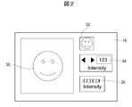
- FIG. 2 is a configuration diagram of the display.
- the display 16 is composed of, for example, a liquid crystal display, a touch panel display, or a three-dimensional display.
- a rendering image 30 obtained by volume rendering processing of the GPU 22 is displayed, and a button 32, a numerical value input box 34, and a slider bar 36 are displayed.
- the button 32 is a button on the touch panel or an on / off physical button. For example, by operating the button 32, operation information indicating the presence or absence of anti-aliasing is input to the GPU 22.
- the numerical value input box 34 is a box used when inputting numerical values for the strength of anti-aliasing from a keyboard or the like. For example, when a numerical value indicating the strength of anti-aliasing is input to the numerical value input box 34 from the keyboard, information indicating the strength of anti-aliasing is input to the GPU 22.
- the slider bar 36 is a bar that moves to the left and right in response to an operation from the keyboard or a touch panel, and adjusts the strength of anti-aliasing and the color density of volume rendering. Information corresponding to the position of the slider bar 36 is input to the GPU 22 as information for adjusting the strength of anti-aliasing and the color density of volume rendering.
- the button 32 and the numerical value input box 34 can also be used as a button or a box for adjusting the color density of volume rendering.
- the position of the button 32 on the display 16 is not limited, and the button 32 may be arranged anywhere on the display 16. Further, it is not necessary to display all information on the display 16 collectively, and the display 16 can be divided into two.
- the display 16 is composed of two upper and lower displays, the upper display is a liquid crystal display, the rendered image 30 is displayed on the upper display, the lower display is a touch panel display, the lower display is a button 32 or a numeric input box 34. Etc. can also be displayed.
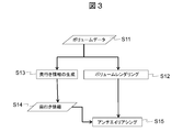
- FIG. 3 is a flowchart for explaining processing for adding an anti-aliasing effect to a rendering image using depth information. This process is executed by the GPU 22.
- the GPU 22 inputs three-dimensional volume data from the input interface 12 (S11).
- the three-dimensional volume data is usually a three-dimensional array, and the elements of each array are integer values represented by 8 bits.
- As the three-dimensional volume data a small number of floating-point data of about 16 bits can be used.
- the GPU 22 executes a volume rendering process for generating a two-dimensional rendering image based on the three-dimensional volume data (S12), and generates depth information based on the three-dimensional volume data.
- the process is executed (S13).
- the rendered image is an element of a two-dimensional array, and each array element is an 8-bit integer value.
- Each array element includes an integer vector value indicating each of red, blue, and green components representing the three primary colors of light.
- a floating-point vector value can be used instead of the integer vector value.
- the GPU 22 When the GPU 22 generates depth information based on three-dimensional volume data, the GPU 22 performs ray casting to obtain the depth value of the volume data. Ray casting extends the line segment connecting the virtual viewpoint position set in the virtual three-dimensional space and the position of the corresponding two-dimensional array on the rendered image plane, and integrates the position where the extended line segment and the volume data intersect. It is processing. This process is performed with the volume resolution as the final resolution.
- the GPU 22 holds the depth information obtained by the process of step S13 (S14).
- the depth information is an element of a two-dimensional array as in the rendering image, and the element of each array is usually an integer value of about 8 bits. A floating decimal point can be used instead of the integer value.
- the polygon information is created from the volume data by using the depth coordinate of the near position where the ray collides or the marching cube.
- a method for obtaining a depth value from a polygon is a common technique in the surface rendering technology. For example, if the Z buffer method is used for surface rendering rendering, the value of the Z buffer can be used as the depth value.
- the GPU 22 identifies a target in the rendered image obtained in step S12 based on the depth information held in step S14, and performs anti-aliasing for blurring the edge portion in the identified target.
- the processing is executed, a rendering image 30 is generated as a high-resolution final image, the generated rendering image 30 is displayed on the display 16 (S15), and the processing in this routine is terminated.
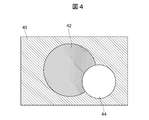
- FIG. 4 is a conceptual diagram of an image specified by depth information.
- the image specified by the depth information when the image specified by the depth information is a grayscale image, the image specified by the depth information at the position farthest from the virtual viewpoint position in the virtual three-dimensional space (the back side) is a black image. 40.
- the image specified by the depth information of the intermediate position from the virtual viewpoint position in the virtual three-dimensional space is a gray image 42, and is specified by the depth information of the position (front side) closest to the virtual viewpoint position in the virtual three-dimensional space.
- the image to be processed becomes a white image 44.
- the GPU 22 functions as a data processing unit that processes three-dimensional volume data, and converts the three-dimensional volume data into two-dimensional volume data to generate a two-dimensional rendering image.
- a depth information generation unit that generates depth information indicating the length from the virtual viewpoint position in the virtual three-dimensional space to the three-dimensional volume data based on the three-dimensional volume data input to the volume data input unit
- an anti-aliasing unit that identifies a target in a rendering image generated by the volume rendering unit based on depth information generated by the depth information generation unit, and executes anti-aliasing processing on the edge portion of the specified target Function.
- the display 16 functions as a display unit that displays an image including the target subjected to the anti-aliasing process as a rendered image.
- a two-dimensional rendering image is generated based on three-dimensional volume data, and two-dimensional depth information is generated, and a target in the generated rendering image is determined based on the generated depth information. Since the anti-aliasing process is performed on the specified target and the edge portion in the specified target, the high-resolution rendering image 30 can be generated without increasing the amount of calculation. It is possible to generate a high-quality rendering image 30 without increasing the image quality.
- This embodiment removes obstacles and floating objects using depth information, and the configuration of the medical image processing apparatus 10 is the same as that of the first embodiment.
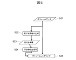
- FIG. 5 is a flowchart for explaining processing for removing obstacles / floating objects using depth information. This process is executed by the GPU 22.
- the GPU 22 inputs three-dimensional volume data from the input interface 12 (S21).
- the three-dimensional volume data the same data as in the first embodiment can be used.
- the GPU 22 executes a process for generating depth information based on the three-dimensional volume data (S22), and holds the depth information obtained by this process (S23). At this time, the depth information similar to that in the first embodiment can be used as the depth information.
- the GPU 22 executes a process of extracting floating objects and obstacles based on the held depth information (S24). At this time, the GPU 22 extracts the size and thickness of the suspended matter, and extracts an obstacle using the difference from the depth information at the adjacent position.
- the parameters for specifying the extraction target can be changed using the button 32 or the numerical value input box 34. Examples of parameters include, for example, differences in obstacle size, thickness, and depth information. As the size of the obstacle, for example, an area value can be used.
- the GPU 22 executes a volume rendering process for generating a two-dimensional rendering image based on the three-dimensional volume data, and generates a high-resolution final image (S25). Processing in this routine Exit. Note that after step S25, the target in the rendering image can be specified based on the depth information, and anti-aliasing processing for blurring the edge portion in the specified target can be executed.
- the GPU 22 generates a two-dimensional rendering image by ignoring the volume data corresponding to the suspended matter or obstacle extracted in the process of step S24 from the three-dimensional volume data. That is, the GPU 22 removes the volume data corresponding to the floating object and the obstacle from the input three-dimensional volume data, and the volume data remaining after the volume data corresponding to the floating object and the obstacle is removed. Is used to generate a rendering image to be a high-resolution final image, and the generated rendering image 30 is displayed on the display 16.
- the obstacle and noise removal that is normally performed in the pre-processing is performed in the post-processing, so that an increase in the amount of calculation can be suppressed.
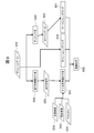
- FIG. 6 is a process explanatory diagram illustrating the process of volume data processing.
- pre-processing 62 is executed on the volume data 61, then rendering processing 63 is executed, post-processing 64 is executed after rendering processing 63, and finally rendering obtained by post-processing 64 is performed.
- the calculation amount of the pre-process 62 becomes a data size of the cube of N when the one-dimensional size of the volume data 61 is N.
- the calculation time is N 6.
- the calculation amount of the rendering process 63 is a data size of the square of M, where M is the one-dimensional size of the final two-dimensional image.
- the rendering process 63 has a calculation amount of N to the third power when N ⁇ M. Further, the post-processing 64 has a calculation amount of about M square ( ⁇ N square). Therefore, when the floating object or obstacle is extracted by post-processing, the calculation amount is greatly reduced.
- the GPU 22 functions as a volume rendering unit and a depth information generation unit, and also functions as a floating substance extraction unit that extracts volume data corresponding to the floating substance based on the depth information generated by the depth information generation unit.
- the volume rendering unit removes the volume data extracted by the suspended matter extraction unit from the input three-dimensional volume data, and performs a second process based on the volume data remaining after the volume data is removed. Generate a dimensional rendering image.
- two-dimensional depth information is generated based on the three-dimensional volume data, and floating objects and obstacles are extracted based on the generated depth information, and the extracted floating objects and obstacles are handled.
- Volume data is removed from 3D volume data, and 2D rendering images are generated based on the volume data from which the volume data corresponding to the extracted floating objects and obstacles have been removed.
- a high-resolution rendering image 30 can be generated without increasing.
- the effect of an oil layer is added using light source information and depth information, and the configuration of the medical image processing apparatus 10 is the same as that of the first embodiment.
- FIG. 7 is a flowchart for explaining processing for adding an oil layer effect using light source information and depth information. This process is executed by the GPU 22.
- the GPU 22 inputs three-dimensional volume data from the input interface 12 (S31).
- the three-dimensional volume data the same data as in the first embodiment can be used.
- the GPU 22 executes a process for generating depth information based on the three-dimensional volume data (S32), and holds the depth information obtained by this process (S33). At this time, the depth information similar to that in the first embodiment can be used as the depth information.
- the GPU 22 inputs the light source information (S34), inputs the texture information (S35), further inputs the texture (S36), and inputs the light source information, the texture information, the texture, and the held depth.
- An oil layer image is generated based on the information (S37).
- the light source information is information indicating the shape, intensity, brightness, position, and orientation of the light source.
- the texture information is information indicating how the light hits.
- the texture is information indicating the pattern and reflection characteristics of the object irradiated with light from the light source.
- the GPU 22 executes a volume rendering process based on the input light source information, the texture information, the texture and the input three-dimensional volume data, and generates a two-dimensional rendering image (S38).
- a target in the rendered image can be specified based on the depth information, and an anti-aliasing process for blurring an edge portion in the specified target can be executed.
- the GPU 22 combines the generated two-dimensional rendering image with the generated oil layer image (S39), and displays the combined image on the display 16 as a high-resolution rendering image 30, The routine processing is terminated.
- the effect of the oil layer is added to the generated two-dimensional rendering image.
- the addition of the effect of the oil layer is to add an effect called a specular effect to the outer portion of the volume data.
- the specular effect is also referred to as specular reflection, and is an effect in which light incident from a virtual light source is output symmetrically with respect to the normal line of the outline of volume data.
- the outline of the volume data is, for example, an edge between the outer side and the inner side when a voxel having a value less than the threshold value is set to the outside and a voxel having a value equal to or greater than the threshold value is set to the inside.
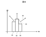
- the normal line can be obtained from, for example, the difference in depth value between adjacent pixels.
- FIG. 8 is a configuration diagram of depth information for explaining a method for obtaining a normal from a depth value.
- a plurality of pixels 80, 82, and 84 are plotted with one line having depth information as the X axis and the depth value as the Z axis, for example, the depth value of the pixel 82 and the depth value of the pixel 84 are A line perpendicular to the connecting line segment 86 can be obtained as the normal line 88. Since the process for obtaining the normal line 88 from the depth values of the pixels 82 and 84 is an operation using a two-dimensional image, the amount of calculation can be reduced as compared with using volume data as it is.
- the GPU 22 functions as a volume rendering unit and a depth information generation unit, inputs light source information, texture information, and texture, inputs depth information generated by the depth information generation unit, and inputs the input information.
- the oil layer image generation unit that generates the oil layer image
- the oil layer image generated by the oil layer image generation unit and the rendering image generated by the volume rendering unit are combined, and the combined image is displayed as a rendered image. It functions as an image composition part to be displayed on the part.
- the volume rendering unit inputs light source information, texture information, and texture, and corrects a rendered image based on the input information.
- the oil layer can be generated based on the light source information and the depth information.
- the effect of the oil layer is added, so the effect of the oil layer is added with high resolution without increasing the amount of calculation.
- a rendered image 30 can be generated.
- This embodiment adds shadows and lighting effects from polygon information, and the configuration of the medical image processing apparatus 10 is the same as that of the first embodiment.
- FIG. 9 is a flowchart for explaining processing for adding a shadow or lighting effect from polygon information. This process is executed by the GPU 22.
- the GPU 22 inputs three-dimensional volume data from the input interface 12 (S51).
- the three-dimensional volume data the same data as in the first embodiment can be used.
- the GPU 22 executes a process for generating depth information based on the three-dimensional volume data (S52), and holds the depth information obtained by this process (S53). At this time, the depth information similar to that in the first embodiment can be used as the depth information.
- the GPU 22 inputs light source information (S54), inputs texture information (S55), and further inputs a texture (S56).
- the input light source information, texture information, texture, and retained depth An oil layer image is generated based on the information (S57).
- the light source information is information indicating the shape, intensity, brightness, position, and orientation of the light source.
- the texture information is information indicating how the light hits.
- the texture is information indicating the pattern and reflection characteristics of the object irradiated with light from the light source.
- the GPU 22 executes a volume rendering process based on the input light source information, the texture information, the texture and the input three-dimensional volume data, and generates a two-dimensional rendering image (S58). Note that after step S58, a target in the rendered image can be specified based on the depth information, and an anti-aliasing process for blurring an edge portion in the specified target can be executed.
- the GPU 22 converts the input volume data into polygons to generate polygon data (S59), holds the generated polygon data (S60), holds the held polygon data, the input light source information, texture information and texture.
- a surface rendering process is executed based on this to generate a two-dimensional surface image (S61).
- the polygon is a polygon composed of a three-dimensional vertex coordinate group having an order. Usually, among the polygons constituting the polygon, a triangle is used as the polygon.
- the GPU 22 synthesizes the generated two-dimensional rendering image with the generated oil layer image and the generated two-dimensional surface image (S62), and the synthesized image is combined with the high-resolution rendering image 30. Is displayed on the display 16 and the processing in this routine is terminated. At this time, the rendered image 30 is displayed on the display 16 as a rendered image to which a shadow or lighting effect is added.
- an oil layer can also be generated based on light source information and depth information.
- a depth value it is also possible to generate a polygon using a method of generating a polygon from volume data such as a marching cube, and to generate a depth value from the generated polygon.
- a polygon rendering method such as a Z-buffer method can be used by using the same virtual viewpoint position and angle of view as in volume rendering.
- the Z-buffer value at the end of rendering is the depth value.
- specular reflection may be realized using a polygon, a virtual viewpoint, a virtual light source, and a shading formula.
- the GPU 22 functions as a volume rendering unit, a depth information generation unit, and an oil layer image generation unit, a polygon generation unit that generates a plurality of polygons from three-dimensional volume data, and generation of the polygon generation unit.
- a surface rendering process is performed on polygon data belonging to each polygon to generate a surface image, an oil layer image generated by the oil layer image generation unit, a rendered image and a surface generated by the volume rendering unit.
- the surface image generated by the rendering unit is combined and functions as an image combining unit that displays the combined image as a rendered image on the display unit.
- a rendered image 30 can be generated.
- the present invention is not limited to the four embodiments described above, and includes various modifications.
- the above-described embodiments have been described in detail for easy understanding of the present invention, and are not necessarily limited to those having all the configurations described. Further, a part of the configuration of one embodiment can be replaced with the configuration of another embodiment, and the configuration of another embodiment can be added to the configuration of one embodiment. Further, it is possible to add, delete, and replace other configurations for a part of the configuration of each embodiment.
- each of the above-described configurations, functions, processing units, processing means, and the like may be realized by hardware by designing a part or all of them with, for example, an integrated circuit.
- Each of the above-described configurations, functions, and the like may be realized by software by interpreting and executing a program that realizes each function by the processor.
- Information such as programs, tables, and files that realize each function is stored in memory, a hard disk, a recording device such as an SSD (Solid State Drive), an IC (Integrated Circuit) card, an SD (Secure Digital) memory card, a DVD ( It can be recorded on a recording medium such as Digital Versatile Disc).
- 10 medical image processing device 12 input / output interface, 14 volume rendering unit, 16 display, 18 memory, 20 CPU, 22 GPU, 24 storage device, 30 rendered image, 32 buttons, 34 numeric input box, 36 slider bar.
Landscapes
- Engineering & Computer Science (AREA)
- Computer Graphics (AREA)
- Physics & Mathematics (AREA)
- General Physics & Mathematics (AREA)
- Theoretical Computer Science (AREA)
- Computer Hardware Design (AREA)
- General Engineering & Computer Science (AREA)
- Software Systems (AREA)
- Architecture (AREA)
- Image Generation (AREA)
- Processing Or Creating Images (AREA)
- Ultra Sonic Daignosis Equipment (AREA)
Abstract
Priority Applications (4)
| Application Number | Priority Date | Filing Date | Title |
|---|---|---|---|
| CN201280078241.7A CN105007824B (zh) | 2012-12-28 | 2012-12-28 | 医用图像处理装置以及图像处理方法 |
| JP2014554043A JP5974376B2 (ja) | 2012-12-28 | 2012-12-28 | 医用画像処理装置および画像処理方法 |
| PCT/JP2012/084214 WO2014103065A1 (fr) | 2012-12-28 | 2012-12-28 | Dispositif de traitement d'images médicales et procédé de traitement d'images |
| US14/655,466 US9830735B2 (en) | 2012-12-28 | 2012-12-28 | Medical image processing device and image processing method |
Applications Claiming Priority (1)
| Application Number | Priority Date | Filing Date | Title |
|---|---|---|---|
| PCT/JP2012/084214 WO2014103065A1 (fr) | 2012-12-28 | 2012-12-28 | Dispositif de traitement d'images médicales et procédé de traitement d'images |
Publications (1)
| Publication Number | Publication Date |
|---|---|
| WO2014103065A1 true WO2014103065A1 (fr) | 2014-07-03 |
Family
ID=51020210
Family Applications (1)
| Application Number | Title | Priority Date | Filing Date |
|---|---|---|---|
| PCT/JP2012/084214 Ceased WO2014103065A1 (fr) | 2012-12-28 | 2012-12-28 | Dispositif de traitement d'images médicales et procédé de traitement d'images |
Country Status (4)
| Country | Link |
|---|---|
| US (1) | US9830735B2 (fr) |
| JP (1) | JP5974376B2 (fr) |
| CN (1) | CN105007824B (fr) |
| WO (1) | WO2014103065A1 (fr) |
Cited By (1)
| Publication number | Priority date | Publication date | Assignee | Title |
|---|---|---|---|---|
| JP2017076295A (ja) * | 2015-10-16 | 2017-04-20 | 富士フイルム株式会社 | 拡張現実提供システム及び方法、情報処理装置、並びにプログラム |
Families Citing this family (9)
| Publication number | Priority date | Publication date | Assignee | Title |
|---|---|---|---|---|
| CN106108944B (zh) * | 2016-06-23 | 2019-07-09 | 飞依诺科技(苏州)有限公司 | 一种超声波三维图像的显示方法及装置 |
| CN106204711B (zh) * | 2016-06-29 | 2020-12-18 | 深圳开立生物医疗科技股份有限公司 | 一种三维容积图像处理方法和系统 |
| CN106203419B (zh) * | 2016-07-25 | 2019-05-07 | 上海肇观电子科技有限公司 | 一种确定包络面的方法和装置 |
| CN107273904A (zh) * | 2017-05-31 | 2017-10-20 | 上海联影医疗科技有限公司 | 图像处理方法及系统 |
| US10628997B2 (en) | 2017-08-24 | 2020-04-21 | Emilio Santos | Method for generating three-dimensional models from constrained sketches and an instruction set |
| US10943390B2 (en) | 2017-11-20 | 2021-03-09 | Fovia, Inc. | Gradient modulated shadow mapping |
| CN109345629A (zh) * | 2018-08-08 | 2019-02-15 | 安徽慧软科技有限公司 | 一种三维医学图像模糊凸显显示方法 |
| US11770517B2 (en) * | 2019-10-28 | 2023-09-26 | Sony Group Corporation | Information processing apparatus and information processing method |
| CN111833427B (zh) * | 2020-07-21 | 2021-01-05 | 推想医疗科技股份有限公司 | 对三维图像进行体绘制的方法及装置 |
Citations (4)
| Publication number | Priority date | Publication date | Assignee | Title |
|---|---|---|---|---|
| JPH07282274A (ja) * | 1994-04-04 | 1995-10-27 | Mitsubishi Electric Corp | グラフィック表示装置 |
| JPH09305797A (ja) * | 1996-05-14 | 1997-11-28 | Matsushita Electric Ind Co Ltd | 三次元レイアウト編集装置 |
| JP2011098191A (ja) * | 2009-10-08 | 2011-05-19 | Toshiba Corp | 超音波診断装置、超音波画像処理装置、超音波画像処理方法、及び超音波画像処理プログラム |
| WO2012101989A1 (fr) * | 2011-01-26 | 2012-08-02 | 株式会社日立メディコ | Dispositif de diagnostic à ultrasons et procédé de traitement d'image |
Family Cites Families (11)
| Publication number | Priority date | Publication date | Assignee | Title |
|---|---|---|---|---|
| JPH09305795A (ja) | 1996-05-15 | 1997-11-28 | Taito Corp | 振り子スクロール装置及び方法 |
| US6549203B2 (en) * | 1999-03-12 | 2003-04-15 | Terminal Reality, Inc. | Lighting and shadowing methods and arrangements for use in computer graphic simulations |
| US6193661B1 (en) * | 1999-04-07 | 2001-02-27 | Agilent Technologies, Inc. | System and method for providing depth perception using single dimension interpolation |
| US8446410B2 (en) * | 2006-05-11 | 2013-05-21 | Anatomage Inc. | Apparatus for generating volumetric image and matching color textured external surface |
| DE102007008767B3 (de) * | 2007-02-22 | 2008-07-24 | Tomtec Imaging Systems Gmbh | Verfahren und Vorrichtung zur Darstellung von 3D Bilddatensätzen auf 2D Bildern |
| US8553046B2 (en) * | 2007-11-09 | 2013-10-08 | Vivante Corporation | Thin-line detection apparatus and method |
| US8290305B2 (en) * | 2009-02-13 | 2012-10-16 | Harris Corporation | Registration of 3D point cloud data to 2D electro-optical image data |
| CN102428501A (zh) * | 2009-09-18 | 2012-04-25 | 株式会社东芝 | 图像处理装置 |
| JP5525930B2 (ja) * | 2010-06-23 | 2014-06-18 | 株式会社日立メディコ | 三次元超音波画像を生成表示する超音波診断装置 |
| US20120154400A1 (en) * | 2010-12-20 | 2012-06-21 | General Electric Company | Method of reducing noise in a volume-rendered image |
| JP5666967B2 (ja) * | 2011-04-08 | 2015-02-12 | 株式会社東芝 | 医用画像処理システム、医用画像処理装置、医用画像診断装置、医用画像処理方法および医用画像処理プログラム |
-
2012
- 2012-12-28 JP JP2014554043A patent/JP5974376B2/ja active Active
- 2012-12-28 CN CN201280078241.7A patent/CN105007824B/zh active Active
- 2012-12-28 US US14/655,466 patent/US9830735B2/en active Active
- 2012-12-28 WO PCT/JP2012/084214 patent/WO2014103065A1/fr not_active Ceased
Patent Citations (4)
| Publication number | Priority date | Publication date | Assignee | Title |
|---|---|---|---|---|
| JPH07282274A (ja) * | 1994-04-04 | 1995-10-27 | Mitsubishi Electric Corp | グラフィック表示装置 |
| JPH09305797A (ja) * | 1996-05-14 | 1997-11-28 | Matsushita Electric Ind Co Ltd | 三次元レイアウト編集装置 |
| JP2011098191A (ja) * | 2009-10-08 | 2011-05-19 | Toshiba Corp | 超音波診断装置、超音波画像処理装置、超音波画像処理方法、及び超音波画像処理プログラム |
| WO2012101989A1 (fr) * | 2011-01-26 | 2012-08-02 | 株式会社日立メディコ | Dispositif de diagnostic à ultrasons et procédé de traitement d'image |
Non-Patent Citations (3)
| Title |
|---|
| "GPU Gems 3 Chapter 14. Advanced Techniques for Realistic Real-Time Skin Rendering", Retrieved from the Internet <URL:http://http.developer.nvidia.com/GPUGems3/gpugems3_chl4.html> * |
| "New 3D Technology", Retrieved from the Internet <URL:http://www.samsung> * |
| ERIK SUNDEN ET AL.: "Image Plane Sweep Volume Illumination", IEEE TRANSACTIONS ON VISUALIZATION AND COMPUTER GRAPHICS, vol. 18, no. 2, December 2011 (2011-12-01), pages 2125 - 2134 * |
Cited By (1)
| Publication number | Priority date | Publication date | Assignee | Title |
|---|---|---|---|---|
| JP2017076295A (ja) * | 2015-10-16 | 2017-04-20 | 富士フイルム株式会社 | 拡張現実提供システム及び方法、情報処理装置、並びにプログラム |
Also Published As
| Publication number | Publication date |
|---|---|
| JPWO2014103065A1 (ja) | 2017-01-12 |
| US9830735B2 (en) | 2017-11-28 |
| US20150379758A1 (en) | 2015-12-31 |
| CN105007824A (zh) | 2015-10-28 |
| JP5974376B2 (ja) | 2016-08-23 |
| CN105007824B (zh) | 2017-07-11 |
Similar Documents
| Publication | Publication Date | Title |
|---|---|---|
| JP5974376B2 (ja) | 医用画像処理装置および画像処理方法 | |
| Kutter et al. | Visualization and GPU-accelerated simulation of medical ultrasound from CT images | |
| JP6147489B2 (ja) | 超音波画像形成システム | |
| KR101353303B1 (ko) | 그래픽 처리 유닛, 그래픽 처리 유닛을 갖춘 영상 처리 장치 및 그래픽 처리 유닛을 이용한 영상 처리 방법 | |
| KR101724360B1 (ko) | 혼합현실 디스플레이 장치 | |
| US9001124B2 (en) | Efficient determination of lighting effects in volume rendering | |
| CA3057216C (fr) | Methode, dispositif et systeme de simulation d'images ombrees | |
| JP2006502508A (ja) | 3dモデリングシステム | |
| JP2009034521A (ja) | 医学的な画像診断におけるデータを体積レンダリングするシステムと方法ならびにコンピュータ読み出し可能記憶媒体 | |
| CN109313821A (zh) | 三维对象扫描反馈 | |
| US9224236B2 (en) | Interactive changing of the depiction of an object displayed using volume rendering | |
| JP7823033B2 (ja) | 組織の区別に基づくbモード画像のレンダリング | |
| US12424332B2 (en) | Unified anisotropic volume and surface mesh storage | |
| JP2008259699A (ja) | 画像処理方法および装置並びにプログラム | |
| US10380786B2 (en) | Method and systems for shading and shadowing volume-rendered images based on a viewing direction | |
| US20220180545A1 (en) | Image processing apparatus, image processing method, and program | |
| CN109754869B (zh) | 着色的超声图像对应的着色描述符的呈现方法和系统 | |
| JP5647398B2 (ja) | 定量的局所測定結果および形態構造の複合4次元プレゼンテーションのための方法および装置 | |
| CN115104129A (zh) | 导航和显示3d图像数据的计算机实现的方法和系统 | |
| Kwon et al. | GPU-accelerated 3D mipmap for real-time visualization of ultrasound volume data | |
| JP6619598B2 (ja) | プログラム、記録媒体、輝度演算装置及び輝度演算方法 | |
| JP7613995B2 (ja) | 超音波診断装置、画像処理装置、およびプログラム | |
| TWI634872B (zh) | 超音波影像之品質改善方法 | |
| Kiss et al. | GPU volume rendering in 3D echocardiography: real-time pre-processing and ray-casting | |
| Ran et al. | Infocarve: A framework for volume visualization on commodity augmented reality displays |
Legal Events
| Date | Code | Title | Description |
|---|---|---|---|
| 121 | Ep: the epo has been informed by wipo that ep was designated in this application |
Ref document number: 12891084 Country of ref document: EP Kind code of ref document: A1 |
|
| ENP | Entry into the national phase |
Ref document number: 2014554043 Country of ref document: JP Kind code of ref document: A |
|
| NENP | Non-entry into the national phase |
Ref country code: DE |
|
| WWE | Wipo information: entry into national phase |
Ref document number: 14655466 Country of ref document: US |
|
| 122 | Ep: pct application non-entry in european phase |
Ref document number: 12891084 Country of ref document: EP Kind code of ref document: A1 |