WO2014103162A1 - バリカンの刃、及びバリカンの刃を備えたバリカン - Google Patents
バリカンの刃、及びバリカンの刃を備えたバリカン Download PDFInfo
- Publication number
- WO2014103162A1 WO2014103162A1 PCT/JP2013/006908 JP2013006908W WO2014103162A1 WO 2014103162 A1 WO2014103162 A1 WO 2014103162A1 JP 2013006908 W JP2013006908 W JP 2013006908W WO 2014103162 A1 WO2014103162 A1 WO 2014103162A1
- Authority
- WO
- WIPO (PCT)
- Prior art keywords
- blade
- movable
- tip
- fixed
- clipper
- Prior art date
- Legal status (The legal status is an assumption and is not a legal conclusion. Google has not performed a legal analysis and makes no representation as to the accuracy of the status listed.)
- Ceased
Links
Images


Classifications
-
- B—PERFORMING OPERATIONS; TRANSPORTING
- B26—HAND CUTTING TOOLS; CUTTING; SEVERING
- B26B—HAND-HELD CUTTING TOOLS NOT OTHERWISE PROVIDED FOR
- B26B19/00—Clippers or shavers operating with a plurality of cutting edges, e.g. hair clippers, dry shavers
- B26B19/02—Clippers or shavers operating with a plurality of cutting edges, e.g. hair clippers, dry shavers of the reciprocating-cutter type
- B26B19/04—Cutting heads therefor; Cutters therefor; Securing equipment thereof
- B26B19/06—Cutting heads therefor; Cutters therefor; Securing equipment thereof involving co-operating cutting elements both of which have shearing teeth
-
- B—PERFORMING OPERATIONS; TRANSPORTING
- B26—HAND CUTTING TOOLS; CUTTING; SEVERING
- B26B—HAND-HELD CUTTING TOOLS NOT OTHERWISE PROVIDED FOR
- B26B19/00—Clippers or shavers operating with a plurality of cutting edges, e.g. hair clippers, dry shavers
- B26B19/38—Details of, or accessories for, hair clippers, or dry shavers, e.g. housings, casings, grips, guards
- B26B19/3846—Blades; Cutters
Definitions
- the present invention relates to a clipper blade having a fixed blade and a movable blade and a clipper having a clipper blade.
- a hair clipper blade for cutting human or animal hair includes a fixed blade having a plurality of blades and a movable blade having a plurality of blades, and the movable blades are overlapped with each other so as to be able to reciprocate. ing.
- This type of clipper requires that the hair be cut short without damaging the skin.
- Patent Document 1 In response to such a request, the technique described in Patent Document 1 is known.
- the fixed blade and the movable blade are overlapped so that the tip of the blade of the fixed blade and the tip of each blade of the movable blade are in sliding contact with each other.
- tip part of a movable blade are formed in the curved surface. Thereby, the damage of the skin is suppressed.
- Patent Document 2 discloses a clipper blade in which resin is applied to the tip of the fixed blade and the tip of the movable blade. That is, the tip portions of the fixed blade and the movable blade are formed into curved surfaces by application of resin. Thereby, the damage of the skin which arises when a front-end
- Patent Document 1 when the movable blade is slid with the tip of the clipper blade pressed against the skin, the skin is sandwiched between the tip of each of the fixed blade and the movable blade. May be damaged.
- the present invention has been made in view of such circumstances, and an object of the present invention is to provide a clipper blade having a low possibility of damaging the skin and excellent in manufacturability, and a clipper provided with the clipper blade. It is in.
- This means comprises: “a fixed blade having a plurality of blades, and a movable blade having a plurality of blades arranged in the same direction as the arrangement of the blades of the fixed blade,
- Each of the blade bodies has a cutting portion having a movable slidable contact surface in contact with the fixed blade, and a blade body tip portion provided on the tip side of the cutting portion, and the blade body of the movable blade
- the distal end portion includes a clipper blade having an inner surface located on the movable blade side with respect to a plane including the movable sliding contact surface.
- the blade body of the movable blade has cutting blade portions provided on both side surfaces of the blade body, and is provided at the tip of the blade body among the cutting blade portions.
- the part that has been made includes a clipper blade having a curved surface or a machined cutting edge.
- each of the blade bodies of the fixed blade is provided with a cutting portion having a fixed sliding contact surface in contact with the movable sliding contact surface, and a tip side of the cutting portion.
- a blade tip, and the blade tip of the fixed blade includes a clipper blade having an inner surface on the fixed blade side with respect to a plane including the fixed sliding contact surface.
- the fixed sliding contact surface of the plurality of blades of the fixed blade has a first tip end edge, and the plurality of blades of the movable blade.
- the movable slidable contact surface includes a clipper blade having a second tip side edge disposed on the base side of the blade body of the movable blade with respect to the first tip side edge.
- the blade tip portion of the movable blade has the inner surface and an outer surface facing the outer surface continuous to the inner surface, and the blade tip portion of the movable blade The tip point on the boundary line between the inner surface and the outer surface exists between the upper surface of the blade tip portion and the movable sliding contact surface, and the distance between the tip point and the upper surface is A clipper blade larger than the distance between the tip point and the movable sliding contact surface ”.
- One mode of the above means includes “a clipper having a clipper blade”.
- the blades and clippers of this clipper are less likely to damage the skin and are excellent in manufacturability.
- FIG. 9 is a cross-sectional view taken along the line CC of FIG. Fig.11 (a) and FIG.11 (b) are the schematic diagrams which show the deformation
- the hair clipper according to the embodiment will be described with reference to FIG.
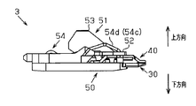
- the clipper 1 includes a main body device 2 and a head portion 3 that can be attached to the main body device 2.
- the main body device 2 includes a drive mechanism 21, a power supply unit 22, a control unit 23 that controls the drive mechanism 21 and the power supply unit 22, and an operation unit 24.
- the drive mechanism 21 reciprocates a movable part (movable blade 40 described later) of the head unit 3, and has an output shaft 21a for transmitting power.
- the drive mechanism 21 includes, for example, a motor and a power transmission mechanism that transmits power of the motor.
- the power supply unit 22 supplies power to the drive mechanism 21.
- the power supply part 22 is comprised by the secondary battery, for example.
- the operation unit 24 switches the operation state of the movable part between the operation state and the stop state.
- the head unit 3 will be described with reference to FIGS.
- the head unit 3 includes a clipper blade 4, a fixed frame 50, a holding frame 51, and a pressing device 54.
- the clipper blade 4 includes a fixed blade 30 and a movable blade 40.
- the fixed blade 30 and the movable blade 40 are overlapped with each other.
- the movable blade 40 is provided so as to be able to reciprocate in a parallel direction (described later) with respect to the fixed blade 30.
- the fixed frame 50 supports the fixed blade 30 from the lower side (the side opposite to the side where the movable blade 40 is disposed in the fixed blade 30).
- the fixed frame 50 holds the fixed blade 30 so as not to be displaced with respect to the fixed frame 50.
- the holding frame 51 holds the movable blade 40 from the upper side (the side opposite to the side where the fixed blade 30 is disposed in the movable blade 40).
- the holding frame 51 holds the movable blade 40 so as not to be displaced with respect to the holding frame 51.
- the holding frame 51 has a plate 52 that is pressed against the movable blade 40.
- the plate 52 is provided with an engaging portion 53 that engages with the output shaft 21 a of the drive mechanism 21. As shown in FIG. 2, the engaging portion 53 includes a fitting portion 53 a that fits with the output shaft 21 a.
- the pressing device 54 presses the movable blade 40 and the plate 52 so that the fixed blade 30 and the movable blade 40 press each other.
- the pressing device 54 includes, for example, two connected torsion springs 54a and 54b (see FIG. 3).
- the pressing device 54 is attached to the fixed frame 50 so that the end portions 54c and 54d of the torsion springs 54a and 54b press the plate 52 and the movable blade 40 toward the fixed blade 30 side.
- the direction from the fixed blade 30 toward the movable blade 40 is referred to as “upward”, and the arrangement in the upward direction when viewed from a predetermined one is referred to as “upper”.
- the direction opposite to the upward direction is referred to as “downward direction”, and the arrangement of the downward direction as viewed from a predetermined object is referred to as “lower side”.
- the fixed blade 30 is disposed above the fixed frame 50.
- a movable blade 40 is disposed above the fixed blade 30.
- the movable blade 40 is held by a holding frame 51.
- the plate 52 of the holding frame 51 is disposed above the movable blade 40.
- Ends 54c and 54d of the torsion spring (pressing device 54) are arranged on the upper side of the plate 52 and push the plate 52 downward. With such a structure, the movable blade 40 is pressed against the fixed blade 30.
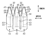
- the fixed blade 30 has a plate-shaped main body 31 (see FIG. 2) and a plurality of blade bodies 32 extending from the main body 31.
- the plurality of blade bodies 32 are arranged in a line at a substantially constant interval.
- the direction in which the blade bodies 32 are arranged is referred to as a “parallel direction”.
- Each blade 32 has a base 33 (see FIG. 6) extending from the main body 31, a cutting part 34 further extending from the base 33, and a blade front end 35 extending further from the cutting part 34.
- the cutting part 34 has a fixed sliding contact surface 34 a (see FIG. 7) that contacts the movable blade 40. As shown in FIG. 6, the cutting portion 34 includes a tapered portion toward the blade tip portion 35 in plan view. That is, the lateral width (length in the parallel direction) of the cutting part 34 gradually decreases toward the blade tip part 35.
- the movable blade 40 has a plate-like main body portion 41 (see FIG. 2) and a plurality of blade bodies 42 extending from the main body portion 41.
- the plurality of blade bodies 42 are arranged in a line at substantially constant intervals.
- Each blade 42 includes a base 43 (see FIG. 6) extending from the main body 41, a cutting portion 44 extending from the base 43, a blade tip 45 extending further from the cutting portion 44, and a cutting blade 48 (FIG. 9).
- the cutting blade portion 48 is provided from the cutting portion 44 to the blade tip portion 45 on each of the side surfaces 42 b of the blade body 42. 5 and 6, the illustration of the cutting blade portion 48 is omitted.
- the base 43 is inclined with respect to the main body 41 (see FIG. 5).
- the cutting part 44 has a plane substantially parallel to the main body part 41.
- the cutting portion 44 has a movable sliding contact surface 44a (see FIG. 7) that is in sliding contact with the fixed blade 30.
- the length of the movable sliding contact surface 44a in the front-rear direction is shorter than the length of the fixed sliding contact surface 34a of the cutting portion 34 of the fixed blade 30 (see FIG. 7).
- the cutting portion 44 has a tapered portion toward the blade tip portion 45 in plan view. That is, the lateral width (length in the parallel direction) of the cutting portion 44 gradually decreases toward the blade tip portion 45.
- the interval (pitch) between the blade bodies 42 of the movable blade 40 and the interval (pitch) between the blade bodies 32 of the fixed blade 30 are different from each other for the following reason.
- each set of blade bodies that come into sliding contact with each other (the blade body 32 of the fixed blade 30 and the blade body of the movable blade 40). 42)
- the timing for cutting the hair is the same.
- the distance (pitch) between the blade bodies 32 of the fixed blade 30 and the distance (pitch) between the blade bodies 42 of the movable blade 40 are intended to avoid simultaneously cutting a large number of hairs. Different.
- FIG. 7 a structure (structure of clipper blade 4) in which the fixed blade 30 and the movable blade 40 are combined will be described.
- the cutting portion 34 of the blade body 32 of the fixed blade 30 and the cutting portion 44 of the blade body 42 of the movable blade 40 are in contact with each other so as to slide on each other.
- the most advanced point 32a of the blade body 32 of the fixed blade 30 and the most advanced point 42a of the blade body 42 of the movable blade 40 substantially coincide with each other in the front-rear direction of the blade bodies 32, 42 in a side view.
- the distance between the most distal point 32a of the blade body 32 of the fixed blade 30 and the most distal point 42a of the blade body 42 of the movable blade 40 in the front-rear direction is referred to as a “step”.
- the step is set to approximately “0”.
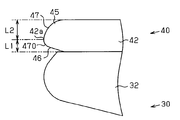
- FIG. 8 is an enlarged view of a portion A in FIG.
- the blade tip portion 35 of the blade body 32 of the fixed blade 30 has an inner surface 36 facing the movable blade 40, an outer surface 37 continuous with the inner surface 36 and facing outward, and a side surface 32 s facing the adjacent blade body 32.
- the outer surface 37 has a curved surface shape.
- the inner surface 36 is continuous with the fixed sliding contact surface 34a and extends to the tip side.
- the inner surface 36 has a flat surface inclined with respect to the fixed sliding contact surface 34a.
- the inner surface 36 is arranged closer to the fixed blade 30 than the reference surface SK1 when a plane (virtual plane) including the fixed sliding contact surface 34a is set as the reference surface SK1.
- the blade body tip portion 45 of the blade body 42 of the movable blade 40 has an inner surface 46 facing the fixed blade 30, an outer surface 47 continuous with the inner surface 46 and facing outward, and a side surface 42 s facing the adjacent blade body 42.
- the side surface 42s constitutes a part of the side surface 42b of the blade body 42.
- the outer surface 47 has a curved surface shape.
- the inner surface 46 is continuous with the movable sliding contact surface 44a and extends to the tip side.
- the inner surface 46 has a flat surface that is inclined with respect to the movable sliding contact surface 44a.
- the inner surface 46 is disposed closer to the movable blade 40 than the reference surface SK2 when a plane (virtual plane) including the movable sliding contact surface 44a is set as the reference surface SK2.
- the blade body tip portion 45 of the blade body 42 of the movable blade 40 has the following configuration.
- the movable slidable contact surface 44a of the blade body 42 of the movable blade 40 is provided on the back side (base 33 side) with respect to the fixed slidable contact surface 34a of the blade body 32 of the fixed blade 30. That is, the front end side edge 44b of the movable slidable contact surface 44a is disposed on the back side (base 43 side) with respect to the front end side end edge 34b of the fixed slidable contact surface 34a in the front-rear direction.
- the gap Sx that is narrower than the gap Sn formed by the two inner surfaces 36, 46 is a fixed sliding contact surface between the inner surface 46 of the blade body 42 of the movable blade 40 and the blade body 32 of the fixed blade 30. 34a.
- the blade body tip portion 45 of the blade body 42 of the movable blade 40 has the following configuration.
- a point on the boundary line 47 a (see FIG. 5) between the inner surface 46 and the outer surface 47 of the blade tip 45, which is the foremost point 47 b in the front-rear direction, is an upper surface 47 c of the blade tip 45. It arrange
- the distance L2 between the tip point 47b and the upper surface 47c is set to a value larger than the distance L1 between the tip point 47b and the movable sliding contact surface 44a. That is, the thickness (length in the vertical direction) (distance L2) of the outer surface 47 of the blade tip 45 is greater than at least half the thickness of the blade tip 45.
- the upper surface 47c of the blade tip 45 is the vertical direction at the intersection of the outer surface 47 and the virtual surface perpendicular to the movable sliding contact surface 44a from the distal end edge 44b of the movable sliding contact surface 44a.
- the surface including the uppermost point and parallel to the movable sliding contact surface 44a (two-dot chain line in FIG. 8).
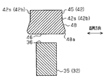
- FIG. 9 is a sectional view taken along line BB in FIG.
- FIG. 10 is a cross-sectional view taken along the line CC of FIG.
- the blade body 42 of the movable blade 40 has cutting edge portions 48 provided on both side surfaces 42b.
- the blade body 42 of the movable blade 40 includes a cutting blade portion 48 that protrudes from each of the side surfaces 42b toward the adjacent side surface (in the parallel direction).
- the blade body 42 of the movable blade 40 has a cutting blade portion 48 that protrudes from each of the side surfaces 42b toward the adjacent side surface (in the parallel direction).
- the 1st part provided in the cutting part 44 among the cutting blade parts 48 has the blade edge 48b which has a sharp shape. That is, as shown in FIG. 9, the lower surface of the cutting blade portion 48 corresponds to an extended surface of the movable sliding contact surface 44a, and the cutting edge 48b of the cutting blade portion 48 has an angle of 90 degrees or less.
- tip part 45 among the cutting blade parts 48 has the blade edge 48a which has a non-sharp shape.
- the cutting edge 48a of the cutting blade portion 48 has a curved surface.
- the inner surface 46 of the blade tip 45 of the movable blade 40 is not in contact with the blade tip 35 of the fixed blade 30. Therefore, the hair clipper blade 4 is not intended to cut hair by sliding between the blade tip portion 45 of the movable blade 40 and the blade tip portion 35 of the fixed blade 30.
- the cutting blade portion 48 provided on the side surface 42 s of the blade tip 45 has a sharp shape, when this portion hits the skin S due to the reciprocating motion of the movable blade 40, the skin S There is a risk of damage. Therefore, the cutting edge 48a of this portion of the cutting edge 48 has a curved surface.
- FIG. 11 shows a deformed state of the skin S when the head portion 3 is pressed against the skin S.
- FIG. 11A shows a deformed state of the skin S in a state where the blade body 32 of the fixed blade 30 and the blade body 42 of the movable blade 40 are arranged in the parallel direction.
- the blade bodies 32 of the fixed blades 30 adjacent to each other and adjacent to each other.
- the skin S enters between the blade bodies 42 of the movable blade 40.
- FIG. 11B shows a deformed state of the skin S in a state where the blade body 32 of the fixed blade 30 and the blade body 42 of the movable blade 40 are not aligned in the parallel direction. That is, the deformation state of the skin S when the blade body 42 of the movable blade 40 is disposed between the blade bodies 32 of the adjacent fixed blades 30 is shown. In this state, the skin S entering from between the blade bodies 32 of the fixed blade 30 and between the blade bodies 42 of the movable blade 40 is pushed back by the movement of the movable blade 40. That is, as shown in FIG. 11A and FIG. 11B, the skin S is between the blade bodies 32 of the fixed blade 30 and between the blade bodies 42 of the movable blade 40 by the reciprocating operation of the movable blade 40. Get in or get pushed back.
- FIGS. 12 and 13 show a state in which the clipper blades 4, 100 are pressed against the skin S, and the skin S is cut along the surface of the blade bodies 32, 42, 132, 142 that contacts the skin S, It is the figure seen from the front-end
- FIG. 12 is a diagram showing a deformed state of the skin S when the skin S enters between the blade body 142 of the movable blade 140 and the blade body 132 of the fixed blade 130 in the clipper blade 100 having a conventional structure.
- the clipper blade 100 of the conventional structure there is no gap Sn between the blade body tip portion 135 of the blade body 132 of the fixed blade 130 and the blade body tip portion 145 of the blade body 142 of the movable blade 140.
- FIG. 13 is a view showing a deformed state of the skin S when the skin S enters between the blade body 42 of the movable blade 40 and the blade body 32 of the fixed blade 30 in the clipper blade 4 according to the present embodiment. is there.
- the skin S has a blade body 132 of the fixed blade 130 and a blade body 142 of the movable blade 140. Remains in a state of being in between. And a part of this skin S is pinched
- the fixed slidable contact surface 34a of the blade tip 35 and the blade tip 45 are located behind the pressing surfaces (outer surfaces 37, 47) that press the skin S at the blade tip 35 and the blade tip 45. Since the movable slidable contact surface 44a exists, the skin S is not easily pinched.
- the clipper blade 4 according to the present embodiment has the following action.
- the outer surface 47 of the blade body tip portion 45 of the blade body 42 of the movable blade 40 has a curved surface and a distance (thickness) L2 that is set so that an area that contacts the skin S is increased.
- the curved surface is less caught on the skin S than the flat surface.
- tip part 45 of the blade 42 of the movable blade 40 presses the skin S is distributed, so that the area which contacts the skin S is large. For this reason, the hair clipper blade 4 has a sharp shape, or damage to the skin S is smaller than that of the blade tip portion having the distance L2 smaller than the distance L1.
- the clipper blade 4 or the clipper 1 of the present embodiment has the following effects.
- the inner surface 46 of the blade body distal end portion 45 of the movable blade 40 is more movable than the plane (reference surface SK2) including the movable sliding contact surface 44a of the movable blade 40.
- the gap Sn is provided between the blade tip 45 of the movable blade 40 and the fixed sliding contact surface 34 a of the fixed blade 30.
- the inner surface 46 of the blade tip 45 of the movable blade 40 and the fixed blade 30 are fixed. Clearances Sn and Sx are provided between the sliding contact surface 34a.
- the clipper blade 4 having the above-described configuration is formed by cutting or the like at the blade tip 45 of the movable blade 40 or the blade tip 35 of the fixed blade 30. That is, since the conventional technique of using a resin to make the tip of the blade tip 45 of the movable blade 40 curved is not easy to manufacture. That is, the blade 4 of the present clipper is excellent in manufacturability as compared with the related art.
- the blade body 42 of the movable blade 40 has cutting blade portions 48 provided on both side surfaces 42b.
- a portion of the blade edge 48a provided at the blade body tip portion 45 has a curved surface.
- a gap Sn is provided between the inner surface 46 of the blade tip 45 of the movable blade 40 and the blade tip 35 of the fixed blade 30, the skin is sandwiched between the skin S of the both blade tips 35 and 45. It is suppressed that S is damaged.
- the tip of the cutting edge portion 48 provided on the side surface 42b of the blade body 42 of the movable blade 40 is sharp, the skin S may be damaged. Therefore, in the above configuration, a part of the cutting blade portion 48 provided at the blade tip 45 has a non-sharp structure, for example, a curved surface. Thereby, the damage of the skin S is suppressed.
- the blade edge 48a of the cutting blade portion 48 provided at the blade body tip portion 45 may have a shape other than a curved surface (see FIG. 18 described later).
- the inner surface 46 of the blade tip 45 is located on the fixed blade 30 side with respect to the plane (reference surface SK1) including the fixed sliding contact surface 34a of the fixed blade 30.
- the gap Sn is provided between the inner surface 46 of the blade tip portion 45 of the movable blade 40 and the inner surface 36 of the blade tip portion 35 of the fixed blade 30.
- the distal end side edge 44b of the movable sliding contact surface 44a of the blade body 42 of the movable blade 40 is the distal end of the fixed sliding contact surface 34a of the blade body 32 of the fixed blade 30. It is arranged closer to the base 43 side of the blade body 42 of the movable blade 40 than the side edge 34b.
- the skin S may be damaged. Therefore, in order to lower the frequency of damaging the skin S, the above configuration is adopted. Thereby, the possibility of damaging the skin S can be reduced.
- the tip point 47b on the boundary line 47a between the inner surface 46 and the outer surface 47 of the blade body tip portion 45 of the movable blade 40 is the upper surface of the blade body tip portion 45. It exists between 47c and the movable sliding contact surface 44a. In such a configuration, the distance L2 between the tip point 47b and the upper surface 47c of the blade tip 45 is larger than the distance L1 between the tip 47b and the movable sliding contact surface 44a of the blade tip 45. .
- the blade tip portion 35 of the fixed blade 30 and the blade tip portion 45 of the movable blade 40 are pressed against the skin S.
- the blade tip 45 of the movable blade 40 is skinned by the reciprocating motion of the movable blade 40.
- the distance L2 between the tip point 47b on the boundary line 47a between the inner surface 46 and the outer surface 47 of the blade tip 45 and the upper surface 47c of the blade tip 45 is defined as the tip point 47b and the movable sliding contact surface.
- the distance L1 is set larger than the distance L1 to 44a. That is, the boundary line 47a between the inner surface 46 and the outer surface 47 is set at the blade tip 45 of the movable blade 40, and the area of the portion that is highly likely to be pressed against the skin S is increased. According to such a configuration, damage (abrasion) of the skin S can be suppressed as compared with a clipper blade in which the distance L2 is set to a length equal to or shorter than the distance L1.
- the clipper 1 of the above embodiment includes the clipper blade 4 having the above-described configuration.
- the hair clipper 1 having this configuration includes the hair clipper blade 4 having the above configuration, the possibility of damaging the skin S when cutting the hair can be reduced.
- the hair clipper 1 includes an embodiment different from the above embodiment.
- the modification of the said embodiment as other embodiment is shown.
- the following modifications can be combined with each other.
- tip part 35 of the fixed blade 30 is arrange
- 36 may be configured as follows. That is, the formation of the inner surface 36 of the blade body tip portion 35 of the fixed blade 30 may be omitted, and the fixed sliding contact surface 34 a may be extended to the blade body tip portion 35. Even in this case, since the gap Sn is provided between the blade tip portion 35 of the fixed blade 30 and the blade tip portion 45 of the movable blade 40, the effect according to the above (1) can be obtained.
- the inner surface 46 of the blade tip 45 of the movable blade 40 has a flat surface, but the form of the inner surface 46 is not limited to this.
- FIG. 14 shows another form of the inner surface 46 of the blade tip 45 of the movable blade 40.
- the inner surface 461 has a concave shape.
- the gap Sn increases between the blade body tip 45 of the movable blade 40 and the fixed sliding contact surface 34 a of the fixed blade 30, so that the skin S can be prevented from being caught.
- FIG. 15 shows still another form of the inner surface 46 of the blade tip 45 of the movable blade 40.
- the inner surface 462 has a curved shape having a raised portion at the center of the surface. In the case of this configuration, there is an effect of pushing back the skin S. Even with such a configuration, the effect according to the above (1) can be obtained.
- FIG. 16 shows still another form of the inner surface 46 of the blade tip 45 of the movable blade 40.
- the inner surface 463 is configured by two surfaces (a first surface 463a and a second surface 463b).
- the inner surface 463 includes a first surface 463a that is substantially perpendicular to the fixed sliding contact surface 34a of the fixed blade 30, and a second surface 463b that is an inclined surface extending from the first surface 463a to the tip side. Even with such a configuration, the effect according to the above (1) can be obtained.
- tip part 45 of the movable blade 40 is this. It is not limited.
- FIG. 17 shows another form of the blade tip 45 of the movable blade 40.
- a boundary portion 470 having a curved surface is provided between the inner surface 46 and the outer surface 47.
- damage (abrasion) of the skin S caused by the movable blade 40 can be suppressed.
- the boundary line 47a between the inner surface 46 and the outer surface 47 does not exist, and therefore the most advanced point 42a of the blade body 42 is used instead of the tip point 47b on the boundary line 47a (see FIG. 8). Using these, the distances L1 and L2 are defined.
- a part of the cutting blade portion 48 provided at the blade tip portion 45 has a curved blade edge 48a.
- 48a is not limited to this shape.
- FIG. 18 shows another form of the cutting edge 48a provided at the blade tip 45 of the cutting edge 48.
- the blade edge 480a has a chamfered portion. Even with such a configuration, damage to the skin S can be suppressed.
- the distance between the most advanced point 32a of the blade body 32 of the fixed blade 30 and the most advanced point 42a of the blade body 42 of the movable blade 40 is set to be substantially “0”.
- this step is not limited to approximately “0”.
- the size of the step is allowed in the range of about 0 to 0.5 mm.
- SYMBOLS 1 ... Hair clipper, 2 ... Main body apparatus, 3 ... Head part, 4 ... Hair clipper blade, 21 ... Drive mechanism, 21a ... Output shaft, 22 ... Power supply part, 23 ... Control part, 24 ... Operation part, 30 ... Fixed blade, DESCRIPTION OF SYMBOLS 31 ... Main-body part, 32 ... Blade body, 32a ... Most advanced point, 32s ... Side surface, 33 ... Base part, 34 ... Cutting part, 34a ... Fixed sliding contact surface, 34b ... Tip side edge, 35 ... Blade body tip part, 36 ... inner surface, 37 ... outer surface, 40 ... movable blade, 41 ... main body, 42 ... blade, 42a ...
- Blade 135,145 ... blade body tip part, 134a, 144a ... sliding contact surface, 135s, 145s ... pressing surface, 461, 462, 463 ... inner surface, 463a ... first surface, 463b ... second surface, 470 ... boundary part, 480a ... blade edge.
Landscapes
- Life Sciences & Earth Sciences (AREA)
- Forests & Forestry (AREA)
- Engineering & Computer Science (AREA)
- Mechanical Engineering (AREA)
- Dry Shavers And Clippers (AREA)
Abstract
肌を損傷させるおそれが小さく、かつ製造性に優れたバリカンの刃およびそのバリカンの刃を備えたバリカンを提供する。バリカンの刃は、複数本の刃体(32)を有する固定刃(30)と、固定刃(30)の刃体(42)の並びと同じ方向に並べられた複数本の刃体(42)を有する可動刃(40)とを備える。可動刃(40)の刃体(42)のそれぞれは、固定刃(30)に接する可動摺接面(44a)を有する切断部(44)と、切断部(44)よりも先端側に設けられた刃体先端部(45)とを有する。可動刃(40)の刃体先端部(45)は、可動摺接面(44a)を含む平面(基準面SK2)よりも可動刃(40)側にある内面(46)を有する。
Description
本発明は、固定刃と可動刃を備えるバリカンの刃及びバリカンの刃を備えたバリカンに関する。
人または動物の毛髪を切断するバリカンの刃は、複数本の刃体を有する固定刃と、複数本の刃体を有する可動刃とを備え、固定刃に対し可動刃が往復運動可能に重ね合わされている。
この種のバリカンでは、肌に損傷を与えることなく毛髪を短く切断することが要求される。
このような要求に対して、特許文献1に記載の技術が知られている。特許文献1に記載のバリカンの刃では、固定刃の刃体の先端部と可動刃の各刃体の先端部とが互いに摺接するように、固定刃と可動刃が重ね合わされている。また、固定刃の先端部と可動刃の先端部はともに曲面に形成されている。これにより、肌の損傷を抑制している。
また、特許文献2には、固定刃の先端部と可動刃の先端部に樹脂が塗布されているバリカンの刃が示されている。すなわち、樹脂の塗布により固定刃及び可動刃のそれぞれの先端部を曲面に形成する。これにより、先端部が肌に擦れることにより生じる肌の損傷を抑制している。
ところで、上記に挙げた2つの特許文献の技術にはそれぞれは次の課題がある。特許文献1の技術では、バリカンの刃の先端部を肌に押し当てた状態で可動刃を摺動させたときに、肌が、固定刃及び可動刃のそれぞれの先端部の間に挟まり、肌が損傷するおそれがある。
特許文献2の技術では、固定刃及び可動刃のそれぞれの先端部に樹脂を塗布するとき、固定刃の摺接面または可動刃の摺接面に樹脂が付着するおそれがある。このように、固定刃の摺接面または可動刃の摺接面に樹脂が付着したときは、毛髪の切断性が低下するため、付着した樹脂を除去する手間が必要になる。
本発明はこのような実情に鑑みてなされたものであり、その目的は、肌を損傷させるおそれが小さく、かつ製造性に優れたバリカンの刃及びそのバリカンの刃を備えたバリカンを提供することにある。
(1)本手段は、「複数本の刃体を有する固定刃と、該固定刃の刃体の並びと同じ方向に並べられた複数本の刃体を有する可動刃とを備え、前記可動刃の前記刃体のそれぞれは、前記固定刃に接する可動摺接面を有する切断部と、前記切断部よりも先端側に設けられた刃体先端部とを有し、前記可動刃の前記刃体先端部は、前記可動摺接面を含む平面よりも前記可動刃側にある内面を有するバリカンの刃」を含む。
この構成によれば、可動刃の刃体と固定刃の刃体とが互いに接近し両刃体の間が狭くなったときにおいて、可動刃の刃体の刃体先端部と固定刃の刃体の刃体先端部との間に隙間が設けられる。このため、両刃体による肌の挟み込みが抑制され、これにより、肌の損傷が抑制される。
(2)上記手段の一態様は、「前記可動刃の前記刃体は、刃体の両側面にそれぞれ設けられた切刃部を有し、前記切刃部のうち前記刃体先端部に設けられている一部分は、曲面有するか、または加工された刃先を有するバリカンの刃」を含む。
(3)上記手段の一態様は、「前記固定刃の前記刃体のそれぞれは、前記可動摺接面に接する固定摺接面を有する切断部と、前記切断部よりも先端側に設けられた刃体先端部とを有し、前記固定刃の前記刃体先端部は、前記固定摺接面を含む平面よりも前記固定刃側にある内面を有するバリカンの刃」を含む。
(4)上記手段の一態様は、「前記固定刃の前記複数本の刃体における前記固定摺接面は、第1の先端側端縁を有し、前記可動刃の前記複数本の刃体における前記可動摺接面は、前記第1の先端側端縁よりも前記可動刃の前記刃体の基部側に配置されている第2の先端側端縁を有するバリカンの刃」を含む。
(5)上記手段の一態様は、「前記可動刃の前記刃体先端部は、前記内面と、該内面に連続する外側を向く外面とを有し、前記可動刃の前記刃体先端部の前記内面と前記外面との間の境界線上の先端点は、前記刃体先端部の上面と前記可動摺接面との間に存在し、前記先端点と前記上面との間の距離は、前記先端点と前記可動摺接面との間の距離よりも大きいバリカンの刃」を含む。
(6)上記手段の一形態は、「バリカンの刃を備えるバリカン」を含む。
本バリカンの刃及びバリカンは、肌を損傷させるおそれが小さく、かつ製造性に優れている。
図1を参照して、実施形態に係るバリカンについて説明する。
図1に示すように、バリカン1は、本体装置2と、本体装置2に装着可能なヘッド部3とを備えている。本体装置2は、駆動機構21と、電源部22と、駆動機構21及び電源部22を制御する制御部23と、操作部24とを備えている。
駆動機構21は、ヘッド部3の可動部品(後述に記載の可動刃40)を往復運動させるものであり、動力を伝達するための出力軸21aを有する。駆動機構21は、例えば、モータ、及びこのモータの動力を伝達する動力伝達機構により構成されている。電源部22は、駆動機構21に電力を供給する。電源部22は、例えば2次電池により構成されている。操作部24は、可動部品の動作状態を運転状態と停止状態との間で切り替える。
図2及び図3を参照して、ヘッド部3について説明する。
図2に示すように、ヘッド部3は、バリカンの刃4と、固定フレーム50と、保持フレーム51と、押圧装置54とを備えている。バリカンの刃4は、固定刃30と可動刃40を備えている。固定刃30と可動刃40とは互いに重ねあわされている。また、可動刃40は、固定刃30に対し並列方向(後述)に往復運動可能に設けられている。
固定フレーム50は、固定刃30を下側(固定刃30において可動刃40が配置される側とは反対側)から支持する。また、固定フレーム50は、当該固定フレーム50に対して位置ずれしないように固定刃30を保持する。
保持フレーム51は、可動刃40を上側(可動刃40において固定刃30が配置される側とは反対側)から保持する。また、保持フレーム51は、当該保持フレーム51に対して位置ずれしないように可動刃40を保持する。保持フレーム51は、可動刃40に押し当てられるプレート52を有する。このプレート52には、駆動機構21の出力軸21aに係合する係合部53が設けられている。係合部53は、図2に示されるように、出力軸21aと嵌合する嵌合部53aを含む。
押圧装置54は、固定刃30と可動刃40とが互いに押圧するように可動刃40及びプレート52を押す。押圧装置54は、例えば、2個の連結された捻りばね54a,54b(図3参照)を含む。捻りばね54a,54bのそれぞれの端部54c,54dがプレート52及び可動刃40を固定刃30側に押すように、押圧装置54は固定フレーム50に取り付けられている。
図4を参照して、ヘッド部3の各部品の配置を説明する。
なお、ヘッド部3の説明において、固定刃30から可動刃40に向く方向を「上方向」といい、所定のものからみて上方向にあるものの配置を「上側」という。上方向の反対方向を「下方向」といい、所定のものからみて下方向にあるものの配置を「下側」という。
固定フレーム50の上側には固定刃30が配置されている。この固定刃30の上側に可動刃40が配置されている。可動刃40は保持フレーム51により保持されている。保持フレーム51のプレート52は可動刃40の上側に配置されている。捻りばね(押圧装置54)の端部54c,54dは、プレート52の上側に配置され、このプレート52を下方向に押す。このような構造により、可動刃40は固定刃30に対して押圧される。
図5及び図6を参照して、固定刃30の構造について説明する。
なお、以降の説明において、刃体32(図6参照)が延びる方向(前後方向)において、物または部分のうち刃体32の先端に近いものを「先端側」にあると言うものとする。
固定刃30は、板状の本体部31(図2参照)と、本体部31から延びる複数本の刃体32とを有する。複数本の刃体32は、略一定の間隔で一列に並べられている。なお、刃体32の並びの方向を、「並列方向」という。
各刃体32は、本体部31から延びる基部33(図6参照)と、基部33から更に先に延びる切断部34と、切断部34から更に先に延びる刃体先端部35とを有する。
切断部34は、可動刃40に摺接する固定摺接面34a(図7参照)を有する。図6に示すように、切断部34は、平面視において刃体先端部35に向かって先細りの部分を含む。すなわち、切断部34の横幅(並列方向の長さ)は、刃体先端部35に向かうにしたがって徐々に減少している。
図5及び図6を参照して、可動刃40の構造について説明する。
可動刃40は、板状の本体部41(図2参照)と、本体部41から延びる複数本の刃体42とを有する。複数本の刃体42は、略一定の間隔で一列に並べられている。固定刃30に対して可動刃40を重ね合わせるようにして組み立てたときは、刃体42の並びの方向が上記の固定刃30の並びの方向(並列方向)と一致する。
各刃体42は、本体部41から延びる基部43(図6参照)と、基部43から延びる切断部44と、切断部44から更に先に延びる刃体先端部45と、切刃部48(図9参照)とを有する。切刃部48は、刃体42の側面42bのそれぞれにおいて切断部44から刃体先端部45に亘って設けられている。なお、図5及び図6では切刃部48の図示を省略している。
基部43は、本体部41に対して傾斜している(図5参照)。切断部44は、本体部41と略平行な平面を有する。
切断部44には、固定刃30に摺接する可動摺接面44a(図7参照)を有する。可動摺接面44aの前後方向の長さは、固定刃30の切断部34の固定摺接面34aの長さよりも短い(図7参照)。切断部44は、平面視において刃体先端部45に向かって先細りの部分を有する。すなわち、切断部44の横幅(並列方向の長さ)は、刃体先端部45に向かうにしたがって徐々に減少する。
可動刃40の刃体42の間隔(ピッチ)と固定刃30の刃体32の間隔(ピッチ)とは、次の理由により、互いに異ならせている。
仮に、固定刃30の刃体32の間隔と可動刃40の刃体42の間隔を等しくしたとき、互いに摺接しあう各組の刃体(固定刃30の刃体32と可動刃40の刃体42)それぞれにおいて、毛髪を切断するタイミングが一致する。この結果、多数の毛髪がこれら刃体32,42の間に入り込むとき、これら多数の毛髪を同時に切断する必要が生じる。これを実現するためには、モータの動力を大きくする必要性が生じる。一方、モータの動力を大きくすることには、本体装置2の大きさの要求から制限がある。このような事情のため、多数の毛髪を同時に切断することを回避することを目的として、固定刃30の刃体32の間隔(ピッチ)と可動刃40の刃体42の間隔(ピッチ)とが異なる。
図7を参照して、固定刃30と可動刃40とを組み合わせた構造体(バリカンの刃4の構造)について説明する。
固定刃30の刃体32の切断部34と可動刃40の刃体42の切断部44とは互いに摺り合うように接する。
固定刃30の刃体32の最先端点32aと可動刃40の刃体42の最先端点42aとは、側面視において、刃体32,42の前後方向で略一致している。なお、以降の説明では、前後方向において、固定刃30の刃体32の最先端点32aと可動刃40の刃体42の最先端点42aとの間の距離を「段差」という。図7の例では、段差は略「0」に設定されている。
図8を参照して、刃体先端部35,45の構造について説明する。図8は、図7のA部の拡大図である。
固定刃30の刃体32の刃体先端部35は、可動刃40に向く内面36と、この内面36に連続し、外側を向く外面37と、隣接する刃体32に面する側面32sとを有する。外面37は、曲面形状を有する。
内面36は、固定摺接面34aと連続しており、先端側にまで延びる。この内面36は、固定摺接面34aに対して傾斜する平坦面を有する。また、内面36は、固定摺接面34aを含む平面(仮想平面)を基準面SK1に設定すると、この基準面SK1よりも固定刃30側に配置されている。
可動刃40の刃体42の刃体先端部45は、固定刃30に向く内面46と、この内面46に連続し、外側を向く外面47と、隣接する刃体42に面する側面42sとを有する。この側面42sは、刃体42の側面42bの一部を構成する。外面47は、曲面形状を有する。
内面46は、可動摺接面44aと連続しており、先端側にまで延びる。この内面46は、可動摺接面44aに対して傾斜する平面を有する。また、内面46は、可動摺接面44aを含む平面(仮想平面)を基準面SK2に設定すると、この基準面SK2よりも可動刃40側に配置されている。
上記構成の2つの内面36、46の構成により、固定刃30の刃体32の刃体先端部35と可動刃40の刃体42の刃体先端部45との間には隙間Snが存在する。この隙間Snの存在により、固定摺接面34a及び可動摺接面44aが、バリカンの刃4の先端よりも奥側(基部33,43側)に配置される。
また、可動刃40の刃体42の刃体先端部45は、次の構成を有する。
可動刃40の刃体42の可動摺接面44aは、固定刃30の刃体32の固定摺接面34aよりも奥側(基部33側)に設けられている。すなわち、可動摺接面44aの先端側端縁44bが、前後方向において、固定摺接面34aの先端側端縁34bよりも奥側(基部43側)に配置される。このような構成により、2つの内面36,46とにより構成される隙間Snよりも更に狭い隙間Sxが、可動刃40の刃体42の内面46と固定刃30の刃体32の固定摺接面34aとの間に存在する。
また、可動刃40の刃体42の刃体先端部45は、次の構成を有する。
刃体先端部45の内面46と外面47との間の境界線47a(図5参照)上の点であって前後方向で最も前方にある先端点47bは、刃体先端部45の上面47cと可動摺接面44aとの間に配置される。そして、先端点47bと上面47cとの間の距離L2は、先端点47bと可動摺接面44aとの間の距離L1よりも大きい値に設定されている。すなわち、刃体先端部45の外面47の厚み(上下方向の長さ)(距離L2)は、少なくとも刃体先端部45の厚みの2分の1よりも大きい。
ここで、刃体先端部45の上面47cとは、可動摺接面44aの先端側端縁44bからこの可動摺接面44aに対して垂直な仮想面と外面47との交線において、上下方向で最も上側にある点を含み、かつ可動摺接面44aに平行な面(図8の2点鎖線)をいう。
図9及び図10を参照して、固定刃30の刃体32及び可動刃40の刃体42の側面構造について説明する。
図9は図8のB-B線に沿った断面図である。図10は、図8のC-C線に沿った断面図である。
可動刃40の刃体42は、両側面42bのそれぞれに設けられた切刃部48を有する。詳しくは、可動刃40の刃体42は、両側面42bのそれぞれから隣接する側面に向かって(並列方向に)突出する切刃部48を有する。可動刃40の刃体42は、両側面42bのそれぞれから、隣接する側面に向かって(並列方向に)突出する切刃部48を有する。
切刃部48のうち切断部44に設けられている第1の部分は、鋭利な形状を有する刃先48bを有する。すなわち、図9に示されるように、切刃部48の下面は、可動摺接面44aの延長面に相当し、切刃部48の刃先48bは90度以下の角度を有する。
切刃部48のうち刃体先端部45に設けられている第2の部分は、非鋭利な形状を有する刃先48aを有する。例えば、図10に示されるように、切刃部48の刃先48aは曲面を有する。
このような切刃部48の構成の採用は次の理由による。
可動刃40の刃体先端部45の内面46は、固定刃30の刃体先端部35に接していない。したがって、このバリカンの刃4では、可動刃40の刃体先端部45と固定刃30の刃体先端部35との摺動により毛髪を切断することは、意図していない。しかし、刃体先端部45の側面42sに設けられている切刃部48が鋭利な形状を有している場合、可動刃40の往復運動によってこの部分が肌Sにあたったとき、肌Sが損傷するおそれがある。そこで、この部分の切刃部48の刃先48aが曲面を有する。
図11~図13を参照して、バリカンの刃4の作用を説明する。
図11は、ヘッド部3を肌Sに押し当てたときの肌Sの変形状態を示す。
図11(a)は、固定刃30の刃体32と可動刃40の刃体42とが並列方向に揃って配置されている状態で、肌Sの変形状態を示す。このように、固定刃30の刃体32と可動刃40の刃体42とが並列方向に揃って配置されているところでは、互いに隣接する固定刃30の刃体32の間、および互いに隣接する可動刃40の刃体42の間に、肌Sが入り込む。
図11(b)は、固定刃30の刃体32と可動刃40の刃体42とが並列方向に揃っていない状態で、肌Sの変形状態を示す。すなわち、隣接する固定刃30の刃体32の間に可動刃40の刃体42が配置されたときの肌Sの変形状態を示す。この状態では、可動刃40の移動により、固定刃30の刃体32の間及び可動刃40の刃体42の間から入り込んだ肌Sは、押し戻されている。すなわち、図11(a)及び図11(b)に示されるように、肌Sは、可動刃40の往復運転により、固定刃30の刃体32の間及び可動刃40の刃体42の間に入り込んだり、押し戻されたりする。
図12及び図13は、バリカンの刃4,100を肌Sに押し当てた状態で、刃体32,42,132,142のうちで肌Sに当接する面に沿って肌Sを切断し、刃体32,42,132,142の先端から基部に向って見た図である。
図12は、従来構造のバリカンの刃100において、可動刃140の刃体142と固定刃130の刃体132との間に肌Sが入り込んだときの肌Sの変形状態を示す図である。なお、従来構造のバリカンの刃100では、固定刃130の刃体132の刃体先端部135と可動刃140の刃体142の刃体先端部145との間に隙間Snが存在していない。
図13は、本実施形態に係るバリカンの刃4において、可動刃40の刃体42と固定刃30の刃体32との間に肌Sが入り込んだときの肌Sの変形状態を示す図である。
図12と図13の比較により次のことが分かる。
従来構造のバリカンの刃100の場合、図12に示すように、両刃体先端部135,145が互いに接近するとき、肌Sが、固定刃130の刃体132と可動刃140の刃体142との間に入り込んだ状態で残存する。そして、両刃体132,142が互いに摺接する部分で、この肌Sの一部が挟まれる。これは、肌Sを押す押圧面135s,145sにまで摺接面134a,144aが延びていることに起因する。
一方、実施形態のバリカンの刃4の場合、図13に示すように、両刃体先端部35,45が互いに接近して、固定刃30の刃体32と可動刃40の刃体42との間に入り込んでいる肌Sは、両刃体先端部35,45が互いに接近するにしたがって徐々に押し戻される。このため、両刃体先端部35,45が互いに摺接する部分に肌Sが入り込まない。これは、両刃体先端部35,45が互いに摺動するときに刃体先端部35及び刃体先端部45との間に隙間Snが存在することに起因する。すなわち、刃体先端部35及び刃体先端部45における肌Sを押す押圧面(外面37,47)よりも、奥側に、刃体先端部35の固定摺接面34a及び刃体先端部45の可動摺接面44aが存在するため、肌Sが挟まれにくくなっている。
また本実施形態に係るバリカンの刃4では、次の作用もある。
上記の可動刃40の刃体42の刃体先端部45の外面47は、曲面を有し、肌Sに当たる面積が大きくなるように設定された距離(厚さ)L2を有する。曲面は、平面に比べると肌Sに対する引っ掛かりが小さい。また、肌Sに当たる面積が大きいほど、可動刃40の刃体42の刃体先端部45が肌Sを押す力が分散される。このため、バリカンの刃4は、鋭利な形状を有するか、または距離L1よりも小さな距離L2を有する刃体先端部に比べて、肌Sに与えるダメージが小さい。
本実施形態のバリカンの刃4またはバリカン1は以下の効果を奏する。
(1)本実施形態に係るバリカンの刃4において、可動刃40の刃体先端部45の内面46は、可動刃40の可動摺接面44aを含む平面(基準面SK2)よりも可動刃40側にある。この構成によれば、可動刃40の刃体先端部45と、固定刃30の固定摺接面34aとの間に隙間Snが設けられる。
すなわち、肌Sの損傷を抑制するために互いに接近する刃体32,42の間に入り込む肌Sの挟み込みを抑制すべく、可動刃40の刃体先端部45の内面46と固定刃30の固定摺接面34aとの間に隙間Sn,Sxが設けられている。
この構成によれば、可動刃40の刃体42と固定刃30の刃体32とが互いに接近し両刃体32,42の間が狭くなったときにおいても、可動刃40の刃体42の刃体先端部45と固定刃30の刃体32の刃体先端部35との間に隙間Sn,Sxが存在する。このため、両刃体32,42による肌Sの挟み込みが抑制され、これにより、肌Sの損傷が抑制される。
なお、上記構成のバリカンの刃4は、可動刃40の刃体先端部45や固定刃30の刃体先端部35は切削加工等により形成される。すなわち、樹脂を用いて可動刃40の刃体先端部45の先端部を曲面にするといった従来技術を用いるものではないため、製造が簡単である。すなわち、本バリカンの刃4は、当該従来技術に比べて製造性に優れている。
(2)本実施形態に係るバリカンの刃4において、可動刃40の刃体42は、両側面42bのそれぞれに設けられた切刃部48を有する。切刃部48のうちで刃体先端部45に設けられている部分の刃先48aが曲面を有する。
可動刃40の刃体先端部45の内面46と、固定刃30の刃体先端部35との間に隙間Snが設けられているため、両刃体先端部35,45の肌Sの挟み込みにより肌Sが損傷することは抑制される。しかし、可動刃40の刃体42の側面42bに設けられている切刃部48の先端が鋭利である場合、肌Sに損傷を与えるおそれがある。そこで、上記構成では、切刃部48のうち刃体先端部45に設けられている一部分が、鋭利でない構造、例えば曲面を有する。これにより、肌Sの損傷を抑制する。なお、刃体先端部45に設けられている切刃部48の刃先48aは、曲面以外の形状を有してもよい(後述の図18参照)。
(3)本実施形態に係るバリカンの刃4において、刃体先端部45の内面46は、固定刃30の固定摺接面34aを含む平面(基準面SK1)よりも固定刃30側にある。
この構成によれば、可動刃40の刃体先端部45の内面46と、固定刃30の刃体先端部35の内面36との間に隙間Snが設けられる。このため、両刃体先端部35,45によって肌Sが挟み込まれる頻度が低くなるため、これにより、肌Sの損傷を抑制することができる。
(4)本実施形態に係るバリカンの刃4において、可動刃40の刃体42における可動摺接面44aの先端側端縁44bは、固定刃30の刃体32における固定摺接面34aの先端側端縁34bよりも、可動刃40の刃体42の基部43側に配置されている。この先端側端縁44bが肌Sに接触すると肌Sが損傷するおそれがある。そこで、肌Sに損傷を与える頻度をより低くするため、上記構成を採用する。これにより、肌Sに損傷を与えるおそれを小さくすることができる。
(5)本実施形態に係るバリカンの刃4において、可動刃40の刃体先端部45の内面46と外面47との間の境界線47a上の先端点47bは、刃体先端部45の上面47cと可動摺接面44aとの間に存在する。このような構成において、先端点47bと刃体先端部45の上面47cとの間の距離L2が、先端点47bと刃体先端部45の可動摺接面44aとの間の距離L1よりも大きい。
可動刃40の刃体先端部45を肌Sに押し当てて毛髪を切断する場合がある。
例えば、毛髪を短く切断するときは、固定刃30の刃体先端部35と可動刃40の刃体先端部45が肌Sに押し当てられる。このような場合、仮に、可動刃40の刃体先端部45のうちで肌Sに押し当てられる部分の面積が小さいと、可動刃40の往復運動により可動刃40の刃体先端部45が肌Sに擦れて、肌Sが損傷(または磨耗)するおそれがある。そこで、刃体先端部45の内面46と外面47との間の境界線47a上の先端点47bと刃体先端部45の上面47cとの間の距離L2を、先端点47bと可動摺接面44aとの間の距離L1よりも大きくする。すなわち、可動刃40の刃体先端部45において、内面46と外面47の境界線47aを設定し、肌Sに押し当てられる可能性が高い部分の面積を大きくする。このような構成によれば、上記距離L2を上記距離L1以下の長さに設定したバリカンの刃に比べて、肌Sの損傷(磨耗)を抑制することができる。
(6)上記実施形態のバリカン1は上記構成のバリカンの刃4を備える。
この構成のバリカン1は、上記構成のバリカンの刃4を備えるため、毛髪を切断するとき、肌Sに損傷を与えるおそれを小さくすることができる。
本バリカン1は、上記実施形態とは別の実施形態を含む。以下、その他の実施形態としての上記実施形態の変形例を示す。なお、以下の各変形例は、互いに組み合わせることもできる。
・本実施形態では、固定刃30の刃体先端部35にある内面36を、固定摺接面34aを含む平面を基準面SK1として、この基準面よりも固定刃30側に配置するが、内面36を次の構成とすることもできる。すなわち、固定刃30の刃体先端部35の内面36の形成を省略して、固定摺接面34aを刃体先端部35まで延長してもよい。この場合でも、固定刃30の刃体先端部35と可動刃40の刃体先端部45との間に隙間Snが設けられるため、上記(1)に準じた効果が得られる。
・本実施形態では、可動刃40の刃体先端部45の内面46が平坦面を有しているが、内面46の形態はこれに限定されない。
図14に、可動刃40の刃体先端部45の内面46の他の形態を示す。この例では、内面461が、凹形状を有する。この構成の場合、可動刃40の刃体先端部45と、固定刃30の固定摺接面34aとの間に隙間Snが大きくなるため、肌Sの挟み込みを抑制することができる。
図15に、可動刃40の刃体先端部45の内面46の更に他の形態を示す。この例では、内面462が、面の中央部分に盛り上がり部を有する曲面形状を有する。この構成の場合、肌Sを押し戻す効果がある。このような構成によっても上記(1)に準じた効果を得ることができる。
図16に、可動刃40の刃体先端部45の内面46の更に他の形態を示す。この例では、内面463を、2つの面(第1面463a及び第2面463b)により構成する。内面463は、固定刃30の固定摺接面34aに対して略垂直な第1面463aと、第1面463aから先端側に延びる傾斜面である第2面463bとを有する。このような構成によっても上記(1)に準じた効果を得ることができる。
・本実施形態では、可動刃40の刃体先端部45の内面46が平坦面を有し、外面47が曲面を有しているが、可動刃40の刃体先端部45の形態がこれに限定されない。
図17に、可動刃40の刃体先端部45の他の形態を示す。この例では、内面46と外面47との間に曲面を有する境界部470が設けられている。この構成の場合、刃体先端部45に角部がなくなるため、可動刃40による肌Sの損傷(磨耗)を抑制することができる。なお、この構成の場合、内面46と外面47との間の境界線47aが存在しなくなるため、境界線47a上(図8参照)の先端点47bに代わり、刃体42の最先端点42aを用いて上記距離L1,L2が定義される。
・本実施形態では、可動刃40の刃体42の切刃部48において、切刃部48のうち刃体先端部45に設けられている一部分は、曲面を有する刃先48aを有するが、当該刃先48aはこの形状に限定されない。
図18に、切刃部48のうち刃体先端部45に設けられている刃先48aの他の形態を示す。この例では、刃先480aは面取り加工された部分を有する。このような構成によっても、肌Sの損傷を抑制することができる。
・本実施形態では、固定刃30の刃体32の最先端点32aと可動刃40の刃体42の最先端点42aとの間の距離、すなわち「段差」が略「0」に設定されているが、この段差は略「0」に限定されない。段差の大きさは、0~0.5mm程度の範囲で許容される。なお、この場合、固定刃30の刃体32の最先端点32aが、可動刃40の刃体42の最先端点42aよりも先方に出ていることが好ましい。これは、逆の構成、すなわち、可動刃40の刃体42の最先端点42aが、固定刃30の刃体32の最先端点32aよりも先方に出ている場合には、固定刃30よりも可動刃40が肌に先に当たり、肌を損傷させるおそれが生じるからである。
1…バリカン、2…本体装置、3…ヘッド部、4…バリカンの刃、21…駆動機構、21a…出力軸、22…電源部、23…制御部、24…操作部、30…固定刃、31…本体部、32…刃体、32a…最先端点、32s…側面、33…基部、34…切断部、34a…固定摺接面、34b…先端側端縁、35…刃体先端部、36…内面、37…外面、40…可動刃、41…本体部、42…刃体、42a…最先端点、42b…側面、42s…側面、43…基部、44…切断部、44a…可動摺接面、44b…先端側端縁、45…刃体先端部、46…内面、47…外面、47a…境界線、47b…先端点、47c…上面、48…切刃部、48a,48b…刃先、50…固定フレーム、51…保持フレーム、52…プレート、53…係合部、53a…嵌合部、54…押圧装置、54a,54b…捻りばね、54c,54d…端部、100…バリカンの刃、130…固定刃、140…可動刃、132,142…刃体、135,145…刃体先端部、134a,144a…摺接面、135s,145s…押圧面、461,462,463…内面、463a…第1面、463b…第2面、470…境界部、480a…刃先。
Claims (6)
- バリカンの刃であって、
複数本の刃体を有する固定刃と、該固定刃の刃体の並びと同じ方向に並べられた複数本の刃体を有する可動刃とを備え、
前記可動刃の前記複数本の刃体のそれぞれは、前記固定刃に接する可動摺接面を有する切断部と、前記切断部よりも先端側に設けられた刃体先端部とを有し、
前記可動刃の前記刃体先端部は、前記可動摺接面を含む平面よりも前記可動刃側にある内面を有する、
バリカンの刃。 - 前記可動刃の前記複数本の刃体のそれぞれは、該刃体の両側面にそれぞれ設けられた切刃部を有し、
前記切刃部のうち前記刃体先端部に設けられている一部分は、曲面を有するか、または面取り加工された刃先を有する、
請求項1に記載のバリカンの刃。 - 前記固定刃の前記複数本の刃体のそれぞれは、前記可動摺接面に接する固定摺接面を有する切断部と、前記切断部よりも先端側に設けられた刃体先端部とを有し、
前記固定刃の前記刃体先端部は、前記固定摺接面を含む平面よりも前記固定刃側にある内面を有する、
請求項1または2に記載のバリカンの刃。 - 前記固定刃の前記複数本の刃体における前記固定摺接面は、第1の先端側端縁を有し、前記可動刃の前記複数本の刃体における前記可動摺接面は、前記第1の先端側端縁よりも前記可動刃の前記刃体の基部側に配置されている第2の先端側端縁を有する、
請求項3に記載のバリカンの刃。 - 前記可動刃の前記刃体先端部は、前記内面と、該内面に連続する外側を向く外面とを有し、
前記可動刃の前記刃体先端部の前記内面と前記外面との間の境界線上の先端点は、前記刃体先端部の上面と前記可動摺接面との間に存在し、
前記先端点と前記上面との間の距離は、前記先端点と前記可動摺接面との間の距離よりも大きい
請求項1~4のいずれか一項に記載のバリカンの刃。 - 請求項1~5のいずれか一項に記載のバリカンの刃を備えるバリカン。
Priority Applications (1)
| Application Number | Priority Date | Filing Date | Title |
|---|---|---|---|
| EP13866943.7A EP2939802B1 (en) | 2012-12-25 | 2013-11-25 | Hair clipper blade, and hair clipper with hair clipper blade |
Applications Claiming Priority (2)
| Application Number | Priority Date | Filing Date | Title |
|---|---|---|---|
| JP2012-281669 | 2012-12-25 | ||
| JP2012281669A JP6016023B2 (ja) | 2012-12-25 | 2012-12-25 | バリカンの刃、及びバリカンの刃を備えたバリカン |
Publications (1)
| Publication Number | Publication Date |
|---|---|
| WO2014103162A1 true WO2014103162A1 (ja) | 2014-07-03 |
Family
ID=51020291
Family Applications (1)
| Application Number | Title | Priority Date | Filing Date |
|---|---|---|---|
| PCT/JP2013/006908 Ceased WO2014103162A1 (ja) | 2012-12-25 | 2013-11-25 | バリカンの刃、及びバリカンの刃を備えたバリカン |
Country Status (3)
| Country | Link |
|---|---|
| EP (1) | EP2939802B1 (ja) |
| JP (1) | JP6016023B2 (ja) |
| WO (1) | WO2014103162A1 (ja) |
Cited By (1)
| Publication number | Priority date | Publication date | Assignee | Title |
|---|---|---|---|---|
| CN110181562A (zh) * | 2019-06-26 | 2019-08-30 | 温州市日电电器有限公司 | 一种剃须刀刀头弹片结构 |
Families Citing this family (9)
| Publication number | Priority date | Publication date | Assignee | Title |
|---|---|---|---|---|
| JP6341379B2 (ja) | 2014-09-30 | 2018-06-13 | パナソニックIpマネジメント株式会社 | トリマーの刃およびこれを備えるトリマー |
| EP3566828A1 (en) * | 2018-05-08 | 2019-11-13 | Koninklijke Philips N.V. | Stationary blade, blade set and hair cutting appliance |
| JP7349682B2 (ja) * | 2020-02-14 | 2023-09-25 | パナソニックIpマネジメント株式会社 | 除毛装置の刃および除毛装置の刃を備える除毛装置 |
| WO2023043629A1 (en) | 2021-09-14 | 2023-03-23 | Wahl Clipper Corporation | Hair clipper bladeset with variable rake angle array tooth geometry |
| USD1099427S1 (en) | 2021-09-14 | 2025-10-21 | Wahl Clipper Corporation | Hair clipper bladeset |
| USD1013267S1 (en) * | 2021-09-22 | 2024-01-30 | Manscaped, Llc | Blade and guard |
| JP7825172B2 (ja) * | 2021-12-06 | 2026-03-06 | パナソニックIpマネジメント株式会社 | バリカンの刃およびバリカン |
| EP4699751A1 (en) | 2024-08-21 | 2026-02-25 | Braun GmbH | Electric hair trimmer for cutting intimate hair |
| EP4699750A1 (en) | 2024-08-21 | 2026-02-25 | Braun GmbH | Electric hair trimmer |
Citations (7)
| Publication number | Priority date | Publication date | Assignee | Title |
|---|---|---|---|---|
| JPS5323690U (ja) * | 1976-08-02 | 1978-02-28 | ||
| JPS548052A (en) * | 1977-06-20 | 1979-01-22 | Matsushita Electric Works Ltd | Blade of electric razor |
| JPS55101286A (en) | 1979-12-28 | 1980-08-01 | Hamasawa Kogyo Kk | Edge shaving edge of electric razor |
| JPS5985166U (ja) * | 1983-08-08 | 1984-06-08 | 日立マクセル株式会社 | 電気かみそりのくし刃 |
| EP0278759A1 (en) * | 1987-02-13 | 1988-08-17 | Lister Shearing Equipment Limited | A clipper blade |
| JPH0241353A (ja) | 1988-08-01 | 1990-02-09 | Mitsui Toatsu Chem Inc | 半導体封止用樹脂組成物 |
| JPH02305590A (ja) * | 1989-05-22 | 1990-12-19 | Tottori Matsuo | 襟刈バリカン |
-
2012
- 2012-12-25 JP JP2012281669A patent/JP6016023B2/ja active Active
-
2013
- 2013-11-25 EP EP13866943.7A patent/EP2939802B1/en active Active
- 2013-11-25 WO PCT/JP2013/006908 patent/WO2014103162A1/ja not_active Ceased
Patent Citations (7)
| Publication number | Priority date | Publication date | Assignee | Title |
|---|---|---|---|---|
| JPS5323690U (ja) * | 1976-08-02 | 1978-02-28 | ||
| JPS548052A (en) * | 1977-06-20 | 1979-01-22 | Matsushita Electric Works Ltd | Blade of electric razor |
| JPS55101286A (en) | 1979-12-28 | 1980-08-01 | Hamasawa Kogyo Kk | Edge shaving edge of electric razor |
| JPS5985166U (ja) * | 1983-08-08 | 1984-06-08 | 日立マクセル株式会社 | 電気かみそりのくし刃 |
| EP0278759A1 (en) * | 1987-02-13 | 1988-08-17 | Lister Shearing Equipment Limited | A clipper blade |
| JPH0241353A (ja) | 1988-08-01 | 1990-02-09 | Mitsui Toatsu Chem Inc | 半導体封止用樹脂組成物 |
| JPH02305590A (ja) * | 1989-05-22 | 1990-12-19 | Tottori Matsuo | 襟刈バリカン |
Cited By (1)
| Publication number | Priority date | Publication date | Assignee | Title |
|---|---|---|---|---|
| CN110181562A (zh) * | 2019-06-26 | 2019-08-30 | 温州市日电电器有限公司 | 一种剃须刀刀头弹片结构 |
Also Published As
| Publication number | Publication date |
|---|---|
| EP2939802A1 (en) | 2015-11-04 |
| EP2939802B1 (en) | 2019-07-03 |
| JP6016023B2 (ja) | 2016-10-26 |
| EP2939802A4 (en) | 2016-01-20 |
| JP2014124261A (ja) | 2014-07-07 |
Similar Documents
| Publication | Publication Date | Title |
|---|---|---|
| WO2014103162A1 (ja) | バリカンの刃、及びバリカンの刃を備えたバリカン | |
| RU2700884C2 (ru) | Режущая головка и устройство для стрижки волос | |
| US9381656B2 (en) | Skin guard for hair trimmer | |
| US9676110B2 (en) | Concaved cutter head assembly for hair trimmer | |
| JP6341379B2 (ja) | トリマーの刃およびこれを備えるトリマー | |
| JP2008142276A (ja) | 電気かみそり | |
| RU2008135061A (ru) | Машинка для стрижки волос | |
| ATE502741T1 (de) | Scherfolie für einen trockenrasierer | |
| WO2019068746A1 (en) | HAIRDRESSER COMB | |
| CN107520862B (zh) | 电动剃刀以及该电动剃刀所使用的外刀 | |
| CN109382852B (zh) | 夹层式结构的刀具及毛发修剪器 | |
| JP5821005B2 (ja) | ヘアーカッター | |
| JP5406769B2 (ja) | 電気かみそり | |
| CN111660327B (zh) | 一种有保护套的推剪刀头及其毛发推剪器 | |
| KR101809256B1 (ko) | 손톱깎이 | |
| WO2013021474A1 (ja) | 爪切り | |
| KR101845380B1 (ko) | 손톱깎이 | |
| US20240286304A1 (en) | Razor cartridge | |
| CN219543258U (zh) | 刀头组件和毛发修剪器 | |
| JP5879531B2 (ja) | 電気かみそり | |
| US12617109B2 (en) | Razor cartridge | |
| EP4711104A1 (en) | Edge guard tooth for a haircutting device | |
| KR100913457B1 (ko) | 손톱깎기 | |
| US20240286303A1 (en) | Razor cartridge | |
| WO2011118684A1 (ja) | 電気かみそり |
Legal Events
| Date | Code | Title | Description |
|---|---|---|---|
| 121 | Ep: the epo has been informed by wipo that ep was designated in this application |
Ref document number: 13866943 Country of ref document: EP Kind code of ref document: A1 |
|
| WWE | Wipo information: entry into national phase |
Ref document number: 2013866943 Country of ref document: EP |
|
| NENP | Non-entry into the national phase |
Ref country code: DE |