WO2014103290A1 - 自走式掃除ロボット - Google Patents
自走式掃除ロボット Download PDFInfo
- Publication number
- WO2014103290A1 WO2014103290A1 PCT/JP2013/007560 JP2013007560W WO2014103290A1 WO 2014103290 A1 WO2014103290 A1 WO 2014103290A1 JP 2013007560 W JP2013007560 W JP 2013007560W WO 2014103290 A1 WO2014103290 A1 WO 2014103290A1
- Authority
- WO
- WIPO (PCT)
- Prior art keywords
- brush
- robot
- self
- cleaning
- plane
- Prior art date
- Legal status (The legal status is an assumption and is not a legal conclusion. Google has not performed a legal analysis and makes no representation as to the accuracy of the status listed.)
- Ceased
Links
Images


Classifications
-
- A—HUMAN NECESSITIES
- A47—FURNITURE; DOMESTIC ARTICLES OR APPLIANCES; COFFEE MILLS; SPICE MILLS; SUCTION CLEANERS IN GENERAL
- A47L—DOMESTIC WASHING OR CLEANING; SUCTION CLEANERS IN GENERAL
- A47L11/00—Machines for cleaning floors, carpets, furniture, walls, or wall coverings
- A47L11/24—Floor-sweeping machines, motor-driven
-
- A—HUMAN NECESSITIES
- A47—FURNITURE; DOMESTIC ARTICLES OR APPLIANCES; COFFEE MILLS; SPICE MILLS; SUCTION CLEANERS IN GENERAL
- A47L—DOMESTIC WASHING OR CLEANING; SUCTION CLEANERS IN GENERAL
- A47L11/00—Machines for cleaning floors, carpets, furniture, walls, or wall coverings
- A47L11/40—Parts or details of machines not provided for in groups A47L11/02 - A47L11/38, or not restricted to one of these groups, e.g. handles, arrangements of switches, skirts, buffers, levers
- A47L11/4036—Parts or details of the surface treating tools
- A47L11/4041—Roll shaped surface treating tools
-
- E—FIXED CONSTRUCTIONS
- E04—BUILDING
- E04G—SCAFFOLDING; FORMS; SHUTTERING; BUILDING IMPLEMENTS OR AIDS, OR THEIR USE; HANDLING BUILDING MATERIALS ON THE SITE; REPAIRING, BREAKING-UP OR OTHER WORK ON EXISTING BUILDINGS
- E04G23/00—Working measures on existing buildings
- E04G23/002—Arrangements for cleaning building facades
-
- F—MECHANICAL ENGINEERING; LIGHTING; HEATING; WEAPONS; BLASTING
- F24—HEATING; RANGES; VENTILATING
- F24S—SOLAR HEAT COLLECTORS; SOLAR HEAT SYSTEMS
- F24S40/00—Safety or protection arrangements of solar heat collectors; Preventing malfunction of solar heat collectors
- F24S40/20—Cleaning; Removing snow
-
- H—ELECTRICITY
- H02—GENERATION; CONVERSION OR DISTRIBUTION OF ELECTRIC POWER
- H02S—GENERATION OF ELECTRIC POWER BY CONVERSION OF INFRARED RADIATION, VISIBLE LIGHT OR ULTRAVIOLET LIGHT, e.g. USING PHOTOVOLTAIC [PV] MODULES
- H02S40/00—Components or accessories in combination with PV modules, not provided for in groups H02S10/00 - H02S30/00
- H02S40/10—Cleaning arrangements
-
- A—HUMAN NECESSITIES
- A47—FURNITURE; DOMESTIC ARTICLES OR APPLIANCES; COFFEE MILLS; SPICE MILLS; SUCTION CLEANERS IN GENERAL
- A47L—DOMESTIC WASHING OR CLEANING; SUCTION CLEANERS IN GENERAL
- A47L2201/00—Robotic cleaning machines, i.e. with automatic control of the travelling movement or the cleaning operation
-
- Y—GENERAL TAGGING OF NEW TECHNOLOGICAL DEVELOPMENTS; GENERAL TAGGING OF CROSS-SECTIONAL TECHNOLOGIES SPANNING OVER SEVERAL SECTIONS OF THE IPC; TECHNICAL SUBJECTS COVERED BY FORMER USPC CROSS-REFERENCE ART COLLECTIONS [XRACs] AND DIGESTS
- Y02—TECHNOLOGIES OR APPLICATIONS FOR MITIGATION OR ADAPTATION AGAINST CLIMATE CHANGE
- Y02E—REDUCTION OF GREENHOUSE GAS [GHG] EMISSIONS, RELATED TO ENERGY GENERATION, TRANSMISSION OR DISTRIBUTION
- Y02E10/00—Energy generation through renewable energy sources
- Y02E10/40—Solar thermal energy, e.g. solar towers
-
- Y—GENERAL TAGGING OF NEW TECHNOLOGICAL DEVELOPMENTS; GENERAL TAGGING OF CROSS-SECTIONAL TECHNOLOGIES SPANNING OVER SEVERAL SECTIONS OF THE IPC; TECHNICAL SUBJECTS COVERED BY FORMER USPC CROSS-REFERENCE ART COLLECTIONS [XRACs] AND DIGESTS
- Y02—TECHNOLOGIES OR APPLICATIONS FOR MITIGATION OR ADAPTATION AGAINST CLIMATE CHANGE
- Y02E—REDUCTION OF GREENHOUSE GAS [GHG] EMISSIONS, RELATED TO ENERGY GENERATION, TRANSMISSION OR DISTRIBUTION
- Y02E10/00—Energy generation through renewable energy sources
- Y02E10/50—Photovoltaic [PV] energy
Definitions
- the present invention relates to a self-propelled cleaning robot. More specifically, the present invention relates to a self-propelled cleaning robot for cleaning the surface of a solar cell array used for solar power generation or a condensing mirror used for solar thermal power generation.
- solar power generation facilities range from facilities with a power generation capacity of about 3 to 4 kilowatts installed in ordinary houses to large-scale power generation facilities with a power generation capacity exceeding 1 megawatt for commercial use. It is expected as an alternative power generation facility.
- solar thermal power generation facilities also have many large-scale facilities having a power generation capacity exceeding 1 megawatt, and are expected as alternative power generation facilities for thermal power generation and nuclear power generation.
- the equipment is installed in a general house, people can also clean it regularly.
- the surface area becomes very large, so it is substantially difficult for a person to clean and remove the dirt on the surface of the solar cell array.
- the total number of solar cell modules reaches 10,000.
- the area of one solar cell module is 1 square meter, the area to be cleaned reaches 10000 square meters.
- a photovoltaic power generation facility a plurality of solar cell arrays each including a plurality of solar cell modules are provided.
- the area of the solar cell array varies depending on various conditions in the field, but is approximately 50. From square meters to 1000 square meters. Accordingly, a large-scale photovoltaic power generation facility requires a self-propelled cleaning robot that can automatically or remotely operate a solar cell array or the like.
- Patent Document 1 a self-propelled cleaning robot that has been reduced in size and weight without providing a suction pump or the like has been developed.
- Patent Document 1 discloses a plurality of brushing brush rollers disposed so as to face a floor surface, a brushing brush roller provided so as to contact the brushing brush roller, and a brushing brush roller And a dust container having an opening on the downstream side in the rotation direction of the scraping brush roller from the contact point of the scraping brush roller is disclosed. Since the robot of Patent Document 1 does not have a suction pump, there is a possibility that the robot can be operated continuously for a certain period of time without mounting a very large battery.
- the robot of Patent Document 1 employs a structure in which the dust pumped up from the floor surface is accommodated in a dust accommodating portion provided in the robot, although no suction pump is provided.
- the dust storage part must also be enlarged in order to store such amount of dust . That is, in the case of the robot of Patent Document 1, although the battery does not need to be increased in size so much, the size of the robot is unavoidable.
- an object of the present invention is to provide a self-propelled cleaning robot that can continuously perform cleaning even in a wide place without increasing the size.
- a self-propelled cleaning robot is a robot that self-travels on a structure having a plane installed outdoors and cleans the plane of the structure, and has a moving means for self-propulsion.
- a rotatable brush comprising a shaft portion and a brush portion provided on the shaft portion, and a cleaning portion provided on a side surface of the robot body.
- An airflow forming cover provided to cover a portion of the brush located on the robot body side and on the opposite side of the plane when the flat surface is cleaned.
- a self-propelled cleaning robot is the first or second aspect of the invention, wherein the cleaning unit includes air supply means for blowing air toward the brush, and an air outlet of the air supply means The airflow forming cover is provided on the inner surface.
- a self-propelled cleaning robot is a robot that self-propels on a structure having a plane installed outdoors and cleans the plane of the structure, and has a moving means for self-propulsion.
- a rotatable brush comprising a shaft portion and a brush portion provided on the shaft portion, and a cleaning portion provided on a side surface of the robot body.
- Air supply means for blowing air toward the brush and in a direction away from the robot body, and the tip of the brush is separated from the robot body when cleaning the plane. It is controlled to rotate in a direction approaching the plane.
- the self-propelled cleaning robot according to a fifth aspect of the present invention is the self-propelled cleaning robot according to the fourth aspect, wherein the cleaning unit covers a portion of the brush located on the robot body side and on the opposite side of the plane when cleaning the plane.
- An airflow forming cover is provided, and an air outlet of the air supply means is provided on the inner surface of the airflow forming cover.
- the self-propelled cleaning robot is the air blower according to any one of the first to fifth aspects, wherein the brush is formed by a pipe having a hollow shaft portion, and blows air to a side surface of the shaft portion.
- the cleaning part is provided with air supply means for supplying air to the shaft part of the brush.
- the plane cleaned by the brush part of a brush can be swept.
- a flow in the direction opposite to the robot body can be formed by the air flow generated by the rotation of the airflow forming cover and the brush portion of the brush.
- dust or the like removed from the plane by the brush can be blown off by the air flow.
- the plane can be cleaned without collecting the dust removed by sweeping from the plane. Therefore, it is not necessary to provide a part for collecting dust in the robot body, so that the robot body does not increase in size.
- it is not necessary to suck dust there is no need to provide a suction pump or the like.
- the air flow formed only by the rotation of the brush portion of the brush is also in the direction opposite to the robot body. Therefore, the effect of blowing off dust removed from the flat surface by the brush can be strengthened.
- the air flow supplied from the air outlet of the air supply means can be applied to the brush, dust attached to the brush can be removed by this air flow. Then, it can prevent that the effect which cleans the plane by a brush falls.
- the fourth aspect if the brush is rotated, the plane to be cleaned by the brush portion of the brush can be swept.
- the robot is controlled by the air flow generated by the rotation of the airflow forming cover and the brush portion of the brush.
- a flow in the direction opposite to the main body can be formed.
- dust or the like removed from the plane by the brush can be blown off by the air flow.
- the air outlet of the air supply means is provided on the inner surface of the airflow forming cover, the flow of air supplied from the air outlet can be reliably applied to the brush.
- the sixth invention if the air is blown out from the outlet, the air can be reliably applied to the brush portion of the brush, so that the effect of cleaning the brush portion can be enhanced.
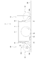
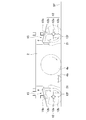
- FIG. 3 is a sectional view taken along line III-III in FIG. 1.
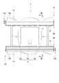
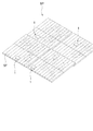
- FIG. 1 It is a schematic front view of the self-propelled cleaning robot 1 of the present embodiment.
- structure SP which the self-propelled cleaning robot 1 of this embodiment cleans.
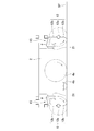
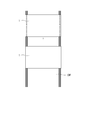
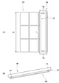
- FIG. sectional drawing of the self-propelled cleaning robot 1 of other embodiment It is a schematic explanatory drawing of the condition where the self-propelled cleaning robot 1 of this embodiment cleans a solar cell module.
- the self-propelled cleaning robot of the present invention is a robot for cleaning a planar portion of a structure installed outdoors, and can perform a long-time cleaning operation while being small and lightweight. It has the feature in doing so.
- the structure to be cleaned by the self-propelled cleaning robot of the present invention is a structure having a flat surface, and any structure that allows the self-propelled cleaning robot 1 to move along the flat surface is particularly limited.
- a solar cell array in a large-scale photovoltaic power generation facility, a condensing mirror in a solar thermal power generation facility, a solar water heater, and the like can be given.
- the plane to be cleaned can include the surface of the solar cell array (that is, the light receiving surface of the solar cell module), the surface of the collector mirror (that is, the light receiving surface of the mirror), and the light receiving surface of the solar water heater.
- the plane is a concept including a plane as a flat surface such as a solar cell array and a curved surface having a large curvature radius and almost flat like a collector mirror.
- a solar cell array, a condensing mirror in a solar power generation facility, and a solar water heater are referred to as a structure SP.
- the surface (namely, each said light-receiving surface) of structure SP used as the object cleaned is called object plane SF (refer FIG. 5).
- the self-propelled cleaning robot 1 of the present embodiment is provided with a robot body 2 having a moving mechanism for traveling on a target plane SF of a structure SP, and the robot body 2.
- the robot body 2 includes a moving mechanism 4 for moving the self-propelled cleaning robot 1 along the target plane SF of the structure SP to be cleaned.
- the moving mechanism 4 includes a pair of side drive wheels 4a and 4a and one intermediate drive wheel 4b. Specifically, the pair of side drive wheels 4a and 4a and the intermediate drive wheel 4b are arranged to form a triangle in plan view (see FIG. 1). For this reason, the self-propelled cleaning robot 1 can be stably arranged on the target plane SF.
- the pair of side drive wheels 4a and 4a employs general wheels that can only rotate around the rotation axis, but the intermediate drive wheel 4b employs omni wheels (omnidirectional wheels). Yes.
- all the drive wheels 4a and 4b of the moving mechanism 4 are connected to drive motors, respectively, so that each drive motor can independently drive the drive wheels 4a and 4b. All the drive motors have their rotational speeds controlled by a control unit provided in the robot body 2. For this reason, if the rotation speed of each drive motor is controlled by the control unit, the self-propelled cleaning robot 1 can be moved linearly or turned.
- the front-rear direction of the self-propelled cleaning robot 1 is referred to as the front-rear direction of the self-propelled cleaning robot 1.
- each drive motor is controlled by the control unit, and the movement of the self-propelled cleaning robot 1 is controlled.
- the movement path of the self-propelled cleaning robot 1 may be stored in the control unit and automatically moved on the target plane SF along the movement path. Further, the movement may be controlled by supplying a signal to the control unit from the outside. For example, the movement of the self-propelled cleaning robot 1 may be controlled by remote control using a remote controller or the like.
- the drive wheels 4 are not limited to the above-described configuration, and may be configured so that the self-propelled cleaning robot 1 can be moved linearly or turned.
- the omni wheel that is the intermediate drive wheel 4b may not be used as a drive wheel, but only a pair of drive wheels 4a and 4a may be used as drive wheels.
- a passive wheel may be employed for the intermediate drive wheel 4b.
- the moving direction of the self-propelled cleaning robot 1 can be freely changed by adjusting the rotational speeds of the pair of drive wheels 4a and 4a.
- the pair of cleaning parts 10, 10 are provided in front of and behind the robot body 2, respectively.
- the cleaning part 10 located in front of the robot main-body part 2 (FIG. 2 and the right side in FIG. 3) is demonstrated.
- the cleaning unit 10 is connected to the robot body 2 by a frame 11.
- the cleaning unit 10 includes a brush 12.
- the brush 12 includes a shaft portion 12 a and a pair of brush portions 12 b and 12 b provided on the outer peripheral surface of the shaft portion 12.
- Both ends of the shaft portion 12a are rotatably supported by the frame of the cleaning unit 10. Moreover, when the self-propelled cleaning robot 1 is placed on the target plane SF, the axial direction thereof is provided so as to be substantially parallel to the target plane SF.
- the pair of brush portions 12b and 12b are formed by arranging a plurality of brushes along the axial direction.
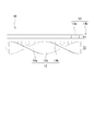
- Each brush portion 12b is provided such that the position of the brush is displaced along the circumferential direction as it moves in the axial direction of the shaft portion 12a (see FIGS. 1 and 4).
- each brush portion 12b is formed in a spiral shape on the side surface of the shaft portion 12a.
- the pair of brush portions 12b and 12b are arranged to form a double helix. That is, the pair of brush portions 12b and 12b are formed such that the brushes of the pair of brush portions 12b and 12b are rotated 180 degrees with respect to each other in the cross section orthogonal to the axial direction of the shaft portion 12a. (See FIG. 3).
- the cleaning part 10 is provided with the brush drive part 13 which rotates the axial part 12a of the brush 12 around an axis
- the brush drive unit 13 includes a brush drive motor 13a, and the main shaft of the brush drive motor 13a is connected to the end of the shaft 12a of the brush 12 by a belt pulley mechanism 13b.
- the operating state of the brush drive motor 13a is controlled by the control unit. Therefore, when the brush drive motor 13a is operated, the driving force is transmitted to the shaft portion 12a of the brush 12 via the belt pulley mechanism 13b, and the brush 12 can be rotated.
- the brush drive motor 13a is arranged so that the tip of the brush portion 12b of the brush 12 approaches the target plane SF while being separated from the robot body 2 in a state where the self-propelled cleaning robot 1 is placed on the target plane SF. It is controlled to rotate (the direction of the arrow in FIGS. 2 and 3). That is, in FIGS. 2 and 3, the brush 12 of the cleaning unit 10 located on the front side (right side) of the robot body 2 rotates counterclockwise and the cleaning located on the rear side (left side) of the robot body 2. The operation of the brush drive motor 13a is controlled so that the brush 12 of the section 10 rotates clockwise.
- the cleaning part 10 is provided with the airflow formation cover 15 between the brush 12 and the front surface of the robot main-body part 2.
- the airflow forming cover 15 is a member that extends along the axial direction of the shaft portion 12 a of the brush 12 and is provided so as to cover a part of the brush 12.
- the airflow forming cover 15 is provided so as to cover a portion above the brush 12 from a portion of the brush 12 on the robot body 2 side (that is, a portion located on the opposite side to the target plane SF).
- this airflow formation cover 15 is formed so that the surface by the side of the brush 12 may become a surface dented from the brush 12 side.
- it has an opening on the brush 12 side, and is formed in a substantially C shape in a sectional view or a substantially reverse letter shape in a sectional view.
- the object plane SF can be cleaned as follows.
- the self-propelled cleaning robot 1 of the present embodiment is placed on the target plane SF. Then, all the drive wheels 4 are disposed in contact with the target plane SF (see FIGS. 2 and 3).
- the target plane SF can be sequentially swept by the brush portion 12b of the brush 12. Then, with the movement of the self-propelled cleaning robot 1, the target plane SF can be sequentially cleaned (see FIG. 7).
- the self-propelled cleaning robot 1 of the present embodiment only the target plane SF is swept by the brush portion 12b of the brush 12, and no mechanism for collecting the swept dust is provided. For this reason, the dust etc. of the part (sweep part) which the brush part 12b of the brush 12 contacted only floats up from the object plane SF.
- the cleaning unit 10 is rotated in a direction in which the tip of the brush unit 12b of the brush 12 approaches the target plane SF while being separated from the robot body 2. Then, on the target plane SF side (downward) with respect to the shaft portion 12a of the brush 12, an air flow (blowout flow) outward from the robot body 2 is generated with the movement of the brush portion 12b. For this reason, dust and the like floating from the target plane SF are blown away outward from the sweeping portion by the blowing flow, so that the surface of the sweeping portion can be in a state with little dust.
- an air flow toward the robot body 2 is generated above the shaft portion 12a of the brush 12. Then, this air flow is returned to the air flow from the robot body 2 outward by the airflow forming cover 15 (see arrow a in FIG. 3). That is, the airflow forming cover 15 enhances the blowing flow. Then, dust and the like floating from the target plane SF are blown farther from the sweeping portion by this blowing flow, so that it is possible to prevent the vicinity of the sweeping portion from being contaminated by the blown dust and the like.
- the dust blown off will eventually fall, but since the dust is diffused by the blowout flow, only a small amount of dust will fall in each place. Moreover, since the dust blown off is further diffused by the wind or the like, even when the dust is scattered, the surrounding dirt is in a state where the dirt is less than that of the sweeping part before the brush part 12b of the brush 12 contacts. Become. Therefore, it is possible to prevent other parts from becoming dirty by blowing off dust and the like as described above. Then, the target plane SF can be cleaned without collecting dust removed by sweeping from the target plane SF. And since it is not necessary to provide the robot main body 2 with the part which collects dust, the robot main body 2 is not enlarged. In addition, since it is not necessary to suck dust or the like, the power consumption for operating the self-propelled cleaning robot 1 can be reduced, so that cleaning of a very large place can be continuously performed.
- the target plane SF is the surface of a solar cell array of a large-scale photovoltaic power generation facility installed in a desert or an area where volcanic ash falls, dust accumulated on the surface is fine sand or the like.
- the shade that hinders power generation from occurring it is normal that no obstructing buildings or the like are arranged around the place where the power is installed. For this reason, the wind is blowing strongly around the large-scale photovoltaic power generation facility.
- the self-propelled cleaning robot 1 of this embodiment if sand or the like on the surface of the solar cell array is cleaned by the self-propelled cleaning robot 1 of this embodiment, and sand or ash is once peeled off from the surface of the solar cell array and blown away, the action of wind or the like can be achieved. With the help, sand and the like can be diffused far away, and the surface of the solar cell array can be sequentially made dust-free. And since self-propelled cleaning robot 1 can reduce power consumption for cleaning, work can be performed continuously for a long time. Therefore, the cleaning of the solar cell array of the large-scale photovoltaic power generation facility as described above can be performed efficiently.
- the rotation direction of the brush 12 is rotated in the above-described direction, the efficiency of removing dust and the like can be increased, but the rotation direction of the brush 12 may be rotated in the opposite direction.
- an air flow toward the robot body 2 is generated below the shaft portion 12 a of the brush 12, so that dust or the like lifted by the brush 12 flows into the airflow forming cover 15.
- the dust floating from the plane can be finally scattered outward.
- the airflow forming cover 15 has its tip only extending to above the shaft of the brush 12, but the position of the tip of the airflow forming cover 15 is not particularly limited. However, the wider the area where the upper part of the brush 12 is covered by the airflow forming cover 15, the higher the airflow forming effect due to the rotation of the brush 12. Therefore, it is preferable that the airflow forming cover 15 is provided so as to cover the entire upper portion of the brush 12 (see FIG. 6). For example, as shown in FIG. 6, the tip of the airflow forming cover 15 may be extended to a position where the tip of the brush 12 is farthest from the robot body 2.
- a blade 12f may be provided on the shaft portion 12a of the brush 12 in addition to the brush portion 12b (see FIG. 6). If the blade 12f is provided, an air flow can be formed not only by the brush portion 12b but also by the blade 12f, so that the air flow formed by the rotation of the brush 12 can be strengthened. Since it is desirable to provide the blade 12f so as not to interfere with the brush portion 12b of the brush 12, when the brush portion 12b of the brush 12 is provided in a spiral shape as in the above example, the blade 12f is also spiraled. It is desirable to provide in a shape. The shape of the blade 12f is not particularly limited as long as the airflow can be formed by the rotation of the brush 12.
- the blade 12f can be formed by standing a plate-like member on the shaft portion 12a.
- the length of the plate-like member (the length in the radial direction of the shaft portion 12a) is not particularly limited, but is preferably long enough not to obstruct the cleaning by the brush portion 12b. For example, if it is about half the length of the brush portion 12b, a sufficient airflow forming effect can be obtained.
- the position and number of the blades 12f are not particularly limited. For example, as shown in FIG. 6, if one (that is, two) is provided in the middle of the pair of brush portions 12b, 12b in the circumferential direction of the shaft portion 12a, the air flow is prevented while preventing the weight of the brush 12 from increasing. The formation effect can be sufficiently enhanced.
- Air supply means 20 Further, an air supply means 20 that blows air toward the brush 12 may be provided. In this case, the flow of air supplied from the air supply means 20 can be applied to the brush portion 12 b of the brush 12. Then, dust and the like attached to the brush portion 12b of the brush 12 can be removed by this air flow, so that the brush portion 12b of the brush 12 can be maintained in a clean state. Then, the fall of the effect which cleans the object plane SF by the brush part 12b of the brush 12 can be prevented.
- the structure of the air supply means 20 is not particularly limited, for example, a plurality of fans 21 can be provided on the inner wall of the airflow forming cover 15 to form the air flow as described above. Further, an air discharge port may be provided instead of the plurality of fans 21, and air may be supplied to the air discharge port from an air supply means such as a blower via a duct.
- air when air is supplied from an air supply means such as a blower, air may be blown from the shaft portion 12a of the brush 12 toward the brush portion 12b.
- an air supply means such as a blower
- air may be blown from the shaft portion 12a of the brush 12 toward the brush portion 12b.
- a hollow pipe is adopted as the shaft portion 12a, and a blowout port is provided on the side surface. Then, if air is supplied into the pipe from the shaft end of the shaft portion 12a, the air can be blown out from the outlet. Then, since air can be reliably applied to the pair of brush portions 12b, 12b of the brush 12, the effect of cleaning the brush portion 12b can be enhanced.
- a member for squeezing the brush portion 12b of the brush 12 may be provided.
- the ironing member 15b is provided inside the airflow forming cover 15, when the brush 12 rotates, the brush portion 12b always comes into contact with the ironing member 15b during one rotation. Sand attached to the brush portion 12b can be removed.
- the position, shape, and installation method of the ironing member 15b are not particularly limited, but the ironing member 15b is used to prevent the airflow forming effect of the airflow forming cover 15 from being reduced by providing the ironing member 15b.
- the length of the brush which comprises a pair of brush parts 12b and 12b is not specifically limited.
- the self-propelled cleaning robot 1 When the self-propelled cleaning robot 1 is placed on the target plane SF, it is only necessary to have a length that allows the tip of the brush to contact the target plane SF.
- the length of the brush is preferably about 45 to 47 mm.
- this is determined in accordance with other parameters of the robot such as the rigidity of the brush, and needless to say, it is not limited to the above-mentioned dimensions.
- each brush part 12b does not need to arrange
- the brush may be arranged so as to be aligned along the axial direction of the shaft portion 12b, and is not particularly limited.
- the self-propelled cleaning robot 1 described above sequentially has the surface of each structure in a structure SP composed of a plurality of structures like a solar cell array composed of a plurality of solar cell modules. Suitable for cleaning.
- the above-described self-propelled cleaning robot 1 can simultaneously clean the surfaces of a plurality of structures constituting the structure SP, such as a solar cell array including a plurality of solar cell modules. If the traveling cleaning robot 1 has the following structure, cleaning becomes easier.
- the structure of the structure SP that is cleaned by the following self-propelled cleaning robots 1B to 1D is not particularly limited. However, it is a structure SP such as a solar cell array formed by arranging a plurality of structures such as solar cell modules in a lattice pattern, and is suitable for a structure SP formed to be longer in the horizontal direction than in the vertical direction. Yes.
- the vertical direction (that is, the direction in which the length is short) of the structure SP is referred to as the minor axis direction of the structure SP.
- the basic structure of the following self-propelled cleaning robots 1B to 1D is substantially the same as that of the above-described self-propelled cleaning robot 1, the following configuration is different from that of the self-propelled cleaning robot 1. Only the part which has is demonstrated.
- the self-propelled cleaning robot 1 ⁇ / b> B has a longer width (that is, the axial direction of the brush 12 in the cleaning unit 10) than the self-propelled cleaning robot 1.
- the length of the brush 12 in the axial direction is longer than the length AL of the structure SP in the short axis direction (hereinafter simply referred to as the length AL of the structure SP). That is, the length of the brush 12 in the axial direction is set to such a length that the brush portion 12b of the brush 12 is in contact with the entire plurality of structures of the structure SP.
- the self-propelled cleaning robot 1B In the case of the self-propelled cleaning robot 1B having such a structure, the self-propelled cleaning robot 1 is placed on the target plane SF, and the axial direction of the brush 12 is made to coincide with the short axis direction of the structure SP. If the drive wheel 4a of the moving mechanism 4 is operated from this state, the self-propelled cleaning robot 1B can be moved in the width direction of the structure SP (in the left-right direction in FIG. 8). Can be cleaned.
- a self-propelled cleaning robot 1C shown in FIG. 9 is obtained by providing the above-described self-propelled cleaning robot 1B with an edge roller 4e, and other configurations are substantially the same as those of the self-propelled cleaning robot 1B. Is.
- the edge roller 4e is provided at a position in contact with the upper edge of the structure of the structure SP when the self-propelled cleaning robot 1C is disposed on the structure SP. That is, the self-propelled cleaning robot 1C is in a state of being caught on the structure SP by the edge roller 4e. For this reason, 1 C of self-propelled cleaning robots can be arrange
- the edge roller 4e is provided so that the rotation axis thereof is parallel to the target plane SF, and the structure of the structure SP when the self-propelled cleaning robot 1C moves in the width direction of the structure SP. It can be rolled on the upper edge. For this reason, even if the edge roller 4e is provided, the self-propelled cleaning robot 1C can move smoothly on the target plane SF of the structure SP.
- a self-propelled cleaning robot 1D shown in FIG. 10 is provided with a pair of movable legs 2cf and 2cf on the robot body 2 of the self-propelled cleaning robot 1B described above, and is driven by drive wheels 4f of the pair of movable legs 2cf and 2cf.
- the other configurations are substantially the same as those of the self-propelled cleaning robot 1B.
- the pair of moving legs 2cf, 2cf are provided at both ends in the width direction of the robot body 2.
- the robot body 2 (in other words, the axial direction of the brush 12 in the cleaning unit 10) is the structure SP.
- the length of each moving leg 2cf is adjusted so that the brush portion 12b of the brush 12 of the cleaning unit 10 is in contact with the target plane SF of the structure SP in parallel with the target plane SF.
- the pair of moving legs 2cf, 2cf includes a drive wheel 4f at the lower end thereof.
- the drive wheels 4f are provided so as to roll in a direction perpendicular to the axial direction of the brush 12.
- the self-propelled cleaning robot 1D provided with a pair of moving legs 2cf and 2cf is disposed so as to straddle the structure SP, and the axial direction of the brush 12 coincides with the short axis direction of the structure SP. If arranged, the self-propelled cleaning robot 1D can be moved in the width direction of the structure SP (left and right in FIG. 8) along the target plane SF of the structure SP, and a plurality of structures are simultaneously cleaned. be able to.
- the cleaning unit 10 may be movable with respect to the robot body 2.
- both end portions of the cleaning unit 10 (end portions in the left-right direction in FIG. 10B) are connected to the robot main body unit 2 via an elevating unit 2sb such as an air cylinder or a screw mechanism.
- an elevating unit 2sb such as an air cylinder or a screw mechanism.
- the self-propelled cleaning robot 1C having the pair of moving legs 2cf and 2cf is disposed so as to straddle the structure SP and the lifting unit 2sb is operated, the object plane SF of the structure SP is cleaned.
- the part 10 can be moved closer to and away from.
- the structure of the brush portion 12b of the brush 12 of the cleaning unit 10 and the structure can be adjusted by adjusting the operation of the elevating unit 2sb.
- the contact state of the object SP with the target plane SF can be made a state suitable for cleaning.
- the contact state between the brush portion 12b of the brush 12 and the target plane SF of the structure SP (that is, the operation amount of the elevating unit 2sb) is the distance between the cleaning unit 10 and the target plane SF by a contact sensor or a non-contact sensor. May be measured, and the operation of the elevating unit 2sb may be controlled based on the measured value.
- the elevating part 2sb there is a function of lifting the cleaning part 10, but it is also possible to use a thing that descends by the weight of the cleaning part 10 when lifting is released.
- the cleaning unit 10 if a pair of driven wheels 10b and 10b are provided at both ends of the cleaning unit 10, the cleaning unit 10 is moved until both the pair of driven wheels 10b and 10b come into contact with the target plane SF of the structure SP. Descend. Therefore, even if there is no special sensor, the brush portion 12b of the brush 12 and the target plane SF of the structure SP can be in a predetermined contact state.
- a mechanism for pressing the cleaning unit 10 against the target plane SF of the structure SP with a predetermined biasing force in a state where the cleaning unit 10 is lowered may be provided.
- an urging means such as a spring may be provided between the cleaning unit 10 and the robot body 2.
- the cleaning unit 10 that is, the brush portion 12b of the brush 12
- the distance from the SF is kept substantially constant.
- the cleaning unit 10 can be moved along the target plane SF while maintaining a substantially constant contact state between the brush portion 12b of the brush 12 and the target plane SF of the structure SP. Stable cleaning can be performed.
- the self-propelled cleaning robot of the present invention is suitable as a robot for cleaning a solar cell array of a large-scale photovoltaic power generation facility, a condensing mirror of a solar thermal power generation facility, a light receiving surface in a solar water heater, and the like.
Landscapes
- Engineering & Computer Science (AREA)
- Architecture (AREA)
- Mechanical Engineering (AREA)
- Chemical & Material Sciences (AREA)
- Physics & Mathematics (AREA)
- Sustainable Energy (AREA)
- Civil Engineering (AREA)
- Structural Engineering (AREA)
- Chemical Kinetics & Catalysis (AREA)
- Life Sciences & Earth Sciences (AREA)
- Sustainable Development (AREA)
- Electrochemistry (AREA)
- Thermal Sciences (AREA)
- Combustion & Propulsion (AREA)
- General Engineering & Computer Science (AREA)
- Cleaning In General (AREA)
- Electric Vacuum Cleaner (AREA)
- Photovoltaic Devices (AREA)
Abstract
Description
例えば、太陽光発電施設には、一般住宅に設けられる3~4キロワット程度の発電容量の設備から、商業用の1メガワットを超える発電容量を有する大規模な発電施設まであり、火力発電や原子力発電の代替発電施設として期待されている。また、太陽熱発電設備においても、1メガワットを超える発電容量を有する大規模な設備が多く、火力発電や原子力発電の代替発電施設として期待されている。
第2発明の自走式掃除ロボットは、第1発明において、前記ブラシは、前記平面を掃除する際に、その先端部が、前記ロボット本体から離間しつつ前記平面に接近する方向に回転するように制御されていることを特徴とする。
第3発明の自走式掃除ロボットは、第1または第2発明において、前記掃除部が、前記該ブラシに向かって空気を吹き出す空気供給手段を備えており、該空気供給手段の空気吹き出し口が、前記気流形成カバーの内面に設けられていることを特徴とする。
第4発明の自走式掃除ロボットは、屋外に設置された平面を有する構造物上を自走して、該構造物の平面を掃除するロボットであって、自走のための移動手段が設けられたロボット本体と、該ロボット本体の側面に設けられた掃除部と、を備えており、該掃除部が、軸部と該軸部に設けられた刷毛部とからなる回転可能なブラシと、該ブラシに向かいかつロボット本体から離れる方向に向かって空気を吹き出す空気供給手段と、を備えており、前記ブラシは、前記平面を掃除する際に、その先端部が、前記ロボット本体から離間しつつ前記平面に接近する方向に回転するように制御されていることを特徴とする。
第5発明の自走式掃除ロボットは、第4発明において、前記掃除部が、前記平面を掃除する際に、前記ブラシにおける前記ロボット本体側かつ前記平面と逆側に位置する部分を覆うように設けられた気流形成カバーを備えており、前記気流形成カバーの内面に、前記空気供給手段の空気吹き出し口が設けられていることを特徴とする。
第6発明の自走式掃除ロボットは、第1乃至第5発明のいずれかにおいて、前記ブラシは、前記軸部が中空なパイプによって形成されており、該軸部の側面に空気を吹き出す吹き出し口が設けられており、前記掃除部が、前記ブラシの軸部に空気を供給する空気供給手段が設けられていることを特徴とする。
第2発明によれば、ブラシの刷毛部の回転だけで形成される気流もロボット本体と逆の方向に向かう流れになるので、ブラシによって平面から除去された埃などを吹き飛ばす効果を強くすることができる。
第3発明によれば、空気供給手段の空気吹き出し口から供給される空気の流れをブラシに当てることができるので、この空気の流れによってブラシに付着した埃などを除去することができる。すると、ブラシによる平面を掃除する効果が低下することを防ぐことができる。
第4発明によれば、ブラシを回転させれば、ブラシの刷毛部によって掃除する平面を掃くことができる。また、空気供給手段からの空気の流れをブラシに当てることができるので、この空気の流れによってブラシに付着した埃などを除去することができる。すると、ブラシによる平面の掃除効果の低下を防ぐことができる。しかも、空気供給手段からの空気の流れによって、ブラシによって平面から除去された埃などを吹き飛ばすことができる。このため、平面から掃いて除去された埃を集めることなく、平面を掃除することができる。したがって、集塵する部分をロボット本体に設ける必要がないので、ロボット本体を大型化することない。しかも、埃を吸引する必要がないので、吸引ポンプなどを設ける必要がない。すると、電力消費を少なくできるから、非常に広い場所の掃除を連続して実施することができる
第5発明によれば、気流形成カバーとブラシの刷毛部の回転により発生する空気の流れによって、ロボット本体と逆の方向に向かう流れを形成することができる。すると、空気の流れによって、ブラシによって平面から除去された埃などを吹き飛ばすことができる。また、空気供給手段の空気吹き出し口が気流形成カバーの内面に設けられているので、空気吹き出し口から供給される空気の流れを確実にブラシに当てることができる。
第6発明によれば、吹き出し口から空気を吹き出せば、ブラシの刷毛部に対して、確実に空気を当てることができるので、刷毛部を掃除する効果を高めることができる。
図1に示すように、本実施形態の自走式掃除ロボット1は、構造物SPの対象平面SF上を走行するための移動機構を備えたロボット本体部2と、このロボット本体部2に設けられた一対の掃除部10,10と、を備えている。
図1~図3に示すように、ロボット本体部2は、掃除する対象である構造物SPの対象平面SFに沿って自走式掃除ロボット1を移動させるための移動機構4を備えている。
このため、自走式掃除ロボット1を対象平面SF上に安定した状態で配置することができる。
このため、制御部によって各駆動モータの回転速度を制御すれば、自走式掃除ロボット1を直線的に移動させたり、旋回移動させたりすることができる。
図1~図3に示すように、一対の掃除部10,10は、それぞれロボット本体部2の前方および後方に設けられている。なお、一対の掃除部10,10は実質的に同じ構造を有しているので、以下では、ロボット本体部2の前方(図2および図3では右側)に位置する掃除部10について説明する。
このため、ブラシ駆動モータ13aを作動させれば、その駆動力がベルトプーリ機構13bを介してブラシ12の軸部12aに伝達され、ブラシ12を回転させることができる。
したがって、上記のように埃などを吹き飛ばすことによって他の部分が汚れることを防ぐことができる。すると、対象平面SFから掃いて除去された埃を集めることなく、対象平面SFを掃除することができる。そして、集塵する部分をロボット本体2に設ける必要がないので、ロボット本体2を大型化することない。しかも、埃などを吸引する必要がないので、自走式掃除ロボット1を作動させるための電力消費を少なくできるから、非常に広い場所の掃除を連続して実施することができる。
そして、自走式掃除ロボット1が掃除をするための消費電力を少なくできるから長時間連続して作業を実行することができる。したがって、上記のごとき大規模太陽光発電施設の太陽電池アレイの掃除を効率よく実施することができる。
さらに、ブラシ12の軸部12aには、刷毛部12bとは別にブレード12fを設けてもよい(図6参照)。ブレード12fを設ければ、刷毛部12bだけでなくブレード12fによっても気流を形成することができるので、ブラシ12の回転により形成される気流を強くすることができる。なお、ブレード12fはブラシ12の刷毛部12bと干渉しないように設けることが望ましいので、上記例のように、ブラシ12の刷毛部12bが螺旋状に設けられている場合には、ブレード12fも螺旋状に設けることが望ましい。
また、ブレード12fの形状はとくに限定されず、ブラシ12の回転によって気流を形成できる形状であればよい。例えば、板状の部材を軸部12aに立設してブレード12fを形成することができる。この場合、板状の部材の長さ(軸部12aの半径方向の長さ)はとくに限定されないが、刷毛部12bによる掃除の邪魔にならない程度で長いものが望ましい。例えば、刷毛部12bの長さの半分程度とすれば十分な気流形成効果を得ることができる。
さらに、ブレード12fを設ける位置や数はとくに限定されない。例えば、図6に示すように、軸部12aの周方向において、一対の刷毛部12b,12bの中間に一つずつ(つまり2つ)設ければ、ブラシ12の重量の増加を防ぎつつ、気流形成の効果を十分に高めることができる。
また、ブラシ12に向かって空気を吹き出す空気供給手段20を設けてもよい。この場合、空気供給手段20から供給される空気の流れをブラシ12の刷毛部12bに当てることができる。すると、この空気の流れによってブラシ12の刷毛部12bに付着した埃などを除去することができるので、ブラシ12の刷毛部12bをきれいな状態に維持することができる。すると、ブラシ12の刷毛部12bによる対象平面SFを掃除する効果の低下を防止することができる。
刷毛部12bを掃除する方法として、ブラシ12の刷毛部12bをしごくような部材を設けてもよい。例えば、図6に示すように、気流形成カバー15の内側にしごき部材15bを設けておけば、ブラシ12が回転すると、1回転する間に、必ず刷毛部12bはしごき部材15bと接触するので、刷毛部12bに付着した砂などを落とすことができる。なお、しごき部材15bを設ける位置や形状、設置方法はとくに限定されないが、しごき部材15bを設けたことによる気流形成カバー15による気流形成効果が低下することを防ぐ上では、しごき部材15bは、しごき部材15bと気流形成カバー15の内面との間に隙間が形成されるように設置することが望ましい。例えば、棒状のしごき部材15bを設ける場合であれば、ブラケットなどによってしごき部材15bの両端または中間を気流形成カバー15の内面に連結する。すると、ブラケットを設けた位置以外は、しごき部材15bと気流形成カバー15の内面との間に隙間が形成されるので、しごき部材15bを設けたことによる気流形成カバー15による気流形成効果が低下することを防ぐことができる。
なお、一対の刷毛部12b,12bを構成する刷毛の長さはとくに限定されない。自走式掃除ロボット1を対象平面SF上に載せたときに、刷毛の先端部が対象平面SFに接触する程度の長さに形成されていればよい。例えば、自走式掃除ロボット1を対象平面上に載せたときに、対象平面SFから軸部12aの外周面までの距離が37mmであれば、刷毛の長さは45~47mm程度が好ましい。ただし、これは刷毛の剛性等、ロボットの他のパラメータに応じて決定されるものであり、上述の寸法に限定されるものでないことはいうまでもない。
図7に示すように、上述した自走式掃除ロボット1は、複数の太陽電池モジュールからなる太陽電池アレイのように、複数の構造体をからなる構造物SPにおいて、各構造体の表面を順次掃除する場合に適している。
なお、以下の自走式掃除ロボット1B~1Dが掃除する構造物SPの構造はとくに限定されない。しかし、太陽電池モジュール等の構造体を複数格子状に並べて形成された太陽電池アレイ等の構造物SPであって、上下方向よりも横方向に長くなるように形成された構造物SPに適している。以下では、構造物SPの上下方向(つまり長さが短い方向)を、構造物SPの短軸方向という。
また、以下の自走式掃除ロボット1B~1Dも、基本的な構造は、上述した自走式掃除ロボット1と実質的に同等であるので、以下では、自走式掃除ロボット1と異なる構成を有する部分についてのみ説明する。
図8に示すように、自走式掃除ロボット1Bは、自走式掃除ロボット1に対して、その幅(つまり掃除部10におけるブラシ12の軸方向)を長くしたものである。具体的には、ブラシ12の軸方向の長さが、構造物SPの短軸方向の長さAL(以下単に構造物SPの長さALという)よりも長くなるようにしたものである。つまり、ブラシ12の軸方向の長さを、ブラシ12の刷毛部12bが、構造物SPの複数の構造体全体と接触する程度の長さとしている。
かかる構造の自走式掃除ロボット1Bの場合、自走式掃除ロボット1を対象平面SF上に載せて、ブラシ12の軸方向を構造物SPの短軸方向と一致させる。この状態から移動機構4の駆動輪4aを作動させれば、自走式掃除ロボット1Bを構造物SPの幅方向(図8では左右方向)に移動させることができるので、複数の構造体を同時に掃除することができる。
図9に示す自走式掃除ロボット1Cは、上述した自走式掃除ロボット1Bにエッジローラ4eを設けたものであり、その他の構成は自走式掃除ロボット1Bと実質的に同様の構成を有するものである。
図10に示す自走式掃除ロボット1Dは、上述した自走式掃除ロボット1Bのロボット本体部2に一対の移動脚2cf,2cfを設け、一対の移動脚2cf,2cfの駆動輪4fによって駆動するようにしたものであり、その他の構成は自走式掃除ロボット1Bと実質的に同様の構成を有するものである。
また、一対の移動脚2cf,2cfは、その下端に駆動輪4fを備えている。この駆動輪4fは、ブラシ12の軸方向と直交する方向に転動するように設けられている。
このため、構造物SPを跨ぐように一対の移動脚2cf,2cfを備えた自走式掃除ロボット1Dを配置し、かつ、ブラシ12の軸方向が構造物SPの短軸方向と一致するように配置すれば、構造物SPの対象平面SFに沿って、自走式掃除ロボット1Dを構造物SPの幅方向(図8では左右方向)に移動させることができ、複数の構造体を同時に掃除することができる。
2 ロボット本体部
10 掃除部
12 ブラシ
12a 軸部
12b 刷毛部
15 気流形成カバー
SP 構造物
SF 対象平面
Claims (6)
- 屋外に設置された平面を有する構造物上を自走して、該構造物の平面を掃除するロボットであって、
自走のための移動手段が設けられたロボット本体と、
該ロボット本体の側面に設けられた掃除部と、を備えており、
該掃除部が、
軸部と該軸部に設けられた刷毛部とからなる回転可能なブラシと、
前記平面を掃除する際に、前記ブラシにおける前記ロボット本体側かつ前記平面と逆側に位置する部分を覆うように設けられた気流形成カバーと、を備えている
ことを特徴とする自走式掃除ロボット。 - 前記ブラシは、
前記平面を掃除する際に、その先端部が、前記ロボット本体から離間しつつ前記平面に接近する方向に回転するように制御されている
ことを特徴とする請求項1記載の自走式掃除ロボット。 - 前記掃除部が、
前記ブラシに向かって空気を吹き出す空気供給手段を備えており、
該空気供給手段の空気吹き出し口が、
前記気流形成カバーの内面に設けられている
ことを特徴とする請求項1または2記載の自走式掃除ロボット。 - 屋外に設置された平面を有する構造物上を自走して、該構造物の平面を掃除するロボットであって、
自走のための移動手段が設けられたロボット本体と、
該ロボット本体の側面に設けられた掃除部と、を備えており、
該掃除部が、
軸部と該軸部に設けられた刷毛部とからなる回転可能なブラシと、
該ブラシに向かいかつロボット本体から離れる方向に向かって空気を吹き出す空気供給手段と、を備えており、
前記ブラシは、
前記平面を掃除する際に、その先端部が、前記ロボット本体から離間しつつ前記平面に接近する方向に回転するように制御されている
ことを特徴とする自走式掃除ロボット。 - 前記掃除部が、
前記平面を掃除する際に、前記ブラシにおける前記ロボット本体側かつ前記平面と逆側に位置する部分を覆うように設けられた気流形成カバーを備えており、
前記気流形成カバーの内面に、
前記空気供給手段の空気吹き出し口が設けられている
ことを特徴とする請求項4記載の自走式掃除ロボット。 - 前記ブラシは、
前記軸部が中空なパイプによって形成されており、
該軸部の側面に空気を吹き出す吹き出し口が設けられており、
前記掃除部が、
前記ブラシの軸部に空気を供給する空気供給手段が設けられている
ことを特徴とする請求項1乃至5のいずれかに記載の自走式掃除ロボット。
Priority Applications (5)
| Application Number | Priority Date | Filing Date | Title |
|---|---|---|---|
| IN2486DEN2015 IN2015DN02486A (ja) | 2012-12-25 | 2013-12-25 | |
| JP2014521762A JP5686270B2 (ja) | 2012-12-25 | 2013-12-25 | 自走式掃除ロボット |
| EP13867338.9A EP2902120B1 (en) | 2012-12-25 | 2013-12-25 | Autonomous-travel cleaning robot |
| US14/430,775 US20150236640A1 (en) | 2012-12-25 | 2013-12-25 | Autonomous-travel cleaning robot |
| IL239619A IL239619B (en) | 2012-12-25 | 2015-06-24 | A self-propelled cleaning robot |
Applications Claiming Priority (2)
| Application Number | Priority Date | Filing Date | Title |
|---|---|---|---|
| JP2012281077 | 2012-12-25 | ||
| JP2012-281077 | 2012-12-25 |
Publications (1)
| Publication Number | Publication Date |
|---|---|
| WO2014103290A1 true WO2014103290A1 (ja) | 2014-07-03 |
Family
ID=51020408
Family Applications (1)
| Application Number | Title | Priority Date | Filing Date |
|---|---|---|---|
| PCT/JP2013/007560 Ceased WO2014103290A1 (ja) | 2012-12-25 | 2013-12-25 | 自走式掃除ロボット |
Country Status (6)
| Country | Link |
|---|---|
| US (1) | US20150236640A1 (ja) |
| EP (1) | EP2902120B1 (ja) |
| JP (1) | JP5686270B2 (ja) |
| IL (1) | IL239619B (ja) |
| IN (1) | IN2015DN02486A (ja) |
| WO (1) | WO2014103290A1 (ja) |
Cited By (10)
| Publication number | Priority date | Publication date | Assignee | Title |
|---|---|---|---|---|
| WO2016016914A1 (ja) * | 2014-07-31 | 2016-02-04 | 株式会社 スカイロボット | 太陽光発電パネルの洗浄装置 |
| KR20170000674A (ko) * | 2015-06-24 | 2017-01-03 | 주식회사 케이디파워 | 태양광 발전장치 |
| WO2017004896A1 (zh) * | 2015-04-27 | 2017-01-12 | 喀什博思光伏科技有限公司 | 应用于光伏组件故障检测中的检测系统和检测方法 |
| JP2017190631A (ja) * | 2016-04-14 | 2017-10-19 | 株式会社三和綜合土木 | 清掃装置及び屋根の清掃方法並びにプライマー処理方法 |
| JP2018015686A (ja) * | 2016-07-26 | 2018-02-01 | 株式会社ニクニ | 水槽洗浄装置および水槽洗浄方法 |
| CN107659250A (zh) * | 2017-09-20 | 2018-02-02 | 江苏海克力斯电力科技有限公司 | 一种自洁型固定式太阳能发电装置 |
| JP2018531662A (ja) * | 2015-09-23 | 2018-11-01 | エルジー エレクトロニクス インコーポレイティド | ロボット掃除機 |
| CN109074071A (zh) * | 2016-03-31 | 2018-12-21 | 株式会社未来机械 | 作业机器人以及边缘检测器 |
| JP2022175834A (ja) * | 2021-05-14 | 2022-11-25 | 株式会社Ihi | 太陽光パネル掃除システム、及び掃除経路生成装置 |
| US12589419B2 (en) | 2023-04-17 | 2026-03-31 | Toyota Jidosha Kabushiki Kaisha | Mobile object and method for preventing foreign matter from adhering to mobile object |
Families Citing this family (20)
| Publication number | Priority date | Publication date | Assignee | Title |
|---|---|---|---|---|
| JP5686271B2 (ja) * | 2012-12-25 | 2015-03-18 | 株式会社未来機械 | 自走式掃除ロボット |
| JP2016209801A (ja) * | 2015-05-07 | 2016-12-15 | 和也 石坂 | ドローン組込み清掃装置及びその清掃ユニット |
| CN107198499B (zh) * | 2016-03-18 | 2021-03-05 | 松下电器(美国)知识产权公司 | 自主移动装置、自主移动方法以及自主移动系统 |
| DE102016110913A1 (de) * | 2016-06-14 | 2017-12-14 | Götz Siegmann | Paneelreinigungsvorrichtung |
| US10498288B2 (en) | 2017-01-26 | 2019-12-03 | Evermore United S.A. | Waterless cleaning system and method for solar trackers using an autonomous robot |
| US11201583B2 (en) | 2017-01-26 | 2021-12-14 | Evermore United S.A. | Waterless cleaning system and method for solar trackers using an autonomous robot |
| US10797636B2 (en) | 2017-01-26 | 2020-10-06 | Evermore United S.A. | Waterless cleaning system and method for solar trackers using an autonomous robot |
| US10498287B2 (en) | 2017-01-26 | 2019-12-03 | Evermore United S.A. | Waterless cleaning system and method for solar trackers using an autonomous robot |
| KR101969090B1 (ko) * | 2017-04-20 | 2019-04-15 | 한국교통대학교산학협력단 | 초음파기술을 적용한 태양광발전설비 세척장치 |
| US11357512B2 (en) | 2017-05-12 | 2022-06-14 | Robert Fishel | Mechanism and device for left atrial appendage occlusion with electrical isolation |
| US12408924B2 (en) | 2017-05-12 | 2025-09-09 | Robert S. Fishel | Mechanism and device for left atrial appendage occlusion with electrical isolation |
| CN107669206A (zh) * | 2017-09-28 | 2018-02-09 | 佛山市南方数据科学研究院 | 一种基于云端服务的机器人 |
| CN107769717B (zh) * | 2017-10-20 | 2019-04-30 | 中车青岛四方车辆研究所有限公司 | 机器人清扫集尘装置 |
| KR102051049B1 (ko) * | 2017-11-20 | 2019-12-02 | 유진기술 주식회사 | 자율 주행형 멀티에이전트 기반 태양광 패널 청소 로봇 시스템 |
| US10277163B1 (en) | 2018-07-11 | 2019-04-30 | Evermore United S.A. | Magnetic parking for robotic cleaner on a solar panel |
| US10873291B1 (en) * | 2018-11-06 | 2020-12-22 | Mary Ethel Parker | Methods for cleaning photovoltaic panels |
| CN109431386A (zh) * | 2018-11-21 | 2019-03-08 | 合肥泽尼特新能源有限公司 | 一种新能源地面清洁设备 |
| CN109591029A (zh) * | 2018-12-30 | 2019-04-09 | 周帆 | 一种具有光伏发电功能的居家机器人 |
| CN114287847B (zh) * | 2021-12-28 | 2023-01-17 | 广州市宇明机电设备有限公司 | 一种气动式厂房屋顶清理装置 |
| CN114558808A (zh) * | 2022-03-01 | 2022-05-31 | 北京天骥空间科技有限公司 | 一种光伏电站清扫机器人及使用方法 |
Citations (5)
| Publication number | Priority date | Publication date | Assignee | Title |
|---|---|---|---|---|
| JPH10202563A (ja) * | 1997-01-17 | 1998-08-04 | Mitsui Eng & Shipbuild Co Ltd | 壁面清掃装置 |
| JP2002273351A (ja) * | 2001-03-19 | 2002-09-24 | Hino Jushi:Kk | 太陽電池パネル外装面クリ−ニング方法及び装置 |
| JP2004166968A (ja) | 2002-11-20 | 2004-06-17 | Zojirushi Corp | 自走式掃除ロボット |
| JP2004186632A (ja) * | 2002-12-06 | 2004-07-02 | Yanmar Agricult Equip Co Ltd | 太陽電池パネル装置 |
| JP4808803B2 (ja) * | 2009-08-18 | 2011-11-02 | 株式会社旭メカニカル | 太陽電池パネル洗浄装置 |
Family Cites Families (17)
| Publication number | Priority date | Publication date | Assignee | Title |
|---|---|---|---|---|
| US2331692A (en) * | 1940-10-15 | 1943-10-12 | Hilland G Hunt | Vacuum cleaner |
| US4594749A (en) * | 1984-11-13 | 1986-06-17 | Waterman Dale G | Vacuum cleaner with air jet assist |
| US5045118A (en) * | 1990-05-04 | 1991-09-03 | Tennant Company | Method of removing debris and dust from a carpet |
| US5239721A (en) * | 1991-07-17 | 1993-08-31 | Royal Appliance Mfg. Co. | Planetary gear system for sweeper brush roll |
| JPH05169038A (ja) * | 1991-12-17 | 1993-07-09 | Honda Motor Co Ltd | ワイプ装置 |
| JPH06324610A (ja) * | 1993-05-17 | 1994-11-25 | Minolta Camera Co Ltd | ブラシクリーニング装置 |
| CA2251295C (en) * | 1998-01-27 | 2002-08-20 | Sharp Kabushiki Kaisha | Electric vacuum cleaner |
| US5991953A (en) * | 1998-08-25 | 1999-11-30 | Tennant Company | Sweeping machine with multiple position front flap |
| KR20030082040A (ko) * | 2002-04-16 | 2003-10-22 | 삼성광주전자 주식회사 | 로봇 청소기 |
| US20050209736A1 (en) * | 2002-11-13 | 2005-09-22 | Figla Co., Ltd. | Self-propelled working robot |
| US7617557B2 (en) * | 2004-04-02 | 2009-11-17 | Royal Appliance Mfg. Co. | Powered cleaning appliance |
| US8127396B2 (en) * | 2005-07-20 | 2012-03-06 | Optimus Services Ag | Robotic floor cleaning with sterile, disposable cartridges |
| EP2251757B1 (en) * | 2005-12-02 | 2011-11-23 | iRobot Corporation | Coverage robot mobility |
| EP2343003A1 (en) * | 2010-01-07 | 2011-07-13 | Koninklijke Philips Electronics N.V. | Cleaning device with spraying means and rotatable brush |
| EP2366964A1 (en) * | 2010-03-15 | 2011-09-21 | Sener Ingenieria Y Sistemas, S.A. | Solar field cleaning system and cleaning method used by said system |
| KR101573742B1 (ko) * | 2010-10-25 | 2015-12-07 | 삼성전자주식회사 | 로봇청소기 |
| EP2747626B1 (en) * | 2011-08-23 | 2017-05-03 | Koninklijke Philips N.V. | Cleaning device for cleaning a surface comprising a brush and a squeegee element |
-
2013
- 2013-12-25 WO PCT/JP2013/007560 patent/WO2014103290A1/ja not_active Ceased
- 2013-12-25 US US14/430,775 patent/US20150236640A1/en not_active Abandoned
- 2013-12-25 EP EP13867338.9A patent/EP2902120B1/en active Active
- 2013-12-25 JP JP2014521762A patent/JP5686270B2/ja active Active
- 2013-12-25 IN IN2486DEN2015 patent/IN2015DN02486A/en unknown
-
2015
- 2015-06-24 IL IL239619A patent/IL239619B/en active IP Right Grant
Patent Citations (5)
| Publication number | Priority date | Publication date | Assignee | Title |
|---|---|---|---|---|
| JPH10202563A (ja) * | 1997-01-17 | 1998-08-04 | Mitsui Eng & Shipbuild Co Ltd | 壁面清掃装置 |
| JP2002273351A (ja) * | 2001-03-19 | 2002-09-24 | Hino Jushi:Kk | 太陽電池パネル外装面クリ−ニング方法及び装置 |
| JP2004166968A (ja) | 2002-11-20 | 2004-06-17 | Zojirushi Corp | 自走式掃除ロボット |
| JP2004186632A (ja) * | 2002-12-06 | 2004-07-02 | Yanmar Agricult Equip Co Ltd | 太陽電池パネル装置 |
| JP4808803B2 (ja) * | 2009-08-18 | 2011-11-02 | 株式会社旭メカニカル | 太陽電池パネル洗浄装置 |
Non-Patent Citations (1)
| Title |
|---|
| See also references of EP2902120A4 |
Cited By (14)
| Publication number | Priority date | Publication date | Assignee | Title |
|---|---|---|---|---|
| JPWO2016016914A1 (ja) * | 2014-07-31 | 2017-04-27 | 株式会社 スカイロボット | 太陽光発電パネルの洗浄装置 |
| WO2016016914A1 (ja) * | 2014-07-31 | 2016-02-04 | 株式会社 スカイロボット | 太陽光発電パネルの洗浄装置 |
| WO2017004896A1 (zh) * | 2015-04-27 | 2017-01-12 | 喀什博思光伏科技有限公司 | 应用于光伏组件故障检测中的检测系统和检测方法 |
| KR20170000674A (ko) * | 2015-06-24 | 2017-01-03 | 주식회사 케이디파워 | 태양광 발전장치 |
| KR101718365B1 (ko) | 2015-06-24 | 2017-03-22 | 주식회사 케이디파워 | 태양광 발전장치 |
| JP2018531662A (ja) * | 2015-09-23 | 2018-11-01 | エルジー エレクトロニクス インコーポレイティド | ロボット掃除機 |
| US11109732B2 (en) | 2015-09-23 | 2021-09-07 | Lg Electronics Inc. | Robot cleaner |
| CN109074071A (zh) * | 2016-03-31 | 2018-12-21 | 株式会社未来机械 | 作业机器人以及边缘检测器 |
| JP2017190631A (ja) * | 2016-04-14 | 2017-10-19 | 株式会社三和綜合土木 | 清掃装置及び屋根の清掃方法並びにプライマー処理方法 |
| JP2018015686A (ja) * | 2016-07-26 | 2018-02-01 | 株式会社ニクニ | 水槽洗浄装置および水槽洗浄方法 |
| CN107659250A (zh) * | 2017-09-20 | 2018-02-02 | 江苏海克力斯电力科技有限公司 | 一种自洁型固定式太阳能发电装置 |
| CN107659250B (zh) * | 2017-09-20 | 2019-05-14 | 镇江倍斯特曼新材料研究有限公司 | 一种自洁型固定式太阳能发电装置 |
| JP2022175834A (ja) * | 2021-05-14 | 2022-11-25 | 株式会社Ihi | 太陽光パネル掃除システム、及び掃除経路生成装置 |
| US12589419B2 (en) | 2023-04-17 | 2026-03-31 | Toyota Jidosha Kabushiki Kaisha | Mobile object and method for preventing foreign matter from adhering to mobile object |
Also Published As
| Publication number | Publication date |
|---|---|
| JPWO2014103290A1 (ja) | 2017-01-12 |
| EP2902120B1 (en) | 2020-07-15 |
| EP2902120A1 (en) | 2015-08-05 |
| JP5686270B2 (ja) | 2015-03-18 |
| EP2902120A4 (en) | 2016-08-17 |
| IL239619B (en) | 2020-07-30 |
| IN2015DN02486A (ja) | 2015-09-11 |
| US20150236640A1 (en) | 2015-08-20 |
| IL239619A0 (en) | 2015-08-31 |
Similar Documents
| Publication | Publication Date | Title |
|---|---|---|
| JP5686270B2 (ja) | 自走式掃除ロボット | |
| JP5686272B2 (ja) | 自走式掃除ロボット | |
| JP7359450B2 (ja) | 掃除ロボット | |
| JP5686271B2 (ja) | 自走式掃除ロボット | |
| JP6404348B2 (ja) | 自走式ロボット | |
| CN105881555B (zh) | 基于风机直接除尘的光伏电站清扫机器人及其工作方法 | |
| CN110166000A (zh) | 一种光伏电池板清洁机器人及其工作方法 | |
| JP6583733B2 (ja) | 自走式ロボットを使用した作業システム | |
| CN209205863U (zh) | 一种塔式光热定日镜无水清洁设备 | |
| CN214506979U (zh) | 表面清洁设备 | |
| JP6349773B2 (ja) | ソーラーパネル清掃装置 | |
| CN111617999B (zh) | 一种塔式定日镜清洗装置 | |
| CN205463311U (zh) | 一种基于空气动力的旋转毛刷除尘机构 | |
| CN211381117U (zh) | 一种吸尘头及清扫车 | |
| CN103001538B (zh) | 碟式聚光器反射面的清洗装置 | |
| CN109225980B (zh) | 一种镭射导光板清洁机 | |
| JP3149266U (ja) | 自走式クリーナー | |
| CN210640848U (zh) | 一种自洁式光伏太阳能板 | |
| KR102130711B1 (ko) | 바닥 전기청소차 | |
| CN221083557U (zh) | 一种应用于扫地机器人上的烘干装置 | |
| Kadlag et al. | Independent Bot-An Autonomous Robot for Solar Panel Dry-Cleaning | |
| CN115138624A (zh) | 智能光伏板清洗装置 | |
| CN214600780U (zh) | 一种室外摄像头清洁装置 | |
| CN224054210U (zh) | 一种自供电光伏板清扫机器人 | |
| CN222215670U (zh) | 一种光伏玻璃吹风清洁装置 |
Legal Events
| Date | Code | Title | Description |
|---|---|---|---|
| ENP | Entry into the national phase |
Ref document number: 2014521762 Country of ref document: JP Kind code of ref document: A |
|
| 121 | Ep: the epo has been informed by wipo that ep was designated in this application |
Ref document number: 13867338 Country of ref document: EP Kind code of ref document: A1 |
|
| WWE | Wipo information: entry into national phase |
Ref document number: 14430775 Country of ref document: US |
|
| WWE | Wipo information: entry into national phase |
Ref document number: 2013867338 Country of ref document: EP |
|
| WWE | Wipo information: entry into national phase |
Ref document number: 239619 Country of ref document: IL |
|
| NENP | Non-entry into the national phase |
Ref country code: DE |
|
| WWE | Wipo information: entry into national phase |
Ref document number: P855/2015 Country of ref document: AE |