WO2014103711A1 - Corps moulé possédant une structure creuse, et procédé de fabrication de celui-ci - Google Patents
Corps moulé possédant une structure creuse, et procédé de fabrication de celui-ci Download PDFInfo
- Publication number
- WO2014103711A1 WO2014103711A1 PCT/JP2013/083149 JP2013083149W WO2014103711A1 WO 2014103711 A1 WO2014103711 A1 WO 2014103711A1 JP 2013083149 W JP2013083149 W JP 2013083149W WO 2014103711 A1 WO2014103711 A1 WO 2014103711A1
- Authority
- WO
- WIPO (PCT)
- Prior art keywords
- fiber
- reinforced resin
- fiber reinforced
- molded body
- resin layer
- Prior art date
- Legal status (The legal status is an assumption and is not a legal conclusion. Google has not performed a legal analysis and makes no representation as to the accuracy of the status listed.)
- Ceased
Links
Images











Classifications
-
- B—PERFORMING OPERATIONS; TRANSPORTING
- B32—LAYERED PRODUCTS
- B32B—LAYERED PRODUCTS, i.e. PRODUCTS BUILT-UP OF STRATA OF FLAT OR NON-FLAT, e.g. CELLULAR OR HONEYCOMB, FORM
- B32B3/00—Layered products comprising a layer with external or internal discontinuities or unevennesses, or a layer of non-planar shape; Layered products comprising a layer having particular features of form
- B32B3/10—Layered products comprising a layer with external or internal discontinuities or unevennesses, or a layer of non-planar shape; Layered products comprising a layer having particular features of form characterised by a discontinuous layer, i.e. formed of separate pieces of material
- B32B3/12—Layered products comprising a layer with external or internal discontinuities or unevennesses, or a layer of non-planar shape; Layered products comprising a layer having particular features of form characterised by a discontinuous layer, i.e. formed of separate pieces of material characterised by a layer of regularly- arranged cells, e.g. a honeycomb structure
-
- B—PERFORMING OPERATIONS; TRANSPORTING
- B29—WORKING OF PLASTICS; WORKING OF SUBSTANCES IN A PLASTIC STATE IN GENERAL
- B29D—PRODUCING PARTICULAR ARTICLES FROM PLASTICS OR FROM SUBSTANCES IN A PLASTIC STATE
- B29D99/00—Subject matter not provided for in other groups of this subclass
- B29D99/0089—Producing honeycomb structures
-
- B—PERFORMING OPERATIONS; TRANSPORTING
- B29—WORKING OF PLASTICS; WORKING OF SUBSTANCES IN A PLASTIC STATE IN GENERAL
- B29C—SHAPING OR JOINING OF PLASTICS; SHAPING OF MATERIAL IN A PLASTIC STATE, NOT OTHERWISE PROVIDED FOR; AFTER-TREATMENT OF THE SHAPED PRODUCTS, e.g. REPAIRING
- B29C43/00—Compression moulding, i.e. applying external pressure to flow the moulding material; Apparatus therefor
- B29C43/02—Compression moulding, i.e. applying external pressure to flow the moulding material; Apparatus therefor of articles of definite length, i.e. discrete articles
-
- B—PERFORMING OPERATIONS; TRANSPORTING
- B29—WORKING OF PLASTICS; WORKING OF SUBSTANCES IN A PLASTIC STATE IN GENERAL
- B29C—SHAPING OR JOINING OF PLASTICS; SHAPING OF MATERIAL IN A PLASTIC STATE, NOT OTHERWISE PROVIDED FOR; AFTER-TREATMENT OF THE SHAPED PRODUCTS, e.g. REPAIRING
- B29C43/00—Compression moulding, i.e. applying external pressure to flow the moulding material; Apparatus therefor
- B29C43/02—Compression moulding, i.e. applying external pressure to flow the moulding material; Apparatus therefor of articles of definite length, i.e. discrete articles
- B29C43/021—Compression moulding, i.e. applying external pressure to flow the moulding material; Apparatus therefor of articles of definite length, i.e. discrete articles characterised by the shape of the surface
-
- B—PERFORMING OPERATIONS; TRANSPORTING
- B29—WORKING OF PLASTICS; WORKING OF SUBSTANCES IN A PLASTIC STATE IN GENERAL
- B29C—SHAPING OR JOINING OF PLASTICS; SHAPING OF MATERIAL IN A PLASTIC STATE, NOT OTHERWISE PROVIDED FOR; AFTER-TREATMENT OF THE SHAPED PRODUCTS, e.g. REPAIRING
- B29C70/00—Shaping composites, i.e. plastics material comprising reinforcements, fillers or preformed parts, e.g. inserts
- B29C70/04—Shaping composites, i.e. plastics material comprising reinforcements, fillers or preformed parts, e.g. inserts comprising reinforcements only, e.g. self-reinforcing plastics
- B29C70/06—Fibrous reinforcements only
- B29C70/08—Fibrous reinforcements only comprising combinations of different forms of fibrous reinforcements incorporated in matrix material, forming one or more layers, and with or without non-reinforced layers
- B29C70/081—Combinations of fibres of continuous or substantial length and short fibres
-
- B—PERFORMING OPERATIONS; TRANSPORTING
- B29—WORKING OF PLASTICS; WORKING OF SUBSTANCES IN A PLASTIC STATE IN GENERAL
- B29C—SHAPING OR JOINING OF PLASTICS; SHAPING OF MATERIAL IN A PLASTIC STATE, NOT OTHERWISE PROVIDED FOR; AFTER-TREATMENT OF THE SHAPED PRODUCTS, e.g. REPAIRING
- B29C70/00—Shaping composites, i.e. plastics material comprising reinforcements, fillers or preformed parts, e.g. inserts
- B29C70/04—Shaping composites, i.e. plastics material comprising reinforcements, fillers or preformed parts, e.g. inserts comprising reinforcements only, e.g. self-reinforcing plastics
- B29C70/06—Fibrous reinforcements only
- B29C70/10—Fibrous reinforcements only characterised by the structure of fibrous reinforcements, e.g. hollow fibres
- B29C70/16—Fibrous reinforcements only characterised by the structure of fibrous reinforcements, e.g. hollow fibres using fibres of substantial or continuous length
- B29C70/20—Fibrous reinforcements only characterised by the structure of fibrous reinforcements, e.g. hollow fibres using fibres of substantial or continuous length oriented in a single direction, e.g. roofing or other parallel fibres
- B29C70/202—Fibrous reinforcements only characterised by the structure of fibrous reinforcements, e.g. hollow fibres using fibres of substantial or continuous length oriented in a single direction, e.g. roofing or other parallel fibres arranged in parallel planes or structures of fibres crossing at substantial angles, e.g. cross-moulding compound [XMC]
-
- B—PERFORMING OPERATIONS; TRANSPORTING
- B29—WORKING OF PLASTICS; WORKING OF SUBSTANCES IN A PLASTIC STATE IN GENERAL
- B29D—PRODUCING PARTICULAR ARTICLES FROM PLASTICS OR FROM SUBSTANCES IN A PLASTIC STATE
- B29D24/00—Producing articles with hollow walls
- B29D24/002—Producing articles with hollow walls formed with structures, e.g. cores placed between two plates or sheets, e.g. partially filled
- B29D24/005—Producing articles with hollow walls formed with structures, e.g. cores placed between two plates or sheets, e.g. partially filled the structure having joined ribs, e.g. honeycomb
-
- B—PERFORMING OPERATIONS; TRANSPORTING
- B32—LAYERED PRODUCTS
- B32B—LAYERED PRODUCTS, i.e. PRODUCTS BUILT-UP OF STRATA OF FLAT OR NON-FLAT, e.g. CELLULAR OR HONEYCOMB, FORM
- B32B19/00—Layered products comprising a layer of natural mineral fibres or particles, e.g. asbestos, mica
-
- B—PERFORMING OPERATIONS; TRANSPORTING
- B32—LAYERED PRODUCTS
- B32B—LAYERED PRODUCTS, i.e. PRODUCTS BUILT-UP OF STRATA OF FLAT OR NON-FLAT, e.g. CELLULAR OR HONEYCOMB, FORM
- B32B19/00—Layered products comprising a layer of natural mineral fibres or particles, e.g. asbestos, mica
- B32B19/02—Layered products comprising a layer of natural mineral fibres or particles, e.g. asbestos, mica the layer of fibres or particles being impregnated or embedded in a plastic substance
-
- B—PERFORMING OPERATIONS; TRANSPORTING
- B32—LAYERED PRODUCTS
- B32B—LAYERED PRODUCTS, i.e. PRODUCTS BUILT-UP OF STRATA OF FLAT OR NON-FLAT, e.g. CELLULAR OR HONEYCOMB, FORM
- B32B19/00—Layered products comprising a layer of natural mineral fibres or particles, e.g. asbestos, mica
- B32B19/04—Layered products comprising a layer of natural mineral fibres or particles, e.g. asbestos, mica next to another layer of the same or of a different material
-
- B—PERFORMING OPERATIONS; TRANSPORTING
- B32—LAYERED PRODUCTS
- B32B—LAYERED PRODUCTS, i.e. PRODUCTS BUILT-UP OF STRATA OF FLAT OR NON-FLAT, e.g. CELLULAR OR HONEYCOMB, FORM
- B32B19/00—Layered products comprising a layer of natural mineral fibres or particles, e.g. asbestos, mica
- B32B19/06—Layered products comprising a layer of natural mineral fibres or particles, e.g. asbestos, mica next to a fibrous or filamentary layer
-
- B—PERFORMING OPERATIONS; TRANSPORTING
- B32—LAYERED PRODUCTS
- B32B—LAYERED PRODUCTS, i.e. PRODUCTS BUILT-UP OF STRATA OF FLAT OR NON-FLAT, e.g. CELLULAR OR HONEYCOMB, FORM
- B32B27/00—Layered products comprising a layer of synthetic resin
-
- B—PERFORMING OPERATIONS; TRANSPORTING
- B32—LAYERED PRODUCTS
- B32B—LAYERED PRODUCTS, i.e. PRODUCTS BUILT-UP OF STRATA OF FLAT OR NON-FLAT, e.g. CELLULAR OR HONEYCOMB, FORM
- B32B27/00—Layered products comprising a layer of synthetic resin
- B32B27/04—Layered products comprising a layer of synthetic resin as impregnant, bonding, or embedding substance
-
- B—PERFORMING OPERATIONS; TRANSPORTING
- B32—LAYERED PRODUCTS
- B32B—LAYERED PRODUCTS, i.e. PRODUCTS BUILT-UP OF STRATA OF FLAT OR NON-FLAT, e.g. CELLULAR OR HONEYCOMB, FORM
- B32B27/00—Layered products comprising a layer of synthetic resin
- B32B27/06—Layered products comprising a layer of synthetic resin as the main or only constituent of a layer, which is next to another layer of the same or of a different material
-
- B—PERFORMING OPERATIONS; TRANSPORTING
- B32—LAYERED PRODUCTS
- B32B—LAYERED PRODUCTS, i.e. PRODUCTS BUILT-UP OF STRATA OF FLAT OR NON-FLAT, e.g. CELLULAR OR HONEYCOMB, FORM
- B32B27/00—Layered products comprising a layer of synthetic resin
- B32B27/06—Layered products comprising a layer of synthetic resin as the main or only constituent of a layer, which is next to another layer of the same or of a different material
- B32B27/08—Layered products comprising a layer of synthetic resin as the main or only constituent of a layer, which is next to another layer of the same or of a different material of synthetic resin
-
- B—PERFORMING OPERATIONS; TRANSPORTING
- B32—LAYERED PRODUCTS
- B32B—LAYERED PRODUCTS, i.e. PRODUCTS BUILT-UP OF STRATA OF FLAT OR NON-FLAT, e.g. CELLULAR OR HONEYCOMB, FORM
- B32B27/00—Layered products comprising a layer of synthetic resin
- B32B27/12—Layered products comprising a layer of synthetic resin next to a fibrous or filamentary layer
-
- B—PERFORMING OPERATIONS; TRANSPORTING
- B32—LAYERED PRODUCTS
- B32B—LAYERED PRODUCTS, i.e. PRODUCTS BUILT-UP OF STRATA OF FLAT OR NON-FLAT, e.g. CELLULAR OR HONEYCOMB, FORM
- B32B27/00—Layered products comprising a layer of synthetic resin
- B32B27/18—Layered products comprising a layer of synthetic resin characterised by the use of special additives
- B32B27/20—Layered products comprising a layer of synthetic resin characterised by the use of special additives using fillers, pigments, thixotroping agents
-
- B—PERFORMING OPERATIONS; TRANSPORTING
- B32—LAYERED PRODUCTS
- B32B—LAYERED PRODUCTS, i.e. PRODUCTS BUILT-UP OF STRATA OF FLAT OR NON-FLAT, e.g. CELLULAR OR HONEYCOMB, FORM
- B32B27/00—Layered products comprising a layer of synthetic resin
- B32B27/18—Layered products comprising a layer of synthetic resin characterised by the use of special additives
- B32B27/22—Layered products comprising a layer of synthetic resin characterised by the use of special additives using plasticisers
-
- B—PERFORMING OPERATIONS; TRANSPORTING
- B32—LAYERED PRODUCTS
- B32B—LAYERED PRODUCTS, i.e. PRODUCTS BUILT-UP OF STRATA OF FLAT OR NON-FLAT, e.g. CELLULAR OR HONEYCOMB, FORM
- B32B27/00—Layered products comprising a layer of synthetic resin
- B32B27/28—Layered products comprising a layer of synthetic resin comprising synthetic resins not wholly covered by any one of the sub-groups B32B27/30 - B32B27/42
-
- B—PERFORMING OPERATIONS; TRANSPORTING
- B32—LAYERED PRODUCTS
- B32B—LAYERED PRODUCTS, i.e. PRODUCTS BUILT-UP OF STRATA OF FLAT OR NON-FLAT, e.g. CELLULAR OR HONEYCOMB, FORM
- B32B27/00—Layered products comprising a layer of synthetic resin
- B32B27/28—Layered products comprising a layer of synthetic resin comprising synthetic resins not wholly covered by any one of the sub-groups B32B27/30 - B32B27/42
- B32B27/285—Layered products comprising a layer of synthetic resin comprising synthetic resins not wholly covered by any one of the sub-groups B32B27/30 - B32B27/42 comprising polyethers
-
- B—PERFORMING OPERATIONS; TRANSPORTING
- B32—LAYERED PRODUCTS
- B32B—LAYERED PRODUCTS, i.e. PRODUCTS BUILT-UP OF STRATA OF FLAT OR NON-FLAT, e.g. CELLULAR OR HONEYCOMB, FORM
- B32B27/00—Layered products comprising a layer of synthetic resin
- B32B27/28—Layered products comprising a layer of synthetic resin comprising synthetic resins not wholly covered by any one of the sub-groups B32B27/30 - B32B27/42
- B32B27/286—Layered products comprising a layer of synthetic resin comprising synthetic resins not wholly covered by any one of the sub-groups B32B27/30 - B32B27/42 comprising polysulphones; polysulfides
-
- B—PERFORMING OPERATIONS; TRANSPORTING
- B32—LAYERED PRODUCTS
- B32B—LAYERED PRODUCTS, i.e. PRODUCTS BUILT-UP OF STRATA OF FLAT OR NON-FLAT, e.g. CELLULAR OR HONEYCOMB, FORM
- B32B27/00—Layered products comprising a layer of synthetic resin
- B32B27/32—Layered products comprising a layer of synthetic resin comprising polyolefins
-
- B—PERFORMING OPERATIONS; TRANSPORTING
- B32—LAYERED PRODUCTS
- B32B—LAYERED PRODUCTS, i.e. PRODUCTS BUILT-UP OF STRATA OF FLAT OR NON-FLAT, e.g. CELLULAR OR HONEYCOMB, FORM
- B32B27/00—Layered products comprising a layer of synthetic resin
- B32B27/34—Layered products comprising a layer of synthetic resin comprising polyamides
-
- B—PERFORMING OPERATIONS; TRANSPORTING
- B32—LAYERED PRODUCTS
- B32B—LAYERED PRODUCTS, i.e. PRODUCTS BUILT-UP OF STRATA OF FLAT OR NON-FLAT, e.g. CELLULAR OR HONEYCOMB, FORM
- B32B27/00—Layered products comprising a layer of synthetic resin
- B32B27/36—Layered products comprising a layer of synthetic resin comprising polyesters
-
- B—PERFORMING OPERATIONS; TRANSPORTING
- B32—LAYERED PRODUCTS
- B32B—LAYERED PRODUCTS, i.e. PRODUCTS BUILT-UP OF STRATA OF FLAT OR NON-FLAT, e.g. CELLULAR OR HONEYCOMB, FORM
- B32B27/00—Layered products comprising a layer of synthetic resin
- B32B27/36—Layered products comprising a layer of synthetic resin comprising polyesters
- B32B27/365—Layered products comprising a layer of synthetic resin comprising polyesters comprising polycarbonates
-
- B—PERFORMING OPERATIONS; TRANSPORTING
- B32—LAYERED PRODUCTS
- B32B—LAYERED PRODUCTS, i.e. PRODUCTS BUILT-UP OF STRATA OF FLAT OR NON-FLAT, e.g. CELLULAR OR HONEYCOMB, FORM
- B32B27/00—Layered products comprising a layer of synthetic resin
- B32B27/42—Layered products comprising a layer of synthetic resin comprising condensation resins of aldehydes, e.g. with phenols, ureas or melamines
-
- B—PERFORMING OPERATIONS; TRANSPORTING
- B32—LAYERED PRODUCTS
- B32B—LAYERED PRODUCTS, i.e. PRODUCTS BUILT-UP OF STRATA OF FLAT OR NON-FLAT, e.g. CELLULAR OR HONEYCOMB, FORM
- B32B3/00—Layered products comprising a layer with external or internal discontinuities or unevennesses, or a layer of non-planar shape; Layered products comprising a layer having particular features of form
-
- B—PERFORMING OPERATIONS; TRANSPORTING
- B32—LAYERED PRODUCTS
- B32B—LAYERED PRODUCTS, i.e. PRODUCTS BUILT-UP OF STRATA OF FLAT OR NON-FLAT, e.g. CELLULAR OR HONEYCOMB, FORM
- B32B3/00—Layered products comprising a layer with external or internal discontinuities or unevennesses, or a layer of non-planar shape; Layered products comprising a layer having particular features of form
- B32B3/10—Layered products comprising a layer with external or internal discontinuities or unevennesses, or a layer of non-planar shape; Layered products comprising a layer having particular features of form characterised by a discontinuous layer, i.e. formed of separate pieces of material
- B32B3/14—Layered products comprising a layer with external or internal discontinuities or unevennesses, or a layer of non-planar shape; Layered products comprising a layer having particular features of form characterised by a discontinuous layer, i.e. formed of separate pieces of material characterised by a face layer formed of separate pieces of material which are juxtaposed side-by-side
-
- B—PERFORMING OPERATIONS; TRANSPORTING
- B32—LAYERED PRODUCTS
- B32B—LAYERED PRODUCTS, i.e. PRODUCTS BUILT-UP OF STRATA OF FLAT OR NON-FLAT, e.g. CELLULAR OR HONEYCOMB, FORM
- B32B3/00—Layered products comprising a layer with external or internal discontinuities or unevennesses, or a layer of non-planar shape; Layered products comprising a layer having particular features of form
- B32B3/10—Layered products comprising a layer with external or internal discontinuities or unevennesses, or a layer of non-planar shape; Layered products comprising a layer having particular features of form characterised by a discontinuous layer, i.e. formed of separate pieces of material
- B32B3/18—Layered products comprising a layer with external or internal discontinuities or unevennesses, or a layer of non-planar shape; Layered products comprising a layer having particular features of form characterised by a discontinuous layer, i.e. formed of separate pieces of material characterised by an internal layer formed of separate pieces of material which are juxtaposed side-by-side
- B32B3/20—Layered products comprising a layer with external or internal discontinuities or unevennesses, or a layer of non-planar shape; Layered products comprising a layer having particular features of form characterised by a discontinuous layer, i.e. formed of separate pieces of material characterised by an internal layer formed of separate pieces of material which are juxtaposed side-by-side of hollow pieces, e.g. tubes; of pieces with channels or cavities
-
- B—PERFORMING OPERATIONS; TRANSPORTING
- B32—LAYERED PRODUCTS
- B32B—LAYERED PRODUCTS, i.e. PRODUCTS BUILT-UP OF STRATA OF FLAT OR NON-FLAT, e.g. CELLULAR OR HONEYCOMB, FORM
- B32B3/00—Layered products comprising a layer with external or internal discontinuities or unevennesses, or a layer of non-planar shape; Layered products comprising a layer having particular features of form
- B32B3/26—Layered products comprising a layer with external or internal discontinuities or unevennesses, or a layer of non-planar shape; Layered products comprising a layer having particular features of form characterised by a particular shape of the outline of the cross-section of a continuous layer; characterised by a layer with cavities or internal voids ; characterised by an apertured layer
-
- B—PERFORMING OPERATIONS; TRANSPORTING
- B32—LAYERED PRODUCTS
- B32B—LAYERED PRODUCTS, i.e. PRODUCTS BUILT-UP OF STRATA OF FLAT OR NON-FLAT, e.g. CELLULAR OR HONEYCOMB, FORM
- B32B3/00—Layered products comprising a layer with external or internal discontinuities or unevennesses, or a layer of non-planar shape; Layered products comprising a layer having particular features of form
- B32B3/26—Layered products comprising a layer with external or internal discontinuities or unevennesses, or a layer of non-planar shape; Layered products comprising a layer having particular features of form characterised by a particular shape of the outline of the cross-section of a continuous layer; characterised by a layer with cavities or internal voids ; characterised by an apertured layer
- B32B3/28—Layered products comprising a layer with external or internal discontinuities or unevennesses, or a layer of non-planar shape; Layered products comprising a layer having particular features of form characterised by a particular shape of the outline of the cross-section of a continuous layer; characterised by a layer with cavities or internal voids ; characterised by an apertured layer characterised by a layer comprising a deformed thin sheet, i.e. the layer having its entire thickness deformed out of the plane, e.g. corrugated, crumpled
-
- B—PERFORMING OPERATIONS; TRANSPORTING
- B32—LAYERED PRODUCTS
- B32B—LAYERED PRODUCTS, i.e. PRODUCTS BUILT-UP OF STRATA OF FLAT OR NON-FLAT, e.g. CELLULAR OR HONEYCOMB, FORM
- B32B3/00—Layered products comprising a layer with external or internal discontinuities or unevennesses, or a layer of non-planar shape; Layered products comprising a layer having particular features of form
- B32B3/26—Layered products comprising a layer with external or internal discontinuities or unevennesses, or a layer of non-planar shape; Layered products comprising a layer having particular features of form characterised by a particular shape of the outline of the cross-section of a continuous layer; characterised by a layer with cavities or internal voids ; characterised by an apertured layer
- B32B3/30—Layered products comprising a layer with external or internal discontinuities or unevennesses, or a layer of non-planar shape; Layered products comprising a layer having particular features of form characterised by a particular shape of the outline of the cross-section of a continuous layer; characterised by a layer with cavities or internal voids ; characterised by an apertured layer characterised by a layer formed with recesses or projections, e.g. hollows, grooves, protuberances, ribs
-
- B—PERFORMING OPERATIONS; TRANSPORTING
- B32—LAYERED PRODUCTS
- B32B—LAYERED PRODUCTS, i.e. PRODUCTS BUILT-UP OF STRATA OF FLAT OR NON-FLAT, e.g. CELLULAR OR HONEYCOMB, FORM
- B32B5/00—Layered products characterised by the non- homogeneity or physical structure, i.e. comprising a fibrous, filamentary, particulate or foam layer; Layered products characterised by having a layer differing constitutionally or physically in different parts
-
- B—PERFORMING OPERATIONS; TRANSPORTING
- B32—LAYERED PRODUCTS
- B32B—LAYERED PRODUCTS, i.e. PRODUCTS BUILT-UP OF STRATA OF FLAT OR NON-FLAT, e.g. CELLULAR OR HONEYCOMB, FORM
- B32B5/00—Layered products characterised by the non- homogeneity or physical structure, i.e. comprising a fibrous, filamentary, particulate or foam layer; Layered products characterised by having a layer differing constitutionally or physically in different parts
- B32B5/02—Layered products characterised by the non- homogeneity or physical structure, i.e. comprising a fibrous, filamentary, particulate or foam layer; Layered products characterised by having a layer differing constitutionally or physically in different parts characterised by structural features of a fibrous or filamentary layer
-
- B—PERFORMING OPERATIONS; TRANSPORTING
- B32—LAYERED PRODUCTS
- B32B—LAYERED PRODUCTS, i.e. PRODUCTS BUILT-UP OF STRATA OF FLAT OR NON-FLAT, e.g. CELLULAR OR HONEYCOMB, FORM
- B32B5/00—Layered products characterised by the non- homogeneity or physical structure, i.e. comprising a fibrous, filamentary, particulate or foam layer; Layered products characterised by having a layer differing constitutionally or physically in different parts
- B32B5/02—Layered products characterised by the non- homogeneity or physical structure, i.e. comprising a fibrous, filamentary, particulate or foam layer; Layered products characterised by having a layer differing constitutionally or physically in different parts characterised by structural features of a fibrous or filamentary layer
- B32B5/022—Non-woven fabric
-
- B—PERFORMING OPERATIONS; TRANSPORTING
- B32—LAYERED PRODUCTS
- B32B—LAYERED PRODUCTS, i.e. PRODUCTS BUILT-UP OF STRATA OF FLAT OR NON-FLAT, e.g. CELLULAR OR HONEYCOMB, FORM
- B32B5/00—Layered products characterised by the non- homogeneity or physical structure, i.e. comprising a fibrous, filamentary, particulate or foam layer; Layered products characterised by having a layer differing constitutionally or physically in different parts
- B32B5/02—Layered products characterised by the non- homogeneity or physical structure, i.e. comprising a fibrous, filamentary, particulate or foam layer; Layered products characterised by having a layer differing constitutionally or physically in different parts characterised by structural features of a fibrous or filamentary layer
- B32B5/024—Woven fabric
-
- B—PERFORMING OPERATIONS; TRANSPORTING
- B32—LAYERED PRODUCTS
- B32B—LAYERED PRODUCTS, i.e. PRODUCTS BUILT-UP OF STRATA OF FLAT OR NON-FLAT, e.g. CELLULAR OR HONEYCOMB, FORM
- B32B5/00—Layered products characterised by the non- homogeneity or physical structure, i.e. comprising a fibrous, filamentary, particulate or foam layer; Layered products characterised by having a layer differing constitutionally or physically in different parts
- B32B5/02—Layered products characterised by the non- homogeneity or physical structure, i.e. comprising a fibrous, filamentary, particulate or foam layer; Layered products characterised by having a layer differing constitutionally or physically in different parts characterised by structural features of a fibrous or filamentary layer
- B32B5/026—Knitted fabric
-
- B—PERFORMING OPERATIONS; TRANSPORTING
- B32—LAYERED PRODUCTS
- B32B—LAYERED PRODUCTS, i.e. PRODUCTS BUILT-UP OF STRATA OF FLAT OR NON-FLAT, e.g. CELLULAR OR HONEYCOMB, FORM
- B32B5/00—Layered products characterised by the non- homogeneity or physical structure, i.e. comprising a fibrous, filamentary, particulate or foam layer; Layered products characterised by having a layer differing constitutionally or physically in different parts
- B32B5/02—Layered products characterised by the non- homogeneity or physical structure, i.e. comprising a fibrous, filamentary, particulate or foam layer; Layered products characterised by having a layer differing constitutionally or physically in different parts characterised by structural features of a fibrous or filamentary layer
- B32B5/06—Layered products characterised by the non- homogeneity or physical structure, i.e. comprising a fibrous, filamentary, particulate or foam layer; Layered products characterised by having a layer differing constitutionally or physically in different parts characterised by structural features of a fibrous or filamentary layer characterised by a fibrous or filamentary layer mechanically connected, e.g. by needling to another layer, e.g. of fibres, of paper
-
- B—PERFORMING OPERATIONS; TRANSPORTING
- B32—LAYERED PRODUCTS
- B32B—LAYERED PRODUCTS, i.e. PRODUCTS BUILT-UP OF STRATA OF FLAT OR NON-FLAT, e.g. CELLULAR OR HONEYCOMB, FORM
- B32B5/00—Layered products characterised by the non- homogeneity or physical structure, i.e. comprising a fibrous, filamentary, particulate or foam layer; Layered products characterised by having a layer differing constitutionally or physically in different parts
- B32B5/02—Layered products characterised by the non- homogeneity or physical structure, i.e. comprising a fibrous, filamentary, particulate or foam layer; Layered products characterised by having a layer differing constitutionally or physically in different parts characterised by structural features of a fibrous or filamentary layer
- B32B5/08—Layered products characterised by the non- homogeneity or physical structure, i.e. comprising a fibrous, filamentary, particulate or foam layer; Layered products characterised by having a layer differing constitutionally or physically in different parts characterised by structural features of a fibrous or filamentary layer the fibres or filaments of a layer being of different substances, e.g. conjugate fibres, mixture of different fibres
-
- B—PERFORMING OPERATIONS; TRANSPORTING
- B32—LAYERED PRODUCTS
- B32B—LAYERED PRODUCTS, i.e. PRODUCTS BUILT-UP OF STRATA OF FLAT OR NON-FLAT, e.g. CELLULAR OR HONEYCOMB, FORM
- B32B5/00—Layered products characterised by the non- homogeneity or physical structure, i.e. comprising a fibrous, filamentary, particulate or foam layer; Layered products characterised by having a layer differing constitutionally or physically in different parts
- B32B5/02—Layered products characterised by the non- homogeneity or physical structure, i.e. comprising a fibrous, filamentary, particulate or foam layer; Layered products characterised by having a layer differing constitutionally or physically in different parts characterised by structural features of a fibrous or filamentary layer
- B32B5/10—Layered products characterised by the non- homogeneity or physical structure, i.e. comprising a fibrous, filamentary, particulate or foam layer; Layered products characterised by having a layer differing constitutionally or physically in different parts characterised by structural features of a fibrous or filamentary layer characterised by a fibrous or filamentary layer reinforced with filaments
-
- B—PERFORMING OPERATIONS; TRANSPORTING
- B32—LAYERED PRODUCTS
- B32B—LAYERED PRODUCTS, i.e. PRODUCTS BUILT-UP OF STRATA OF FLAT OR NON-FLAT, e.g. CELLULAR OR HONEYCOMB, FORM
- B32B5/00—Layered products characterised by the non- homogeneity or physical structure, i.e. comprising a fibrous, filamentary, particulate or foam layer; Layered products characterised by having a layer differing constitutionally or physically in different parts
- B32B5/02—Layered products characterised by the non- homogeneity or physical structure, i.e. comprising a fibrous, filamentary, particulate or foam layer; Layered products characterised by having a layer differing constitutionally or physically in different parts characterised by structural features of a fibrous or filamentary layer
- B32B5/12—Layered products characterised by the non- homogeneity or physical structure, i.e. comprising a fibrous, filamentary, particulate or foam layer; Layered products characterised by having a layer differing constitutionally or physically in different parts characterised by structural features of a fibrous or filamentary layer characterised by the relative arrangement of fibres or filaments of different layers, e.g. the fibres or filaments being parallel or perpendicular to each other
-
- B—PERFORMING OPERATIONS; TRANSPORTING
- B32—LAYERED PRODUCTS
- B32B—LAYERED PRODUCTS, i.e. PRODUCTS BUILT-UP OF STRATA OF FLAT OR NON-FLAT, e.g. CELLULAR OR HONEYCOMB, FORM
- B32B5/00—Layered products characterised by the non- homogeneity or physical structure, i.e. comprising a fibrous, filamentary, particulate or foam layer; Layered products characterised by having a layer differing constitutionally or physically in different parts
- B32B5/14—Layered products characterised by the non- homogeneity or physical structure, i.e. comprising a fibrous, filamentary, particulate or foam layer; Layered products characterised by having a layer differing constitutionally or physically in different parts characterised by a layer differing constitutionally or physically in different parts, e.g. denser near its faces
-
- B—PERFORMING OPERATIONS; TRANSPORTING
- B32—LAYERED PRODUCTS
- B32B—LAYERED PRODUCTS, i.e. PRODUCTS BUILT-UP OF STRATA OF FLAT OR NON-FLAT, e.g. CELLULAR OR HONEYCOMB, FORM
- B32B5/00—Layered products characterised by the non- homogeneity or physical structure, i.e. comprising a fibrous, filamentary, particulate or foam layer; Layered products characterised by having a layer differing constitutionally or physically in different parts
- B32B5/22—Layered products characterised by the non- homogeneity or physical structure, i.e. comprising a fibrous, filamentary, particulate or foam layer; Layered products characterised by having a layer differing constitutionally or physically in different parts characterised by the presence of two or more layers which are next to each other and are fibrous, filamentary, formed of particles or foamed
- B32B5/24—Layered products characterised by the non- homogeneity or physical structure, i.e. comprising a fibrous, filamentary, particulate or foam layer; Layered products characterised by having a layer differing constitutionally or physically in different parts characterised by the presence of two or more layers which are next to each other and are fibrous, filamentary, formed of particles or foamed one layer being a fibrous or filamentary layer
- B32B5/28—Layered products characterised by the non- homogeneity or physical structure, i.e. comprising a fibrous, filamentary, particulate or foam layer; Layered products characterised by having a layer differing constitutionally or physically in different parts characterised by the presence of two or more layers which are next to each other and are fibrous, filamentary, formed of particles or foamed one layer being a fibrous or filamentary layer impregnated with or embedded in a plastic substance
-
- B—PERFORMING OPERATIONS; TRANSPORTING
- B32—LAYERED PRODUCTS
- B32B—LAYERED PRODUCTS, i.e. PRODUCTS BUILT-UP OF STRATA OF FLAT OR NON-FLAT, e.g. CELLULAR OR HONEYCOMB, FORM
- B32B7/00—Layered products characterised by the relation between layers; Layered products characterised by the relative orientation of features between layers, or by the relative values of a measurable parameter between layers, i.e. products comprising layers having different physical, chemical or physicochemical properties; Layered products characterised by the interconnection of layers
-
- B—PERFORMING OPERATIONS; TRANSPORTING
- B32—LAYERED PRODUCTS
- B32B—LAYERED PRODUCTS, i.e. PRODUCTS BUILT-UP OF STRATA OF FLAT OR NON-FLAT, e.g. CELLULAR OR HONEYCOMB, FORM
- B32B7/00—Layered products characterised by the relation between layers; Layered products characterised by the relative orientation of features between layers, or by the relative values of a measurable parameter between layers, i.e. products comprising layers having different physical, chemical or physicochemical properties; Layered products characterised by the interconnection of layers
- B32B7/04—Interconnection of layers
-
- B—PERFORMING OPERATIONS; TRANSPORTING
- B32—LAYERED PRODUCTS
- B32B—LAYERED PRODUCTS, i.e. PRODUCTS BUILT-UP OF STRATA OF FLAT OR NON-FLAT, e.g. CELLULAR OR HONEYCOMB, FORM
- B32B7/00—Layered products characterised by the relation between layers; Layered products characterised by the relative orientation of features between layers, or by the relative values of a measurable parameter between layers, i.e. products comprising layers having different physical, chemical or physicochemical properties; Layered products characterised by the interconnection of layers
- B32B7/04—Interconnection of layers
- B32B7/10—Interconnection of layers at least one layer having inter-reactive properties
-
- B—PERFORMING OPERATIONS; TRANSPORTING
- B29—WORKING OF PLASTICS; WORKING OF SUBSTANCES IN A PLASTIC STATE IN GENERAL
- B29K—INDEXING SCHEME ASSOCIATED WITH SUBCLASSES B29B, B29C OR B29D, RELATING TO MOULDING MATERIALS OR TO MATERIALS FOR MOULDS, REINFORCEMENTS, FILLERS OR PREFORMED PARTS, e.g. INSERTS
- B29K2105/00—Condition, form or state of moulded material or of the material to be shaped
- B29K2105/06—Condition, form or state of moulded material or of the material to be shaped containing reinforcements, fillers or inserts
- B29K2105/12—Condition, form or state of moulded material or of the material to be shaped containing reinforcements, fillers or inserts of short lengths, e.g. chopped filaments, staple fibres or bristles
-
- B—PERFORMING OPERATIONS; TRANSPORTING
- B29—WORKING OF PLASTICS; WORKING OF SUBSTANCES IN A PLASTIC STATE IN GENERAL
- B29L—INDEXING SCHEME ASSOCIATED WITH SUBCLASS B29C, RELATING TO PARTICULAR ARTICLES
- B29L2022/00—Hollow articles
- B29L2022/005—Hollow articles having dividing walls, e.g. additional elements placed between object parts
- B29L2022/007—Hollow articles having dividing walls, e.g. additional elements placed between object parts integrally moulded or formed
-
- B—PERFORMING OPERATIONS; TRANSPORTING
- B29—WORKING OF PLASTICS; WORKING OF SUBSTANCES IN A PLASTIC STATE IN GENERAL
- B29L—INDEXING SCHEME ASSOCIATED WITH SUBCLASS B29C, RELATING TO PARTICULAR ARTICLES
- B29L2031/00—Other particular articles
- B29L2031/34—Electrical apparatus, e.g. sparking plugs or parts thereof
- B29L2031/3481—Housings or casings incorporating or embedding electric or electronic elements
-
- B—PERFORMING OPERATIONS; TRANSPORTING
- B29—WORKING OF PLASTICS; WORKING OF SUBSTANCES IN A PLASTIC STATE IN GENERAL
- B29L—INDEXING SCHEME ASSOCIATED WITH SUBCLASS B29C, RELATING TO PARTICULAR ARTICLES
- B29L2031/00—Other particular articles
- B29L2031/60—Multitubular or multicompartmented articles, e.g. honeycomb
- B29L2031/608—Honeycomb structures
-
- B—PERFORMING OPERATIONS; TRANSPORTING
- B32—LAYERED PRODUCTS
- B32B—LAYERED PRODUCTS, i.e. PRODUCTS BUILT-UP OF STRATA OF FLAT OR NON-FLAT, e.g. CELLULAR OR HONEYCOMB, FORM
- B32B2250/00—Layers arrangement
-
- B—PERFORMING OPERATIONS; TRANSPORTING
- B32—LAYERED PRODUCTS
- B32B—LAYERED PRODUCTS, i.e. PRODUCTS BUILT-UP OF STRATA OF FLAT OR NON-FLAT, e.g. CELLULAR OR HONEYCOMB, FORM
- B32B2260/00—Layered product comprising an impregnated, embedded, or bonded layer wherein the layer comprises an impregnation, embedding, or binder material
- B32B2260/02—Composition of the impregnated, bonded or embedded layer
- B32B2260/021—Fibrous or filamentary layer
-
- B—PERFORMING OPERATIONS; TRANSPORTING
- B32—LAYERED PRODUCTS
- B32B—LAYERED PRODUCTS, i.e. PRODUCTS BUILT-UP OF STRATA OF FLAT OR NON-FLAT, e.g. CELLULAR OR HONEYCOMB, FORM
- B32B2262/00—Composition or structural features of fibres which form a fibrous or filamentary layer or are present as additives
-
- B—PERFORMING OPERATIONS; TRANSPORTING
- B32—LAYERED PRODUCTS
- B32B—LAYERED PRODUCTS, i.e. PRODUCTS BUILT-UP OF STRATA OF FLAT OR NON-FLAT, e.g. CELLULAR OR HONEYCOMB, FORM
- B32B2262/00—Composition or structural features of fibres which form a fibrous or filamentary layer or are present as additives
- B32B2262/02—Synthetic macromolecular fibres
- B32B2262/0253—Polyolefin fibres
-
- B—PERFORMING OPERATIONS; TRANSPORTING
- B32—LAYERED PRODUCTS
- B32B—LAYERED PRODUCTS, i.e. PRODUCTS BUILT-UP OF STRATA OF FLAT OR NON-FLAT, e.g. CELLULAR OR HONEYCOMB, FORM
- B32B2262/00—Composition or structural features of fibres which form a fibrous or filamentary layer or are present as additives
- B32B2262/02—Synthetic macromolecular fibres
- B32B2262/0261—Polyamide fibres
- B32B2262/0269—Aromatic polyamide fibres
-
- B—PERFORMING OPERATIONS; TRANSPORTING
- B32—LAYERED PRODUCTS
- B32B—LAYERED PRODUCTS, i.e. PRODUCTS BUILT-UP OF STRATA OF FLAT OR NON-FLAT, e.g. CELLULAR OR HONEYCOMB, FORM
- B32B2262/00—Composition or structural features of fibres which form a fibrous or filamentary layer or are present as additives
- B32B2262/10—Inorganic fibres
- B32B2262/101—Glass fibres
-
- B—PERFORMING OPERATIONS; TRANSPORTING
- B32—LAYERED PRODUCTS
- B32B—LAYERED PRODUCTS, i.e. PRODUCTS BUILT-UP OF STRATA OF FLAT OR NON-FLAT, e.g. CELLULAR OR HONEYCOMB, FORM
- B32B2262/00—Composition or structural features of fibres which form a fibrous or filamentary layer or are present as additives
- B32B2262/10—Inorganic fibres
- B32B2262/105—Ceramic fibres
-
- B—PERFORMING OPERATIONS; TRANSPORTING
- B32—LAYERED PRODUCTS
- B32B—LAYERED PRODUCTS, i.e. PRODUCTS BUILT-UP OF STRATA OF FLAT OR NON-FLAT, e.g. CELLULAR OR HONEYCOMB, FORM
- B32B2262/00—Composition or structural features of fibres which form a fibrous or filamentary layer or are present as additives
- B32B2262/10—Inorganic fibres
- B32B2262/106—Carbon fibres, e.g. graphite fibres
-
- B—PERFORMING OPERATIONS; TRANSPORTING
- B32—LAYERED PRODUCTS
- B32B—LAYERED PRODUCTS, i.e. PRODUCTS BUILT-UP OF STRATA OF FLAT OR NON-FLAT, e.g. CELLULAR OR HONEYCOMB, FORM
- B32B2305/00—Condition, form or state of the layers or laminate
- B32B2305/08—Reinforcements
-
- B—PERFORMING OPERATIONS; TRANSPORTING
- B32—LAYERED PRODUCTS
- B32B—LAYERED PRODUCTS, i.e. PRODUCTS BUILT-UP OF STRATA OF FLAT OR NON-FLAT, e.g. CELLULAR OR HONEYCOMB, FORM
- B32B2307/00—Properties of the layers or laminate
- B32B2307/30—Properties of the layers or laminate having particular thermal properties
- B32B2307/306—Resistant to heat
- B32B2307/3065—Flame resistant or retardant, fire resistant or retardant
-
- B—PERFORMING OPERATIONS; TRANSPORTING
- B32—LAYERED PRODUCTS
- B32B—LAYERED PRODUCTS, i.e. PRODUCTS BUILT-UP OF STRATA OF FLAT OR NON-FLAT, e.g. CELLULAR OR HONEYCOMB, FORM
- B32B2307/00—Properties of the layers or laminate
- B32B2307/50—Properties of the layers or laminate having particular mechanical properties
- B32B2307/546—Flexural strength; Flexion stiffness
-
- B—PERFORMING OPERATIONS; TRANSPORTING
- B32—LAYERED PRODUCTS
- B32B—LAYERED PRODUCTS, i.e. PRODUCTS BUILT-UP OF STRATA OF FLAT OR NON-FLAT, e.g. CELLULAR OR HONEYCOMB, FORM
- B32B2307/00—Properties of the layers or laminate
- B32B2307/50—Properties of the layers or laminate having particular mechanical properties
- B32B2307/558—Impact strength, toughness
-
- B—PERFORMING OPERATIONS; TRANSPORTING
- B32—LAYERED PRODUCTS
- B32B—LAYERED PRODUCTS, i.e. PRODUCTS BUILT-UP OF STRATA OF FLAT OR NON-FLAT, e.g. CELLULAR OR HONEYCOMB, FORM
- B32B2307/00—Properties of the layers or laminate
- B32B2307/70—Other properties
- B32B2307/714—Inert, i.e. inert to chemical degradation, corrosion
-
- B—PERFORMING OPERATIONS; TRANSPORTING
- B32—LAYERED PRODUCTS
- B32B—LAYERED PRODUCTS, i.e. PRODUCTS BUILT-UP OF STRATA OF FLAT OR NON-FLAT, e.g. CELLULAR OR HONEYCOMB, FORM
- B32B2307/00—Properties of the layers or laminate
- B32B2307/70—Other properties
- B32B2307/714—Inert, i.e. inert to chemical degradation, corrosion
- B32B2307/7145—Rot proof, resistant to bacteria, mildew, mould, fungi
-
- B—PERFORMING OPERATIONS; TRANSPORTING
- B32—LAYERED PRODUCTS
- B32B—LAYERED PRODUCTS, i.e. PRODUCTS BUILT-UP OF STRATA OF FLAT OR NON-FLAT, e.g. CELLULAR OR HONEYCOMB, FORM
- B32B2307/00—Properties of the layers or laminate
- B32B2307/70—Other properties
- B32B2307/718—Weight, e.g. weight per square meter
-
- B—PERFORMING OPERATIONS; TRANSPORTING
- B32—LAYERED PRODUCTS
- B32B—LAYERED PRODUCTS, i.e. PRODUCTS BUILT-UP OF STRATA OF FLAT OR NON-FLAT, e.g. CELLULAR OR HONEYCOMB, FORM
- B32B2307/00—Properties of the layers or laminate
- B32B2307/70—Other properties
- B32B2307/732—Dimensional properties
-
- B—PERFORMING OPERATIONS; TRANSPORTING
- B32—LAYERED PRODUCTS
- B32B—LAYERED PRODUCTS, i.e. PRODUCTS BUILT-UP OF STRATA OF FLAT OR NON-FLAT, e.g. CELLULAR OR HONEYCOMB, FORM
- B32B2307/00—Properties of the layers or laminate
- B32B2307/70—Other properties
- B32B2307/732—Dimensional properties
- B32B2307/734—Dimensional stability
-
- B—PERFORMING OPERATIONS; TRANSPORTING
- B32—LAYERED PRODUCTS
- B32B—LAYERED PRODUCTS, i.e. PRODUCTS BUILT-UP OF STRATA OF FLAT OR NON-FLAT, e.g. CELLULAR OR HONEYCOMB, FORM
- B32B2419/00—Buildings or parts thereof
-
- B—PERFORMING OPERATIONS; TRANSPORTING
- B32—LAYERED PRODUCTS
- B32B—LAYERED PRODUCTS, i.e. PRODUCTS BUILT-UP OF STRATA OF FLAT OR NON-FLAT, e.g. CELLULAR OR HONEYCOMB, FORM
- B32B2457/00—Electrical equipment
-
- B—PERFORMING OPERATIONS; TRANSPORTING
- B32—LAYERED PRODUCTS
- B32B—LAYERED PRODUCTS, i.e. PRODUCTS BUILT-UP OF STRATA OF FLAT OR NON-FLAT, e.g. CELLULAR OR HONEYCOMB, FORM
- B32B2535/00—Medical equipment, e.g. bandage, prostheses or catheter
-
- B—PERFORMING OPERATIONS; TRANSPORTING
- B32—LAYERED PRODUCTS
- B32B—LAYERED PRODUCTS, i.e. PRODUCTS BUILT-UP OF STRATA OF FLAT OR NON-FLAT, e.g. CELLULAR OR HONEYCOMB, FORM
- B32B2605/00—Vehicles
-
- B—PERFORMING OPERATIONS; TRANSPORTING
- B32—LAYERED PRODUCTS
- B32B—LAYERED PRODUCTS, i.e. PRODUCTS BUILT-UP OF STRATA OF FLAT OR NON-FLAT, e.g. CELLULAR OR HONEYCOMB, FORM
- B32B2605/00—Vehicles
- B32B2605/08—Cars
-
- B—PERFORMING OPERATIONS; TRANSPORTING
- B32—LAYERED PRODUCTS
- B32B—LAYERED PRODUCTS, i.e. PRODUCTS BUILT-UP OF STRATA OF FLAT OR NON-FLAT, e.g. CELLULAR OR HONEYCOMB, FORM
- B32B2605/00—Vehicles
- B32B2605/18—Aircraft
-
- Y—GENERAL TAGGING OF NEW TECHNOLOGICAL DEVELOPMENTS; GENERAL TAGGING OF CROSS-SECTIONAL TECHNOLOGIES SPANNING OVER SEVERAL SECTIONS OF THE IPC; TECHNICAL SUBJECTS COVERED BY FORMER USPC CROSS-REFERENCE ART COLLECTIONS [XRACs] AND DIGESTS
- Y10—TECHNICAL SUBJECTS COVERED BY FORMER USPC
- Y10T—TECHNICAL SUBJECTS COVERED BY FORMER US CLASSIFICATION
- Y10T428/00—Stock material or miscellaneous articles
- Y10T428/24—Structurally defined web or sheet [e.g., overall dimension, etc.]
- Y10T428/24149—Honeycomb-like
-
- Y—GENERAL TAGGING OF NEW TECHNOLOGICAL DEVELOPMENTS; GENERAL TAGGING OF CROSS-SECTIONAL TECHNOLOGIES SPANNING OVER SEVERAL SECTIONS OF THE IPC; TECHNICAL SUBJECTS COVERED BY FORMER USPC CROSS-REFERENCE ART COLLECTIONS [XRACs] AND DIGESTS
- Y10—TECHNICAL SUBJECTS COVERED BY FORMER USPC
- Y10T—TECHNICAL SUBJECTS COVERED BY FORMER US CLASSIFICATION
- Y10T428/00—Stock material or miscellaneous articles
- Y10T428/24—Structurally defined web or sheet [e.g., overall dimension, etc.]
- Y10T428/24149—Honeycomb-like
- Y10T428/24165—Hexagonally shaped cavities
Definitions
- the present invention relates to a molded body using a fiber reinforced resin having a hollow structure.
- Sandwich structures and hollow structures using fiber reinforced resin (FRP) are structural structures with improved mechanical properties and lighter weight, for use in transportation equipment such as aircraft and automobiles, and building structures such as seismic reinforcements. In recent years, it has been widely used in electrical and electronic equipment cases such as personal computers that require thinness.
- FRP fiber reinforced resin
- Patent Document 1 discloses a prepreg that is isotropically excellent in mechanical properties and capable of obtaining a molded product having a complicated shape, and the technique is useful for a thin molded product that is not suitable for a laminated molded product. Although there is a description regarding a general rib shape in Patent Document 1, the molded product disclosed therein does not have a rib shape with excellent strength and rigidity, so that And can have a defect.
- Patent Document 2 discloses a sandwich structure in which a lightweight core material formed with a structure having a void portion, and a fiber reinforcing material composed of continuous reinforcing fibers and a matrix resin are arranged on both sides of the core material.
- the sandwich structure is formed by bonding a core material and a fiber reinforcing material to form an adhesive. Since the surfaces are interfaces between different materials, the molded body may have a defect.
- Patent Document 3 discloses a skin-integrated molded article composed of a skin layer and a fiber-reinforced resin layer, and the technology reinforces it in a two-dimensional direction between the skin layer and a resin layer in which reinforcing fibers are oriented in a three-dimensional direction.
- the presence of a resin layer in which fibers are oriented makes it possible to easily form complex shapes such as ribs, and the effect of voids on the surface is reduced.
- the fiber length of the reinforcing fiber present in is very short, and the ribs and the like cannot be effectively reinforced.
- there is a concern that the orientation of the reinforcing fibers may be disturbed by the molding process, and a weak direction may occur with respect to the external force.
- Patent Document 4 discloses a method for manufacturing a reinforcing board that is formed of a thermoplastic resin and has a structure having a gap, and the reinforcing board obtained by this manufacturing method includes two raised protrusions. It is possible to easily achieve thickening by bonding and integrating the sheets having, but because it consists only of thermoplastic resin, the strength of the convex part is low, and the surface load is applied to the entire structure It is considered that the original form cannot be maintained when given.
- An object of the present invention is to provide a fiber-reinforced resin molded article that has a hollow structure that is difficult to break even when bending stress is applied, and that has excellent rigidity and lightness, in view of the problems of such conventional techniques.
- Another object of the present invention is to provide a production method for easily forming this molded body.
- the first member (I) composed of the surface layer portion having a surface shape and the core material portion having a protrusion shape is integrated with the second member (II).
- the first member (I) is a fiber reinforced resin (A) composed of a reinforced fiber (a1) and a matrix resin (a2), and the reinforced fiber (a1) is a surface layer portion.
- the reinforcing fiber (a1) that exists across the core material part is present at a boundary surface between the surface layer part and the core material part of 400 / mm 2 or more.
- a number average fiber length Ln of a1) is 1 mm or more, and a molded article having a hollow structure formed by a core part is provided.
- a molded body having a sandwich structure has a highly rigid material such as metal or fiber reinforced resin arranged in the outermost layer as a skin material, and a light weight material such as a foam or honeycomb structure is used as a core material.
- a highly rigid material such as metal or fiber reinforced resin
- a light weight material such as a foam or honeycomb structure
- the stress is generally maximized from the central surface (neutral axis) to the outermost layer.
- Adhesion of dissimilar materials is not easy, and the adhesion part between these dissimilar materials can become a weak part in the molded product. Therefore, the presence of such an adhesive part on the outermost layer side of the molded product reduces the mechanical properties of the molded product. It can be a cause of lowering.
- the surface layer portion and the core material portion are composed of the fiber reinforced resin (A) composed of the reinforced fiber (a1) and the matrix resin (a2), it is bonded between these portions.
- the reinforcing fiber (a1) having a number average fiber length Ln of 1 mm or more is effectively straddling at 400 lines / mm 2 or more at the boundary surface between the surface layer part and the core part. Since a core part with high rigidity is formed, high rigidity can be maintained even when bending stress is applied.
- the reinforcing fiber (a1) described later has a two-dimensional orientation angle ⁇ r of 10 to 80 degrees in the core portion.
- ⁇ r the physical property isotropic with respect to the external force can be exhibited, and the design freedom of the molded body can be increased.
- the homogeneity of the surface layer part and the core part described later is preferably 70% or more.
- the fiber length Lr ( ⁇ m) straddling the core material portion and the fibers straddling the surface layer portion is Lr ⁇ Lf
- the fiber length ratio Lp is calculated using the following formula (1), and when Lr> Lf, the formula (2) is used. Is 30 to 50%, and the relationship between the fiber length Lr ( ⁇ m) straddling the core portion and the fiber length Lf ( ⁇ m) straddling the surface layer portion is Lr ⁇ Lf
- the fiber reinforcement degree Fr calculated using formula (4) described later is preferably 10 or more.
- the presence of the reinforcing fiber across the surface layer portion and the core material portion in such a fiber length ratio means that the boundary surface between the surface layer portion and the core material portion exists in the vicinity of the center portion of the reinforcing fiber,
- the core material portion is firmly formed on the surface layer portion, and the base of the core material portion can be effectively reinforced.
- setting it as such a fiber reinforcement degree is that the reinforcement fiber which has long reinforcement fiber length exists in each part, and can reinforce reinforcement of a core material part and a surface layer part.
- the projected area of the core part is preferably 5 to 80% with respect to the projected area of the surface layer part.
- the presence of the core part at such a ratio makes it possible to achieve both rigidity and light weight of the molded body.
- the second member (II) is a member provided with a core part having a protruding shape similar to that of the first member (I).
- the shape of the maximum projection surface of the hollow structure formed by the protrusion shape constituting the first member (I) and the maximum of the hollow structure formed by the protrusion shape constituting the second member (II) More preferably, the shape of the projection plane is at least one shape selected from the group consisting of a circle, an ellipse, a rhombus, a regular triangle, a square, a rectangle and a regular hexagon.
- the molded product of the present invention preferably has a maximum thickness of 3.0 mm or less. According to the molded body having such a thickness, the thinness of the molded body can be satisfied.
- the specific gravity of the molded body of the present invention is preferably 1.0 or less. By setting it as such specific gravity, the lightweight property of a molded object can be satisfied.
- the height of the protrusion shape constituting the first member (I) or the height of the protrusion shape constituting the second member (II) is preferably 2.0 mm or less. .
- the thin property of a molded object can be satisfied, maintaining a lightweight property. From this point of view, it is more preferable that both the height of the projection shape constituting the first member (I) and the height of the projection shape constituting the second member (II) are 2.0 mm or less. .
- the reinforcing fibers (a1) are discontinuous and monodispersed and randomly dispersed. By being in such a dispersed state, it is possible to mold a molded body having a complicated shape and isotropically excellent in mechanical characteristics.
- the reinforcing fiber (a1) is preferably a carbon fiber. By using such reinforcing fibers, both lightness and high rigidity can be achieved.
- the matrix resin (a2) is at least one thermoplastic resin selected from the group consisting of polyamide resin, polypropylene resin, polyester resin, polycarbonate resin, polyphenylene sulfide resin, and polyether ether ketone resin. Preferably there is. By selecting such a thermoplastic resin, it is possible to obtain a molded body according to moldability and application.
- the present invention also provides an integrated molded product in which the molded body according to the present invention and a third member (III) composed of another structural member are joined.
- the present invention is also an integrated molded product in which the molded body according to the present invention is a face plate, the third member (III) has a frame portion, and the face plate and the frame portion are integrated. ⁇ Providing integrated molded products used for electronic equipment, office automation equipment, home appliances, medical equipment, automobile parts, aircraft parts, or building materials.
- the present invention for solving the above-mentioned problems is a method for producing the above-described molded article of the present invention, and when obtaining the first member (I), a concentration parameter p described later is 2 ⁇ 10 4 or more.
- a fiber reinforced resin layer (X) that is 1 ⁇ 10 8 or less and a fiber that has a concentration parameter p of 1 ⁇ 10 1 or more and 0.1 times or less of the concentration parameter of the fiber reinforced resin layer (X).
- a method for producing a molded body comprising press-molding a preform including a reinforced resin layer (Y) using a mold having a concave shape for forming a core portion having a protruding shape and a counter mold facing the mold. provide.
- the method for producing a molded body of the present invention when the first member (I) is obtained, shape shaping is facilitated by using a preform including a plurality of fiber reinforced resin layers having a concentration parameter in a specific range.
- the degree of freedom in designing the body is high, and a molded body according to the purpose can be easily obtained.
- the concentration parameter is an index representing the degree of fiber interference. The smaller the concentration parameter, the easier the fiber reinforced resin layer flows.
- the preform is preferably formed by laminating a fiber reinforced resin layer (X) and a fiber reinforced resin layer (Y).
- a fiber reinforced resin layer X
- Y fiber reinforced resin layer
- the reinforcing fiber is present across the boundary surface between the surface layer part and the core part, so that it is possible to form a core part having a protruding shape with a high reinforcing effect.
- a core part By providing such a core part, it is possible to reduce the joint surface that becomes a weak part when an external force is generated and / or to make it exist on the center surface, so that high rigidity can be obtained as a molded body.
- a hollow structure is formed by the core material portion, it is possible to obtain a molded product that satisfies the light weight while maintaining rigidity.
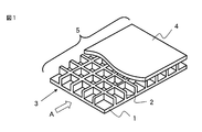
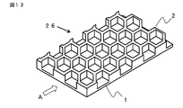
- the model perspective view which shows an example of the molded object (a part of the surface of the second member (II) is omitted) of the present invention Schematic cross-sectional view showing reinforcing fibers that exist across the boundary surface between the surface layer and the core material
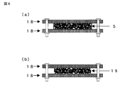
- Schematic diagram showing an example of a burning tool used for measuring the two-dimensional orientation angle of fiber reinforced resin (FIG. 4-a) State before burning (FIG. 4-b) State after burning
- FIG. 4-a) State before burning (FIG. 4-b) State after burning
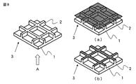
- FIG. 1 is viewed from the A direction) Schematic diagram of an example showing the projected area of a hollow structure
- a schematic perspective view of an example showing the projected area of the surface layer part and the projected area of the core part Schematic diagram of an example showing the shape of the maximum projection surface of a hollow structure
- Schematic diagram of an example showing the shape of the maximum projection surface of a hollow structure Schematic sectional view showing an example of the shape of the core part Schematic diagram and schematic cross section of mold with concave shape
- FIG. 1 Schematic diagram of reinforcing fiber dispersed in fiber bundle
- FIG. 1 A schematic perspective view showing an example of a fiber reinforced resin layer
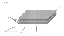
- FIG. 1 Schematic perspective view showing an example of the laminated state of the fiber reinforced resin layer
- FIG. 1 Schematic perspective view for explaining a method for evaluating the number of reinforcing fibers
- the model perspective view which shows an example which cuts out the sample of a surface layer part (a) and a core material part (b) from a molded object
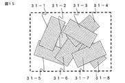
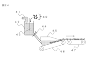
- Schematic diagram showing an example of an apparatus for producing a papermaking substrate 1 is a schematic perspective view of an example showing a laminated configuration of continuous carbon fiber prepregs in Examples.
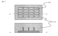
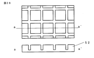
- FIG. Schematic diagram of stamping mold in which the shape of the gap in Example 6 is a quadrangle
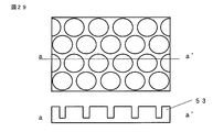
- FIG. Schematic diagram of a stamping mold in which the shape of the gap in Example 7 is circular
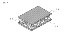
- the schematic diagram which shows the method of obtaining the integrated molded product in Example 12 Schematic perspective view of stacking the surface layer portion and the honeycomb core in Comparative Example 1
- the first member (I) composed of a surface layer portion having a surface shape as shown in FIG. 1 and a core portion having a protrusion shape and the second member (II) are integrated. And a molded body having a hollow structure formed by the core member.
- the first member (I) is made of a fiber reinforced resin (A) composed of a reinforced fiber (a1) and a matrix resin (a2).
- the reinforcing fiber (a1) is particularly preferably a carbon fiber excellent in specific elastic modulus and specific strength because it is required to reduce the weight and rigidity of the molded product.
- fibers such as glass fibers, aramid fibers, boron fibers, PBO fibers, high-strength polyethylene fibers, alumina fibers, and silicon carbide fibers can be used as fiber reinforcement, and two or more of these fibers can be used. You may mix and use.
- these reinforcing fibers may be subjected to surface treatment. Examples of the surface treatment include a metal deposition treatment, a treatment with a coupling agent, a treatment with a sizing agent, and an adhesion treatment of an additive.
- the reinforcing fiber for example, a fiber structure such as a long fiber aligned in one direction, a single tow, a woven fabric, a knitted fabric, a non-woven fabric, a mat, and a braid can be used.
- the unidirectional prepreg is preferable because the fiber direction is uniform and the fiber bending is small, so that the strength utilization rate in the fiber direction is high.
- a woven prepreg is also preferable because a material having low strength and elastic anisotropy can be obtained. It is also possible to form a fiber substrate using a plurality of types of prepregs, for example, both unidirectional prepregs and woven prepregs.
- the “surface layer portion” referred to here is one portion (surface layer portion having a surface shape) constituting the first member (I) 3 shown in FIG.
- the “core material portion” referred to here is two portions (core material portion having a protruding shape) constituting the first member (I) 3 shown in FIG.
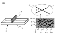
- crossing across refers to a state in which one reinforcing fiber penetrates the boundary surface between the surface layer portion and the core portion as shown in FIG. It may exist in a state of drawing a straight line, a curve or an arc.
- the reinforcing fibers intersect in a complicated manner, and the core material portion can be reinforced more effectively.
- the “boundary surface” is a boundary surface 6 formed by the intersection of the surface layer portion 1 having a surface shape and the core portion 2 having a protruding shape.
- the number of reinforcing fibers present across the surface layer portion and the core material portion are present at 400 / mm 2 or more at the boundary surface between the surface layer portion and the core material portion.
- the number of reinforcing fibers is preferably 700 / mm 2 or more, and more preferably 1000 / mm 2 or more.
- the number of reinforcing fibers is preferably large from the viewpoint of reinforcing the interface between the surface layer portion and the core material portion, but is 10,000 or less per mm 2 from the viewpoints of both rigidity and light weight and moldability. preferable.
- the number of reinforcing fibers is less than 400 fibers / mm 2, the reinforcing effect on the core material portion is lowered, and the core material portion having a protruding shape may be broken from the root by an external force.
- the number average fiber length Ln of the reinforcing fiber (a1) of the present invention is 1 mm or more.
- the fiber length Ln is preferably 2 mm or more, and more preferably 3 mm or more.
- the upper limit of the fiber length Ln is preferably 30 mm or less, more preferably 15 mm or less, because if the fiber length is too long, the moldability may be impaired.
- the reinforcing fibers are discontinuous and monodispersed and randomly dispersed.
- the term “randomly dispersed” as used herein means that the average value of random orientation angles measured by the method described later is in the range of 10 to 80 degrees.
- the random orientation angle is preferably 20 to 70 degrees, more preferably 30 to 60 degrees, and the closer to the ideal angle of 45 degrees, the better. If the average value of the random orientation angle is less than 10 degrees or greater than 80 degrees, it means that many reinforcing fibers are present in a bundle, and not only the mechanical properties are deteriorated but also the isotropic property is impaired. In some cases, the reinforcing fibers in the thickness direction cannot be ignored, and the economic burden in the lamination process may increase.
- FIG. 3 is a schematic diagram showing the dispersion state of the reinforcing fibers when only the reinforcing fibers are observed from the surface direction for an example of the randomly dispersed reinforcing fibers (a1). Focusing on the reinforcing fiber single yarn 10, the reinforcing fiber single yarn 10 intersects with the reinforcing fiber single yarns 11-16. Crossing here means a state where the reinforcing fiber single yarn (1) focused on the observed plane is observed intersecting with other reinforcing fiber single yarn (m).
- the reinforcing fiber 10 and the reinforcing fibers 11 to 16 are not necessarily in contact with each other.
- the random orientation angle is defined as an angle 17 of 0 degree or more and 90 degrees or less, out of two angles formed by two intersecting reinforcing fiber single yarns.
- the method for measuring the average value of the random orientation angle from the fiber reinforced resin include a method of observing the orientation of the reinforced fiber from the surface of the fiber reinforced resin. In this case, polishing the surface of the fiber reinforced resin to expose the fibers is preferable because the reinforcing fibers can be more easily observed.
- the method of illuminating the fiber reinforced resin and observing the orientation of the reinforced fiber using transmitted light can be exemplified. In this case, it is preferable to slice the fiber reinforced resin thinly because it becomes easier to observe the reinforcing fibers.
- a method of photographing a fiber reinforced resin through X-ray CT and taking an orientation image of the reinforced fiber can also be exemplified. In the case of reinforcing fibers with high X-ray permeability, it is easier to observe reinforcing fibers by mixing tracer fibers with reinforcing fibers or applying tracer chemicals to reinforcing fibers. preferable.
- a method of observing the orientation of the reinforcing fibers after removing the resin so as not to destroy the structure of the reinforcing fibers is preferable. For example, as shown in FIG. It is sandwiched between stainless steel meshes and fixed with screws so that the molded body does not move, and then the resin component is burned out or dissolved, and the resulting reinforcing fiber (FIG. 4B) is observed with an optical microscope or an electron microscope. Can be measured.
- the average value of random orientation angles is measured by the following procedures (1) and (2).
- (1) Randomly selected reinforcing fiber single yarn (l) (reinforcing fiber single yarn 10 in FIG. 3) All reinforcing fiber single yarns intersecting (reinforcing fiber single yarns 11 to 16 in FIG. 3) And the average value of the random orientation angles.
- an average value obtained by randomly selecting and measuring 20 reinforcing fiber single yarns may be substituted.
- (2) The measurement of the above (1) is repeated 5 times in total focusing on another reinforcing fiber single yarn, and the average value is calculated as the average value of random orientation angles.
- thermosetting resin selected from the group of thermosetting resins described later, or a thermoplastic resin selected from the group of thermoplastic resins described later can be used.
- the matrix resin (a2) a thermosetting resin as exemplified below can be used, and unsaturated polyester resin, vinyl ester resin, epoxy resin, phenol (resole type) resin, urea melamine Resins, polyimide resins and the like can be preferably used. These copolymers, modified products, and / or resins obtained by blending two or more of these may be used. *
- thermoplastic resins such as polyethylene terephthalate (PET) resin, polybutylene terephthalate (PBT) resin, polytrimethylene terephthalate (PTT).
- PET polyethylene terephthalate
- PBT polybutylene terephthalate
- PTT polytrimethylene terephthalate
- PENp polyethylene naphthalate
- polyester resin such as liquid crystal polyester
- PE polyethylene
- PP polypropylene
- polyolefin resin such as polybutylene resin, styrene resin, urethane resin
- POM Polyoxymethylene
- PA polyamide
- PC polycarbonate
- PMMA polymethyl methacrylate
- PVC polyvinyl chloride
- PPS polyphenylene sulfide
- PPE polyphenyle Ether
- modified PPE resin polyimide (PI) resin, polyamideimide (PAI) resin, polyetherimide (PEI) resin, polysulfone (PSU) resin, modified PSU resin, polyethersulfone (PES) resin, polyketone (PK) resin, polyether ketone (PEK) resin, polyether ether ketone (PEEK) resin, polyether ketone ketone (PEKK) resin, polyether ketone (PEKK) resin, polyether ketone (PEKK) resin,
- PPS resins and PEEK resins are used.
- polycarbonate resins are used.
- polyamides are used.
- a resin or a polyester resin is more preferably used as the matrix resin (a2).
- an impact resistance improver such as an elastomer or a rubber component
- other fillers and additives are added within a range not to impair the purpose of the present invention. Also good. Examples of these include inorganic fillers, flame retardants, conductivity imparting agents, crystal nucleating agents, ultraviolet absorbers, antioxidants, vibration damping agents, antibacterial agents, insect repellents, deodorants, anti-coloring agents, heat stabilizers. , Release agents, antistatic agents, plasticizers, lubricants, colorants, pigments, dyes, foaming agents, antifoaming agents, or coupling agents.
- the homogeneity of the surface layer portion and the core material portion is preferably 70% or more.
- the term “homogeneity” as used herein refers to the ratio of the weight filling rate of reinforcing fibers present in the core portion to the weight filling rate of reinforcing fibers present in the surface layer portion.
- the homogeneity is more preferably 80% or more, and the ideal ratio is 100%, that is, the weight filling amount of reinforcing fibers existing in the surface layer portion and the core material portion is preferably equal.
- the degree of homogeneity is lower than 70%, the reinforcing fiber is not sufficiently filled in the core material portion, and the molded body becomes a weak portion and the rigidity of the molded body decreases.
- the fiber length ratio Lp described later is 30 to 50%, and the fiber reinforcement described later is 10 or more. Is preferred.
- Fiber length ratio refers to the ratio of the length of reinforcing fiber that is shorter than the length spanning each part from the interface between the surface layer part and the core part to the reinforcing fiber of a certain length.
- the fiber length ratio is more preferably 40% or more, and it is preferable that the fiber length ratio is close to 50%.
- the fact that the fiber length ratio is 50% means that the boundary surface of the reinforcing fiber, the surface layer part, and the core part intersects at the center of the reinforcing fiber. This means that the core part can be effectively reinforced.
- the “fiber reinforcement degree” referred to here represents the length of the reinforcing fiber straddling the surface layer portion or the core material portion, and straddles the surface layer portion or the core material portion in the same manner as the fiber length ratio.
- the length of the reinforcing fiber is evaluated for the shorter one.
- Lr ⁇ Lf the following equation (3) is used.
- Lr> Lf the following equation (4) is used.
- the fiber reinforcement degree Fr is more preferably 20 or more and particularly preferably 50 or more from the viewpoint of effective reinforcement.
- the degree of fiber reinforcement is preferably 500 or less from the viewpoint of moldability.
- a value lower than 10 indicates that the length of the reinforcing fiber straddling either the surface layer portion or the core portion is short, and the core portion cannot be effectively reinforced.
- the core portion is not broken by an external force such as bending, so that the rigidity of the entire molded body is increased. Can do.
- the degree of reinforcement of the core member can be evaluated by measuring the shear strength of the core member described later.
- the “hollow structure” referred to in the present invention is formed by the surface layer portion of the first member (I) 3, the protrusion shape 22, the protrusion shape 23, and the surface layer portion of the second member (II) 4 shown in FIG.
- the protrusion shape includes a flat surface, a curved surface, and a wave shape, and a hollow structure is formed by a combination of these protrusion shapes.
- the “maximum projection plane” of the hollow structure referred to in the present invention is a plane having the maximum area among the planes formed when the hollow structure shown in FIG. 7 is projected (refer to Aa in FIG. 7). .
- the “projection plane” as used in the present invention refers to a molded body or a molded body or a view from the direction perpendicular to the surface layer portion of the first member (I) (the viewpoint from the direction of arrow A in FIG. 7). This is the projection plane when the viewpoint of the first member (I) is rotated by 90 degrees and parallel projected (arrow B or arrow C in FIG. 7).
- the plane of the circle that is the projection plane is the maximum, that is, the plane at the position where the diameter is the maximum is the maximum projection plane.
- the plane perpendicular to the direction in which the external force is applied to the molded body is set as the maximum projection plane of the hollow structure.
- the projected area of the core part is preferably 5 to 80% with respect to the projected area of the surface layer part, and more preferably in the range of 20 to 60% from the viewpoint of both rigidity and lightness. It is. If the projected area of the core material portion is lower than 5%, the mechanical properties of the molded body deteriorate, such as the core material portion being easily crushed, and if it exceeds 80%, the void portion is reduced and the lightness is reduced. .
- the “projected area of the surface layer portion” and the “projected area of the core material portion” referred to in the present invention are observed from the direction perpendicular to the surface layer portion. In FIG. 8, the projected area of the surface layer portion is (a).
- the projected area of the core member corresponds to (b).
- the projection area of each part can be obtained by taking the surface of the core part with an image with a scanner or the like and performing binarization processing to obtain the area of the core part, and the width and length of the core part are microscopic. Examples thereof include a method of measuring and calculating using a meter, a caliper, and the like, a method of calculating the area of the core part from the area of the gap formed by the core part.
- the second member (II) in the present invention a member composed of a thermosetting resin or a thermoplastic resin, a member composed of a fiber reinforced resin containing reinforcing fibers, or the like can be used.
- the first member (I) is a member provided with a core part having a protruding shape. By joining and adhering materials having the same shape, a joint surface that becomes a weak portion can be present on the central surface (neutral axis) of the molded body. Further, only the same member may be manufactured, and the cost for manufacturing the member can be reduced.
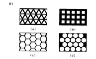
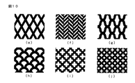
- the shape of the maximum projection surface of the hollow structure formed in the core portion by the protrusion shape in the present invention is a polygon (a triangle in FIG. 9A, a square in (b), and a hexagon in (c). Description), perfect circle shape (described in FIG. 9 (d)), elliptical shape, indefinite shape, over-expanded shape (OX), hanging bell shape (flexible), bisecto, feather, diamond (FIG. 10 (e)), herringbone (Fig. 10 (f)), deformation + shape (Fig. 10 (g)), fan shape (Fig. 10 (h)), + shape (Fig. 10 (i)), shape in which ⁇ and + are combined (Fig. 10 (f).
- the shape is at least one of a circle, an ellipse, a rhombus, a regular triangle, a square, a rectangle, and a regular hexagon.
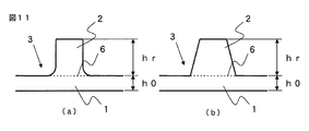
- a taper shape (b) can be illustrated.
- the protrusion shape of the molded body is preferably formed of a fiber reinforced resin composed of a reinforced fiber (a1) and a matrix resin (a2) selected at least from the group described above.
- a molding method such as press molding, injection molding, or RTM molding can be used using a mold having a concave shape as shown in FIG.
- a shape in which the surface layer portion and the core material portion are integrated as shown in FIG. It is preferable from the viewpoint of shortening.
- the height of the protrusion shape of the molded body is preferably 2.0 mm or less, more preferably 1.5 mm or less, and particularly preferably 1.0 mm or less.
- the “projection-shaped height” referred to here is the height hr shown in FIG. 6, and in the first member (I), from the boundary surface (6 in FIG. 5) between the surface layer portion and the core material portion. The distance to the end of the core part (the length of the arrow 2 in FIG. 5).
- the lower limit of the height of the protrusion shape is preferably 0.3 mm or more, more preferably 0.5 mm or more, and particularly preferably 0.8 mm or more, from the viewpoint of weight reduction and high rigidity. Moreover, it is preferable that the height hr (mm) of the core part satisfies the relationship of hr ⁇ 3 ⁇ h0 with respect to the surface layer part thickness h0 (mm) accompanied by the core part.
- Examples of the method for measuring the surface layer thickness h0 of the first member (I) include a method of measuring using an existing measuring means such as a caliper, a micrometer, a laser displacement meter, and a means for measuring the thickness by photographing with a camera. .
- an average value of 10 points randomly measured at intervals of about 100 mm with respect to a face plate portion of a molded product left for 10 minutes in a temperature atmosphere of 23 ° C. using a micrometer. is preferable to make the thickness of the face plate part. Since the higher the height of the core part can enhance the reinforcing effect of the molded body, it is preferable to satisfy the relationship of hr ⁇ 3 ⁇ h0.
- hr is usually 50 times or less of h0.
- the core part which is too tall is difficult to mold, the formability and the reinforcing effect of the surface layer part can be satisfied by providing several core parts having a short height.
- the maximum thickness of the molded product in the present invention is preferably 3.0 mm or less, and more preferably 2.0 mm or less.
- the “maximum thickness” referred to here is the thickness t of the thickest portion of the molded body shown in FIG. 6 and does not include portions where shapes such as uneven portions and protrusions are intentionally attached.
- the specific gravity of the molded body in the present invention is preferably 1.0 or less, more preferably 0.8 or less, from the viewpoint of weight reduction.
- the specific gravity of a molded article having voids as in the present invention is generally an apparent specific gravity (bulk specific gravity), and means a specific gravity including the weight and volume of voids present in the molded body.
- the apparent volume of the molded body is calculated by the method A (underwater substitution method) described in JIS-K 7112, and the apparent specific gravity is calculated.
- a liquid having a specific gravity of less than 1.0 such as ethanol can be used as the immersion liquid.
- the specific gravity is low, the specific gravity is less than 1.0, and measurement is not possible using a liquid such as ethanol, the weight of the molded body is measured using a precision balance and the length of the molded body is measured using a caliper or a micrometer. It is also possible to measure the width, thickness, calculate the volume from the measured values, and use the value obtained by dividing the weight of the obtained molded body by the volume of the molded body as the specific gravity of the molding.
- the integrally molded product of the present invention includes the above-described molded body and the third member (III) joined to the molded body.
- the molded body is, for example, a surface shape
- the third member (III) is formed into a complicated shape having a shape change with respect to the thickness direction.
- the surface shape means that the majority of the projected area is a planar shape or a gentle curved surface shape, as represented by the molded body of FIG.
- the surface shape may form a curved surface portion having a curved surface with a radius of curvature of 1000 m or less, and a plurality of such curved surface portions are intermittently and intermittently provided in one surface of the molded body. May be present.
- a diaphragm having a radius of curvature of 5 mm or more may be formed in these planes.
- the surface shape may be a combination of the plurality of curved surface portions, and the whole may have a three-dimensional form.
- the third member (III) is integrated with the molded body for the purpose of giving a complicated shape to the integrated molded product.
- Complex shapes mean shapes with thickness changes in the vertical, horizontal, and height directions. Structural features, design geometric shapes, and intentionally formed protrusions and dents Including.
- a frame (frame) part, a standing wall part, a hinge part, a boss rib part, etc. represented by the third member (III) in FIG. 14 correspond to this.
- the third member (III) is preferably manufactured by a method that is relatively more mass-productive and more productive than the molded body.
- thermosetting resin selected from the group of thermosetting resins described above, or a thermoplastic resin selected from the group of thermoplastic resins described above, cement, concrete, or Those fiber reinforced products, wood, metal materials, paper materials and the like are preferably used.
- the thermoplastic resin is preferably a fiber reinforced thermoplastic resin, and for the purpose of further enhancing the mechanical properties of the molded product although it is inferior in lightness, a metal material is preferably used.
- a thermoplastic resin composition in which discontinuous reinforcing fibers are dispersed in a thermoplastic resin because both mass productivity, moldability, light weight, and mechanical properties are compatible.
- the blending ratio of the reinforcing fibers in this case is preferably 5 to 75% by weight with respect to the thermoplastic resin composition from the viewpoint of balance between moldability, strength and lightness when the reinforcing fibers are carbon fibers. 15 to 65% by weight is more preferable.
- the integrated molded product of the present invention preferably uses a molded body as a main material. That is, 50% or more of the projected area of the integrally molded product is preferably occupied by the molded body, and more preferably 70% or more of the projected area is occupied by the molded body.
- Examples of the integration method when the integrated molded product of the present invention is manufactured include, for example, an integration method using an adhesive and an integration method using bolts and screws.
- thermal welding, vibration welding, ultrasonic welding, laser welding, insert injection molding, outsert injection molding, or the like is preferably used.
- Outsert molding and insert molding are preferably used from the viewpoint of the molding cycle.
- Examples of the use of the molded body of the present invention and an integrally molded product using the molded body include various gears, various cases, sensors, LED lamps, connectors, sockets, resistors, relay cases, switches, coil bobbins, and capacitors. , Optical pickup, oscillator, various terminal boards, transformer, plug, printed wiring board, tuner, speaker, microphone, headphones, small motor, magnetic head base, power module, semiconductor, display, FDD carriage, chassis, HDD, MO , Motor brush holder, parabolic antenna, notebook computer, mobile phone, digital still camera, PDA, portable MD, parts of electronic equipment such as plasma display, parts and housing, telephone, facsimile, VTR, copier Home or office work represented by TV, iron, hair dryer, rice cooker, microwave oven, audio equipment, vacuum cleaner, toiletries, laser disc (registered trademark), compact disc, lighting, refrigerator, air conditioner, typewriter, word processor, etc.
- the fiber reinforced resin has different fluidity depending on the type, form, arrangement, blending ratio, etc. of the reinforced fiber or resin.
- a fiber-reinforced resin having high fluidity In order to form a core part having a protruding shape such as a rib by molding, it is preferable to use a fiber-reinforced resin having high fluidity, and from the viewpoint of ensuring isotropicity in forming a surface layer part having a surface shape. It is preferable to use a fiber reinforced resin having low fluidity so that a uniform fiber reinforced resin does not flow.
- the fiber reinforced resin is selected according to the part to be flowed and the part not to be flowed, and several examples are given below as criteria for determining the magnitude of the fluidity.
- the sheet-shaped fiber reinforced resin made of the fiber reinforced resin constituting the first member (I) is referred to as a “fiber reinforced resin layer”. Although it does not specifically limit about a sheet-like fiber reinforced resin layer, A preferable form is mentioned later.
- the third is a method of comparing the magnitude of fluidity from the elongation rate of the fiber reinforced resin.
- the “elongation rate” referred to here is obtained by press-molding a disk-shaped fiber reinforced resin layer heated to a melting point or higher and expressing the area ratio of the fiber reinforced resin layer before and after the press as a percentage. As the fiber reinforced resin has a smaller elongation rate, the fluidity becomes poorer.
- the fluidity of the fiber reinforced resin is compared using the fiber interference and the elongation rate.
- concentration parameter p which is an index for determining the magnitude of fiber interference
- the “concentration parameter” of the fiber reinforced resin used in the present invention is an index of the degree of fiber interference, and is a parameter determined by the amount of reinforcing fiber, fiber length, fiber diameter, the number of single fibers constituting the flow unit, etc. And can be expressed by the following equation (5).
- n is the number of flow units composed of reinforcing fibers contained per unit area (1 mm 2 ) of the fiber reinforced resin
- h is the thickness (mm) of the fiber reinforced resin layer
- Ln is the number average fiber of the reinforced fibers. Length (mm).
- the number n of flow units composed of reinforcing fibers contained per unit area (1 mm 2 ) of the fiber reinforced resin is derived from the following equation (6).
- Wf is the basis weight of the reinforcing fiber contained in the fiber reinforced resin (g / m 2 )
- d0 is the diameter of the single fiber ( ⁇ m)
- Ln is the number average fiber length (mm) of the reinforcing fiber
- ⁇ f is the reinforcing fiber.
- k is the average focusing number of flow units.
- the term “flow unit” as used herein refers to one aggregate or simple substance composed of reinforcing fibers. For example, as shown in FIG.
- each parameter used for deriving the concentration parameter is described in detail below.
- each parameter relating to the fiber reinforced resin layer used for derivation of the concentration parameter shown below is calculated on the premise of the fiber reinforced resin layer before heating.
- This premise is that the fiber reinforced resin layer is heated, for example, when the fiber reinforced resin layer to which the foaming agent is added expands and changes in volume, or when the thermoplastic resin melts by heating, the constraint is released. Springback may occur due to elastic recovery of the reinforced fiber, but these are accompanied by volume changes, so even if the mixing ratio of the real reinforced fiber and the thermoplastic resin is the same before and after heating, the obtained concentration parameter This is to eliminate different problems. For this reason, the fiber reinforced resin layer is substantially voidless and is calculated in a state where the resin is completely impregnated.
- the average focusing number k is the number of single fibers constituting the flow unit.
- a flow unit composed of reinforcing fibers is observed, a single fiber is counted one by one, and the number is directly obtained, or a single fiber diameter d0 (shown in advance in FIG. 17).
- a method of obtaining an approximate number of single fibers from the width and height of the flow unit can be exemplified.
- a method of obtaining from the width and height of the flow unit can be preferably used.
- a scanning electron microscope SEM
- an optical microscope for observing a flow unit composed of reinforcing fibers.
- SEM scanning electron microscope
- a scanning electron microscope SEM
- pieces measured at random is employable.
- a method of dissolving using only a fiber reinforced resin solvent (dissolution method), or if there is no solvent to dissolve the resin, only the resin is burned out in a temperature range where the reinforced fiber does not lose its oxidization, and the reinforced fiber
- a method of separating For the reinforcing fibers thus separated, 100 flow units composed of the reinforcing fibers are selected at random, the number of single fibers constituting the flow unit is measured, and the average value is the average focused number k. can do.
- the method of extracting a reinforced fiber from the fiber reinforced resin by a burning method or a dissolution method does not cause a special difference in the obtained result by appropriately selecting the conditions.
- the resin component contained in the fiber reinforced resin is removed by using the above-described method of removing the resin component.
- the method of extracting a reinforced fiber from the fiber reinforced resin by a burning method or a dissolution method does not cause a special difference in the obtained result by appropriately selecting the conditions.
- the basis weight Wf of the reinforcing fiber contained in the fiber reinforced resin can be obtained by removing the resin component contained in the fiber reinforced resin layer and measuring the weight of only the remaining reinforcing fiber.
- a method for removing the resin component contained in the fiber reinforced resin it is preferable to use the method for removing the resin component.
- An electronic scale or an electronic balance can be used for measuring the weight.
- the size of the fiber reinforced resin to be measured is preferably 100 mm ⁇ 100 mm square, the number of measurements is three times, and the average value can be used.
- the density ⁇ f of the reinforcing fiber can be obtained by using an underwater substitution method, a pycnometer method, a floatation method, or the like. Only the resin component can be removed from the 10 mm ⁇ 10 mm square fiber reinforced resin layer by the dissolution method or the burning method, and the remaining reinforcing fiber can be used for measurement. The number of measurements is three, and the average value can be used.
- the thickness h of the fiber reinforced resin layer is the same as the measurement method of the surface layer thickness h0 of the first member (I) described above, such as a caliper, a micrometer, a laser displacement meter, and a means for measuring the thickness by photographing with a camera. Measurement can be performed using existing measuring means. As a method that can be measured easily and accurately, an average value of 10 points randomly measured at intervals of about 100 mm is used for a fiber reinforced resin layer left for 10 minutes in a 23 ° C. temperature atmosphere using a micrometer. The method of setting the thickness of the fiber reinforced resin layer can be specifically exemplified.
- a fiber reinforced resin layer cut out in a disk shape is placed on a mold having a pair of concavity and convex inner surfaces facing each other, and the fiber reinforced resin layer is softened or melted at + 35 ° C. And then press-molded at 20 MPa.
- the elongation rate is defined as the percentage of the area ratio of the fiber reinforced resin layer before and after pressing, as shown in the following formula (8).
- the size of the disk to be cut out is 150 mm in diameter and 2.5 mm in thickness. The measurement is performed three times, and the average is taken as the elongation rate.
- the diameter of the fiber-reinforced resin layer having a disk shape three diameters can be arbitrarily measured and the average value can be used.
- a fiber reinforced resin layer having a concentration parameter p of 2 ⁇ 10 4 or more and 1 ⁇ 10 8 or less is defined as a fiber reinforced resin layer (X), and a fiber reinforced resin mainly forming a surface layer portion.
- the fiber length is short in order to improve the surface appearance in the surface layer portion, and it is preferable that the fiber length is long in order to increase rigidity.
- the concentration parameter p of the fiber reinforced resin layer (X) is more preferably 2 ⁇ 10 4 or more and 1 ⁇ 10 6 or less.
- a fiber reinforced resin layer (Y) having a concentration parameter p of 1 ⁇ 10 1 or more and 0.1 or less of the concentration parameter of the fiber reinforced resin layer (X) is mainly used as a core.
- the fiber reinforced resin forming the material part is used.
- the concentration parameter p of the fiber reinforced resin layer (Y) is preferably 1 ⁇ 10 1 or more and less than 2 ⁇ 10 4.
- the reinforcing effect in the core part can be increased by increasing the fiber length, and is preferably 1 ⁇ 10 2 or more and 0.1 times or less the concentration parameter of the fiber reinforced resin layer (X). .
- the arrangement of the fiber reinforced resin layer (X) and the fiber reinforced resin layer (Y) in the preform used in the present invention is not particularly limited, such as lamination or side-by-side, but the degree of freedom in designing the first member (I). From the viewpoint of enhancing the strength, it is preferable that the preform is formed by laminating the fiber reinforced resin layer (X) and the fiber reinforced resin layer (Y), and more preferably, the fiber reinforced resin layer (X) is a gold having a concave groove. It is a preform formed on the mold surface facing the mold.
- the fiber reinforced resin layer (X) is further arranged on the mold surface side having the concave grooves, and the fiber reinforced resin layer (X) is reinforced with fibers.
- a preform formed by laminating the resin layer (Y) is preferable.
- the fiber reinforced resin layer has a plate thickness of preferably 0.03 to 1.0 mm, and more preferably 0.1 to 0.5 mm, from the viewpoint of design flexibility and simplicity of the preform manufacturing process. Further, an uneven fiber reinforced resin layer as shown in FIG. 18 may be used, and among them, a smooth plate shape is preferable from the viewpoint of workability at the time of lamination.
- the laminated state when the fiber reinforced resin layer is laminated, the laminated state may partially increase or decrease the number of laminated fiber reinforced resin layers as shown in FIG. From the viewpoint of easily forming the core part, it is also preferable to stack a large number of parts on the part to be formed.
- the fiber reinforced resin layer (X) is prevented from flowing in the plane direction, and filling the concave grooves. There is an urging effect.
- the reinforcing fiber (a1) constituting the fiber reinforced resin layer (Y) from the viewpoint of allowing the reinforcing fiber to exist effectively and easily in the core material portion.
- the number average fiber length Lny is preferably 5 times or less, more preferably 3 times or less of the concave groove width b forming the core material portion.
- the fiber reinforced resin layer is disposed at the projection position of the concave groove that forms the core portion having the protrusion shape.
- the reinforced resin layer is disposed substantially in the region of the projection surface of the groove, or the fiber reinforced resin layer is disposed so as to cover the entire region of the projection surface of the groove, or the fiber reinforced resin layer is a groove. It is arranged to be included in a part of the area of the projection plane.
- the fiber reinforced resin layer is disposed so as to cover the entire area of the projection surface of the concave grooves.
- the area of the fiber reinforced resin layer (Y) used in the present invention is 0. 0 of the projected area of the concave grooves forming the core material portion in order to sufficiently fill the core material portion with the fiber reinforced resin layer (Y). 5 times or more is preferable.
- the projected area of the concave groove refers to the area of the projected surface (shaded portion) of the concave groove in the mold.
- the area of the fiber reinforced resin layer (Y) is smaller than this, the amount of fluid flowing to the flat surface portion is larger than filling the core portion, and the filling of the core portion may be insufficient. More preferably, the area of the fiber reinforced resin layer (Y) is preferably 1 or more times the projected area of the groove. When the projected area of the concave groove is small, the size of the fiber reinforced resin layer cut out accordingly is small and the handling becomes worse. Therefore, it is industrial that the area of the fiber reinforced resin layer (Y) is 5 times or more. More preferably, it is 10 times or more.
- the fiber reinforced resin layer (Y) located in the face plate portion may flow, which may disturb the isotropy of the fiber reinforced resin layer (X).
- the core material portion is substantially filled with the fiber reinforced resin layer (Y) disposed in the region of the projection surface of the groove, It is preferably less than 50 times, more preferably less than 30 times.
- the area of the fiber reinforced resin layer (X) is 70% or more of the projected area of the surface layer portion of the first member (I) obtained by molding, and the fiber reinforced resin layer (Y) has a protruding shape. It is preferable to arrange at the projection position of the concave groove formed in the core member having.
- the projected area of the surface layer portion of the first member (I) refers to the area of the projection surface (shaded portion) of the first member (I) in the mold, as shown in FIG.
- the area of the fiber reinforced resin layer (X) is more preferably 80% or more of the projected area of the molded product.
- the upper limit of the area of the fiber reinforced resin layer (X) is preferably 150% or less of the projected area of the molded product from the viewpoint of effectively using the fiber reinforced resin layer and eliminating waste.
- the number average fiber length Lnx of the fiber reinforced resin layer (X) used in the present invention is preferably 2 mm or more in order to ensure the strength of the surface layer portion of the first member (I), more preferably, 3 mm or more.
- the upper limit of the number average fiber length Lnx of the fiber reinforced resin layer (X) is preferably 20 mm or less, and more preferably 10 mm or less, because an excessively long fiber length may impair the formability of the face plate portion. It is.
- the molds used in the present invention are generally roughly classified into two types.
- One is a closed mold used for casting or injection molding, and the other is an open mold used for press molding or forging.
- the hermetically sealed mold is a mold mainly formed by pouring a material into the interior
- the open mold is a mold formed mainly by deforming without flowing the material.
- the closed mold the preform composed of the input fiber reinforced resin layer is blocked from the outside without flowing from inside the cavity, so that the fiber reinforced resin can be effectively and easily recessed into the groove even at low molding pressure.
- the bed can be allowed to flow.
- a fiber-reinforced resin molded body with the ends of the members can be obtained, subsequent secondary processing steps can be reduced and omitted, leading to cost reduction.
- the preform does not flow excessively during molding, the fiber orientation of the fiber reinforced resin layer or preform is disturbed during molding, or the fiber orientation is made anisotropic by flow during molding. It is possible to obtain a molded article that takes advantage of the fiber orientation of the fiber reinforced resin layer or preform. In addition, a molded product with reduced voids can be obtained from the viewpoint of eliminating decomposition gas and mixed air during molding outside the mold.
- the fiber reinforced resin (A) of the first member (I) when the fiber reinforced resin (A) of the first member (I) is formed by laminating a fiber reinforced resin layer, the degree of freedom in design and moldability are improved for the laminated structure of the fiber reinforced resin layer.
- the fiber reinforced resin layer having a small reinforcing fiber volume content Vf and / or a fiber reinforced resin layer composed of a reinforced fiber having a short number average fiber length Ln at a position where a core part having a protruding shape is formed. It is preferable that it is arranged. Since the reinforcing fiber volume content and the number average fiber length of the reinforcing fibers affect the fluidity of the fiber reinforced resin, a material with good fluidity is arranged on the core portion side having a complicated protrusion shape. Thus, the shape can be easily formed. From the same viewpoint, a fiber reinforced resin layer using a low-viscosity matrix resin may be disposed within a range satisfying the characteristics of the molded body.
- ⁇ Evaluation method 1 Evaluation of the number of reinforcing fibers (a1)> A part having a protrusion shape as shown in FIG. 22A is cut out from the obtained molded body, and the surface layer portion having the surface shape as shown in FIG. 22B is the boundary between the surface layer portion and the core material portion.
- the sample was wet-polished to a position where the surface was observable to obtain a sample for cross-sectional observation.
- the entire cross section of the polished sample was photographed at an enlargement magnification of 200 times using an ultra-deep color 3D shape measuring microscope VK-9500 (controller part) / VK-9510 (measuring part) (manufactured by Keyence Corporation).
- VK-9500 controller part
- VK-9510 measuring part
- ⁇ Evaluation method 2 Evaluation of number average fiber length Ln of reinforcing fibers> The molded body was heated in air at 500 ° C. for 1 hour to burn off the resin component. The remaining 400 reinforcing fibers were randomly selected, the length was measured with an optical microscope to the 1 ⁇ m unit, and the number average fiber length was calculated from Equation (7).
- ⁇ Evaluation method 3 Measurement of two-dimensional orientation angle of reinforcing fiber> As shown in FIG. 4, the fiber reinforced resin was sandwiched between two stainless steel meshes (a plain weave shape having 50 meshes per 2.5 cm), and the screws were adjusted and fixed so that the fiber reinforced material did not move. This was heated in air at 500 ° C. for 1 hour to burn off the resin component. Remove the stainless steel mesh, observe the obtained reinforcing fiber substrate with a microscope, select one reinforcing fiber single yarn (l) at random, and another reinforcing fiber single yarn intersecting with the reinforcing fiber single yarn; The two-dimensional orientation angle was measured by image observation.
- orientation angle an angle of 0 ° or more and 90 ° or less (acute angle side) among two angles formed by two reinforcing fiber single yarns intersecting each other was adopted.
- the number of two-dimensional orientation angles measured per selected reinforcing fiber single yarn (l) was 20. The same measurement was performed by selecting a total of five reinforcing fiber single yarns, and the average value was taken as the two-dimensional orientation angle.
- ⁇ Evaluation method 4 Evaluation of homogeneity of surface layer portion and core portion> As shown in FIG. 23 (a), a sample of the core material portion was cut out from the molded body, and the weight Mrc of the core material portion was measured. After the weight measurement, it was heated in air at 500 ° C. for 1 hour to burn off the resin component, and the weight Mrf of the remaining reinforcing fiber was measured. From these weights and the following formula (9), the reinforcing fiber weight filling rate Wfr of the core part was calculated.
- the surface layer part weight Mfc and the weight Mff of the reinforcing fiber after burning were measured.
- the reinforcing fiber weight filling rate Wff was calculated.
- the homogeneity of the surface layer portion and the core material portion was calculated from the values calculated in equations (9) and (10) and the following equation (11).
- the length of the reinforcing fiber existing over the core portion side starting from the boundary surface is Lr
- the length of the reinforcing fiber existing over the surface layer portion side is Lf
- the fiber length ratio Lp of the reinforcing fiber was calculated.
- the number of measured fiber length ratios per sample was 50, and the average of these values was used as the fiber length ratio.
- the fiber reinforcement ratio was calculated from the obtained fiber length ratios Lp, Lr and Lf according to the above-described formula (3) or formula (4).
- composition ratio of the core part was calculated from the following formula (12) from the width and length of the core part.
- the total cross-sectional area of the core part can also be calculated by dividing the area of the void from the cross-sectional area of the surface layer as shown in the following formula (13).
- ⁇ Evaluation Method 7 Evaluation of Specific Gravity of Molded Body>
- the molded body was cut into a size of 20 mm ⁇ 20 mm and used as a sample for evaluating specific gravity. Measurement was performed according to JIS K 7112 A method (underwater substitution method) except that ethanol was used for this sample and the immersion liquid.
- the specific gravity of the molded body was lower than the specific gravity of ethanol, the length, width, and thickness of the cut sample were measured using a micrometer, and the volume of the molded body was calculated. Further, the weight of the cut sample was measured using a precision balance. A value obtained by dividing the weight of the obtained molded body by the volume of the molded body was defined as the specific gravity of the molded body.
- the basis weight and fiber weight fraction of each fiber reinforced resin layer were measured as follows. A square plate of 100 mm ⁇ 100 mm was cut out from the fiber reinforced resin layer, and its weight w0 (g) was measured. Next, the cut fiber reinforced resin layer was heated in air at 500 ° C. for 1 hour, and the weight w1 (g) of the reinforced fiber remaining after burning the resin component was measured.
- the basis weight (g / m 2 ) of the reinforcing fiber contained in the fiber-reinforced resin layer was derived from the weight w1 (g) of the reinforcing fiber.
- the fiber weight fraction (wt%) was calculated
- the average convergence number k of reinforcing fibers was measured by the following method.
- the diameter d0 ( ⁇ m) of the single yarn was measured in advance with a scanning electron microscope (SEM).
- SEM scanning electron microscope
- pieces measured at random was employ
- a 100 mm ⁇ 100 mm square plate is cut out from the fiber reinforced resin layer, the square plate is heated in air at 500 ° C. for 1 hour, the resin components are burned off, and the remaining reinforcing fiber is observed with an optical microscope to strengthen it.
- the number average fiber length Ln of the reinforcing fibers contained in each fiber reinforced resin layer was measured as follows. A part of the fiber reinforced resin layer is cut out, heated in an electric furnace at 500 ° C in air for 30 minutes to thoroughly incinerate and remove the resin to separate the reinforced fibers, and randomly extract 400 or more from the separated reinforced fibers. did. The fiber lengths of these extracted reinforcing fibers are measured using an optical microscope, the lengths of 400 fibers are measured to the 1 ⁇ m unit, and the number average fiber length Ln is calculated using the above-described formula (7). Calculated.
- the number n of flow units composed of reinforcing fibers contained per unit area (1 mm 2 ) of the fiber reinforced resin layer was derived from the above-described equation (6).
- concentration parameter p of the fiber reinforced resin layer was derived from the above-described formula (5).
- the elongation rate of the fiber reinforced resin layer was measured as follows. First, a disk having a diameter of 150 mm was cut out from the fiber reinforced resin layer. A disk-shaped fiber reinforced resin layer with a thickness adjusted to 2.0 mm was used as a measurement sample, placed in an oven equipped with a far infrared heater, and preheated for 10 minutes. At this time, using a multi-input data collection system (manufactured by Keyence Corporation, NR-600), a thermocouple was installed on the surface of the sample and in the center of the disk, and the thermal history was measured.
- a multi-input data collection system manufactured by Keyence Corporation, NR-600
- the sample taken out of the oven was placed on the lower mold, the upper mold was lowered, and press molding was performed at a surface pressure of 20 MPa. After pressurizing and cooling in this state for 1 minute, the upper mold was raised to obtain a molded product.
- the obtained molded product had a substantially circular disk shape.
- the diameter of the molded product was measured at any two locations, and the area of the molded product after molding was derived using the average value.
- the area of the fiber reinforced resin layer before molding was calculated with a diameter of 150 mm.
- the elongation percentage of the fiber reinforced resin layer was determined by the above-described formula (8).
- ⁇ Evaluation Method 10 Evaluation of Shear Strength of Core Material>
- a test piece having a width of 5 mm having one core part as shown in FIG. 22A is cut out from the first member (I), and the width and length of the boundary surface between the surface layer part and the core part are micronized. It measured using a meter and a caliper.
- This test piece was fixed to a shear evaluation jig, a compressive shear load was applied to the core part with reference to JIS K7076, and the load when the core part was broken was measured. A value obtained by dividing this load by the area of the boundary surface was defined and determined as the shear strength of the core part.
- ⁇ Evaluation Method 11 Rigidity Evaluation of Molded Body> A test piece having a width of 25 mm was cut out from the obtained molded body, and the thickness of the test piece was measured using a micrometer. With reference to JIS K7074, this test piece was deformed until a bending load was applied to the test piece under a condition that the ratio L / D of the thickness of the test piece to the span was 12, and the bending deflection became 2 mm or more.
- the evaluation is C when the test piece breaks and / or breakage / peeling of the core part of the test piece occurs until the bending deflection reaches 2 mm, and B shows the case where the bending deflection occurs over 2 mm and 4 mm or less.
- the case where the bending deflection did not occur even when exceeding 4 mm was defined as A.
- Acid-modified polypropylene resin > “Admer” (registered trademark) QE510, melting point 160 ° C., manufactured by Mitsui Chemicals, Inc.
- ⁇ Reference Example 16 Preparation of carbon fiber mat 1> A dispersion having a concentration of 0.1% by weight in which water and a surfactant (manufactured by Nacalai Tex Co., Ltd., polyoxyethylene lauryl ether (trade name)) are mixed is prepared, and this dispersion and the chopped carbon fiber 1 are combined.
- a papermaking substrate was produced using the papermaking substrate production apparatus of FIG.
- the manufacturing apparatus includes a cylindrical container having an opening cock at a lower part of a container as a dispersion tank, and a linear transport unit that connects the dispersion tank and the papermaking tank.
- a stirrer is attached to the opening on the upper surface of the dispersion tank, and chopped carbon fiber and dispersion liquid (dispersion medium) can be input from the opening.
- the papermaking tank includes a mesh conveyor having a papermaking surface at the bottom, and a conveyor capable of transporting a carbon fiber substrate (papermaking substrate) is connected to the mesh conveyor. Papermaking was performed at a carbon fiber concentration of 0.05% by weight in the dispersion. After dehydration by suction, the carbon fiber mat 1 was obtained by drying at 150 ° C. for 2 hours.
- ⁇ Reference Example 26 Preparation of molding material 1>
- the carbon fiber mat 1 obtained in Reference Example 16 and the nylon 6 resin film obtained in Reference Example 22 were laminated to prepare a preform.
- a preform sandwiched between release sheets was placed on a metal tool plate, and a tool plate was placed on the preform.
- a “Teflon” (registered trademark) sheet was used as a release sheet.
- the preform was placed between the hot platen surfaces of a hydraulic press machine composed of upper and lower hot platen surfaces heated to 250 ° C., and pressed at a surface pressure of 5 MPa.
- Example 1 As the fiber reinforced resin layer, two molding materials 9 obtained in Reference Example 34 and one molding material 3 obtained in Reference Example 28 were used. Here, from the concentration parameter p of each fiber reinforced resin layer, the molding material 9 is classified into the fiber reinforced resin layer (X), and the molding material 3 is classified into the fiber reinforced resin layer (Y). These molding materials were laminated so as to be fiber reinforced resin layer (X) / fiber reinforced resin layer (Y) / fiber reinforced resin layer (X) to obtain a preform (1). This preform (1) was preheated to 280 ° C. in a nitrogen atmosphere in a far infrared heating furnace. The cavity surface temperature of the mold is 120 ° C., and the height of the core portion is 1 mm. The hollow structure shown in FIG.
- the preform (1) was placed in a stamping mold, the mold was closed, the mold was pressurized at a molding pressure of 30 MPa, and held for 2 minutes. Thereafter, the mold was opened and removed to obtain a first member (I 1 ) having a honeycomb-shaped core part.
- the preform (1) was well shaped according to the shape of the mold, and the first member (I 1 ) with good shape quality was obtained. Table 3 shows the characteristics of the first member (I 1 ).
- the second member (II) three continuous carbon fiber prepregs of Reference Example 13 and one copolymer nylon resin film obtained in Reference Example 23 were used. As shown in FIG. 25, continuous carbon fiber prepregs were laminated so that the fiber direction was [0 ° / 90 ° / 0 °], and one film was laminated on one side of the 0 ° layer.
- the preform composed of the fiber reinforced resin layer and the film was heated at 150 ° C. for 30 minutes while applying a surface pressure of 0.6 MPa to cure the thermosetting resin. After the curing, the mixture was cooled at room temperature to obtain a second member (II 1 ) having an average thickness of 0.4 mm.
- Example 2 As the fiber reinforced resin layer, two molding materials 8 obtained in Reference Example 33 and one molding material 2 obtained in Reference Example 27 were used. Here, from the concentration parameter p of each fiber reinforced resin layer, the molding material 8 is classified into the fiber reinforced resin layer (X), and the molding material 2 is classified into the fiber reinforced resin layer (Y). In addition, a molded body (2) was obtained using the same as in Example 1 except that the molding pressure was 15 MPa. The characteristics are shown in Table 3.
- Example 3 In the same manner as in Example 1, two first members (I 3 ) were formed, and one first member (I 3 ) was used as the second member (II 3 ). The obtained first member (I 3 ) and second member (II 3 ) are overlapped so that the core parts are in contact with each other as shown in FIG. 27, and the core parts are bonded with an ultrasonic welding machine. As a result, a molded body (3) was obtained. The characteristics are shown in Table 3.
- Example 4 The first member (I 4 ) is set to 2 in the same manner as in Example 1 except that a molding die in which the shape of the gap formed by the core part as shown in FIG. 28 is a square is used. One of the first members (I 4 ) was used as the second member (II 4 ). The obtained first member (I 4 ) and second member (II 4 ) were superposed so that the core parts were in contact with each other in the same manner as in Example 3, and the core part was removed using an ultrasonic welding machine. Bonded to obtain a molded body (4). The characteristics are shown in Table 3.
- Example 5 The first member (I 5 ) is the same as in Example 1 except that a molding die is used in which the shape of the gap formed by the core portion as shown in FIG. 29 is circular.
- the two first members (I 5 ) were used as the second member (II 5 ).
- the obtained first member (I 5 ) and second member (II 5 ) were overlapped so that the core parts were in contact with each other in the same manner as in Example 3, and the core part was removed with an ultrasonic welding machine. Bonded to obtain a molded body (5).
- the characteristics are shown in Table 3.
- a hollow mold has a maximum projection surface of a regular hexagonal shape, and a sealing die having a groove depth of 1.3 mm in the core portion where the cavity and the outside are cut off is used.
- the surface temperature was 260 ° C.
- two molding materials 9 obtained in Reference Example 34 classified as a fiber reinforced resin layer (X) and a molding obtained in Reference Example 29 classified as a fiber reinforced resin layer (Y).
- a preform composed of one piece of material 4 is placed, the mold is closed, preheating is performed for 1 minute in a state where the pressure is 0, and then pressurized at 5 MPa and held for 5 minutes, and then the heater of the press molding machine is turned off.
- first member (I 6 ) having a honeycomb-shaped core member.
- the first member (I 6 ) was well shaped along the shape of the mold, and the first member (I 6 ) with good shape quality was obtained.
- a molded body (6) was obtained in the same manner as in Example 1, except that the obtained first member (I 6 ) was used in place of the first member (I 1 ). The characteristics are shown in Table 3.
- Example 7 As the fiber reinforced resin layer, two molding materials 7 obtained in Reference Example 32 and one molding material 1 obtained in Reference Example 26 were used. Here, from the concentration parameter p of each fiber reinforced resin layer, the molding material 7 is classified into the fiber reinforced resin layer (X), and the molding material 1 is classified into the fiber reinforced resin layer (Y). Except having changed the fiber reinforced resin layer, it carried out similarly to Example 1, and obtained the molded object (7). The characteristics are shown in Table 3.
- Example 8 As the fiber reinforced resin layer, two molding materials 5 obtained in Reference Example 30 and one molding material 11 obtained in Reference Example 36 were used. Here, from the concentration parameter p of each fiber reinforced resin layer, the molding material 5 is classified into the fiber reinforced resin layer (X), and the molding material 11 is classified into the fiber reinforced resin layer (Y). Except having changed the fiber reinforced resin layer, it carried out similarly to Example 1, and obtained the molded object (8). The characteristics are shown in Table 4.
- Example 9 As the fiber reinforced resin layer, two molding materials 7 obtained in Reference Example 32 and one molding material 12 obtained in Reference Example 37 were used. Here, from the concentration parameter p of each fiber reinforced resin layer, the molding material 7 is classified into the fiber reinforced resin layer (X), and the molding material 12 is classified into the fiber reinforced resin layer (Y). Except having changed the fiber reinforced resin layer, it carried out similarly to Example 1, and obtained the molded object (9). The characteristics are shown in Table 4.
- Example 10 As the fiber reinforced resin layer, two molding materials 15 obtained in Reference Example 40 and one molding material 13 obtained in Reference Example 38 were used. Here, from the concentration parameter p of each fiber reinforced resin layer, the molding material 15 is classified into the fiber reinforced resin layer (X), and the molding material 13 is classified into the fiber reinforced resin layer (Y). Other than changing the fiber reinforced resin layer, preheating to 230 ° C. in a nitrogen atmosphere using a far infrared heating furnace, and setting the cavity surface temperature of the mold for molding the first member (I) to 100 ° C. Obtained a molded body (10) in the same manner as in Example 3. The characteristics are shown in Table 4.
- Example 11 As the fiber reinforced resin, two molding materials 14 obtained in Reference Example 39 and one molding material 16 obtained in Reference Example 41 were used. Here, from the concentration parameter p of each fiber reinforced resin layer, the molding material 14 is classified into the fiber reinforced resin layer (X), and the molding material 16 is classified into the fiber reinforced resin layer (Y). Except having changed the fiber reinforced resin layer, it carried out similarly to Example 10, and obtained the molded object (11). The characteristics are shown in Table 4.
- Example 12 As the fiber reinforced resin layer, two molding materials 19 obtained in Reference Example 44 and one molding material 17 obtained in Reference Example 42 were used. Here, from the concentration parameter p of each fiber reinforced resin layer, the molding material 19 is classified into the fiber reinforced resin layer (X), and the molding material 19 is classified into the fiber reinforced resin layer (Y). Other than changing the fiber reinforced resin layer, preheating to 300 ° C. in a nitrogen atmosphere using a far infrared heating furnace, and setting the cavity surface temperature of the mold for molding the first member (I) to 150 ° C. Obtained a molded body (12) in the same manner as in Example 3. The characteristics are shown in Table 4.
- Example 13 As the fiber reinforced resin, two molding materials 18 obtained in Reference Example 43 and one molding material 20 obtained in Reference Example 45 were used. Here, from the concentration parameter p of each fiber reinforced resin layer, the molding material 18 is classified into the fiber reinforced resin layer (X), and the molding material 20 is classified into the fiber reinforced resin layer (Y). Except having changed the fiber reinforced resin layer, it carried out similarly to Example 12, and obtained the molded object (13). The characteristics are shown in Table 4.
- Example 14 The molded body obtained in Example 1 was placed in an injection mold as shown in FIG.
- the third member (III) the long fiber reinforced nylon resin pellet of Reference Example 13 was prepared, and an integrally molded product having a shape as shown in FIG.
- the injection molding was performed using a J350EIII injection molding machine manufactured by Nippon Steel Works, and the cylinder temperature was 260 ° C.
- the obtained integrally molded product has high rigidity and light weight, and mechanically because the third member (III) flows into the gap formed at the end of the molded body. It was a strong joined state.
- Example 1 As the surface layer part, two second members (II 1 ) used in Example 1 were prepared, and as the core part, the nylon 6 resin honeycomb core obtained in Reference Example 46 was used, and as shown in FIG. Lamination was performed such that the resin film side of the surface layer portion was in contact with the honeycomb core of the core material portion, and the laminate was heated at 180 ° C. while applying a surface pressure of 1 MPa with a press molding machine. Then, after taking out from a press molding machine, it cooled at room temperature and obtained the molded object (31) in which the surface layer part and the core material part were integrated. The characteristics are shown in Table 5.
- a molded body (32) was obtained in the same manner as in Comparative Example 1 except that the foamed PP sheet of Reference Example 14 was used as the core part. The characteristics are shown in Table 5.
- Comparative Example 4 A molded body (34) was obtained in the same manner as in Comparative Example 3, except that the long fiber reinforced nylon resin pellets of Reference Example 15 were used. The characteristics are shown in Table 5.
- Example 5 As the fiber reinforced resin layer, the same as Example 1 except that two molding materials 10 obtained in Reference Example 35 classified as the fiber reinforced resin layer (X) are used instead of the molding material 1 and the molding material 2 Thus, a molded body (35) was obtained. The characteristics are shown in Table 5.
Landscapes
- Engineering & Computer Science (AREA)
- Mechanical Engineering (AREA)
- Textile Engineering (AREA)
- Chemical & Material Sciences (AREA)
- Composite Materials (AREA)
- Laminated Bodies (AREA)
- Moulding By Coating Moulds (AREA)
- Manufacturing & Machinery (AREA)
- Materials Engineering (AREA)
- Health & Medical Sciences (AREA)
- Chemical Kinetics & Catalysis (AREA)
- Medicinal Chemistry (AREA)
- Polymers & Plastics (AREA)
- Organic Chemistry (AREA)
- Casting Or Compression Moulding Of Plastics Or The Like (AREA)
- Reinforced Plastic Materials (AREA)
Abstract
Priority Applications (7)
| Application Number | Priority Date | Filing Date | Title |
|---|---|---|---|
| CN201380059142.9A CN104781065B (zh) | 2012-12-26 | 2013-12-11 | 具有中空结构的成型体及其制造方法 |
| US14/440,815 US20150266260A1 (en) | 2012-12-26 | 2013-12-11 | Molded product having hollow structure and process for producing same |
| JP2013556709A JP5578290B1 (ja) | 2012-12-26 | 2013-12-11 | 中空構造を有する成形体およびその製造方法 |
| ES13869192T ES2719499T3 (es) | 2012-12-26 | 2013-12-11 | Producto moldeado que tiene estructura hueca y proceso para producir el mismo |
| KR1020157005437A KR101688868B1 (ko) | 2012-12-26 | 2013-12-11 | 중공 구조를 갖는 성형체 및 그 제조 방법 |
| EP13869192.8A EP2939818B1 (fr) | 2012-12-26 | 2013-12-11 | Corps moulé possédant une structure creuse, et procédé de fabrication de celui-ci |
| CA2889501A CA2889501C (fr) | 2012-12-26 | 2013-12-11 | Corps moule possedant une structure creuse, et procede de fabrication de celui-ci |
Applications Claiming Priority (2)
| Application Number | Priority Date | Filing Date | Title |
|---|---|---|---|
| JP2012-282879 | 2012-12-26 | ||
| JP2012282879 | 2012-12-26 |
Publications (1)
| Publication Number | Publication Date |
|---|---|
| WO2014103711A1 true WO2014103711A1 (fr) | 2014-07-03 |
Family
ID=51020800
Family Applications (1)
| Application Number | Title | Priority Date | Filing Date |
|---|---|---|---|
| PCT/JP2013/083149 Ceased WO2014103711A1 (fr) | 2012-12-26 | 2013-12-11 | Corps moulé possédant une structure creuse, et procédé de fabrication de celui-ci |
Country Status (10)
| Country | Link |
|---|---|
| US (1) | US20150266260A1 (fr) |
| EP (1) | EP2939818B1 (fr) |
| JP (1) | JP5578290B1 (fr) |
| KR (1) | KR101688868B1 (fr) |
| CN (1) | CN104781065B (fr) |
| CA (1) | CA2889501C (fr) |
| ES (1) | ES2719499T3 (fr) |
| PT (1) | PT2939818T (fr) |
| TW (1) | TWI579144B (fr) |
| WO (1) | WO2014103711A1 (fr) |
Cited By (15)
| Publication number | Priority date | Publication date | Assignee | Title |
|---|---|---|---|---|
| TWI573468B (zh) * | 2014-10-02 | 2017-03-01 | Cheng Sheng Chen | A structure for an audio device |
| JP2017080930A (ja) * | 2015-10-23 | 2017-05-18 | 三菱レイヨン株式会社 | 繊維強化樹脂成形品およびその製造方法 |
| US20170334151A1 (en) * | 2016-05-18 | 2017-11-23 | Dell Products L.P. | Apparatus and method for a high performance carbon fiber laminate enclosure part for an information handling system |
| JP2017205885A (ja) * | 2016-05-16 | 2017-11-24 | 石川県 | 繊維強化樹脂製サンドイッチ構造体及び繊維強化樹脂製サンドイッチ構造体の製造方法 |
| CN107614579A (zh) * | 2015-05-22 | 2018-01-19 | 株式会社神户制钢所 | 带状预浸料及纤维强化成形体 |
| EP3590674A4 (fr) * | 2017-03-01 | 2020-01-08 | Nissan Motor Co., Ltd | Corps moulé en résine renforcée de fibres de carbone et procédé de fabrication dudit corps moulé en résine renforcée de fibres de carbone |
| JP2020023647A (ja) * | 2018-08-08 | 2020-02-13 | 株式会社イノアックコーポレーション | 繊維強化樹脂成形体 |
| JPWO2021106650A1 (fr) * | 2019-11-29 | 2021-06-03 | ||
| JPWO2021106649A1 (fr) * | 2019-11-29 | 2021-06-03 | ||
| US20220081058A1 (en) * | 2017-03-31 | 2022-03-17 | TimberWolf Cycles Inc. | High Performance Light Weight Vehicle Frame |
| KR102389987B1 (ko) * | 2020-12-14 | 2022-04-22 | 도레이첨단소재 주식회사 | Cfrtp 허니컴 보강재 및 이의 제조방법 |
| WO2023167335A1 (fr) * | 2022-03-03 | 2023-09-07 | 東レ株式会社 | Matériau de noyau, structure peau-noyau, pale mobile d'aéronef, panneau de plancher d'aéronef, carénage de fusée et partie inter-étage de fusée |
| JP2023143202A (ja) * | 2022-03-25 | 2023-10-06 | フクビ化学工業株式会社 | 繊維強化樹脂成形体及びその製造方法 |
| WO2024171896A1 (fr) * | 2023-02-13 | 2024-08-22 | 三井化学株式会社 | Corps moulé en résine renforcée par des fibres et sa méthode de fabrication |
| WO2025203256A1 (fr) * | 2024-03-26 | 2025-10-02 | 三菱電機株式会社 | Charnière et structure de déploiement |
Families Citing this family (69)
| Publication number | Priority date | Publication date | Assignee | Title |
|---|---|---|---|---|
| EP3120984B1 (fr) | 2014-02-14 | 2023-03-22 | Mitsubishi Chemical Corporation | Plastique renforcé par des fibres et son procédé de production |
| JP6444113B2 (ja) * | 2014-09-25 | 2018-12-26 | 株式会社放電精密加工研究所 | プレス成形システム及びプレス成形方法 |
| KR101683511B1 (ko) * | 2015-03-16 | 2016-12-07 | 현대자동차 주식회사 | 자동차용 범퍼 백 빔 |
| WO2016185743A1 (fr) * | 2015-05-21 | 2016-11-24 | 三菱電機株式会社 | Âme alvéolaire, structure de prise en sandwich alvéolaire, et procédé de production d'âme alvéolaire |
| USD777451S1 (en) * | 2015-06-25 | 2017-01-31 | Avintiv Specialty Materials Inc. | Nonwoven fabric |
| CN104943331B (zh) * | 2015-07-07 | 2017-08-01 | 青岛泰泓轨道装备有限公司 | 一种冲压蜂窝滚压装置及蜂窝成型方法 |
| US10253512B2 (en) * | 2015-09-09 | 2019-04-09 | Walk Safe Innovations, Llc | Rough-in box for creating penetrations in poured concrete flooring and method of use |
| US10571963B2 (en) | 2015-09-18 | 2020-02-25 | Toray Industries, Inc. | Housing |
| FR3043358B1 (fr) * | 2015-11-09 | 2018-04-06 | Airbus Operations | Outillage de formage d'une ebauche en materiau composite et procede de fabrication d'une piece en materiau composite utilisant ledit outillage |
| CN105346150A (zh) * | 2015-12-10 | 2016-02-24 | 黄立群 | 一种具有二次成型结构的空心板及其制作工艺 |
| WO2017110603A1 (fr) * | 2015-12-25 | 2017-06-29 | 東レ株式会社 | Article moulé composite et son procédé de fabrication |
| US20170217056A1 (en) * | 2016-01-29 | 2017-08-03 | Dell Products L.P. | Carbon Fiber Information Handling System Housing and Process for Manufacture |
| EP3348393B1 (fr) * | 2016-04-14 | 2023-06-21 | Sefar AG | Membrane composite et procédé de fabrication d'une membrane composite |
| JP6981405B2 (ja) * | 2016-05-27 | 2021-12-15 | 三菱瓦斯化学株式会社 | 材料および成形品 |
| US20210252352A1 (en) * | 2016-07-01 | 2021-08-19 | Aldila Golf Corporation | Shafts with reinforcing layer for sporting goods and methods of manufacture |
| PL418036A1 (pl) * | 2016-07-21 | 2018-01-29 | Science Effect Spółka Z Ograniczoną Odpowiedzialnością | Element strukturalny do płyt drewnopodobnych, oraz płyta z elementem strukturalnym |
| CA3029565A1 (fr) | 2016-08-18 | 2018-02-22 | Aadg, Inc. | Panneau de porte isole renforce de fibres et son procede de fabrication |
| US10309148B2 (en) | 2016-09-27 | 2019-06-04 | Aadg, Inc. | Polycarbonate honeycomb core door and method of making same |
| US10429152B2 (en) | 2016-09-29 | 2019-10-01 | Aadg, Inc. | Fiber reinforced plastic door with polycarbonate ballistic core and method of making same |
| KR101836712B1 (ko) * | 2016-10-06 | 2018-03-08 | 현대자동차주식회사 | 자동차용 에어백 도어의 힌지 장치 |
| KR101901333B1 (ko) * | 2016-11-21 | 2018-11-05 | 주식회사 라컴텍 | Cfrp 프리프레그를 이용한 성형품의 제조방법 |
| US10392097B2 (en) | 2017-02-16 | 2019-08-27 | The Boeing Company | Efficient sub-structures |
| GB2559807B (en) * | 2017-02-21 | 2019-05-22 | Pembroke Bow Ltd | Helmet |
| US9950594B1 (en) * | 2017-03-09 | 2018-04-24 | Ford Global Technologies, Llc | Impact absorbing system for a vehicle |
| CN107277732B (zh) * | 2017-04-13 | 2020-09-18 | 瑞声科技(新加坡)有限公司 | 碳纤维球顶及其制造方法 |
| US11186059B2 (en) | 2017-04-14 | 2021-11-30 | Mitsubishi Electric Corporation | Honeycomb sandwich structure and method for manufacturing the same |
| DE102017212860B4 (de) * | 2017-07-26 | 2020-07-09 | Premium Aerotec Gmbh | Vorrichtung und Verfahren zur Herstellung eines gekrümmten Faservorformlings aus einem bi- oder multidirektionalen Faserhalbzeug |
| WO2019022245A1 (fr) * | 2017-07-28 | 2019-01-31 | 日産自動車株式会社 | Matériau d'insonorisation |
| JP7053640B2 (ja) * | 2017-09-25 | 2022-04-12 | 株式会社ジェイエスピー | 表皮材付発泡成形体 |
| CN108274681A (zh) * | 2017-12-04 | 2018-07-13 | 程晏莱 | 一种纤维增强复合材料防撞梁 |
| EP3733372B1 (fr) * | 2017-12-26 | 2022-02-23 | Teijin Limited | Procédé pour la production d'un corps moulé par pressage |
| CN110315660B (zh) * | 2018-03-28 | 2022-06-10 | 福美化学工业株式会社 | 准各向同性补强片材、frp成型体和frp成型体的制造方法 |
| US11387163B2 (en) * | 2018-03-30 | 2022-07-12 | Intel Corporation | Scalable debris-free socket loading mechanism |
| US11449111B2 (en) | 2018-03-30 | 2022-09-20 | Intel Corporation | Scalable, high load, low stiffness, and small footprint loading mechanism |
| US11557529B2 (en) | 2018-03-30 | 2023-01-17 | Intel Corporation | Mechanism combining fastener captivation and assembly tilt control for microprocessor thermal solutions |
| WO2019239002A1 (fr) * | 2018-06-12 | 2019-12-19 | Sensapex Oy | Micro- et nano-positionneur commandé par dilatation thermique et son procédé de fabrication |
| US20200031088A1 (en) * | 2018-07-24 | 2020-01-30 | Abc Technologies Inc. | Hollow article with optimized internal structural members |
| WO2020102363A2 (fr) * | 2018-11-13 | 2020-05-22 | Coats & Clark, Inc. | Composant de véhicule basé sur un faisceau de fibres mélangées sélectif ayant un harnais électrique intégré et une électronique intégrée |
| WO2020129976A1 (fr) * | 2018-12-18 | 2020-06-25 | 本田技研工業株式会社 | Article moulé décoratif |
| KR20210108383A (ko) * | 2018-12-25 | 2021-09-02 | 데이진 가부시키가이샤 | 섬유 강화 열가소성 수지 성형체 및 그 제조 방법 |
| US20220126192A1 (en) * | 2019-02-01 | 2022-04-28 | Pda Ecolab, Sas | Sliding board with corrugated mediums |
| US11731392B2 (en) * | 2019-10-01 | 2023-08-22 | Nippon Steel Corporation | Panel structure |
| EP3800036A1 (fr) * | 2019-10-04 | 2021-04-07 | Crompton Technology Group Limited | Composant composite comprenant des moyens pour détecter des endommagements à peine visibles |
| EP3800035A1 (fr) | 2019-10-04 | 2021-04-07 | Crompton Technology Group Limited | Composant composite comprenant des moyens pour détecter des endommagements à peine visibles |
| MX2020011860A (es) | 2019-11-13 | 2021-06-15 | Abc Tech Inc | Panel sandwich compuesto de fibra natural. |
| EP4067416A4 (fr) * | 2019-11-29 | 2023-12-13 | Toray Industries, Inc. | Préimprégné, préforme, matériau composite renforcé par des fibres, et procédé de production dudit préimprégné, de ladite préforme ou dudit matériau composite renforcé par des fibres |
| KR102214997B1 (ko) * | 2019-12-19 | 2021-02-10 | 사단법인 캠틱종합기술원 | 슬라이딩 코어 방식 및 다단 공급된 프리프레그 인서트물을 이용한 중공 성형 구조체의 제조 방법 |
| US11691357B2 (en) * | 2020-02-03 | 2023-07-04 | Rohr, Inc. | Thermoplastic composite panel systems and methods |
| CN111186147B (zh) * | 2020-02-24 | 2021-10-08 | 江苏亨睿碳纤维科技有限公司 | 连续纤维混杂短切纤维制备轻量化汽车零部件的成型方法 |
| CN111396487B (zh) * | 2020-03-27 | 2022-03-15 | 郑州机械研究所有限公司 | 一种高强减振蜂窝芯及其制造方法 |
| TWI730789B (zh) * | 2020-05-29 | 2021-06-11 | 胡佳狀 | 高分子成型模具、熱固性彈性體的製作方法及其熱固性彈性體 |
| CN120038889A (zh) * | 2020-09-21 | 2025-05-27 | 黄英俊 | 形成曲面的中空物体 |
| US20220106046A1 (en) * | 2020-10-06 | 2022-04-07 | Honeywell International Inc. | Pressure containment component for aircraft systems |
| US20220153069A1 (en) * | 2020-11-16 | 2022-05-19 | University Of North Texas | Metamaterial based tire for quiet cars |
| CN112909542B (zh) * | 2021-01-22 | 2022-05-06 | 惠州Tcl移动通信有限公司 | 一种毫米波天线配置组件及移动终端 |
| CN112848375A (zh) * | 2021-02-01 | 2021-05-28 | 中国京冶工程技术有限公司 | 一种纤维增强树脂基复材构件制作方法 |
| CN113560816B (zh) * | 2021-06-28 | 2022-09-23 | 西安航天发动机有限公司 | 一种航天发动机大型框梁构件的制造方法 |
| IT202100024418A1 (it) * | 2021-09-23 | 2023-03-23 | M M Srl A Socio Unico | Procedimento ed impianto per la realizzazione di un pannello grigliato e pannello cosi’ ottenuto |
| CN113817243A (zh) * | 2021-09-28 | 2021-12-21 | 浙江联洋新材料股份有限公司 | 一种高分子硬质泡沫生产用原料浸渍纤维框架及成型工艺 |
| GB2613769A (en) * | 2021-10-19 | 2023-06-21 | Jonathan Ardern Fergus | A surface panel |
| CN118765231A (zh) * | 2022-03-03 | 2024-10-11 | 东丽株式会社 | 芯材、皮-芯结构体、飞机动桨、飞机地板面板、火箭整流罩和火箭级间部 |
| CN114536744A (zh) * | 2022-03-16 | 2022-05-27 | 裴峰 | 一种基于多材料3d打印技术的空间架构复合材料 |
| KR20240060056A (ko) * | 2022-10-28 | 2024-05-08 | 주식회사 엘지화학 | 성형체 |
| CN115972706A (zh) * | 2022-12-27 | 2023-04-18 | 四川玄武岩纤维新材料研究院(创新中心) | 一种复合材料车厢板及其制作方法 |
| CN116538201A (zh) * | 2023-04-23 | 2023-08-04 | 西安嘉盛智造科技有限公司 | 一种聚合物镶嵌的柔性轴承套 |
| JP2025064015A (ja) * | 2023-10-05 | 2025-04-17 | 株式会社八光 | 医療用弾性シート及びそれを用いた医療器具 |
| CL2023003698A1 (es) * | 2023-12-11 | 2024-03-22 | Univ De Magallanes | Equipo y proceso para fabricar núcleos honeycomb a partir de plástico reciclado |
| KR102700537B1 (ko) * | 2024-02-13 | 2024-08-30 | 아이노드 주식회사 | 자동차 반사기 렌즈 금형 및 3d 프린터를 이용한 그 제조방법 |
| CN118664815B (zh) * | 2024-05-31 | 2025-05-09 | 苏州骏创汽车科技股份有限公司 | 一种汽车刹车片基体的制备系统 |
Citations (11)
| Publication number | Priority date | Publication date | Assignee | Title |
|---|---|---|---|---|
| JPS4967962A (fr) | 1972-11-02 | 1974-07-02 | ||
| JPS62208932A (ja) * | 1986-02-27 | 1987-09-14 | Nippon Kokan Kk <Nkk> | 繊維状フイラ−を分散させたプラスチツクシ−ト |
| JPS6387206A (ja) * | 1986-09-30 | 1988-04-18 | Takiron Co Ltd | 凸リブを備えた成形品の製造方法 |
| JPH04201750A (ja) * | 1990-11-30 | 1992-07-22 | Nishikawa Kasei Co Ltd | 自動車の内装品 |
| JPH0639861A (ja) | 1992-07-23 | 1994-02-15 | Nishikawa Kasei Co Ltd | 表皮一体成形品およびその成形方法 |
| JPH11226984A (ja) * | 1998-02-13 | 1999-08-24 | Idemitsu Petrochem Co Ltd | 厚肉部を有する繊維強化樹脂成形品 |
| JP2008230235A (ja) | 2007-02-22 | 2008-10-02 | Toray Ind Inc | サンドイッチ構造体、およびそれを用いた成形体、電子機器筐体 |
| JP2010012770A (ja) * | 2008-06-02 | 2010-01-21 | Panasonic Electric Works Co Ltd | 樹脂成形品及びその製造方法 |
| JP4862913B2 (ja) | 2009-03-31 | 2012-01-25 | 東レ株式会社 | プリプレグおよびプリフォーム |
| WO2012117593A1 (fr) * | 2011-02-28 | 2012-09-07 | 帝人株式会社 | Corps moulé comprenant un matériau composite de renforcement en fibres |
| JP2013176984A (ja) * | 2012-02-07 | 2013-09-09 | Toray Ind Inc | リブ構造を有する成形品の製造方法 |
Family Cites Families (9)
| Publication number | Priority date | Publication date | Assignee | Title |
|---|---|---|---|---|
| US4201750A (en) * | 1978-04-24 | 1980-05-06 | Engelhard Minerals & Chemicals Corporation | Processing of breunnerite to recover magnesium compounds |
| US4330494A (en) * | 1978-09-13 | 1982-05-18 | Sekisui Kagaku Kogyo Kabushiki Kaisha | Reinforced foamed resin structural material and process for manufacturing the same |
| US4937032A (en) * | 1988-05-31 | 1990-06-26 | Phillips Petroleum Company | Method for molding a composite with an integrally molded rib |
| JP2000079649A (ja) * | 1998-06-26 | 2000-03-21 | Toray Ind Inc | Frp構造体およびその製造方法 |
| EP1081305A4 (fr) * | 1999-03-19 | 2005-03-16 | Toray Industries | Materiau de plastique arme pour toitures, son procede de fabrication, et structures et procedes de liaison d'elements dudit materiau |
| JP2006044262A (ja) * | 2004-07-08 | 2006-02-16 | Toray Ind Inc | 中空成形体およびその製造方法 |
| US7264200B2 (en) * | 2004-07-23 | 2007-09-04 | The Boeing Company | System and method for improved rotor tip performance |
| WO2008038429A1 (fr) * | 2006-09-28 | 2008-04-03 | Toray Industries, Inc. | Plastique renforcé par fibres et son procédé de production |
| US8071205B2 (en) * | 2008-07-31 | 2011-12-06 | Toray Industries, Inc. | Prepreg, preform, molded product, and method for manufacturing prepreg |
-
2013
- 2013-12-11 WO PCT/JP2013/083149 patent/WO2014103711A1/fr not_active Ceased
- 2013-12-11 JP JP2013556709A patent/JP5578290B1/ja active Active
- 2013-12-11 KR KR1020157005437A patent/KR101688868B1/ko not_active Expired - Fee Related
- 2013-12-11 CN CN201380059142.9A patent/CN104781065B/zh active Active
- 2013-12-11 US US14/440,815 patent/US20150266260A1/en not_active Abandoned
- 2013-12-11 CA CA2889501A patent/CA2889501C/fr active Active
- 2013-12-11 EP EP13869192.8A patent/EP2939818B1/fr active Active
- 2013-12-11 PT PT13869192T patent/PT2939818T/pt unknown
- 2013-12-11 ES ES13869192T patent/ES2719499T3/es active Active
- 2013-12-20 TW TW102147444A patent/TWI579144B/zh active
Patent Citations (11)
| Publication number | Priority date | Publication date | Assignee | Title |
|---|---|---|---|---|
| JPS4967962A (fr) | 1972-11-02 | 1974-07-02 | ||
| JPS62208932A (ja) * | 1986-02-27 | 1987-09-14 | Nippon Kokan Kk <Nkk> | 繊維状フイラ−を分散させたプラスチツクシ−ト |
| JPS6387206A (ja) * | 1986-09-30 | 1988-04-18 | Takiron Co Ltd | 凸リブを備えた成形品の製造方法 |
| JPH04201750A (ja) * | 1990-11-30 | 1992-07-22 | Nishikawa Kasei Co Ltd | 自動車の内装品 |
| JPH0639861A (ja) | 1992-07-23 | 1994-02-15 | Nishikawa Kasei Co Ltd | 表皮一体成形品およびその成形方法 |
| JPH11226984A (ja) * | 1998-02-13 | 1999-08-24 | Idemitsu Petrochem Co Ltd | 厚肉部を有する繊維強化樹脂成形品 |
| JP2008230235A (ja) | 2007-02-22 | 2008-10-02 | Toray Ind Inc | サンドイッチ構造体、およびそれを用いた成形体、電子機器筐体 |
| JP2010012770A (ja) * | 2008-06-02 | 2010-01-21 | Panasonic Electric Works Co Ltd | 樹脂成形品及びその製造方法 |
| JP4862913B2 (ja) | 2009-03-31 | 2012-01-25 | 東レ株式会社 | プリプレグおよびプリフォーム |
| WO2012117593A1 (fr) * | 2011-02-28 | 2012-09-07 | 帝人株式会社 | Corps moulé comprenant un matériau composite de renforcement en fibres |
| JP2013176984A (ja) * | 2012-02-07 | 2013-09-09 | Toray Ind Inc | リブ構造を有する成形品の製造方法 |
Cited By (30)
| Publication number | Priority date | Publication date | Assignee | Title |
|---|---|---|---|---|
| TWI573468B (zh) * | 2014-10-02 | 2017-03-01 | Cheng Sheng Chen | A structure for an audio device |
| CN107614579A (zh) * | 2015-05-22 | 2018-01-19 | 株式会社神户制钢所 | 带状预浸料及纤维强化成形体 |
| EP3299408A4 (fr) * | 2015-05-22 | 2018-10-31 | Kabushiki Kaisha Kobe Seiko Sho (Kobe Steel, Ltd.) | Préimprégné en forme de ruban et objet moulé renforcé par des fibres |
| CN107614579B (zh) * | 2015-05-22 | 2021-02-19 | 株式会社神户制钢所 | 带状预浸料及纤维强化成形体 |
| JP2017080930A (ja) * | 2015-10-23 | 2017-05-18 | 三菱レイヨン株式会社 | 繊維強化樹脂成形品およびその製造方法 |
| JP2017205885A (ja) * | 2016-05-16 | 2017-11-24 | 石川県 | 繊維強化樹脂製サンドイッチ構造体及び繊維強化樹脂製サンドイッチ構造体の製造方法 |
| US20170334151A1 (en) * | 2016-05-18 | 2017-11-23 | Dell Products L.P. | Apparatus and method for a high performance carbon fiber laminate enclosure part for an information handling system |
| US10668674B2 (en) * | 2016-05-18 | 2020-06-02 | Dell Products L.P. | Apparatus and method for a high performance carbon fiber laminate enclosure part for an information handling system |
| US11230067B2 (en) | 2017-03-01 | 2022-01-25 | Nissan Motor Co., Ltd. | Carbon fiber-reinforced resin molded body and manufacturing method thereof |
| EP3590674A4 (fr) * | 2017-03-01 | 2020-01-08 | Nissan Motor Co., Ltd | Corps moulé en résine renforcée de fibres de carbone et procédé de fabrication dudit corps moulé en résine renforcée de fibres de carbone |
| US20220081058A1 (en) * | 2017-03-31 | 2022-03-17 | TimberWolf Cycles Inc. | High Performance Light Weight Vehicle Frame |
| JP2020023647A (ja) * | 2018-08-08 | 2020-02-13 | 株式会社イノアックコーポレーション | 繊維強化樹脂成形体 |
| JP7146519B2 (ja) | 2018-08-08 | 2022-10-04 | 株式会社イノアックコーポレーション | 繊維強化樹脂成形体及び繊維強化樹脂成形体の製造方法 |
| JPWO2021106650A1 (fr) * | 2019-11-29 | 2021-06-03 | ||
| JPWO2021106649A1 (fr) * | 2019-11-29 | 2021-06-03 | ||
| US12076943B2 (en) | 2019-11-29 | 2024-09-03 | Toray Industries, Inc. | Fiber-reinforced composite material and sandwich structure |
| CN114761213A (zh) * | 2019-11-29 | 2022-07-15 | 东丽株式会社 | 纤维增强复合材料及夹层结构体 |
| WO2021106650A1 (fr) * | 2019-11-29 | 2021-06-03 | 東レ株式会社 | Matériau composite renforcé par des fibres et structure sandwich |
| WO2021106649A1 (fr) * | 2019-11-29 | 2021-06-03 | 東レ株式会社 | Matériau composite renforcé par des fibres et structure sandwich |
| EP4067033A4 (fr) * | 2019-11-29 | 2023-12-20 | Toray Industries, Inc. | Matériau composite renforcé par des fibres et structure sandwich |
| EP4067034A4 (fr) * | 2019-11-29 | 2023-12-27 | Toray Industries, Inc. | Matériau composite renforcé par des fibres et structure sandwich |
| US12030291B2 (en) | 2019-11-29 | 2024-07-09 | Toray Industries, Inc. | Fiber-reinforced composite material and sandwich structure |
| JP7548017B2 (ja) | 2019-11-29 | 2024-09-10 | 東レ株式会社 | 繊維強化複合材料およびサンドイッチ構造体 |
| JP7543913B2 (ja) | 2019-11-29 | 2024-09-03 | 東レ株式会社 | 繊維強化複合材料およびサンドイッチ構造体 |
| KR102389987B1 (ko) * | 2020-12-14 | 2022-04-22 | 도레이첨단소재 주식회사 | Cfrtp 허니컴 보강재 및 이의 제조방법 |
| WO2023167335A1 (fr) * | 2022-03-03 | 2023-09-07 | 東レ株式会社 | Matériau de noyau, structure peau-noyau, pale mobile d'aéronef, panneau de plancher d'aéronef, carénage de fusée et partie inter-étage de fusée |
| JP2023143202A (ja) * | 2022-03-25 | 2023-10-06 | フクビ化学工業株式会社 | 繊維強化樹脂成形体及びその製造方法 |
| JP7689505B2 (ja) | 2022-03-25 | 2025-06-06 | フクビ化学工業株式会社 | 繊維強化樹脂成形体及びその製造方法 |
| WO2024171896A1 (fr) * | 2023-02-13 | 2024-08-22 | 三井化学株式会社 | Corps moulé en résine renforcée par des fibres et sa méthode de fabrication |
| WO2025203256A1 (fr) * | 2024-03-26 | 2025-10-02 | 三菱電機株式会社 | Charnière et structure de déploiement |
Also Published As
| Publication number | Publication date |
|---|---|
| EP2939818B1 (fr) | 2019-03-13 |
| KR101688868B1 (ko) | 2016-12-22 |
| ES2719499T3 (es) | 2019-07-10 |
| CN104781065A (zh) | 2015-07-15 |
| US20150266260A1 (en) | 2015-09-24 |
| KR20150100608A (ko) | 2015-09-02 |
| PT2939818T (pt) | 2019-05-08 |
| EP2939818A4 (fr) | 2016-06-08 |
| TWI579144B (zh) | 2017-04-21 |
| CA2889501A1 (fr) | 2014-07-03 |
| TW201433459A (zh) | 2014-09-01 |
| CN104781065B (zh) | 2017-03-29 |
| EP2939818A1 (fr) | 2015-11-04 |
| JPWO2014103711A1 (ja) | 2017-01-12 |
| JP5578290B1 (ja) | 2014-08-27 |
| CA2889501C (fr) | 2017-05-23 |
Similar Documents
| Publication | Publication Date | Title |
|---|---|---|
| JP5578290B1 (ja) | 中空構造を有する成形体およびその製造方法 | |
| EP2527139B1 (fr) | Structure sandwich et article formé intégré l'utilisant | |
| JP4862913B2 (ja) | プリプレグおよびプリフォーム | |
| CN108431099B (zh) | 结构体 | |
| JP6822147B2 (ja) | 構造体 | |
| JP4807477B2 (ja) | プレス成形品の製造方法 | |
| US10882224B2 (en) | Method for manufacturing structure material | |
| JP2008230235A (ja) | サンドイッチ構造体、およびそれを用いた成形体、電子機器筐体 | |
| JP5994427B2 (ja) | プレス成形用中間基材、プリフォーム、および成形品の製造方法 | |
| JPWO2019189384A1 (ja) | 成形品の製造方法 | |
| JP5994737B2 (ja) | プレス成形用中間基材、プリフォーム、および成形品の製造方法 | |
| WO2018117180A1 (fr) | Structure et son procédé de fabrication | |
| JP6225497B2 (ja) | プレス成形用中間基材、プリフォーム、および成形品の製造方法 |
Legal Events
| Date | Code | Title | Description |
|---|---|---|---|
| ENP | Entry into the national phase |
Ref document number: 2013556709 Country of ref document: JP Kind code of ref document: A |
|
| 121 | Ep: the epo has been informed by wipo that ep was designated in this application |
Ref document number: 13869192 Country of ref document: EP Kind code of ref document: A1 |
|
| ENP | Entry into the national phase |
Ref document number: 20157005437 Country of ref document: KR Kind code of ref document: A |
|
| ENP | Entry into the national phase |
Ref document number: 2889501 Country of ref document: CA |
|
| WWE | Wipo information: entry into national phase |
Ref document number: 14440815 Country of ref document: US |
|
| WWE | Wipo information: entry into national phase |
Ref document number: 2013869192 Country of ref document: EP |
|
| NENP | Non-entry into the national phase |
Ref country code: DE |