WO2014103744A1 - Analyseur automatique - Google Patents
Analyseur automatique Download PDFInfo
- Publication number
- WO2014103744A1 WO2014103744A1 PCT/JP2013/083407 JP2013083407W WO2014103744A1 WO 2014103744 A1 WO2014103744 A1 WO 2014103744A1 JP 2013083407 W JP2013083407 W JP 2013083407W WO 2014103744 A1 WO2014103744 A1 WO 2014103744A1
- Authority
- WO
- WIPO (PCT)
- Prior art keywords
- reagent
- temperature
- reaction
- automatic analyzer
- reagent dispensing
- Prior art date
- Legal status (The legal status is an assumption and is not a legal conclusion. Google has not performed a legal analysis and makes no representation as to the accuracy of the status listed.)
- Ceased
Links
Images




Classifications
-
- G—PHYSICS
- G01—MEASURING; TESTING
- G01N—INVESTIGATING OR ANALYSING MATERIALS BY DETERMINING THEIR CHEMICAL OR PHYSICAL PROPERTIES
- G01N33/00—Investigating or analysing materials by specific methods not covered by groups G01N1/00 - G01N31/00
- G01N33/48—Biological material, e.g. blood, urine; Haemocytometers
- G01N33/483—Physical analysis of biological material
- G01N33/487—Physical analysis of biological material of liquid biological material
- G01N33/49—Blood
- G01N33/4905—Determining clotting time of blood
-
- G—PHYSICS
- G01—MEASURING; TESTING
- G01N—INVESTIGATING OR ANALYSING MATERIALS BY DETERMINING THEIR CHEMICAL OR PHYSICAL PROPERTIES
- G01N33/00—Investigating or analysing materials by specific methods not covered by groups G01N1/00 - G01N31/00
- G01N33/48—Biological material, e.g. blood, urine; Haemocytometers
- G01N33/50—Chemical analysis of biological material, e.g. blood, urine; Testing involving biospecific ligand binding methods; Immunological testing
- G01N33/86—Chemical analysis of biological material, e.g. blood, urine; Testing involving biospecific ligand binding methods; Immunological testing involving blood coagulating time or factors, or their receptors
-
- G—PHYSICS
- G01—MEASURING; TESTING
- G01N—INVESTIGATING OR ANALYSING MATERIALS BY DETERMINING THEIR CHEMICAL OR PHYSICAL PROPERTIES
- G01N35/00—Automatic analysis not limited to methods or materials provided for in any single one of groups G01N1/00 - G01N33/00; Handling materials therefor
- G01N35/00584—Control arrangements for automatic analysers
- G01N35/00594—Quality control, including calibration or testing of components of the analyser
- G01N35/00613—Quality control
- G01N35/00663—Quality control of consumables
-
- G—PHYSICS
- G01—MEASURING; TESTING
- G01N—INVESTIGATING OR ANALYSING MATERIALS BY DETERMINING THEIR CHEMICAL OR PHYSICAL PROPERTIES
- G01N35/00—Automatic analysis not limited to methods or materials provided for in any single one of groups G01N1/00 - G01N33/00; Handling materials therefor
- G01N35/02—Automatic analysis not limited to methods or materials provided for in any single one of groups G01N1/00 - G01N33/00; Handling materials therefor using a plurality of sample containers moved by a conveyor system past one or more treatment or analysis stations
- G01N35/025—Automatic analysis not limited to methods or materials provided for in any single one of groups G01N1/00 - G01N33/00; Handling materials therefor using a plurality of sample containers moved by a conveyor system past one or more treatment or analysis stations having a carousel or turntable for reaction cells or cuvettes
-
- G—PHYSICS
- G01—MEASURING; TESTING
- G01N—INVESTIGATING OR ANALYSING MATERIALS BY DETERMINING THEIR CHEMICAL OR PHYSICAL PROPERTIES
- G01N35/00—Automatic analysis not limited to methods or materials provided for in any single one of groups G01N1/00 - G01N33/00; Handling materials therefor
- G01N35/10—Devices for transferring samples or any liquids to, in, or from, the analysis apparatus, e.g. suction devices, injection devices
- G01N35/1002—Reagent dispensers
-
- G—PHYSICS
- G01—MEASURING; TESTING
- G01N—INVESTIGATING OR ANALYSING MATERIALS BY DETERMINING THEIR CHEMICAL OR PHYSICAL PROPERTIES
- G01N35/00—Automatic analysis not limited to methods or materials provided for in any single one of groups G01N1/00 - G01N33/00; Handling materials therefor
- G01N35/10—Devices for transferring samples or any liquids to, in, or from, the analysis apparatus, e.g. suction devices, injection devices
- G01N35/1009—Characterised by arrangements for controlling the aspiration or dispense of liquids
- G01N35/1016—Control of the volume dispensed or introduced
-
- G—PHYSICS
- G01—MEASURING; TESTING
- G01N—INVESTIGATING OR ANALYSING MATERIALS BY DETERMINING THEIR CHEMICAL OR PHYSICAL PROPERTIES
- G01N35/00—Automatic analysis not limited to methods or materials provided for in any single one of groups G01N1/00 - G01N33/00; Handling materials therefor
- G01N2035/00346—Heating or cooling arrangements
-
- G—PHYSICS
- G01—MEASURING; TESTING
- G01N—INVESTIGATING OR ANALYSING MATERIALS BY DETERMINING THEIR CHEMICAL OR PHYSICAL PROPERTIES
- G01N35/00—Automatic analysis not limited to methods or materials provided for in any single one of groups G01N1/00 - G01N33/00; Handling materials therefor
- G01N2035/00346—Heating or cooling arrangements
- G01N2035/00356—Holding samples at elevated temperature (incubation)
- G01N2035/00376—Conductive heating, e.g. heated plates
-
- G—PHYSICS
- G01—MEASURING; TESTING
- G01N—INVESTIGATING OR ANALYSING MATERIALS BY DETERMINING THEIR CHEMICAL OR PHYSICAL PROPERTIES
- G01N35/00—Automatic analysis not limited to methods or materials provided for in any single one of groups G01N1/00 - G01N33/00; Handling materials therefor
- G01N2035/00346—Heating or cooling arrangements
- G01N2035/00356—Holding samples at elevated temperature (incubation)
- G01N2035/00386—Holding samples at elevated temperature (incubation) using fluid heat transfer medium
-
- G—PHYSICS
- G01—MEASURING; TESTING
- G01N—INVESTIGATING OR ANALYSING MATERIALS BY DETERMINING THEIR CHEMICAL OR PHYSICAL PROPERTIES
- G01N35/00—Automatic analysis not limited to methods or materials provided for in any single one of groups G01N1/00 - G01N33/00; Handling materials therefor
- G01N2035/00346—Heating or cooling arrangements
- G01N2035/00425—Heating or cooling means associated with pipettes or the like, e.g. for supplying sample/reagent at given temperature
-
- G—PHYSICS
- G01—MEASURING; TESTING
- G01N—INVESTIGATING OR ANALYSING MATERIALS BY DETERMINING THEIR CHEMICAL OR PHYSICAL PROPERTIES
- G01N35/00—Automatic analysis not limited to methods or materials provided for in any single one of groups G01N1/00 - G01N33/00; Handling materials therefor
- G01N2035/00346—Heating or cooling arrangements
- G01N2035/00435—Refrigerated reagent storage
-
- G—PHYSICS
- G01—MEASURING; TESTING
- G01N—INVESTIGATING OR ANALYSING MATERIALS BY DETERMINING THEIR CHEMICAL OR PHYSICAL PROPERTIES
- G01N35/00—Automatic analysis not limited to methods or materials provided for in any single one of groups G01N1/00 - G01N33/00; Handling materials therefor
- G01N35/00584—Control arrangements for automatic analysers
- G01N35/00594—Quality control, including calibration or testing of components of the analyser
- G01N35/00613—Quality control
- G01N35/00663—Quality control of consumables
- G01N2035/00673—Quality control of consumables of reagents
-
- G—PHYSICS
- G01—MEASURING; TESTING
- G01N—INVESTIGATING OR ANALYSING MATERIALS BY DETERMINING THEIR CHEMICAL OR PHYSICAL PROPERTIES
- G01N35/00—Automatic analysis not limited to methods or materials provided for in any single one of groups G01N1/00 - G01N33/00; Handling materials therefor
- G01N35/10—Devices for transferring samples or any liquids to, in, or from, the analysis apparatus, e.g. suction devices, injection devices
- G01N2035/1027—General features of the devices
- G01N2035/1048—General features of the devices using the transfer device for another function
Definitions
- the present invention relates to an automatic analyzer that analyzes the amount of components contained in a sample such as blood or urine, and more particularly to an automatic analyzer that can measure blood coagulation time items and coagulation / fibrinolytic marker items.
- Such blood coagulation includes extrinsic ones in which blood leaked out of the blood vessel is coagulated and intrinsic ones in which blood is coagulated in the blood vessel, and the measurement items regarding the blood coagulation ability (coagulation time)
- the prothrombin time (PT) of the extrinsic blood coagulation reaction test, the activated partial thromboplastin time (APTT) of the intrinsic blood coagulation reaction test, the fibrinogen level (Fbg), etc. are known.
- All of these items are based on optical, physical and electrical detection of fibrin deposited by the addition of a reagent that initiates coagulation.
- the reaction solution is irradiated with light, and the fibrin deposited in the reaction solution is captured the time-dependent intensity change of the scattered light or the transmitted light, and the time when the fibrin starts to precipitate is determined. Methods for calculating are known.
- coagulation factor measurement and coagulation / fibrinolytic marker measurement are also included in addition to blood coagulation time measurement.
- Coagulation factor measurement is mainly performed by the blood coagulation time measurement part, but as for the coagulation / fibrinolytic marker, analysis by a spectrophotometer such as synthetic substrate method, latex agglutination method is performed.
- the measurement result of the coagulation time is required to be reported in units of 0.1 seconds, and it is necessary to continuously measure light, and if the reaction liquid is coagulated Since recycling of the reaction vessel by washing is not possible, the reaction is performed at a separate photometric port and the reaction vessel is disposable.
- the coagulation time is as short as a few seconds, it is necessary to reach 37 ° C., which is the temperature condition required for the reaction, immediately after mixing the sample and the reagent.
- the reagent is usually stored in a reagent storage box at 5 to 10 ° C., and the coagulation time item is used to raise the temperature of the reagent.
- the reagent dispensing mechanism for the reagent is provided with a temperature rising function of the reagent.
- Patent documents 2 and 3 disclose techniques for monitoring the outside air temperature and changing the conditions for raising the temperature of the reagent. However, if the supplied water temperature is unstable even if only the outside air temperature is monitored, there is a problem that the discharge temperature becomes unstable or it takes time to stabilize the temperature of the heating portion.
- the technology of controlling the temperature of the device supply water in the device of Patent Document 5 to improve the dispensing accuracy is introduced, but relates to the temperature control performance of the reagent dispensing mechanism with the reagent temperature raising function It is not a technique to suppress the variation in the temperature fluctuation of the reagent heating part.
- An object of the present invention is to provide an automatic analyzer capable of highly reproducible analysis by realizing stable reagent temperature rise and high dispensing accuracy regardless of the outside air temperature of the apparatus and the fluctuation of the apparatus water temperature. It is.
- the automatic analyzer arranges reaction cells for mixing and reacting a sample and a reagent on the circumference and repeats rotation stop, and a reagent disc and reaction in the reaction cell.
- a constant temperature bath for controlling the solution to a constant temperature
- a first reagent dispensing mechanism for dispensing the reagent into the reaction cell, and light is applied to the reaction solution in the reaction cell to transmit transmitted light or scattered light.
- a second reagent dispensing with a reagent temperature-raising function which dispenses a reagent into a disposable reaction container, and a reaction container supply unit that supplies a disposable reaction container for mixing and reacting a sample and a reagent, and a photometer to be detected
- a coagulation time detection unit for irradiating the reaction liquid in the disposable reaction container with light to detect transmitted light or scattered light, and the coagulation time detection unit and the reagent or reaction in the disposable reaction container
- Temperature control block for controlling the temperature to a constant temperature, a reagent dispensing syringe connected to the second reagent dispensing mechanism with the temperature raising function, and controlling the temperature of the internal fluid of the reagent dispensing syringe And a fluid temperature control mechanism.
- an automatic analyzer capable of highly reproducible analysis by realizing stable reagent temperature rise and high dispensing accuracy regardless of the outside air temperature of the apparatus and the fluctuation of the apparatus water temperature.
- FIG. 1 is a schematic view of an automatic analyzer including a turntable-type biochemical analysis unit and a coagulation time measurement unit according to an embodiment of the present invention. It is the figure which showed the coagulation
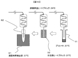
- FIG. 7 is a view showing a reagent dispensing mechanism including a block for making the temperature around the reagent probe constant at the time of discharging the reagent in the embodiment of the present invention.
- FIG. 14 is a diagram showing an example of the operation of the reagent dispensing mechanism including a block for making the temperature around the reagent probe constant at the time of reagent discharge in the embodiment of the present invention.
- FIG. 1 is a system block diagram showing the entire configuration of a turntable-type automatic analyzer as a base of one embodiment of the present invention.
- the automatic analyzer 1 mainly comprises a reaction disc 10, a sample disc 20, a first reagent disc 30a, a second reagent disc 30b, a light source 40, a photometer 41, and a computer 50. There is.
- the reaction disk 10 is provided so as to be capable of intermittent rotation, and a large number of reaction cells 11 made of a translucent material are mounted on the disk along the circumferential direction.
- the reaction cell 11 is maintained at a predetermined temperature (for example, 37 ° C.) by the thermostat 12.
- the fluid in the thermostatic chamber 12 is temperature-controlled by the thermostatic maintenance device 13.
- the thermostatic chamber 12 can control the reagent and the reaction liquid in the reaction cell 11 to a constant temperature.
- sample containers 21 containing biological samples such as blood and urine are mounted on the sample disc 20 along the circumferential direction in a double manner in the illustrated example. Further, in the vicinity of the sample disk 20, a sample dispensing mechanism 22 is disposed.
- the sample dispensing mechanism 22 mainly includes a movable arm 23 and a pipette nozzle 24 attached thereto. With this configuration, at the time of sample dispensing, the sample dispensing mechanism 22 appropriately moves the pipette nozzle 24 to the dispensing position by the movable arm 23, and a predetermined amount of sample is transferred from the sample container 21 positioned at the suction position of the sample disc 20. The sample is sucked and discharged into the reaction cell 11 at the discharge position on the reaction disk 10.
- the first reagent disc 30a and the second reagent disc 30b are respectively disposed inside the first reagent storage 31a and the second reagent storage 31b.
- a plurality of first reagent bottles 32a and second reagent bottles 32b on which a label indicating reagent identification information is displayed like a bar code are attached to the first reagent cooler 31a and the second reagent cooler 31b. It mounts along the circumferential direction of the reagent disc 30a and the 2nd reagent disc 30b, respectively.
- the first reagent bottle 32 a and the second reagent bottle 32 b contain reagent solutions corresponding to analysis items that can be analyzed by the automatic analyzer 1.
- first reagent cooler 31a and the second reagent cooler 31b are provided with the first barcode reader 33a and the second barcode reader 33b, and these devices are used for the first reagent bottle 32a when the reagent is registered. , And read the barcode displayed on the outer wall of the second reagent bottle 32b. The read reagent information is registered in the memory 56 together with the positions on the first reagent disc 30a and the second reagent disc 30b.
- a first reagent dispensing mechanism 34a and a third reagent dispensing mechanism 34b which are substantially the same as the sample dispensing mechanism 22 are disposed, respectively.
- the pipette nozzles provided for these s uck in reagents from the first reagent bottle 32a and the second reagent bottle 32b according to the inspection item positioned at the reagent receiving position on the reaction disc 10, and the corresponding reaction cell 11 Discharge inwards.
- the first stirring mechanism 35a and the second stirring mechanism 35b are located at positions surrounded by the reaction disk 10, the first reagent disk 30a, the second reagent disk 30b, the first reagent dispensing mechanism 34a, and the third reagent dispensing mechanism 34b. It is arranged.
- the mixed solution of the sample and the reagent stored in the reaction cell 11 is stirred by the first stirring mechanism 35a and the second stirring mechanism 35b to accelerate the reaction.
- the light source 40 is disposed near the central portion of the reaction disk 10, and the photometer 41 is disposed on the outer peripheral side of the reaction disk 10.
- the row of reaction cells 11 after stirring is sandwiched by the light source 40 and the photometer 41. Move so as to pass the specified photometric position.
- the light source 40 and the photometer 41 constitute a light detection system.
- the photometer 41 is a photometer that detects transmitted light or scattered light.
- reaction solution of the sample and the reagent in each reaction cell 11 is measured every time it crosses in front of the photometer 41 while the reaction disk 10 is rotating.
- An analog signal of scattered light measured for each sample is input to an A / D (analog / digital) converter 54.
- the used reaction cell 11 is internally cleaned by the reaction cell cleaning mechanism 36 disposed in the vicinity of the reaction disk 10 to allow repeated use.
- the computer 50 is connected to the sample dispensing control unit 52, the reagent dispensing control unit 53, and the A / D converter 54 via the interface 51.
- the computer 50 sends a command to the sample dispensing control unit 52 to control the sample dispensing operation.
- the computer 50 also sends a command to the reagent dispensing control unit 53 to control the dispensing operation of the reagent.
- the photometric values converted into digital signals by the A / D converter 54 are taken into the computer 50.
- a printer 55 for printing Connected to the interface 51 are a printer 55 for printing, a memory 56 which is a storage device, an external output medium 57, a keyboard 58 for inputting operation commands, etc., and a CRT display (display device) 59 for displaying a screen.
- a display device 59 As the display device 59, a liquid crystal display or the like can be adopted in addition to the CRT display.
- the memory 56 is configured of, for example, a hard disk memory or an external memory.
- the memory 56 stores information such as the password of each operator, the display level of each screen, analysis parameters, analysis item request contents, calibration results, analysis results, and the like.
- Analysis parameters related to items that can be analyzed by the automatic analyzer 1 are input in advance via an information input device such as a keyboard 58 and stored in the memory 56. The operator selects the inspection item requested for each sample using the operation function screen.
- the pipette nozzle 24 of the sample dispensing mechanism 22 dispenses a predetermined amount of sample from the sample container 21 to the reaction cell 11 according to the analysis parameter.
- the reaction cell 11 into which the sample is dispensed is transferred by the rotation of the reaction disk 10 and stops at the reagent receiving position.
- the pipette nozzles of the first reagent dispensing mechanism 34a and the third reagent dispensing mechanism 34b dispense a predetermined amount of reagent solution to the reaction cell 11 according to the analysis parameters of the corresponding inspection item.
- the dispensing order of the sample and the reagent may be prior to the sample prior to the sample, contrary to this example.
- the sample and the reagent are stirred and mixed by the first stirring mechanism 35a and the second stirring mechanism 35b.
- the photometer 41 measures the transmitted light or the scattered light of the reaction solution.
- the measured transmitted light or scattered light is converted into a value proportional to the light amount by the A / D converter 54, and is taken into the computer 50 via the interface 51.
- Concentration data is calculated based on a calibration curve measured in advance by an analysis method designated for each inspection item, using the converted numerical values. Component concentration data as an analysis result of each inspection item is output to the screen of the printer 55 or the CRT display 59.
- the operator Before the measurement operation described above is performed, the operator performs setting of various parameters necessary for analysis measurement and registration of a sample through the operation screen of the CRT display 59. Also, the operator confirms the analysis result after the measurement on the operation screen on the CRT display 59.
- FIG. 2 is a schematic view of an automatic analyzer provided with a turntable-type biochemical analysis unit and a coagulation time measurement unit according to an embodiment of the present invention.
- the sample dispensing mechanism 22 is configured to be shared by the biochemical analysis unit and the coagulation time measurement unit, and the disposable reaction container 62 used for the measurement is the same as the turntable-type biochemical automatic analyzer of FIG. 1.
- a second reagent dispensing mechanism 66, a coagulation time sample dispensing position 64, and a reaction container discarding part 67 are added.
- the reaction container temperature control block 60 has a coagulation time detection unit 61, and can control the reagent and the reaction liquid in the disposable reaction container 62 to a constant temperature.
- FIG. 3 shows a coagulation time measurement unit cover 68 in an embodiment of the present invention.
- the coagulation time detection unit 61 irradiates light from a light source such as an LED to a mixed solution of a sample and a reagent, and detects a change in scattered light or transmitted light due to deposition of fibrin to calculate the coagulation time. Therefore, in order to avoid the influence of ambient light and ambient light such as sunlight, a coagulation time measurement unit cover 68 for light shielding is provided. Further, in the present invention, the coagulation time measurement unit cover 68 also has a role of shielding from the outside air by covering the second reagent dispensing mechanism 66 with the reagent temperature rising function.
- the air temperature in the coagulation time measuring unit cover 68 is necessarily higher than the air temperature outside the apparatus. Therefore, if the air temperature in the coagulation time measuring unit cover 68 is monitored by the in-cover air temperature sensor 70 disposed inside the coagulation time measuring unit cover 68 and exhaust heat is exhausted by the exhaust fan 69 for exhausting the air in the cover.
- the temperature in the coagulation time measuring unit cover 68 can be maintained constant. For example, when the cover inside air temperature sensor 70 is provided with a predetermined threshold (for example, 30 ° C.), and the sensor detects a temperature higher than this threshold, the exhaust fan 69 is driven to control the temperature to be below this threshold can do.
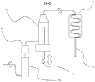
- FIG. 4 is a schematic view of a flow path of the second reagent dispensing mechanism 66 with a reagent temperature raising function in the embodiment of the present invention.
- the second reagent dispensing mechanism 66 with a reagent heating function includes a reagent probe 71, a reagent heating heat block 72, a reagent dispensing syringe 73, a plunger 74, an electromagnetic valve 75, and a fluid temperature control mechanism 76.
- the inside is filled with an internal fluid (for example, ion-exchanged water).
- the solenoid valve 75 By moving the plunger 74 up and down with the solenoid valve 75 closed, the reagent can be discharged / sucked from the tip of the reagent probe 71.
- the solenoid valve 75 is opened, the internal fluid to which pressure is applied flows in the flow path. By flowing and flowing out from the tip of the reagent probe 71, the inside of the flow path can be cleaned.
- the fluid temperature control mechanism 76 controls the temperature of the internal fluid of the reagent dispensing syringe 73, and comprises, for example, a heater for warming the fluid in the flow path and a control mechanism for controlling the heater. Warm and hold. As a result, even when the outside air temperature of the apparatus or the water temperature supplied to the apparatus fluctuates, the flow path to the tip of the reagent probe 71 is substantially constant in the process of discharging the fluid warmed to a fixed value from the reagent probe 71 Thus, stable temperature rise of the reagent and reproducible reagent dispensing can be realized.
- the air temperature can be controlled to a constant temperature. Thereby, more stable temperature rise of the reagent and high dispensing accuracy can be realized.
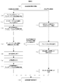
- FIG. 5 shows an example of a coagulation time measurement sequence according to an embodiment of the present invention.
- the temperature rise of the sample discharged into the disposable reaction container 62 is performed by the coagulation time detection unit 61 provided in the reaction container temperature control block 60 of the coagulation time measurement unit (b to d), and the reagent preheat (37 ° C.) is biochemical It is carried out in the reaction cell 11 on the reaction disc 10 of the analysis part (i to j). By this preheating, the temperature of the reagent before suction is controlled to a constant temperature. The reagent that has been preheated to 37 ° C.
- the second reagent dispensing mechanism 66 is further heated (eg, 39 ° C.) by the second reagent dispensing mechanism 66 with a reagent temperature rising function, and placed in the disposable reaction container 62 containing a sample already heated to 37 ° C. It is exhaled and the blood coagulation reaction starts (e). After completion of the reaction (f), the coagulation time is calculated (g), and the disposable reaction container 62 is discarded to the reaction container discarding part 67 (h).
- the third reagent dispensing mechanism 34b discharges washing water or detergent to the reaction cell 11 after suction of the preheated reagent (k), and then the reaction cell washing mechanism 36 cleans it (l).
- the temperature inside the coagulation time measuring unit cover 68 is maintained constant at a temperature lower than 37 ° C. (eg 30 ° C.), and the reagent preheated to 37 ° C. in the reaction cell 11 is a reagent
- the temperature is raised to a temperature higher than 37 ° C. (for example, 39 ° C.) from the probe 71 into the reagent temperature rising heat block 72, and the temperature is adjusted to 37 ° C. with the sample by the reaction vessel temperature adjustment block 60
- the temperature of the internal fluid is controlled by the fluid temperature control mechanism 76 to a temperature (eg, 30.degree. C.) lower than that of the reagent temperature raising heat block 72.
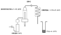
- FIG. 6 shows an example of the temperature control state around the reagent dispensing mechanism with temperature rising function according to the embodiment of the present invention.
- both the internal fluid and the internal fluid in the coagulation time measurement unit cover 68 are at 30 ° C.
- about the same of +/- 2 degrees C is accept
- the preheating temperature of the reagent and the temperature of the reagent heating block 72 be as close as possible, and the preheating temperature of the reagent be equal to or less than the reagent heating block temperature.
- the preheating temperature of the reagent is controlled to 37 ° C.
- the temperature rising heat block temperature of the reagent is controlled to 39 ° C.
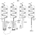
- FIGS. 7 a to 7 d show the flow of the dispensing operation in the case where the segment air is suctioned in the coagulation time measuring unit cover 68 in the embodiment of the present invention.
- Segment air is necessary to prevent dilution of the reagent due to internal fluid, but the volume fluctuates due to temperature change, which greatly affects the dispensing accuracy and reproducibility, etc.
- the control of the air flow and the control of the segmental air temperature change after suction are very important.
- the temperature change of the segment air is controlled at 30 ° C. ⁇ 39 ° C.
- FIGS. 8 a-d show the flow of the dispensing operation when segment air is aspirated in the reaction cell in one embodiment of the present invention.
- the importance of control of the segment air temperature during suction and control of the segment air temperature change after suction is as described above, but the volume change of the segment air is made smaller by minimizing the temperature change of the segment air as much as possible. It is possible to improve the dispensing accuracy.
- the temperature change of the segmented air is shown as 37 ° C. ⁇ 39 ° C. and 30 ° C. ⁇ 39 ° C. by sucking the segment air in the reaction cell, ie at a position lower than the opening face of the reaction cell. It is smaller than it is. Therefore, further improvement of the dispensing accuracy can be expected.
- the temperature in the coagulation time measuring unit cover 68 is controlled in the range of 30 ⁇ several degrees Celsius, but the temperature of the thermostat 12 used for temperature control of the reaction cell 11 is 37 ⁇ 0.1 degrees Celsius Because it is controlled by, it is possible to more stable segment air temperature control.
- FIG. 9 is a view showing a second reagent dispensing mechanism 66 with a temperature rising function provided with a block for making the temperature around the reagent dispensing probe constant at the time of discharging the reagent in the embodiment of the present invention.
- the pre-dispensing heat block 77 is provided with a through hole through which the reagent dispensing probe can be passed and which is controlled to a constant temperature (eg 37 ⁇ 0.3 ° C.)
- a constant temperature eg 37 ⁇ 0.3 ° C.
- the pre-dispensing heat block 77 is provided at a position different from the reagent aspirating position, the reagent is aspirated without inserting the reagent dispensing probe into the pre-dispensing heat block 77.
- the pre-dispensing heat block 77 may be provided also at the reagent suction position, the number of parts of the pre-dispensing heat block 77 can be reduced as compared with the case where it is not provided.
- FIG. 10 additionally illustrates an installation example of the heat block 77 before dispensing.
- the pre-dispensing heat block 77 is placed at a midpoint between the reagent suction position and the coagulation time detection unit 61. After aspirating the reagent, it takes several seconds (for example, 3 to 4 seconds) to raise the temperature of the reagent by the second reagent dispensing mechanism with reagent temperature rising function 66. By raising the temperature of the reagent in the inserted state, it is possible to suppress the temperature fluctuation of the reagent dispensing probe. Furthermore, the reagent dispensing probe is inserted into the disposable reaction container 62 whose temperature is adjusted to 37 ° C. by the reaction container temperature adjustment block 60 to discharge the reagent, whereby the reagent temperature at the time of discharge can be stabilized.
- reaction container temperature control block 60 and the pre-dispensing heat block 77 were shared, and the reagent dispensing probe was moved to the coagulation time detection unit 61 promptly after the reagent was aspirated, and the reagent dispensing probe was temperature controlled at 37 ° C.
- a configuration is also possible in which the temperature of the reagent is raised and discharged in a state of being inserted into the disposable reaction container 62.
Landscapes
- Health & Medical Sciences (AREA)
- Life Sciences & Earth Sciences (AREA)
- Chemical & Material Sciences (AREA)
- Engineering & Computer Science (AREA)
- Physics & Mathematics (AREA)
- Immunology (AREA)
- General Physics & Mathematics (AREA)
- Analytical Chemistry (AREA)
- General Health & Medical Sciences (AREA)
- Pathology (AREA)
- Biochemistry (AREA)
- Biomedical Technology (AREA)
- Hematology (AREA)
- Molecular Biology (AREA)
- Urology & Nephrology (AREA)
- Food Science & Technology (AREA)
- Medicinal Chemistry (AREA)
- Quality & Reliability (AREA)
- Chemical Kinetics & Catalysis (AREA)
- Ecology (AREA)
- Biophysics (AREA)
- Microbiology (AREA)
- Cell Biology (AREA)
- Biotechnology (AREA)
- Automatic Analysis And Handling Materials Therefor (AREA)
- Investigating Or Analysing Biological Materials (AREA)
Abstract
Priority Applications (6)
| Application Number | Priority Date | Filing Date | Title |
|---|---|---|---|
| EP18205813.1A EP3527991B1 (fr) | 2012-12-26 | 2013-12-13 | Analyseur automatique |
| EP13868392.5A EP2940477B1 (fr) | 2012-12-26 | 2013-12-13 | Analyseur automatique |
| US14/651,684 US9835612B2 (en) | 2012-12-26 | 2013-12-13 | Automatic analyzer |
| JP2014554315A JP6072832B2 (ja) | 2012-12-26 | 2013-12-13 | 自動分析装置 |
| CN201380066008.1A CN104871007A (zh) | 2012-12-26 | 2013-12-13 | 自动分析装置 |
| US15/812,150 US10788479B2 (en) | 2012-12-26 | 2017-11-14 | Automatic analyzer |
Applications Claiming Priority (2)
| Application Number | Priority Date | Filing Date | Title |
|---|---|---|---|
| JP2012281936 | 2012-12-26 | ||
| JP2012-281936 | 2012-12-26 |
Related Child Applications (2)
| Application Number | Title | Priority Date | Filing Date |
|---|---|---|---|
| US14/651,684 A-371-Of-International US9835612B2 (en) | 2012-12-26 | 2013-12-13 | Automatic analyzer |
| US15/812,150 Continuation US10788479B2 (en) | 2012-12-26 | 2017-11-14 | Automatic analyzer |
Publications (1)
| Publication Number | Publication Date |
|---|---|
| WO2014103744A1 true WO2014103744A1 (fr) | 2014-07-03 |
Family
ID=51020833
Family Applications (1)
| Application Number | Title | Priority Date | Filing Date |
|---|---|---|---|
| PCT/JP2013/083407 Ceased WO2014103744A1 (fr) | 2012-12-26 | 2013-12-13 | Analyseur automatique |
Country Status (5)
| Country | Link |
|---|---|
| US (2) | US9835612B2 (fr) |
| EP (2) | EP3527991B1 (fr) |
| JP (2) | JP6072832B2 (fr) |
| CN (1) | CN104871007A (fr) |
| WO (1) | WO2014103744A1 (fr) |
Cited By (23)
| Publication number | Priority date | Publication date | Assignee | Title |
|---|---|---|---|---|
| CN105548132A (zh) * | 2015-11-23 | 2016-05-04 | 王治才 | 自动化转盘式荧光检测仪 |
| EP3001196A3 (fr) * | 2014-09-29 | 2016-06-29 | C A Casyso AG | Système et procédé de test de sang |
| JP2017037073A (ja) * | 2015-08-11 | 2017-02-16 | シーメンス ヘルスケア ダイアグノスティクス プロダクツ ゲゼルシヤフト ミツト ベシユレンクテル ハフツング | 2つの温度センサを有する分注デバイス |
| WO2017082142A1 (fr) * | 2015-11-13 | 2017-05-18 | コニカミノルタ株式会社 | Système d'inspection |
| US9739789B2 (en) | 2008-12-23 | 2017-08-22 | C A Casyso Ag | Cartridge device for a measuring system for measuring viscoelastic characteristics of a sample liquid, a corresponding measuring system, and a corresponding method |
| CN107561302A (zh) * | 2017-10-23 | 2018-01-09 | 苏州卡睿知光电科技有限公司 | 一种全自动生化检测系统及农药残留的检测方法 |
| US9897618B2 (en) | 2014-09-29 | 2018-02-20 | C A Casyso Gmbh | Blood testing system |
| WO2018047545A1 (fr) * | 2016-09-08 | 2018-03-15 | 株式会社 日立ハイテクノロジーズ | Analyseur automatique |
| WO2018168308A1 (fr) * | 2017-03-17 | 2018-09-20 | コニカミノルタ株式会社 | Système de détection d'échantillon |
| JPWO2017141626A1 (ja) * | 2016-02-19 | 2018-12-06 | 株式会社日立ハイテクノロジーズ | 自動分析装置 |
| CN109085367A (zh) * | 2018-07-31 | 2018-12-25 | 美德太平洋(天津)生物科技股份有限公司 | 一种携带方便且具备防护装置的凝血仪 |
| WO2019000392A1 (fr) * | 2017-06-30 | 2019-01-03 | 深圳迈瑞生物医疗电子股份有限公司 | Ensemble de réaction, analyseur d'échantillon et procédé de mélange |
| US10288630B2 (en) | 2014-09-29 | 2019-05-14 | C A Casyso Gmbh | Blood testing system and method |
| JP2019074412A (ja) * | 2017-10-16 | 2019-05-16 | キヤノンメディカルシステムズ株式会社 | 分注制御装置、分注制御方法及び分注制御プログラム |
| US10295554B2 (en) | 2015-06-29 | 2019-05-21 | C A Casyso Gmbh | Blood testing system and method |
| US10473674B2 (en) | 2016-08-31 | 2019-11-12 | C A Casyso Gmbh | Controlled blood delivery to mixing chamber of a blood testing cartridge |
| US10539579B2 (en) | 2014-09-29 | 2020-01-21 | C A Casyso Gmbh | Blood testing system and method |
| WO2020054172A1 (fr) | 2018-09-10 | 2020-03-19 | 株式会社日立ハイテクノロジーズ | Analyseur automatisé |
| US10816559B2 (en) | 2014-09-29 | 2020-10-27 | Ca Casyso Ag | Blood testing system and method |
| US10843185B2 (en) | 2017-07-12 | 2020-11-24 | Ca Casyso Gmbh | Autoplatelet cartridge device |
| JP2021165744A (ja) * | 2016-12-13 | 2021-10-14 | 株式会社日立ハイテク | 自動分析装置 |
| JPWO2023188795A1 (fr) * | 2022-03-28 | 2023-10-05 | ||
| JP2023146770A (ja) * | 2022-03-29 | 2023-10-12 | キヤノンメディカルシステムズ株式会社 | 自動分析装置 |
Families Citing this family (24)
| Publication number | Priority date | Publication date | Assignee | Title |
|---|---|---|---|---|
| WO2014103744A1 (fr) * | 2012-12-26 | 2014-07-03 | 株式会社 日立ハイテクノロジーズ | Analyseur automatique |
| US10761000B2 (en) | 2014-07-18 | 2020-09-01 | Hitachi High-Tech Corporation | Liquid stirring method |
| BR112017019455A2 (pt) | 2015-03-19 | 2018-05-15 | Beckman Coulter Inc | dispensador para um analisador |
| JP6689597B2 (ja) * | 2015-11-27 | 2020-04-28 | シスメックス株式会社 | 血液凝固分析装置 |
| US10870110B2 (en) | 2015-12-11 | 2020-12-22 | Babson Diagnostics, Inc. | Specimen container and centrifugation method for separating serum or plasma from whole blood therewith |
| CN110291377B (zh) * | 2016-11-14 | 2023-09-05 | 巴布森诊断公司 | 样本制备装置 |
| JP6937116B2 (ja) * | 2016-12-15 | 2021-09-22 | シスメックス株式会社 | 前処理装置及び前処理方法 |
| JP6807778B2 (ja) * | 2017-03-06 | 2021-01-06 | テラメックス株式会社 | ピペットチップ先端検知装置、ピペットチップ先端検知プログラム |
| CN106918715B (zh) * | 2017-04-27 | 2019-02-15 | 南京诺尔曼生物技术有限公司 | 一种化学发光诊断装置及其系统 |
| CN107085119B (zh) * | 2017-04-27 | 2019-07-19 | 南京诺尔曼生物技术有限公司 | 一种化学发光快速诊断的预温育装置、预温育组件及方法 |
| WO2018220430A1 (fr) | 2017-06-02 | 2018-12-06 | Arcelormittal | Tôle d'acier destinée à la fabrication de pièces trempées à la presse, pièce trempée à la presse présentant une association de résistance élevée et de ductilité d'impact, et procédés de fabrication de cette dernière |
| EP3779459A4 (fr) * | 2018-04-05 | 2021-05-05 | Konica Minolta, Inc. | Système et procédé de réglage de température |
| JP7157658B2 (ja) * | 2018-12-27 | 2022-10-20 | 株式会社日立ハイテク | 自動分析装置 |
| JP7229060B2 (ja) * | 2019-03-26 | 2023-02-27 | 株式会社日立ハイテク | 自動分析装置 |
| EP4033251B1 (fr) * | 2019-09-19 | 2024-05-22 | Hitachi High-Tech Corporation | Dispositif d'analyse automatisé et procédé permettant de mettre à niveau celui-ci |
| WO2021134609A1 (fr) * | 2019-12-31 | 2021-07-08 | 深圳迈瑞生物医疗电子股份有限公司 | Appareil d'analyse d'échantillons |
| JP7417463B2 (ja) * | 2020-04-24 | 2024-01-18 | 株式会社日立ハイテク | 分注装置、自動分析装置、分注方法 |
| CN111751341B (zh) * | 2020-06-24 | 2023-06-02 | 新乡市食品药品检验所 | 一种中药材成分荧光分析检测仪和分析检测方法 |
| JP7797505B2 (ja) * | 2020-11-30 | 2026-01-13 | ベックマン コールター, インコーポレイテッド | 混合ヒータの設定値変更 |
| CN113502397B (zh) * | 2021-06-18 | 2022-11-04 | 昆明鼎邦科技股份有限公司 | 一种连续硫化生产设备 |
| US12050052B1 (en) | 2021-08-06 | 2024-07-30 | Babson Diagnostics, Inc. | Refrigerated carrier device for biological samples |
| US12050232B2 (en) | 2021-12-31 | 2024-07-30 | Instrumentation Laboratory Company | Systems and methods for probe tip heating |
| EP4505185A1 (fr) | 2022-04-06 | 2025-02-12 | Babson Diagnostics, Inc. | Chargeur automatisé de centrifugeuse |
| CN118049770B (zh) * | 2024-04-16 | 2024-07-02 | 深圳赛陆医疗科技有限公司 | 基于废热利用的基因测序预热系统 |
Citations (11)
| Publication number | Priority date | Publication date | Assignee | Title |
|---|---|---|---|---|
| JPH0337641A (ja) | 1989-07-04 | 1991-02-19 | Fuji Photo Film Co Ltd | ハロゲン化銀写真感光材料を用いた画像形成方法 |
| JPH05119041A (ja) * | 1991-10-28 | 1993-05-14 | Shimadzu Corp | 試料測定装置 |
| JPH0640837U (ja) * | 1992-10-30 | 1994-05-31 | 株式会社島津製作所 | 分注装置 |
| JP3037641U (ja) * | 1996-11-09 | 1997-05-20 | 株式会社八光電機製作所 | ヒーター付ピペットノズル |
| JP2000321286A (ja) | 1999-05-10 | 2000-11-24 | Shimadzu Corp | 血液凝固分析装置 |
| JP2004037161A (ja) | 2002-07-01 | 2004-02-05 | Sysmex Corp | 試料分析装置 |
| JP2008070355A (ja) | 2006-08-18 | 2008-03-27 | Sysmex Corp | 分注装置、試薬分注装置および検体分析装置 |
| JP2008203009A (ja) | 2007-02-19 | 2008-09-04 | Hitachi High-Technologies Corp | 自動分析装置 |
| JP2010286243A (ja) * | 2009-06-09 | 2010-12-24 | Hitachi High-Technologies Corp | 自動分析装置 |
| JP2011099681A (ja) * | 2009-11-04 | 2011-05-19 | Hitachi High-Technologies Corp | 自動分析装置 |
| JP2012159392A (ja) * | 2011-01-31 | 2012-08-23 | Sysmex Corp | 分析装置及び分析方法 |
Family Cites Families (16)
| Publication number | Priority date | Publication date | Assignee | Title |
|---|---|---|---|---|
| JPS57132063A (en) * | 1981-02-10 | 1982-08-16 | Olympus Optical Co Ltd | Method for automatic chemical analysis |
| US6498037B1 (en) * | 1991-03-04 | 2002-12-24 | Bayer Corporation | Method of handling reagents in a random access protocol |
| JP3000419B2 (ja) * | 1994-03-15 | 2000-01-17 | 松下電器産業株式会社 | 高周波加熱方法および高周波加熱装置 |
| JP3037641B2 (ja) * | 1996-08-28 | 2000-04-24 | 内山 充子 | ゴルフウッドクラブ |
| US8337753B2 (en) * | 1998-05-01 | 2012-12-25 | Gen-Probe Incorporated | Temperature-controlled incubator having a receptacle mixing mechanism |
| JP2001108691A (ja) * | 1999-10-06 | 2001-04-20 | Tosoh Corp | 試薬の自動加温分注装置 |
| JP2007322327A (ja) * | 2006-06-02 | 2007-12-13 | Olympus Corp | 分注装置および自動分析装置 |
| ES2628614T3 (es) * | 2006-08-18 | 2017-08-03 | Perkinelmer, Inc. | Dispositivos para hacer circular aire en un sistema de cromatografía de gases |
| JP5164388B2 (ja) * | 2007-01-31 | 2013-03-21 | シスメックス株式会社 | 試料測定装置 |
| JP2010048695A (ja) * | 2008-08-22 | 2010-03-04 | Olympus Corp | 自動分析装置および恒温槽安定化方法 |
| JP2010237021A (ja) * | 2009-03-31 | 2010-10-21 | Sysmex Corp | 分析装置 |
| US20120048036A1 (en) * | 2009-04-09 | 2012-03-01 | Hitachi High-Technologies Corporation | Automatic analysis apparatus |
| JP4811797B2 (ja) * | 2010-01-26 | 2011-11-09 | 株式会社日立プラントテクノロジー | 発光測定装置の配管洗浄方法、発光測定装置の配管洗浄機構 |
| JP2011191114A (ja) * | 2010-03-12 | 2011-09-29 | Sysmex Corp | 分析装置 |
| EP2860528B1 (fr) * | 2012-06-11 | 2018-01-03 | Hitachi High-Technologies Corporation | Appareil d'analyse automatique |
| WO2014103744A1 (fr) * | 2012-12-26 | 2014-07-03 | 株式会社 日立ハイテクノロジーズ | Analyseur automatique |
-
2013
- 2013-12-13 WO PCT/JP2013/083407 patent/WO2014103744A1/fr not_active Ceased
- 2013-12-13 JP JP2014554315A patent/JP6072832B2/ja active Active
- 2013-12-13 EP EP18205813.1A patent/EP3527991B1/fr active Active
- 2013-12-13 EP EP13868392.5A patent/EP2940477B1/fr active Active
- 2013-12-13 CN CN201380066008.1A patent/CN104871007A/zh active Pending
- 2013-12-13 US US14/651,684 patent/US9835612B2/en active Active
-
2016
- 2016-12-28 JP JP2016255944A patent/JP6475222B2/ja active Active
-
2017
- 2017-11-14 US US15/812,150 patent/US10788479B2/en active Active
Patent Citations (11)
| Publication number | Priority date | Publication date | Assignee | Title |
|---|---|---|---|---|
| JPH0337641A (ja) | 1989-07-04 | 1991-02-19 | Fuji Photo Film Co Ltd | ハロゲン化銀写真感光材料を用いた画像形成方法 |
| JPH05119041A (ja) * | 1991-10-28 | 1993-05-14 | Shimadzu Corp | 試料測定装置 |
| JPH0640837U (ja) * | 1992-10-30 | 1994-05-31 | 株式会社島津製作所 | 分注装置 |
| JP3037641U (ja) * | 1996-11-09 | 1997-05-20 | 株式会社八光電機製作所 | ヒーター付ピペットノズル |
| JP2000321286A (ja) | 1999-05-10 | 2000-11-24 | Shimadzu Corp | 血液凝固分析装置 |
| JP2004037161A (ja) | 2002-07-01 | 2004-02-05 | Sysmex Corp | 試料分析装置 |
| JP2008070355A (ja) | 2006-08-18 | 2008-03-27 | Sysmex Corp | 分注装置、試薬分注装置および検体分析装置 |
| JP2008203009A (ja) | 2007-02-19 | 2008-09-04 | Hitachi High-Technologies Corp | 自動分析装置 |
| JP2010286243A (ja) * | 2009-06-09 | 2010-12-24 | Hitachi High-Technologies Corp | 自動分析装置 |
| JP2011099681A (ja) * | 2009-11-04 | 2011-05-19 | Hitachi High-Technologies Corp | 自動分析装置 |
| JP2012159392A (ja) * | 2011-01-31 | 2012-08-23 | Sysmex Corp | 分析装置及び分析方法 |
Cited By (59)
| Publication number | Priority date | Publication date | Assignee | Title |
|---|---|---|---|---|
| US11768211B2 (en) | 2008-12-23 | 2023-09-26 | C A Casyso Gmbh | Cartridge device for a measuring system for measuring viscoelastic characteristics of a sample liquid, a corresponding measuring system, and a corresponding method |
| US11879899B2 (en) | 2008-12-23 | 2024-01-23 | C A Casyso Gmbh | Cartridge device for a measuring system for measuring viscoelastic characteristics of a sample liquid, a corresponding measuring system, and a corresponding method |
| US11892459B2 (en) | 2008-12-23 | 2024-02-06 | C A Casyso Gmbh | Cartridge device for a measuring system for measuring viscoelastic characteristics of a sample liquid, a corresponding measuring system, and a corresponding method |
| US11360106B2 (en) | 2008-12-23 | 2022-06-14 | C A Casyso Gmbh | Cartridge device for a measuring system for measuring viscoelastic characteristics of a sample liquid, a corresponding measuring system, and a corresponding method |
| US11131680B2 (en) | 2008-12-23 | 2021-09-28 | C A Casyso Gmbh | Cartridge device for a measuring system for measuring viscoelastic characteristics of a sample liquid, a corresponding measuring system, and a corresponding method |
| US9739789B2 (en) | 2008-12-23 | 2017-08-22 | C A Casyso Ag | Cartridge device for a measuring system for measuring viscoelastic characteristics of a sample liquid, a corresponding measuring system, and a corresponding method |
| US11061038B2 (en) | 2008-12-23 | 2021-07-13 | C A Casyso Gmbh | Cartridge device for a measuring system for measuring viscoelastic characteristics of a sample liquid, a corresponding measuring system, and a corresponding method |
| US10996230B2 (en) | 2008-12-23 | 2021-05-04 | C A Casyso Gmbh | Cartridge device for a measuring system for measuring viscoelastic characteristics of a sample liquid, a corresponding measuring system, and a corresponding method |
| US9915671B2 (en) | 2008-12-23 | 2018-03-13 | C A Casyso Ag | Cartridge device for a measuring system for measuring viscoelastic characteristics of a sample liquid, a corresponding measuring system, and a corresponding method |
| US12105103B2 (en) | 2008-12-23 | 2024-10-01 | C A Casyso Gmbh | Cartridge device for a measuring system for measuring viscoelastic characteristics of a sample liquid, a corresponding measuring system, and a corresponding method |
| US10746750B2 (en) | 2008-12-23 | 2020-08-18 | C A Casyso Gmbh | Cartridge device for a measuring system for measuring viscoelastic characteristics of a sample liquid, a corresponding measuring system, and a corresponding method |
| US12111326B2 (en) | 2008-12-23 | 2024-10-08 | C A Casyso Gmbh | Cartridge device for a measuring system for measuring viscoelastic characteristics of a sample liquid, a corresponding measuring system, and a corresponding method |
| US10539579B2 (en) | 2014-09-29 | 2020-01-21 | C A Casyso Gmbh | Blood testing system and method |
| US12031993B2 (en) | 2014-09-29 | 2024-07-09 | C A Casyso Gmbh | Blood testing system and method |
| US12578349B2 (en) | 2014-09-29 | 2026-03-17 | Ca Casyso Gmbh | Blood testing system and method |
| US10175225B2 (en) | 2014-09-29 | 2019-01-08 | C A Casyso Ag | Blood testing system and method |
| US10288630B2 (en) | 2014-09-29 | 2019-05-14 | C A Casyso Gmbh | Blood testing system and method |
| EP3001196A3 (fr) * | 2014-09-29 | 2016-06-29 | C A Casyso AG | Système et procédé de test de sang |
| US9897618B2 (en) | 2014-09-29 | 2018-02-20 | C A Casyso Gmbh | Blood testing system |
| US11719688B2 (en) | 2014-09-29 | 2023-08-08 | C A Casyso Gmbh | Blood testing system and method |
| US10816559B2 (en) | 2014-09-29 | 2020-10-27 | Ca Casyso Ag | Blood testing system and method |
| US11327069B2 (en) | 2014-09-29 | 2022-05-10 | Ca Casyso Gmbh | Blood testing system and method |
| US11085938B2 (en) | 2015-06-29 | 2021-08-10 | C A Casyso Gmbh | Thromboelastometry blood testing system and accuracy control methods |
| US10295554B2 (en) | 2015-06-29 | 2019-05-21 | C A Casyso Gmbh | Blood testing system and method |
| CN106443038A (zh) * | 2015-08-11 | 2017-02-22 | 西门子医学诊断产品有限责任公司 | 具有两个温度传感器的移液装置 |
| JP2017037073A (ja) * | 2015-08-11 | 2017-02-16 | シーメンス ヘルスケア ダイアグノスティクス プロダクツ ゲゼルシヤフト ミツト ベシユレンクテル ハフツング | 2つの温度センサを有する分注デバイス |
| CN106443038B (zh) * | 2015-08-11 | 2020-11-06 | 西门子医学诊断产品有限责任公司 | 具有两个温度传感器的移液装置 |
| JPWO2017082142A1 (ja) * | 2015-11-13 | 2018-08-30 | コニカミノルタ株式会社 | 検査システム |
| WO2017082142A1 (fr) * | 2015-11-13 | 2017-05-18 | コニカミノルタ株式会社 | Système d'inspection |
| US11079331B2 (en) | 2015-11-13 | 2021-08-03 | Konica Minolta, Inc. | Inspection system |
| CN105548132A (zh) * | 2015-11-23 | 2016-05-04 | 王治才 | 自动化转盘式荧光检测仪 |
| JPWO2017141626A1 (ja) * | 2016-02-19 | 2018-12-06 | 株式会社日立ハイテクノロジーズ | 自動分析装置 |
| US10473674B2 (en) | 2016-08-31 | 2019-11-12 | C A Casyso Gmbh | Controlled blood delivery to mixing chamber of a blood testing cartridge |
| US12399187B2 (en) | 2016-08-31 | 2025-08-26 | Ca Casyso Gmbh | Controlled blood delivery to mixing chamber of a blood testing cartridge |
| WO2018047545A1 (fr) * | 2016-09-08 | 2018-03-15 | 株式会社 日立ハイテクノロジーズ | Analyseur automatique |
| US10690688B2 (en) | 2016-09-08 | 2020-06-23 | Hitachi High-Tech Corporation | Automatic analyzer |
| JPWO2018047545A1 (ja) * | 2016-09-08 | 2019-06-24 | 株式会社日立ハイテクノロジーズ | 自動分析装置 |
| JP2021165744A (ja) * | 2016-12-13 | 2021-10-14 | 株式会社日立ハイテク | 自動分析装置 |
| JP7260594B2 (ja) | 2016-12-13 | 2023-04-18 | 株式会社日立ハイテク | 自動分析装置 |
| JP2023076674A (ja) * | 2016-12-13 | 2023-06-01 | 株式会社日立ハイテク | 自動分析装置 |
| JP7570454B2 (ja) | 2016-12-13 | 2024-10-21 | 株式会社日立ハイテク | 自動分析装置 |
| WO2018168308A1 (fr) * | 2017-03-17 | 2018-09-20 | コニカミノルタ株式会社 | Système de détection d'échantillon |
| JP7093766B2 (ja) | 2017-03-17 | 2022-06-30 | 大塚製薬株式会社 | 検体検出システム |
| JPWO2018168308A1 (ja) * | 2017-03-17 | 2020-01-16 | コニカミノルタ株式会社 | 検体検出システム |
| WO2019000392A1 (fr) * | 2017-06-30 | 2019-01-03 | 深圳迈瑞生物医疗电子股份有限公司 | Ensemble de réaction, analyseur d'échantillon et procédé de mélange |
| US10843185B2 (en) | 2017-07-12 | 2020-11-24 | Ca Casyso Gmbh | Autoplatelet cartridge device |
| US11691142B2 (en) | 2017-07-12 | 2023-07-04 | Ca Casyso Gmbh | Autoplatelet cartridge device |
| JP2019074412A (ja) * | 2017-10-16 | 2019-05-16 | キヤノンメディカルシステムズ株式会社 | 分注制御装置、分注制御方法及び分注制御プログラム |
| JP7138423B2 (ja) | 2017-10-16 | 2022-09-16 | キヤノンメディカルシステムズ株式会社 | 分注制御装置 |
| CN107561302B (zh) * | 2017-10-23 | 2024-02-20 | 苏州卡睿知光电科技有限公司 | 一种全自动生化检测系统及农药残留的检测方法 |
| CN107561302A (zh) * | 2017-10-23 | 2018-01-09 | 苏州卡睿知光电科技有限公司 | 一种全自动生化检测系统及农药残留的检测方法 |
| CN109085367B (zh) * | 2018-07-31 | 2023-09-26 | 美德太平洋(天津)生物科技股份有限公司 | 一种携带方便且具备防护装置的凝血仪 |
| CN109085367A (zh) * | 2018-07-31 | 2018-12-25 | 美德太平洋(天津)生物科技股份有限公司 | 一种携带方便且具备防护装置的凝血仪 |
| US11906534B2 (en) | 2018-09-10 | 2024-02-20 | Hitachi High-Tech Corporation | Automatic analyzer |
| WO2020054172A1 (fr) | 2018-09-10 | 2020-03-19 | 株式会社日立ハイテクノロジーズ | Analyseur automatisé |
| JPWO2023188795A1 (fr) * | 2022-03-28 | 2023-10-05 | ||
| JP7766787B2 (ja) | 2022-03-28 | 2025-11-10 | 株式会社日立ハイテク | 自動分析装置 |
| WO2023188795A1 (fr) * | 2022-03-28 | 2023-10-05 | 株式会社日立ハイテク | Dispositif d'analyse automatique |
| JP2023146770A (ja) * | 2022-03-29 | 2023-10-12 | キヤノンメディカルシステムズ株式会社 | 自動分析装置 |
Also Published As
| Publication number | Publication date |
|---|---|
| EP2940477A4 (fr) | 2016-08-31 |
| EP3527991A1 (fr) | 2019-08-21 |
| CN104871007A (zh) | 2015-08-26 |
| EP3527991B1 (fr) | 2020-04-22 |
| US20150316532A1 (en) | 2015-11-05 |
| JPWO2014103744A1 (ja) | 2017-01-12 |
| JP2017083469A (ja) | 2017-05-18 |
| US20180074043A1 (en) | 2018-03-15 |
| EP2940477A1 (fr) | 2015-11-04 |
| JP6072832B2 (ja) | 2017-02-01 |
| US9835612B2 (en) | 2017-12-05 |
| EP2940477B1 (fr) | 2019-02-20 |
| JP6475222B2 (ja) | 2019-02-27 |
| US10788479B2 (en) | 2020-09-29 |
Similar Documents
| Publication | Publication Date | Title |
|---|---|---|
| JP6475222B2 (ja) | 自動分析装置 | |
| JP7035130B2 (ja) | 自動分析装置 | |
| BRPI0717331B1 (pt) | Dispositivo para ajuste automático do nível do inóculo bacteriano de uma amostra | |
| JP5236612B2 (ja) | 自動分析装置 | |
| CN107430139A (zh) | 自动分析装置以及自动分析方法 | |
| WO2007129741A1 (fr) | Analyseur automatique | |
| JP2014126415A (ja) | 自動分析装置 | |
| JP6077075B2 (ja) | 自動分析装置 | |
| JP6151096B2 (ja) | 自動分析装置 | |
| JP2590688Y2 (ja) | 血液凝固分析装置 | |
| JP7844177B2 (ja) | 自動分析装置 | |
| JP5806769B2 (ja) | 分析方法、分注方法および昇温方法 | |
| JP5604551B2 (ja) | 自動分析装置 | |
| WO2026069877A1 (fr) | Système de détection d'anomalies de voie d'écoulement, dispositif d'analyse automatique et procédé de détection d'anomalies de voie d'écoulement | |
| JP2015004528A (ja) | 自動分析装置 |
Legal Events
| Date | Code | Title | Description |
|---|---|---|---|
| 121 | Ep: the epo has been informed by wipo that ep was designated in this application |
Ref document number: 13868392 Country of ref document: EP Kind code of ref document: A1 |
|
| ENP | Entry into the national phase |
Ref document number: 2014554315 Country of ref document: JP Kind code of ref document: A |
|
| WWE | Wipo information: entry into national phase |
Ref document number: 2013868392 Country of ref document: EP |
|
| WWE | Wipo information: entry into national phase |
Ref document number: 14651684 Country of ref document: US |
|
| NENP | Non-entry into the national phase |
Ref country code: DE |