WO2014103809A1 - Système d'échange thermique - Google Patents
Système d'échange thermique Download PDFInfo
- Publication number
- WO2014103809A1 WO2014103809A1 PCT/JP2013/083798 JP2013083798W WO2014103809A1 WO 2014103809 A1 WO2014103809 A1 WO 2014103809A1 JP 2013083798 W JP2013083798 W JP 2013083798W WO 2014103809 A1 WO2014103809 A1 WO 2014103809A1
- Authority
- WO
- WIPO (PCT)
- Prior art keywords
- refrigerant
- cooling water
- exchange system
- heat exchange
- passage
- Prior art date
- Legal status (The legal status is an assumption and is not a legal conclusion. Google has not performed a legal analysis and makes no representation as to the accuracy of the status listed.)
- Ceased
Links
Images


Classifications
-
- F—MECHANICAL ENGINEERING; LIGHTING; HEATING; WEAPONS; BLASTING
- F01—MACHINES OR ENGINES IN GENERAL; ENGINE PLANTS IN GENERAL; STEAM ENGINES
- F01K—STEAM ENGINE PLANTS; STEAM ACCUMULATORS; ENGINE PLANTS NOT OTHERWISE PROVIDED FOR; ENGINES USING SPECIAL WORKING FLUIDS OR CYCLES
- F01K23/00—Plants characterised by more than one engine delivering power external to the plant, the engines being driven by different fluids
- F01K23/02—Plants characterised by more than one engine delivering power external to the plant, the engines being driven by different fluids the engine cycles being thermally coupled
- F01K23/06—Plants characterised by more than one engine delivering power external to the plant, the engines being driven by different fluids the engine cycles being thermally coupled combustion heat from one cycle heating the fluid in another cycle
- F01K23/065—Plants characterised by more than one engine delivering power external to the plant, the engines being driven by different fluids the engine cycles being thermally coupled combustion heat from one cycle heating the fluid in another cycle the combustion taking place in an internal combustion piston engine, e.g. a diesel engine
-
- B—PERFORMING OPERATIONS; TRANSPORTING
- B60—VEHICLES IN GENERAL
- B60W—CONJOINT CONTROL OF VEHICLE SUB-UNITS OF DIFFERENT TYPE OR DIFFERENT FUNCTION; CONTROL SYSTEMS SPECIALLY ADAPTED FOR HYBRID VEHICLES; ROAD VEHICLE DRIVE CONTROL SYSTEMS FOR PURPOSES NOT RELATED TO THE CONTROL OF A PARTICULAR SUB-UNIT
- B60W20/00—Control systems specially adapted for hybrid vehicles
- B60W20/10—Controlling the power contribution of each of the prime movers to meet required power demand
- B60W20/15—Control strategies specially adapted for achieving a particular effect
- B60W20/16—Control strategies specially adapted for achieving a particular effect for reducing engine exhaust emissions
-
- F—MECHANICAL ENGINEERING; LIGHTING; HEATING; WEAPONS; BLASTING
- F01—MACHINES OR ENGINES IN GENERAL; ENGINE PLANTS IN GENERAL; STEAM ENGINES
- F01K—STEAM ENGINE PLANTS; STEAM ACCUMULATORS; ENGINE PLANTS NOT OTHERWISE PROVIDED FOR; ENGINES USING SPECIAL WORKING FLUIDS OR CYCLES
- F01K15/00—Adaptations of plants for special use
- F01K15/02—Adaptations of plants for special use for driving vehicles, e.g. locomotives
-
- F—MECHANICAL ENGINEERING; LIGHTING; HEATING; WEAPONS; BLASTING
- F01—MACHINES OR ENGINES IN GENERAL; ENGINE PLANTS IN GENERAL; STEAM ENGINES
- F01K—STEAM ENGINE PLANTS; STEAM ACCUMULATORS; ENGINE PLANTS NOT OTHERWISE PROVIDED FOR; ENGINES USING SPECIAL WORKING FLUIDS OR CYCLES
- F01K9/00—Plants characterised by condensers arranged or modified to co-operate with the engines
- F01K9/003—Plants characterised by condensers arranged or modified to co-operate with the engines condenser cooling circuits
-
- F—MECHANICAL ENGINEERING; LIGHTING; HEATING; WEAPONS; BLASTING
- F01—MACHINES OR ENGINES IN GENERAL; ENGINE PLANTS IN GENERAL; STEAM ENGINES
- F01P—COOLING OF MACHINES OR ENGINES IN GENERAL; COOLING OF INTERNAL-COMBUSTION ENGINES
- F01P9/00—Cooling having pertinent characteristics not provided for in, or of interest apart from, groups F01P1/00 - F01P7/00
- F01P9/02—Cooling by evaporation, e.g. by spraying water on to cylinders
-
- F—MECHANICAL ENGINEERING; LIGHTING; HEATING; WEAPONS; BLASTING
- F02—COMBUSTION ENGINES; HOT-GAS OR COMBUSTION-PRODUCT ENGINE PLANTS
- F02G—HOT GAS OR COMBUSTION-PRODUCT POSITIVE-DISPLACEMENT ENGINE PLANTS; USE OF WASTE HEAT OF COMBUSTION ENGINES; NOT OTHERWISE PROVIDED FOR
- F02G5/00—Profiting from waste heat of combustion engines, not otherwise provided for
-
- Y—GENERAL TAGGING OF NEW TECHNOLOGICAL DEVELOPMENTS; GENERAL TAGGING OF CROSS-SECTIONAL TECHNOLOGIES SPANNING OVER SEVERAL SECTIONS OF THE IPC; TECHNICAL SUBJECTS COVERED BY FORMER USPC CROSS-REFERENCE ART COLLECTIONS [XRACs] AND DIGESTS
- Y02—TECHNOLOGIES OR APPLICATIONS FOR MITIGATION OR ADAPTATION AGAINST CLIMATE CHANGE
- Y02T—CLIMATE CHANGE MITIGATION TECHNOLOGIES RELATED TO TRANSPORTATION
- Y02T10/00—Road transport of goods or passengers
- Y02T10/10—Internal combustion engine [ICE] based vehicles
- Y02T10/12—Improving ICE efficiencies
Definitions
- This invention relates to a heat exchange system mounted on a hybrid vehicle.
- a Rankine condenser and an air conditioner condenser are usually arranged in the front end portion of the vehicle (see JP2011-84102A).
- An object of the present invention is to efficiently cool the working medium of the Rankine cycle.
- the heat exchange system is a heat exchange system mounted on a hybrid vehicle using the power of an engine and an electric motor.
- the heat exchange system includes a heat exchanger that recovers engine waste heat into a refrigerant, an expander that generates power using the refrigerant at the outlet of the heat exchanger, and a condenser that condenses the refrigerant that has left the expander. Has a Rankine cycle.
- the heat exchange system includes a control device that controls the electric motor and a cooling water passage through which cooling water that cools the control device flows, and the condenser is cooled by cooling water that cools the control device.
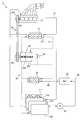
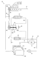
- FIG. 1 is a configuration diagram showing a heat exchange system according to the first embodiment of the present invention.
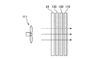
- FIG. 2A is a diagram showing an arrangement of radiators mounted on the hybrid vehicle.
- FIG. 2B is a diagram showing an example in which a Rankine cycle radiator is added to the radiator shown in FIG. 2A.
- FIG. 3 is a diagram showing the cooling capacity of a condenser sharing a radiator.
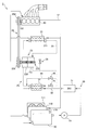
- FIG. 4 is a configuration diagram illustrating a heat exchange system according to the second embodiment.
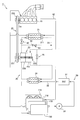
- FIG. 5 is a configuration diagram showing a heat exchange system according to the third embodiment.
- FIG. 6 is a configuration diagram showing a heat exchange system according to the fourth embodiment.
- FIG. 7 is a configuration diagram illustrating a heat exchange system according to the fifth embodiment.
- FIG. 8 is a configuration diagram illustrating a heat exchange system according to the sixth embodiment.
- FIG. 9 is a configuration diagram illustrating a heat exchange system according to the seventh embodiment.
- FIG. 1 is a diagram showing a heat exchange system according to the first embodiment of the present invention.
- the heat exchange system 1 is mounted on a hybrid vehicle that uses power from an engine and an electric motor.
- the heat exchange system 1 regenerates the waste heat energy of the engine 10 as power of the engine 10 using the Rankine cycle 20, and cools the inverter 31 using the cooling device 30.
- the heat exchange system 1 includes an engine 10, a cooling water passage 12, a heat exchanger 21, a refrigerant passage 22, a rotating machine 23, a condenser 24, a belt transmission mechanism 25, a cooling device 30, and a radiator 110. And a radiator fan 111.
- the rotating machine 23 includes an expander 231 and a refrigerant pump 232.
- the Rankine cycle 20 includes a heat exchanger 21 that recovers waste heat of the engine 10 into a refrigerant, an expander 231 that generates power using the refrigerant at the outlet 211 of the heat exchanger 21, and a refrigerant that has exited the expander 231.
- a condenser 24 for condensation is included in The Rankine cycle 20.
- the heat exchange system 1 uses the heat exchanger 21 to recover the waste heat of the engine 10 into the refrigerant of the Rankine cycle 20, and drives the expander 231 by expansion of the refrigerant.
- the driving force of the expander 231 is used as power for rotating the refrigerant pump 232 and is also used as power for assisting the engine 10 via the belt transmission mechanism 25.
- the refrigerant of Rankine cycle 20 is a working medium that operates expander 231.
- the heat exchanger 21 has a cooling water passage of the engine 10 and a refrigerant passage of the Rankine cycle 20.
- a cooling water passage 12 and a refrigerant passage 22 are connected to each passage of the heat exchanger 21.
- the heat exchanger 21 evaporates the refrigerant by using the waste heat of the engine 10 by flowing cooling water around the refrigerant passage and exchanging heat between the refrigerant and the cooling water.
- the engine 10 is a power source that drives the vehicle.
- the engine 10 burns gasoline and converts the combustion energy into rotational force of the crankshaft 101.
- the radiator fan 111 sends wind to the radiator 110 to cool the radiator 110.
- the radiator 110 cools the cooling water by the wind power of the radiator fan 111.
- the cooling water passage 12 includes a forward passage connecting the radiator 110 and the engine 10, a return passage connecting the engine 10 and the radiator 110, a branch passage branched from the return passage and connected to the inlet of the heat exchanger 21, and the heat exchanger 21. And a merging passage that merges from the exit to the outward path.
- the cooling water cooled by the radiator 110 circulates.
- the temperature rises to about 80 ° C. to 90 ° C.
- the refrigerant in the Rankine cycle 20 is vaporized and flows out from the heat exchanger 21 to the refrigerant passage 22.
- the refrigerant passage 22 includes a passage connecting the heat exchanger 21 and the expander 231, a passage connecting the expander 231 and the condenser 24, a passage connecting the condenser 24 and the refrigerant pump 232, and the refrigerant pump 232 and heat. And a passage connecting to the exchanger 21.
- the refrigerant passage 22 includes a bypass passage that branches from a passage connecting the heat exchanger 21 and the expander 231 and joins a passage connecting the expander 231 and the condenser 24.
- a bypass valve 26 is provided in the bypass passage. The bypass valve 26 opens when the amount of refrigerant flowing through the refrigerant passage 22 is not sufficient, for example, when the Rankine cycle 20 is started. Thereby, the starting time of Rankine cycle 20 is shortened.
- a temperature sensor, a pressure sensor, and the like provided in the refrigerant passage 22 are omitted.
- the expander 231 rotates the rotating shaft of the refrigerant pump 232 by expanding the refrigerant vaporized by the heat exchanger 21.
- the pulley 251 of the belt transmission mechanism 25 rotates to assist the engine 10. That is, the expander 231 generates a force that assists the engine 10 by expansion and contraction of the refrigerant.
- the expander 231 is a steam turbine.
- the condenser 24 cools and liquefies the refrigerant expanded by the expander 231.
- the refrigerant liquefied by the condenser 24 flows to the refrigerant pump 232.
- the refrigerant pump 232 is rotated by the driving force obtained by the expander 231 and supplies the refrigerant liquefied by the condenser 24 to the refrigerant passage of the heat exchanger 21.
- the rotation axis of the refrigerant pump 232 is coaxial with the expander 231 and the pulley 251.
- a clutch is provided between the rotation shafts of the refrigerant pump 232 and the pulley 251. When the clutch is in the disconnected state, the refrigerant pump 232 rotates together with the belt transmission mechanism 25 by the driving force of the expander 231.
- the refrigerant flowing through the refrigerant passage 22 is vaporized by the heat of the cooling water heated by the waste heat of the engine 10 when passing through the heat exchanger 21.
- the expander 231 expands the refrigerant and converts it into rotational energy.
- the pulley 252 of the belt transmission mechanism 25 is driven to assist the rotation of the crankshaft 101.
- the Rankine cycle radiator is arranged so as to overlap with the engine radiator or the like.
- the arrangement of the radiators mounted on the hybrid vehicle will be briefly described.
- FIG. 2A and FIG. 2B are diagrams showing a general radiator arrangement.
- FIG. 2A is a side view of the radiator mounted on the front end of the vehicle.
- FIG. 2B is a diagram showing an arrangement of each radiator when a radiator is used instead of the Rankine cycle condenser 24. 2A and 2B, the flow of wind from the radiator fan 111 is indicated by a solid line.
- the radiator 110 of the engine 10 As shown in FIG. 2A, the radiator 110 of the engine 10, the radiator 120 of the air conditioner, and the radiator 130 of the inverter 31 are arranged so as to overlap in the direction in which the wind of the radiator fan 111 flows.
- the radiator used as condenser 24 will be arranged on other radiators 110-130. For this reason, as the number of radiators increases, the cooling performance of each of the other radiators 110 to 130 decreases due to the Rankine cycle radiator.
- the refrigerant of the Rankine cycle is efficiently cooled using the radiator of the inverter.
- the condenser 24 shown in FIG. 1 cools the refrigerant of the Rankine cycle 20 using cooling water that cools the inverter 31.
- the cooling device 30 includes a condenser 24, an inverter 31, a cooling water passage 32, a circulation pump 33, and a radiator 130.
- the condenser 24 has a refrigerant passage through which the refrigerant from the expander 231 flows and a cooling water passage through which the cooling water from the inverter 31 flows.
- the condenser 24 is connected to the refrigerant passage 22 and the cooling water passage 32.
- the condenser 24 cools the refrigerant by exchanging heat between the refrigerant of the Rankine cycle 20 and the cooling water of the inverter 31.
- the heat of the refrigerant is radiated to the cooling water to cool the refrigerant, and the cooling water is warmed by the heat radiation from the refrigerant, and the raised cooling water flows to the radiator 130.
- the radiator 130 cools the cooling water by the wind power of the radiator fan 111.
- the circulation pump 33 supplies the cooling water cooled by the radiator 130 to the cooling water passage 32 of the inverter 31.
- the inverter 31 is provided in the cooling water passage 32 upstream of the condenser 24.
- the inverter 31 is a control device that controls the electric motor.
- the inverter 31 converts a DC voltage supplied from the battery into an AC voltage and supplies the AC voltage to the electric motor. As a result, the electric motor rotates to drive the hybrid vehicle.
- the cooling water supplied from the radiator 130 is caused to flow through the inverter 31 and the condenser 24, and the condenser 24 is cooled together with the inverter 31.
- coolant of Rankine cycle 20 which passes along the condenser 24 can be cooled.
- the inverter 31 is provided in the cooling water passage 32 upstream of the condenser 24, but may be provided in the cooling water passage 32 downstream of the condenser 24.
- FIG. 3 is a diagram showing a cooling capacity for cooling the refrigerant of the Rankine cycle 20 with the cooling water of the inverter 31.
- the vertical axis indicates the temperature of the cooling water at the inlet of the condenser 24, and the horizontal axis indicates the temperature of the outside air.
- the outside air temperature Y is an upper limit value of the outside air temperature at which the inverter 31 is used.
- the cooling water temperature region 311 indicates the temperature range of the cooling water that varies depending on the operation state of the inverter 31. As the load on the inverter 31 increases, the temperature of the cooling water at the inlet of the condenser 24 increases.
- the radiator 130 is designed so that the inverter 31 does not exceed the upper limit temperature Th, for example, 65 ° C. even when the load of the inverter 31 reaches the upper limit at the outside air temperature Y. For this reason, in the state where the outside air temperature is lower than the temperature Y or the load of the inverter 31 is low, the temperature of the cooling water passing through the inverter 31 is usually sufficiently lower than the upper limit temperature Th.
- the refrigerant can be cooled.
- the refrigerant cooling region 312 indicates a temperature range in which the refrigerant of the Rankine cycle 20 can be cooled with the cooling water of the radiator 130 according to the temperature of the outside air. That is, this is a region where the heat of the refrigerant in the Rankine cycle 20 can be cooled by the radiator 130. For example, when 30 ° C. cooling water flows in the condenser 24, the refrigerant in the Rankine cycle 20 is cooled to around 50 ° C.
- the radiator 130 can cool the refrigerant of the Rankine cycle 20 even when the outside air temperature is close to the temperature Y and the inverter 31 is in a high load state, that is, in a state where the temperature of the cooling water is high.
- the condenser 24 is cooled by the cooling water that cools the inverter 31.
- the condenser 24 cools the refrigerant in the Rankine cycle 20 by exchanging heat between the refrigerant that has left the expander 231 and the cooling water that circulates through the inverter 31.
- the coolant of the Rankine cycle 20 and the inverter 31 can be efficiently cooled together by the cooling water cooled by the radiator 130. For this reason, since it is not necessary to provide a new radiator to cool the refrigerant of the Rankine cycle 20, it is possible to reduce the number of radiators mounted on the hybrid vehicle and to reduce the cooling performance of the radiator mounted on the hybrid vehicle. Can be avoided.
- the inverter 31 is provided in the cooling water passage 32 upstream of the condenser 24.
- the bypass valve 26 fails and opens, the high-temperature refrigerant vaporized by the heat exchanger 21 flows directly into the condenser 24, but the inverter 31 is provided upstream of the condenser 24. Therefore, the cooling water overheated by the heat of the refrigerant does not flow to the inverter 31.
- the time until the cooling water supplied to the inverter 31 reaches the upper limit temperature can be delayed as the temperature of the cooling water rises due to overheating of the refrigerant. For this reason, it is possible to prevent the inverter 31 from overheating during the period from when the Rankine cycle failure is detected to when the Rankine cycle 20 is stopped.
- FIG. 4 is a diagram showing a heat exchange system 2 according to the second embodiment of the present invention.
- the heat exchange system 2 is provided with a bypass passage 41 of the condenser 24, an on-off valve 42, and an on-off valve 43 in the cooling device 30.
- a rotation speed sensor 233 is provided in the vicinity of the rotation shaft of the expander 231.
- the bypass passage 41 branches from the cooling water passage 32 upstream of the on-off valve 42 and joins the cooling water passage 32 downstream of the condenser 24.
- the on-off valve 42 and the on-off valve 43 switch whether the cooling water from the inverter 31 flows into the condenser 24 or the bypass passage 41.
- the on-off valve 42 and the on-off valve 43 are controlled by an unshown ECU (Electronic Control Unit).
- the on-off valve 42 is provided in the cooling water passage 32 upstream of the condenser 24.
- the on-off valve 42 opens and closes under the control of the ECU, and shuts off the cooling water flowing through the condenser 24.
- the on-off valve 43 is provided in the bypass passage 41.
- the on-off valve 43 opens and closes under the control of the ECU, and allows cooling water to flow through the bypass passage 41.
- the on-off valve 43 opens when the on-off valve 42 is closed, and closes when the on-off valve 42 is open.
- the on-off valve 42 and the on-off valve 43 are switched when the Rankine cycle 20 fails. For example, when a clutch provided in the rotating machine 23 breaks down and high-temperature refrigerant flows from the expander 231 to the condenser 24, and the inverter 31 may reach the upper limit temperature due to heat dissipation of the refrigerant in the condenser 24.
- the on-off valve 42 and the on-off valve 43 are switched.
- the ECU closes the on-off valve 42 when the rotational speed sensor 233 detects that the expander 231 is rotating. Open the on-off valve 43.
- the ECU determines that the Rankine cycle 20 is abnormal and switches the on-off valve 42 and on-off valve 43.
- the cooling water that has flowed to the condenser 24 flows to the bypass passage 41, so that the cooling water can be prevented from being overheated by the condenser 24. Therefore, it can be avoided that the cooling water rises to a dangerous temperature due to overheating from the refrigerant to the cooling water, and the inverter 31 is overheated. That is, it is possible to eliminate the adverse effects that occur in the inverter 31 due to sharing of the radiator 130.
- the bypass passage 41 in the cooling water passage 32 even if a high-temperature refrigerant is supplied to the condenser 24 when the Rankine cycle 20 is abnormal, the refrigerant is supplied to the cooling water. The temperature rise of the cooling water due to overheating can be suppressed.
- the on-off valve 43 when the on-off valve 42 is opened, the on-off valve 43 is closed, and when the on-off valve 42 is closed, the on-off valve 43 is opened so that the cooling water flows into the condenser 24 or into the bypass passage 41. Switch between flowing.
- the cooling water can be passed only through either the condenser 24 or the bypass passage 41.
- the cooling water flows only through the condenser 24, so that the refrigerant can be efficiently cooled.
- the cooling water flows only in the bypass passage 41, so that it is possible to reliably prevent the cooling water from being overheated by the heat of the refrigerant. That is, the inverter 31 can be reliably protected while efficiently cooling the refrigerant of the Rankine cycle 20.
- the on-off valve 42 and the on-off valve 43 are provided in the cooling water passage 32 to switch the flow direction of the cooling water, but a three-way valve may be provided in a portion where the bypass passage 41 branches from the cooling water passage 32. .
- the cooling water passage can be switched from the cooling water passage 32 to the bypass passage 41 by providing only one valve, so that the cooling device 30 can have a simple configuration.
- FIG. 5 is a diagram showing a heat exchange system 3 according to the third embodiment of the present invention.
- the heat exchange system 3 includes a bypass passage 44, an on-off valve 45, and an on-off valve 46 in the refrigerant passage 22 instead of the bypass passage 41 of the heat exchange system 2.
- Other configurations are the same as those of the heat exchange system 2.
- the bypass passage 44 branches from the refrigerant passage 22 upstream of the on-off valve 45 and joins the refrigerant passage 22 downstream of the condenser 24.
- the on-off valve 45 and the on-off valve 46 switch whether the refrigerant from the expander 231 flows into the condenser 24 or the bypass passage 44.
- the on-off valve 45 and the on-off valve 46 are controlled by the ECU.
- the on-off valve 45 is provided in the refrigerant passage 22 upstream of the condenser 24.
- the on-off valve 45 opens and closes under the control of the ECU, and blocks the refrigerant flowing through the condenser 24.
- the on-off valve 46 is provided in the bypass passage 44.
- the on-off valve 46 opens and closes under the control of the ECU, and causes the refrigerant to flow through the bypass passage 44.
- the on-off valve 46 opens when the on-off valve 45 is closed, and closes when the on-off valve 45 is open.
- the ECU determines that the Rankine cycle 20 is abnormal and opens the on-off valve 45. Close and open the on-off valve 46. Thereby, since the refrigerant from the expander 231 does not flow to the condenser 24, it is possible to prevent the cooling water flowing through the inverter 31 from being overheated by the heat of the refrigerant in the Rankine cycle.
- the supply of the high-temperature refrigerant to the condenser 24 can be stopped when the Rankine cycle 20 is abnormal. Thereby, the temperature increase of the cooling water by the overheating from a refrigerant
- the refrigerant can be passed through only one of the condenser 24 and the bypass passage 44. For this reason, since the refrigerant flows only into the condenser 24 when the Rankine cycle 20 is normal, the refrigerant can be cooled efficiently. On the other hand, when the Rankine cycle 20 is abnormal, the refrigerant flows only in the bypass passage 44, so that it is possible to reliably prevent the cooling water from being overheated by the heat of the refrigerant.
- the on-off valve 42 and the on-off valve 43 do not break down and interrupt the circulation of the cooling water. For this reason, the risk that the electric motor which is a power source of the hybrid vehicle stops due to overheating of the inverter 31 can be reduced.
- the on-off valve 45 and the on-off valve 46 are provided in the refrigerant passage 22 to switch the flow direction of the refrigerant.
- a three-way valve may be provided at a portion where the bypass passage 44 branches from the refrigerant passage 22.
- the cooling device 30 can have a simple configuration.
- supply of the refrigerant to the condenser 24 is stopped when the Rankine cycle 20 fails to avoid overheating of the cooling water.
- the refrigerant is not supplied to the heat exchanger 21 but the condenser 24. Supply may be stopped.
- FIG. 6 is a diagram showing a heat exchange system 4 according to the fourth embodiment of the present invention.
- the heat exchange system 4 includes a bypass passage 51, an on-off valve 52, and an on-off valve 53 in the refrigerant passage 22 instead of the bypass passage 44 of the heat exchange system 3.
- Other configurations are the same as those of the heat exchange system 3.
- the bypass passage 51 branches from the refrigerant passage 22 upstream of the on-off valve 52 and joins the refrigerant passage 22 downstream of the heat exchanger 21.
- the on-off valve 52 and the on-off valve 53 switch whether the refrigerant from the refrigerant pump 232 flows into the heat exchanger 21 or the bypass passage 51.
- the on-off valve 52 and the on-off valve 53 are controlled by the ECU.
- a three-way valve may be provided at a portion where the bypass passage 51 branches from the refrigerant passage 22 in order to simplify the configuration.
- the on-off valve 52 is provided in the refrigerant passage 22 upstream of the heat exchanger 21.
- the on-off valve 52 is opened and closed under the control of the ECU, and blocks the refrigerant flowing through the heat exchanger 21.
- the on-off valve 53 is provided in the bypass passage 51.
- the on-off valve 53 opens and closes under the control of the ECU, and causes the refrigerant to flow through the bypass passage 51.
- the on-off valve 53 opens when the on-off valve 52 is closed, and closes when the on-off valve 52 is open.
- the ECU determines that the Rankine cycle 20 is abnormal, and the open / close valve 52 is closed and the on-off valve 53 is opened.
- the refrigerant flowing through the heat exchanger 21 is blocked, the refrigerant is supplied to the condenser 24 via the expander 231 without being heated by the heat exchanger 21. For this reason, it is possible to prevent the cooling water of the inverter 31 from being heated by the refrigerant flowing through the condenser 24.
- the bypass passage 51 in the refrigerant passage 22 it is possible to reduce the heat radiation of the refrigerant in the heat exchanger 21 when the Rankine cycle 20 is abnormal.
- the temperature rise of the cooling water by the heat radiation from the refrigerant of the Rankine cycle 20 to the cooling water of the inverter 31 can be suppressed.
- an electronic device or the like provided in the vicinity of the refrigerant passage 22 is prevented from being damaged by the heat of the refrigerant. be able to.
- the on-off valve 53 is closed when the on-off valve 52 is opened, and the on-off valve 53 is opened when the on-off valve 52 is closed, so that the refrigerant from the refrigerant pump 232 flows to the heat exchanger 21. Switching to the bypass passage 51.
- the refrigerant can be passed only through either the heat exchanger 21 or the bypass passage 51.
- the refrigerant flows only through the heat exchanger 21, so that the refrigerant can be efficiently vaporized.
- the refrigerant flows only in the bypass passage 51, so that the heat exchanger 21 can reliably prevent the refrigerant from being heated.
- FIG. 7 is a diagram showing a heat exchange system 5 according to the fifth embodiment of the present invention.
- the heat exchange system 5 includes a bypass passage 54, an on-off valve 55, and an on-off valve 56 in the cooling water passage 12 instead of the bypass passage 51 of the heat exchange system 4.
- Other configurations are the same as those of the heat exchange system 4.
- the bypass passage 54 branches from the cooling water passage 12 upstream of the on-off valve 55 and joins the cooling water passage 12 downstream of the heat exchanger 21.
- the on-off valve 55 and the on-off valve 56 switch whether the coolant from the engine 10 flows into the heat exchanger 21 or the bypass passage 54.
- the on-off valve 55 and the on-off valve 56 are controlled by the ECU.
- a three-way valve may be provided at a portion where the bypass passage 54 branches from the cooling water passage 12 in order to simplify the configuration.
- the on-off valve 55 is provided in the cooling water passage 12 upstream of the heat exchanger 21.
- the on-off valve 55 opens and closes under the control of the ECU, and shuts off the cooling water flowing to the heat exchanger 21.
- the on-off valve 56 is provided in the bypass passage 54.
- the on-off valve 56 opens and closes under the control of the ECU, and allows cooling water to flow through the bypass passage 54.
- the on-off valve 56 opens when the on-off valve 55 is closed, and closes when the on-off valve 55 is open.
- the ECU determines that the Rankine cycle 20 is abnormal and closes the on-off valve 55. Then, the on-off valve 56 is opened.
- the cooling water heated by the engine 10 does not flow to the heat exchanger 21, so that the refrigerant in the Rankine cycle 20 is not heated by the heat exchanger 21. Therefore, since the refrigerant that is not heated from the heat exchanger 21 flows to the condenser 24 via the expander 231, it is possible to prevent the cooling water of the inverter 31 from being overheated by the heat of the refrigerant.
- the bypass passage 54 in the cooling water passage 12 when the Rankine cycle 20 is abnormal, it becomes difficult for the cooling water heated by the engine 10 to flow into the heat exchanger 21. Can be suppressed.
- the condenser 24 the temperature rise of the cooling water due to the heat radiation from the refrigerant to the cooling water of the inverter 31 can be suppressed. Furthermore, since the low-temperature refrigerant circulates through the refrigerant passage 22, it is possible to prevent the electronic device or the like provided in the vicinity of the refrigerant passage 22 from being damaged by the heat of the refrigerant.
- the on-off valve 56 is closed when the on-off valve 55 is opened, and the on-off valve 56 is opened when the on-off valve 55 is closed, so that the cooling water from the engine 10 flows into the heat exchanger 21. Switching to the bypass passage 54.
- the cooling water can be passed only through either the heat exchanger 21 or the bypass passage 54. Therefore, when the Rankine cycle 20 is normal, the cooling water can be flowed only to the heat exchanger 21, so that the refrigerant can be efficiently vaporized.
- the refrigerant is allowed to flow only through the bypass passage 54 and the cooling water heated by the engine 10 is not allowed to flow into the heat exchanger 21, thereby reliably preventing the refrigerant from being heated in the heat exchanger 21. be able to.
- FIG. 8 is a diagram showing a heat exchange system 6 according to the sixth embodiment of the present invention.
- the heat exchange system 6 includes a bypass passage 71 and an on-off valve 72 in the cooling water passage 32 instead of the bypass passage 54 of the heat exchange system 5.
- Other configurations are the same as those of the heat exchange system 5.
- the bypass passage 71 branches from the cooling water passage 32 upstream of the on-off valve 72 and joins the cooling water passage 32 downstream of the condenser 24.
- An inverter 31 is provided in the bypass passage 71.
- the on-off valve 72 is a cooling water passage 32 parallel to the bypass passage 71 and is provided in the cooling water passage 32 upstream of the condenser 24.
- the on-off valve 72 switches whether the cooling water from the radiator 130 flows to the condenser 24 or the bypass passage 71.
- the on-off valve 72 is controlled by the ECU.
- the on-off valve 72 is closed so that the cooling water does not flow into the cooling water passage 32 when the Rankine cycle 20 fails.
- the ECU normally opens the on-off valve 72 and closes the on-off valve 72 when an abnormality in the Rankine cycle 20 is detected.
- the refrigerant that has been overheated due to the abnormality of the Rankine cycle 20 flows to the condenser 24, the cooling water that has flowed to the condenser 24 is shut off. It is possible to prevent the cooling water 31 from being overheated.
- the bypass passage 71 is provided in the cooling water passage 32. Therefore, since cooling water is distributed to the condenser 24 and the bypass passage 71 provided in parallel, the heat dissipation efficiency to the whole cooling water by the condenser 24 is lowered. For this reason, the temperature rise of the cooling water can be suppressed when the Rankine cycle 20 is abnormal.
- the inverter 31 is provided in the bypass passage 71. Thereby, even when the cooling water is overheated by the condenser 24, the cooling water cooled by the radiator 130 is directly distributed also to the cooling water passage of the inverter 31, so that the inverter 31 can be protected.
- an on-off valve 72 is provided in the cooling water passage 32 parallel to the bypass passage 71.
- the on-off valve 72 is closed so that the cooling water does not flow into the cooling water passage 32 when the Rankine cycle 20 fails.
- the on-off valve 72 is open when the Rankine cycle 20 is normal, the refrigerant in the Rankine cycle 20 can be cooled while the inverter 31 is cooled.
- the on-off valve 72 is closed, so that the cooling water to the condenser 24 can be shut off to prevent overheating of the cooling water by the refrigerant in the Rankine cycle 20.
- only one on-off valve 72 is provided in the bypass passage 71 in order to shut off the cooling water flowing through the condenser 24 while cooling the inverter 31, so that the cooling device 30 can be simplified. Can be configured.
- FIG. 9 is a diagram showing a heat exchange system 7 according to the seventh embodiment of the present invention.
- the heat exchange system 7 includes a bypass passage 73 and an on-off valve 74 in the refrigerant passage 22 instead of the on-off valve 72 of the heat exchange system 6.
- Other configurations are the same as those of the heat exchange system 6.
- the bypass passage 73 branches from the refrigerant passage 22 upstream from the condenser 24 and joins the refrigerant passage 22 downstream from the condenser 24.
- the on-off valve 74 is provided in the bypass passage 73.
- the on-off valve 74 switches whether the refrigerant from the expander 231 flows to the condenser 24 or the bypass passage 73.
- the on-off valve 74 is controlled by the ECU.
- ECU opens the on-off valve 74 and closes the on-off valve 74 when an abnormality of the Rankine cycle 20 is detected.
- the refrigerant that has flowed into the condenser 24 by the on-off valve 74 flows into the bypass passage 73, so that the cooling water in the condenser 24 The temperature rise due to overheating of can be reduced.
- the bypass passage 73 is provided in the refrigerant passage 22. This makes it difficult for the high-temperature refrigerant to flow into the condenser 24 when the Rankine cycle is abnormal. For this reason, the temperature rise of the cooling water distributed to the condenser 24 can be suppressed, and the temperature rise of the cooling water supplied to the inverter 31 can be suppressed.
- an on-off valve 74 is provided in the bypass passage 73.
- the on-off valve 74 switches whether the refrigerant supplied from the expander 231 flows to the condenser 24 or the bypass passage 73.
- the refrigerant flowing through the condenser 24 can be effectively blocked only by providing one on-off valve 74 in the bypass passage 71.
Landscapes
- Engineering & Computer Science (AREA)
- Chemical & Material Sciences (AREA)
- Combustion & Propulsion (AREA)
- Mechanical Engineering (AREA)
- General Engineering & Computer Science (AREA)
- Automation & Control Theory (AREA)
- Transportation (AREA)
- Physics & Mathematics (AREA)
- Thermal Sciences (AREA)
- Engine Equipment That Uses Special Cycles (AREA)
- Hybrid Electric Vehicles (AREA)
Abstract
L'invention concerne un système d'échange thermique monté sur un véhicule hybride qui utilise la puissance à la fois d'un moteur thermique et d'un moteur électrique. Le système d'échange thermique est agencé pour un cycle de Rankine et comprend un échangeur thermique qui récupère la chaleur perdue du moteur thermique dans un fluide frigorigène, un détendeur qui produit de l'énergie au moyen du fluide frigorigène à la sortie de l'échangeur thermique et un condenseur qui condense le fluide frigorigène qui est sorti du détendeur. Le système d'échange thermique est aussi équipé d'un dispositif de commande qui commande le moteur électrique et aussi d'un passage d'eau de refroidissement par lequel s'écoule l'eau de refroidissement pour refroidir le dispositif de commande. Le condenseur est refroidi par l'eau de refroidissement qui refroidit le dispositif de commande.
Applications Claiming Priority (2)
| Application Number | Priority Date | Filing Date | Title |
|---|---|---|---|
| JP2012-287931 | 2012-12-28 | ||
| JP2012287931A JP2015200179A (ja) | 2012-12-28 | 2012-12-28 | 熱交換システム |
Publications (1)
| Publication Number | Publication Date |
|---|---|
| WO2014103809A1 true WO2014103809A1 (fr) | 2014-07-03 |
Family
ID=51020896
Family Applications (1)
| Application Number | Title | Priority Date | Filing Date |
|---|---|---|---|
| PCT/JP2013/083798 Ceased WO2014103809A1 (fr) | 2012-12-28 | 2013-12-17 | Système d'échange thermique |
Country Status (2)
| Country | Link |
|---|---|
| JP (1) | JP2015200179A (fr) |
| WO (1) | WO2014103809A1 (fr) |
Cited By (3)
| Publication number | Priority date | Publication date | Assignee | Title |
|---|---|---|---|---|
| DE102014215196A1 (de) * | 2014-08-01 | 2016-02-04 | Mahle International Gmbh | Kraftfahrzeug |
| WO2022219107A1 (fr) * | 2021-04-15 | 2022-10-20 | Climeon Ab | Système et procédé de récupération d'énergie |
| IT202200016524A1 (it) * | 2022-08-03 | 2024-02-03 | Pili Giorgio | Integrazione sullo stesso asse di rotazione di turbo-compressore per motore endotermico a scoppio o sostituzione di turbina dello stesso, con turbina a vapore, prodotto dalla cogenerazione tra gas di scarico e liquido refrigerante del motore, e generatore/motore elettrico |
Families Citing this family (1)
| Publication number | Priority date | Publication date | Assignee | Title |
|---|---|---|---|---|
| JP7307022B2 (ja) * | 2020-03-27 | 2023-07-11 | トヨタ自動車株式会社 | 熱管理装置 |
Citations (8)
| Publication number | Priority date | Publication date | Assignee | Title |
|---|---|---|---|---|
| JP2005016326A (ja) * | 2003-06-23 | 2005-01-20 | Denso Corp | 発熱体の廃熱利用装置 |
| JP2005036787A (ja) * | 2003-06-23 | 2005-02-10 | Denso Corp | 発熱体の廃熱利用装置 |
| JP2005307951A (ja) * | 2004-04-26 | 2005-11-04 | Denso Corp | 流体機械 |
| JP2006266238A (ja) * | 2005-03-25 | 2006-10-05 | Denso Corp | 膨張機付き流体ポンプおよびそれを用いたランキンサイクル |
| JP2007205699A (ja) * | 2006-02-06 | 2007-08-16 | Denso Corp | 廃熱利用装置を備える冷凍装置 |
| JP2008297962A (ja) * | 2007-05-30 | 2008-12-11 | Denso Corp | 廃熱利用装置を備える冷凍装置 |
| JP2010188949A (ja) * | 2009-02-20 | 2010-09-02 | Nissan Motor Co Ltd | 廃熱回収システム搭載車両 |
| JP2012091547A (ja) * | 2010-10-25 | 2012-05-17 | Toyota Industries Corp | ハイブリッド車両用冷房装置 |
-
2012
- 2012-12-28 JP JP2012287931A patent/JP2015200179A/ja active Pending
-
2013
- 2013-12-17 WO PCT/JP2013/083798 patent/WO2014103809A1/fr not_active Ceased
Patent Citations (8)
| Publication number | Priority date | Publication date | Assignee | Title |
|---|---|---|---|---|
| JP2005016326A (ja) * | 2003-06-23 | 2005-01-20 | Denso Corp | 発熱体の廃熱利用装置 |
| JP2005036787A (ja) * | 2003-06-23 | 2005-02-10 | Denso Corp | 発熱体の廃熱利用装置 |
| JP2005307951A (ja) * | 2004-04-26 | 2005-11-04 | Denso Corp | 流体機械 |
| JP2006266238A (ja) * | 2005-03-25 | 2006-10-05 | Denso Corp | 膨張機付き流体ポンプおよびそれを用いたランキンサイクル |
| JP2007205699A (ja) * | 2006-02-06 | 2007-08-16 | Denso Corp | 廃熱利用装置を備える冷凍装置 |
| JP2008297962A (ja) * | 2007-05-30 | 2008-12-11 | Denso Corp | 廃熱利用装置を備える冷凍装置 |
| JP2010188949A (ja) * | 2009-02-20 | 2010-09-02 | Nissan Motor Co Ltd | 廃熱回収システム搭載車両 |
| JP2012091547A (ja) * | 2010-10-25 | 2012-05-17 | Toyota Industries Corp | ハイブリッド車両用冷房装置 |
Cited By (3)
| Publication number | Priority date | Publication date | Assignee | Title |
|---|---|---|---|---|
| DE102014215196A1 (de) * | 2014-08-01 | 2016-02-04 | Mahle International Gmbh | Kraftfahrzeug |
| WO2022219107A1 (fr) * | 2021-04-15 | 2022-10-20 | Climeon Ab | Système et procédé de récupération d'énergie |
| IT202200016524A1 (it) * | 2022-08-03 | 2024-02-03 | Pili Giorgio | Integrazione sullo stesso asse di rotazione di turbo-compressore per motore endotermico a scoppio o sostituzione di turbina dello stesso, con turbina a vapore, prodotto dalla cogenerazione tra gas di scarico e liquido refrigerante del motore, e generatore/motore elettrico |
Also Published As
| Publication number | Publication date |
|---|---|
| JP2015200179A (ja) | 2015-11-12 |
Similar Documents
| Publication | Publication Date | Title |
|---|---|---|
| JP5804879B2 (ja) | 廃熱利用装置 | |
| JP7260986B2 (ja) | 車両の熱管理システム | |
| JP5018592B2 (ja) | 廃熱回収装置 | |
| US20190128146A1 (en) | Heat cycle system | |
| JP2010174848A (ja) | 排熱回生システム | |
| CN106414982B (zh) | 发动机的废热利用装置 | |
| US20140174087A1 (en) | Rankine cycle system | |
| JP5894756B2 (ja) | ランキンサイクルシステム | |
| JP5829409B2 (ja) | 自動車用廃熱利用システム | |
| WO2014103809A1 (fr) | Système d'échange thermique | |
| JP2015200194A (ja) | 車両 | |
| JP5631178B2 (ja) | 排熱回生装置の運転停止方法 | |
| WO2013047148A1 (fr) | Système de moteur thermique et procédé de commande de ce système | |
| CN106460725B (zh) | 发动机的废热利用装置 | |
| JP6205867B2 (ja) | エンジンの廃熱利用装置 | |
| CN106460632A (zh) | 冷却结构以及配备有所述冷却结构的机动车辆 | |
| JP6495608B2 (ja) | 廃熱回収装置 | |
| JP5842668B2 (ja) | ランキンサイクル | |
| JP2013076372A (ja) | 廃熱利用装置 | |
| JP7204593B2 (ja) | ランキンサイクルシステムの運転方法および廃熱回収装置 | |
| CN110821635B (zh) | 车辆驱动系统的冷却装置 | |
| JP2014126344A (ja) | 熱交換システム | |
| US20190211713A1 (en) | Exhaust heat recovery system | |
| CN119825555A (zh) | 用于控制混合动力车辆的发动机启动的方法和装置 | |
| JP2014129754A (ja) | 排熱回収装置 |
Legal Events
| Date | Code | Title | Description |
|---|---|---|---|
| 121 | Ep: the epo has been informed by wipo that ep was designated in this application |
Ref document number: 13869333 Country of ref document: EP Kind code of ref document: A1 |
|
| NENP | Non-entry into the national phase |
Ref country code: DE |
|
| NENP | Non-entry into the national phase |
Ref country code: JP |
|
| 122 | Ep: pct application non-entry in european phase |
Ref document number: 13869333 Country of ref document: EP Kind code of ref document: A1 |