WO2014103809A1 - 熱交換システム - Google Patents
熱交換システム Download PDFInfo
- Publication number
- WO2014103809A1 WO2014103809A1 PCT/JP2013/083798 JP2013083798W WO2014103809A1 WO 2014103809 A1 WO2014103809 A1 WO 2014103809A1 JP 2013083798 W JP2013083798 W JP 2013083798W WO 2014103809 A1 WO2014103809 A1 WO 2014103809A1
- Authority
- WO
- WIPO (PCT)
- Prior art keywords
- refrigerant
- cooling water
- exchange system
- heat exchange
- passage
- Prior art date
- Legal status (The legal status is an assumption and is not a legal conclusion. Google has not performed a legal analysis and makes no representation as to the accuracy of the status listed.)
- Ceased
Links
Images





Classifications
-
- F—MECHANICAL ENGINEERING; LIGHTING; HEATING; WEAPONS; BLASTING
- F01—MACHINES OR ENGINES IN GENERAL; ENGINE PLANTS IN GENERAL; STEAM ENGINES
- F01K—STEAM ENGINE PLANTS; STEAM ACCUMULATORS; ENGINE PLANTS NOT OTHERWISE PROVIDED FOR; ENGINES USING SPECIAL WORKING FLUIDS OR CYCLES
- F01K23/00—Plants characterised by more than one engine delivering power external to the plant, the engines being driven by different fluids
- F01K23/02—Plants characterised by more than one engine delivering power external to the plant, the engines being driven by different fluids the engine cycles being thermally coupled
- F01K23/06—Plants characterised by more than one engine delivering power external to the plant, the engines being driven by different fluids the engine cycles being thermally coupled combustion heat from one cycle heating the fluid in another cycle
- F01K23/065—Plants characterised by more than one engine delivering power external to the plant, the engines being driven by different fluids the engine cycles being thermally coupled combustion heat from one cycle heating the fluid in another cycle the combustion taking place in an internal combustion piston engine, e.g. a diesel engine
-
- B—PERFORMING OPERATIONS; TRANSPORTING
- B60—VEHICLES IN GENERAL
- B60W—CONJOINT CONTROL OF VEHICLE SUB-UNITS OF DIFFERENT TYPE OR DIFFERENT FUNCTION; CONTROL SYSTEMS SPECIALLY ADAPTED FOR HYBRID VEHICLES; ROAD VEHICLE DRIVE CONTROL SYSTEMS FOR PURPOSES NOT RELATED TO THE CONTROL OF A PARTICULAR SUB-UNIT
- B60W20/00—Control systems specially adapted for hybrid vehicles
- B60W20/10—Controlling the power contribution of each of the prime movers to meet required power demand
- B60W20/15—Control strategies specially adapted for achieving a particular effect
- B60W20/16—Control strategies specially adapted for achieving a particular effect for reducing engine exhaust emissions
-
- F—MECHANICAL ENGINEERING; LIGHTING; HEATING; WEAPONS; BLASTING
- F01—MACHINES OR ENGINES IN GENERAL; ENGINE PLANTS IN GENERAL; STEAM ENGINES
- F01K—STEAM ENGINE PLANTS; STEAM ACCUMULATORS; ENGINE PLANTS NOT OTHERWISE PROVIDED FOR; ENGINES USING SPECIAL WORKING FLUIDS OR CYCLES
- F01K15/00—Adaptations of plants for special use
- F01K15/02—Adaptations of plants for special use for driving vehicles, e.g. locomotives
-
- F—MECHANICAL ENGINEERING; LIGHTING; HEATING; WEAPONS; BLASTING
- F01—MACHINES OR ENGINES IN GENERAL; ENGINE PLANTS IN GENERAL; STEAM ENGINES
- F01K—STEAM ENGINE PLANTS; STEAM ACCUMULATORS; ENGINE PLANTS NOT OTHERWISE PROVIDED FOR; ENGINES USING SPECIAL WORKING FLUIDS OR CYCLES
- F01K9/00—Plants characterised by condensers arranged or modified to co-operate with the engines
- F01K9/003—Plants characterised by condensers arranged or modified to co-operate with the engines condenser cooling circuits
-
- F—MECHANICAL ENGINEERING; LIGHTING; HEATING; WEAPONS; BLASTING
- F01—MACHINES OR ENGINES IN GENERAL; ENGINE PLANTS IN GENERAL; STEAM ENGINES
- F01P—COOLING OF MACHINES OR ENGINES IN GENERAL; COOLING OF INTERNAL-COMBUSTION ENGINES
- F01P9/00—Cooling having pertinent characteristics not provided for in, or of interest apart from, groups F01P1/00 - F01P7/00
- F01P9/02—Cooling by evaporation, e.g. by spraying water on to cylinders
-
- F—MECHANICAL ENGINEERING; LIGHTING; HEATING; WEAPONS; BLASTING
- F02—COMBUSTION ENGINES; HOT-GAS OR COMBUSTION-PRODUCT ENGINE PLANTS
- F02G—HOT GAS OR COMBUSTION-PRODUCT POSITIVE-DISPLACEMENT ENGINE PLANTS; USE OF WASTE HEAT OF COMBUSTION ENGINES; NOT OTHERWISE PROVIDED FOR
- F02G5/00—Profiting from waste heat of combustion engines, not otherwise provided for
-
- Y—GENERAL TAGGING OF NEW TECHNOLOGICAL DEVELOPMENTS; GENERAL TAGGING OF CROSS-SECTIONAL TECHNOLOGIES SPANNING OVER SEVERAL SECTIONS OF THE IPC; TECHNICAL SUBJECTS COVERED BY FORMER USPC CROSS-REFERENCE ART COLLECTIONS [XRACs] AND DIGESTS
- Y02—TECHNOLOGIES OR APPLICATIONS FOR MITIGATION OR ADAPTATION AGAINST CLIMATE CHANGE
- Y02T—CLIMATE CHANGE MITIGATION TECHNOLOGIES RELATED TO TRANSPORTATION
- Y02T10/00—Road transport of goods or passengers
- Y02T10/10—Internal combustion engine [ICE] based vehicles
- Y02T10/12—Improving ICE efficiencies
Definitions
- This invention relates to a heat exchange system mounted on a hybrid vehicle.
- a Rankine condenser and an air conditioner condenser are usually arranged in the front end portion of the vehicle (see JP2011-84102A).
- An object of the present invention is to efficiently cool the working medium of the Rankine cycle.
- the heat exchange system is a heat exchange system mounted on a hybrid vehicle using the power of an engine and an electric motor.
- the heat exchange system includes a heat exchanger that recovers engine waste heat into a refrigerant, an expander that generates power using the refrigerant at the outlet of the heat exchanger, and a condenser that condenses the refrigerant that has left the expander. Has a Rankine cycle.
- the heat exchange system includes a control device that controls the electric motor and a cooling water passage through which cooling water that cools the control device flows, and the condenser is cooled by cooling water that cools the control device.
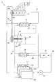
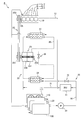
- FIG. 1 is a configuration diagram showing a heat exchange system according to the first embodiment of the present invention.
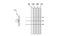
- FIG. 2A is a diagram showing an arrangement of radiators mounted on the hybrid vehicle.
- FIG. 2B is a diagram showing an example in which a Rankine cycle radiator is added to the radiator shown in FIG. 2A.
- FIG. 3 is a diagram showing the cooling capacity of a condenser sharing a radiator.
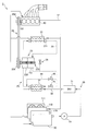
- FIG. 4 is a configuration diagram illustrating a heat exchange system according to the second embodiment.
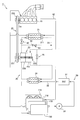
- FIG. 5 is a configuration diagram showing a heat exchange system according to the third embodiment.
- FIG. 6 is a configuration diagram showing a heat exchange system according to the fourth embodiment.
- FIG. 7 is a configuration diagram illustrating a heat exchange system according to the fifth embodiment.
- FIG. 8 is a configuration diagram illustrating a heat exchange system according to the sixth embodiment.
- FIG. 9 is a configuration diagram illustrating a heat exchange system according to the seventh embodiment.
- FIG. 1 is a diagram showing a heat exchange system according to the first embodiment of the present invention.
- the heat exchange system 1 is mounted on a hybrid vehicle that uses power from an engine and an electric motor.
- the heat exchange system 1 regenerates the waste heat energy of the engine 10 as power of the engine 10 using the Rankine cycle 20, and cools the inverter 31 using the cooling device 30.
- the heat exchange system 1 includes an engine 10, a cooling water passage 12, a heat exchanger 21, a refrigerant passage 22, a rotating machine 23, a condenser 24, a belt transmission mechanism 25, a cooling device 30, and a radiator 110. And a radiator fan 111.
- the rotating machine 23 includes an expander 231 and a refrigerant pump 232.
- the Rankine cycle 20 includes a heat exchanger 21 that recovers waste heat of the engine 10 into a refrigerant, an expander 231 that generates power using the refrigerant at the outlet 211 of the heat exchanger 21, and a refrigerant that has exited the expander 231.
- a condenser 24 for condensation is included in The Rankine cycle 20.
- the heat exchange system 1 uses the heat exchanger 21 to recover the waste heat of the engine 10 into the refrigerant of the Rankine cycle 20, and drives the expander 231 by expansion of the refrigerant.
- the driving force of the expander 231 is used as power for rotating the refrigerant pump 232 and is also used as power for assisting the engine 10 via the belt transmission mechanism 25.
- the refrigerant of Rankine cycle 20 is a working medium that operates expander 231.
- the heat exchanger 21 has a cooling water passage of the engine 10 and a refrigerant passage of the Rankine cycle 20.
- a cooling water passage 12 and a refrigerant passage 22 are connected to each passage of the heat exchanger 21.
- the heat exchanger 21 evaporates the refrigerant by using the waste heat of the engine 10 by flowing cooling water around the refrigerant passage and exchanging heat between the refrigerant and the cooling water.
- the engine 10 is a power source that drives the vehicle.
- the engine 10 burns gasoline and converts the combustion energy into rotational force of the crankshaft 101.
- the radiator fan 111 sends wind to the radiator 110 to cool the radiator 110.
- the radiator 110 cools the cooling water by the wind power of the radiator fan 111.
- the cooling water passage 12 includes a forward passage connecting the radiator 110 and the engine 10, a return passage connecting the engine 10 and the radiator 110, a branch passage branched from the return passage and connected to the inlet of the heat exchanger 21, and the heat exchanger 21. And a merging passage that merges from the exit to the outward path.
- the cooling water cooled by the radiator 110 circulates.
- the temperature rises to about 80 ° C. to 90 ° C.
- the refrigerant in the Rankine cycle 20 is vaporized and flows out from the heat exchanger 21 to the refrigerant passage 22.
- the refrigerant passage 22 includes a passage connecting the heat exchanger 21 and the expander 231, a passage connecting the expander 231 and the condenser 24, a passage connecting the condenser 24 and the refrigerant pump 232, and the refrigerant pump 232 and heat. And a passage connecting to the exchanger 21.
- the refrigerant passage 22 includes a bypass passage that branches from a passage connecting the heat exchanger 21 and the expander 231 and joins a passage connecting the expander 231 and the condenser 24.
- a bypass valve 26 is provided in the bypass passage. The bypass valve 26 opens when the amount of refrigerant flowing through the refrigerant passage 22 is not sufficient, for example, when the Rankine cycle 20 is started. Thereby, the starting time of Rankine cycle 20 is shortened.
- a temperature sensor, a pressure sensor, and the like provided in the refrigerant passage 22 are omitted.
- the expander 231 rotates the rotating shaft of the refrigerant pump 232 by expanding the refrigerant vaporized by the heat exchanger 21.
- the pulley 251 of the belt transmission mechanism 25 rotates to assist the engine 10. That is, the expander 231 generates a force that assists the engine 10 by expansion and contraction of the refrigerant.
- the expander 231 is a steam turbine.
- the condenser 24 cools and liquefies the refrigerant expanded by the expander 231.
- the refrigerant liquefied by the condenser 24 flows to the refrigerant pump 232.
- the refrigerant pump 232 is rotated by the driving force obtained by the expander 231 and supplies the refrigerant liquefied by the condenser 24 to the refrigerant passage of the heat exchanger 21.
- the rotation axis of the refrigerant pump 232 is coaxial with the expander 231 and the pulley 251.
- a clutch is provided between the rotation shafts of the refrigerant pump 232 and the pulley 251. When the clutch is in the disconnected state, the refrigerant pump 232 rotates together with the belt transmission mechanism 25 by the driving force of the expander 231.
- the refrigerant flowing through the refrigerant passage 22 is vaporized by the heat of the cooling water heated by the waste heat of the engine 10 when passing through the heat exchanger 21.
- the expander 231 expands the refrigerant and converts it into rotational energy.
- the pulley 252 of the belt transmission mechanism 25 is driven to assist the rotation of the crankshaft 101.
- the Rankine cycle radiator is arranged so as to overlap with the engine radiator or the like.
- the arrangement of the radiators mounted on the hybrid vehicle will be briefly described.
- FIG. 2A and FIG. 2B are diagrams showing a general radiator arrangement.
- FIG. 2A is a side view of the radiator mounted on the front end of the vehicle.
- FIG. 2B is a diagram showing an arrangement of each radiator when a radiator is used instead of the Rankine cycle condenser 24. 2A and 2B, the flow of wind from the radiator fan 111 is indicated by a solid line.
- the radiator 110 of the engine 10 As shown in FIG. 2A, the radiator 110 of the engine 10, the radiator 120 of the air conditioner, and the radiator 130 of the inverter 31 are arranged so as to overlap in the direction in which the wind of the radiator fan 111 flows.
- the radiator used as condenser 24 will be arranged on other radiators 110-130. For this reason, as the number of radiators increases, the cooling performance of each of the other radiators 110 to 130 decreases due to the Rankine cycle radiator.
- the refrigerant of the Rankine cycle is efficiently cooled using the radiator of the inverter.
- the condenser 24 shown in FIG. 1 cools the refrigerant of the Rankine cycle 20 using cooling water that cools the inverter 31.
- the cooling device 30 includes a condenser 24, an inverter 31, a cooling water passage 32, a circulation pump 33, and a radiator 130.
- the condenser 24 has a refrigerant passage through which the refrigerant from the expander 231 flows and a cooling water passage through which the cooling water from the inverter 31 flows.
- the condenser 24 is connected to the refrigerant passage 22 and the cooling water passage 32.
- the condenser 24 cools the refrigerant by exchanging heat between the refrigerant of the Rankine cycle 20 and the cooling water of the inverter 31.
- the heat of the refrigerant is radiated to the cooling water to cool the refrigerant, and the cooling water is warmed by the heat radiation from the refrigerant, and the raised cooling water flows to the radiator 130.
- the radiator 130 cools the cooling water by the wind power of the radiator fan 111.
- the circulation pump 33 supplies the cooling water cooled by the radiator 130 to the cooling water passage 32 of the inverter 31.
- the inverter 31 is provided in the cooling water passage 32 upstream of the condenser 24.
- the inverter 31 is a control device that controls the electric motor.
- the inverter 31 converts a DC voltage supplied from the battery into an AC voltage and supplies the AC voltage to the electric motor. As a result, the electric motor rotates to drive the hybrid vehicle.
- the cooling water supplied from the radiator 130 is caused to flow through the inverter 31 and the condenser 24, and the condenser 24 is cooled together with the inverter 31.
- coolant of Rankine cycle 20 which passes along the condenser 24 can be cooled.
- the inverter 31 is provided in the cooling water passage 32 upstream of the condenser 24, but may be provided in the cooling water passage 32 downstream of the condenser 24.
- FIG. 3 is a diagram showing a cooling capacity for cooling the refrigerant of the Rankine cycle 20 with the cooling water of the inverter 31.
- the vertical axis indicates the temperature of the cooling water at the inlet of the condenser 24, and the horizontal axis indicates the temperature of the outside air.
- the outside air temperature Y is an upper limit value of the outside air temperature at which the inverter 31 is used.
- the cooling water temperature region 311 indicates the temperature range of the cooling water that varies depending on the operation state of the inverter 31. As the load on the inverter 31 increases, the temperature of the cooling water at the inlet of the condenser 24 increases.
- the radiator 130 is designed so that the inverter 31 does not exceed the upper limit temperature Th, for example, 65 ° C. even when the load of the inverter 31 reaches the upper limit at the outside air temperature Y. For this reason, in the state where the outside air temperature is lower than the temperature Y or the load of the inverter 31 is low, the temperature of the cooling water passing through the inverter 31 is usually sufficiently lower than the upper limit temperature Th.
- the refrigerant can be cooled.
- the refrigerant cooling region 312 indicates a temperature range in which the refrigerant of the Rankine cycle 20 can be cooled with the cooling water of the radiator 130 according to the temperature of the outside air. That is, this is a region where the heat of the refrigerant in the Rankine cycle 20 can be cooled by the radiator 130. For example, when 30 ° C. cooling water flows in the condenser 24, the refrigerant in the Rankine cycle 20 is cooled to around 50 ° C.
- the radiator 130 can cool the refrigerant of the Rankine cycle 20 even when the outside air temperature is close to the temperature Y and the inverter 31 is in a high load state, that is, in a state where the temperature of the cooling water is high.
- the condenser 24 is cooled by the cooling water that cools the inverter 31.
- the condenser 24 cools the refrigerant in the Rankine cycle 20 by exchanging heat between the refrigerant that has left the expander 231 and the cooling water that circulates through the inverter 31.
- the coolant of the Rankine cycle 20 and the inverter 31 can be efficiently cooled together by the cooling water cooled by the radiator 130. For this reason, since it is not necessary to provide a new radiator to cool the refrigerant of the Rankine cycle 20, it is possible to reduce the number of radiators mounted on the hybrid vehicle and to reduce the cooling performance of the radiator mounted on the hybrid vehicle. Can be avoided.
- the inverter 31 is provided in the cooling water passage 32 upstream of the condenser 24.
- the bypass valve 26 fails and opens, the high-temperature refrigerant vaporized by the heat exchanger 21 flows directly into the condenser 24, but the inverter 31 is provided upstream of the condenser 24. Therefore, the cooling water overheated by the heat of the refrigerant does not flow to the inverter 31.
- the time until the cooling water supplied to the inverter 31 reaches the upper limit temperature can be delayed as the temperature of the cooling water rises due to overheating of the refrigerant. For this reason, it is possible to prevent the inverter 31 from overheating during the period from when the Rankine cycle failure is detected to when the Rankine cycle 20 is stopped.
- FIG. 4 is a diagram showing a heat exchange system 2 according to the second embodiment of the present invention.
- the heat exchange system 2 is provided with a bypass passage 41 of the condenser 24, an on-off valve 42, and an on-off valve 43 in the cooling device 30.
- a rotation speed sensor 233 is provided in the vicinity of the rotation shaft of the expander 231.
- the bypass passage 41 branches from the cooling water passage 32 upstream of the on-off valve 42 and joins the cooling water passage 32 downstream of the condenser 24.
- the on-off valve 42 and the on-off valve 43 switch whether the cooling water from the inverter 31 flows into the condenser 24 or the bypass passage 41.
- the on-off valve 42 and the on-off valve 43 are controlled by an unshown ECU (Electronic Control Unit).
- the on-off valve 42 is provided in the cooling water passage 32 upstream of the condenser 24.
- the on-off valve 42 opens and closes under the control of the ECU, and shuts off the cooling water flowing through the condenser 24.
- the on-off valve 43 is provided in the bypass passage 41.
- the on-off valve 43 opens and closes under the control of the ECU, and allows cooling water to flow through the bypass passage 41.
- the on-off valve 43 opens when the on-off valve 42 is closed, and closes when the on-off valve 42 is open.
- the on-off valve 42 and the on-off valve 43 are switched when the Rankine cycle 20 fails. For example, when a clutch provided in the rotating machine 23 breaks down and high-temperature refrigerant flows from the expander 231 to the condenser 24, and the inverter 31 may reach the upper limit temperature due to heat dissipation of the refrigerant in the condenser 24.
- the on-off valve 42 and the on-off valve 43 are switched.
- the ECU closes the on-off valve 42 when the rotational speed sensor 233 detects that the expander 231 is rotating. Open the on-off valve 43.
- the ECU determines that the Rankine cycle 20 is abnormal and switches the on-off valve 42 and on-off valve 43.
- the cooling water that has flowed to the condenser 24 flows to the bypass passage 41, so that the cooling water can be prevented from being overheated by the condenser 24. Therefore, it can be avoided that the cooling water rises to a dangerous temperature due to overheating from the refrigerant to the cooling water, and the inverter 31 is overheated. That is, it is possible to eliminate the adverse effects that occur in the inverter 31 due to sharing of the radiator 130.
- the bypass passage 41 in the cooling water passage 32 even if a high-temperature refrigerant is supplied to the condenser 24 when the Rankine cycle 20 is abnormal, the refrigerant is supplied to the cooling water. The temperature rise of the cooling water due to overheating can be suppressed.
- the on-off valve 43 when the on-off valve 42 is opened, the on-off valve 43 is closed, and when the on-off valve 42 is closed, the on-off valve 43 is opened so that the cooling water flows into the condenser 24 or into the bypass passage 41. Switch between flowing.
- the cooling water can be passed only through either the condenser 24 or the bypass passage 41.
- the cooling water flows only through the condenser 24, so that the refrigerant can be efficiently cooled.
- the cooling water flows only in the bypass passage 41, so that it is possible to reliably prevent the cooling water from being overheated by the heat of the refrigerant. That is, the inverter 31 can be reliably protected while efficiently cooling the refrigerant of the Rankine cycle 20.
- the on-off valve 42 and the on-off valve 43 are provided in the cooling water passage 32 to switch the flow direction of the cooling water, but a three-way valve may be provided in a portion where the bypass passage 41 branches from the cooling water passage 32. .
- the cooling water passage can be switched from the cooling water passage 32 to the bypass passage 41 by providing only one valve, so that the cooling device 30 can have a simple configuration.
- FIG. 5 is a diagram showing a heat exchange system 3 according to the third embodiment of the present invention.
- the heat exchange system 3 includes a bypass passage 44, an on-off valve 45, and an on-off valve 46 in the refrigerant passage 22 instead of the bypass passage 41 of the heat exchange system 2.
- Other configurations are the same as those of the heat exchange system 2.
- the bypass passage 44 branches from the refrigerant passage 22 upstream of the on-off valve 45 and joins the refrigerant passage 22 downstream of the condenser 24.
- the on-off valve 45 and the on-off valve 46 switch whether the refrigerant from the expander 231 flows into the condenser 24 or the bypass passage 44.
- the on-off valve 45 and the on-off valve 46 are controlled by the ECU.
- the on-off valve 45 is provided in the refrigerant passage 22 upstream of the condenser 24.
- the on-off valve 45 opens and closes under the control of the ECU, and blocks the refrigerant flowing through the condenser 24.
- the on-off valve 46 is provided in the bypass passage 44.
- the on-off valve 46 opens and closes under the control of the ECU, and causes the refrigerant to flow through the bypass passage 44.
- the on-off valve 46 opens when the on-off valve 45 is closed, and closes when the on-off valve 45 is open.
- the ECU determines that the Rankine cycle 20 is abnormal and opens the on-off valve 45. Close and open the on-off valve 46. Thereby, since the refrigerant from the expander 231 does not flow to the condenser 24, it is possible to prevent the cooling water flowing through the inverter 31 from being overheated by the heat of the refrigerant in the Rankine cycle.
- the supply of the high-temperature refrigerant to the condenser 24 can be stopped when the Rankine cycle 20 is abnormal. Thereby, the temperature increase of the cooling water by the overheating from a refrigerant
- the refrigerant can be passed through only one of the condenser 24 and the bypass passage 44. For this reason, since the refrigerant flows only into the condenser 24 when the Rankine cycle 20 is normal, the refrigerant can be cooled efficiently. On the other hand, when the Rankine cycle 20 is abnormal, the refrigerant flows only in the bypass passage 44, so that it is possible to reliably prevent the cooling water from being overheated by the heat of the refrigerant.
- the on-off valve 42 and the on-off valve 43 do not break down and interrupt the circulation of the cooling water. For this reason, the risk that the electric motor which is a power source of the hybrid vehicle stops due to overheating of the inverter 31 can be reduced.
- the on-off valve 45 and the on-off valve 46 are provided in the refrigerant passage 22 to switch the flow direction of the refrigerant.
- a three-way valve may be provided at a portion where the bypass passage 44 branches from the refrigerant passage 22.
- the cooling device 30 can have a simple configuration.
- supply of the refrigerant to the condenser 24 is stopped when the Rankine cycle 20 fails to avoid overheating of the cooling water.
- the refrigerant is not supplied to the heat exchanger 21 but the condenser 24. Supply may be stopped.
- FIG. 6 is a diagram showing a heat exchange system 4 according to the fourth embodiment of the present invention.
- the heat exchange system 4 includes a bypass passage 51, an on-off valve 52, and an on-off valve 53 in the refrigerant passage 22 instead of the bypass passage 44 of the heat exchange system 3.
- Other configurations are the same as those of the heat exchange system 3.
- the bypass passage 51 branches from the refrigerant passage 22 upstream of the on-off valve 52 and joins the refrigerant passage 22 downstream of the heat exchanger 21.
- the on-off valve 52 and the on-off valve 53 switch whether the refrigerant from the refrigerant pump 232 flows into the heat exchanger 21 or the bypass passage 51.
- the on-off valve 52 and the on-off valve 53 are controlled by the ECU.
- a three-way valve may be provided at a portion where the bypass passage 51 branches from the refrigerant passage 22 in order to simplify the configuration.
- the on-off valve 52 is provided in the refrigerant passage 22 upstream of the heat exchanger 21.
- the on-off valve 52 is opened and closed under the control of the ECU, and blocks the refrigerant flowing through the heat exchanger 21.
- the on-off valve 53 is provided in the bypass passage 51.
- the on-off valve 53 opens and closes under the control of the ECU, and causes the refrigerant to flow through the bypass passage 51.
- the on-off valve 53 opens when the on-off valve 52 is closed, and closes when the on-off valve 52 is open.
- the ECU determines that the Rankine cycle 20 is abnormal, and the open / close valve 52 is closed and the on-off valve 53 is opened.
- the refrigerant flowing through the heat exchanger 21 is blocked, the refrigerant is supplied to the condenser 24 via the expander 231 without being heated by the heat exchanger 21. For this reason, it is possible to prevent the cooling water of the inverter 31 from being heated by the refrigerant flowing through the condenser 24.
- the bypass passage 51 in the refrigerant passage 22 it is possible to reduce the heat radiation of the refrigerant in the heat exchanger 21 when the Rankine cycle 20 is abnormal.
- the temperature rise of the cooling water by the heat radiation from the refrigerant of the Rankine cycle 20 to the cooling water of the inverter 31 can be suppressed.
- an electronic device or the like provided in the vicinity of the refrigerant passage 22 is prevented from being damaged by the heat of the refrigerant. be able to.
- the on-off valve 53 is closed when the on-off valve 52 is opened, and the on-off valve 53 is opened when the on-off valve 52 is closed, so that the refrigerant from the refrigerant pump 232 flows to the heat exchanger 21. Switching to the bypass passage 51.
- the refrigerant can be passed only through either the heat exchanger 21 or the bypass passage 51.
- the refrigerant flows only through the heat exchanger 21, so that the refrigerant can be efficiently vaporized.
- the refrigerant flows only in the bypass passage 51, so that the heat exchanger 21 can reliably prevent the refrigerant from being heated.
- FIG. 7 is a diagram showing a heat exchange system 5 according to the fifth embodiment of the present invention.
- the heat exchange system 5 includes a bypass passage 54, an on-off valve 55, and an on-off valve 56 in the cooling water passage 12 instead of the bypass passage 51 of the heat exchange system 4.
- Other configurations are the same as those of the heat exchange system 4.
- the bypass passage 54 branches from the cooling water passage 12 upstream of the on-off valve 55 and joins the cooling water passage 12 downstream of the heat exchanger 21.
- the on-off valve 55 and the on-off valve 56 switch whether the coolant from the engine 10 flows into the heat exchanger 21 or the bypass passage 54.
- the on-off valve 55 and the on-off valve 56 are controlled by the ECU.
- a three-way valve may be provided at a portion where the bypass passage 54 branches from the cooling water passage 12 in order to simplify the configuration.
- the on-off valve 55 is provided in the cooling water passage 12 upstream of the heat exchanger 21.
- the on-off valve 55 opens and closes under the control of the ECU, and shuts off the cooling water flowing to the heat exchanger 21.
- the on-off valve 56 is provided in the bypass passage 54.
- the on-off valve 56 opens and closes under the control of the ECU, and allows cooling water to flow through the bypass passage 54.
- the on-off valve 56 opens when the on-off valve 55 is closed, and closes when the on-off valve 55 is open.
- the ECU determines that the Rankine cycle 20 is abnormal and closes the on-off valve 55. Then, the on-off valve 56 is opened.
- the cooling water heated by the engine 10 does not flow to the heat exchanger 21, so that the refrigerant in the Rankine cycle 20 is not heated by the heat exchanger 21. Therefore, since the refrigerant that is not heated from the heat exchanger 21 flows to the condenser 24 via the expander 231, it is possible to prevent the cooling water of the inverter 31 from being overheated by the heat of the refrigerant.
- the bypass passage 54 in the cooling water passage 12 when the Rankine cycle 20 is abnormal, it becomes difficult for the cooling water heated by the engine 10 to flow into the heat exchanger 21. Can be suppressed.
- the condenser 24 the temperature rise of the cooling water due to the heat radiation from the refrigerant to the cooling water of the inverter 31 can be suppressed. Furthermore, since the low-temperature refrigerant circulates through the refrigerant passage 22, it is possible to prevent the electronic device or the like provided in the vicinity of the refrigerant passage 22 from being damaged by the heat of the refrigerant.
- the on-off valve 56 is closed when the on-off valve 55 is opened, and the on-off valve 56 is opened when the on-off valve 55 is closed, so that the cooling water from the engine 10 flows into the heat exchanger 21. Switching to the bypass passage 54.
- the cooling water can be passed only through either the heat exchanger 21 or the bypass passage 54. Therefore, when the Rankine cycle 20 is normal, the cooling water can be flowed only to the heat exchanger 21, so that the refrigerant can be efficiently vaporized.
- the refrigerant is allowed to flow only through the bypass passage 54 and the cooling water heated by the engine 10 is not allowed to flow into the heat exchanger 21, thereby reliably preventing the refrigerant from being heated in the heat exchanger 21. be able to.
- FIG. 8 is a diagram showing a heat exchange system 6 according to the sixth embodiment of the present invention.
- the heat exchange system 6 includes a bypass passage 71 and an on-off valve 72 in the cooling water passage 32 instead of the bypass passage 54 of the heat exchange system 5.
- Other configurations are the same as those of the heat exchange system 5.
- the bypass passage 71 branches from the cooling water passage 32 upstream of the on-off valve 72 and joins the cooling water passage 32 downstream of the condenser 24.
- An inverter 31 is provided in the bypass passage 71.
- the on-off valve 72 is a cooling water passage 32 parallel to the bypass passage 71 and is provided in the cooling water passage 32 upstream of the condenser 24.
- the on-off valve 72 switches whether the cooling water from the radiator 130 flows to the condenser 24 or the bypass passage 71.
- the on-off valve 72 is controlled by the ECU.
- the on-off valve 72 is closed so that the cooling water does not flow into the cooling water passage 32 when the Rankine cycle 20 fails.
- the ECU normally opens the on-off valve 72 and closes the on-off valve 72 when an abnormality in the Rankine cycle 20 is detected.
- the refrigerant that has been overheated due to the abnormality of the Rankine cycle 20 flows to the condenser 24, the cooling water that has flowed to the condenser 24 is shut off. It is possible to prevent the cooling water 31 from being overheated.
- the bypass passage 71 is provided in the cooling water passage 32. Therefore, since cooling water is distributed to the condenser 24 and the bypass passage 71 provided in parallel, the heat dissipation efficiency to the whole cooling water by the condenser 24 is lowered. For this reason, the temperature rise of the cooling water can be suppressed when the Rankine cycle 20 is abnormal.
- the inverter 31 is provided in the bypass passage 71. Thereby, even when the cooling water is overheated by the condenser 24, the cooling water cooled by the radiator 130 is directly distributed also to the cooling water passage of the inverter 31, so that the inverter 31 can be protected.
- an on-off valve 72 is provided in the cooling water passage 32 parallel to the bypass passage 71.
- the on-off valve 72 is closed so that the cooling water does not flow into the cooling water passage 32 when the Rankine cycle 20 fails.
- the on-off valve 72 is open when the Rankine cycle 20 is normal, the refrigerant in the Rankine cycle 20 can be cooled while the inverter 31 is cooled.
- the on-off valve 72 is closed, so that the cooling water to the condenser 24 can be shut off to prevent overheating of the cooling water by the refrigerant in the Rankine cycle 20.
- only one on-off valve 72 is provided in the bypass passage 71 in order to shut off the cooling water flowing through the condenser 24 while cooling the inverter 31, so that the cooling device 30 can be simplified. Can be configured.
- FIG. 9 is a diagram showing a heat exchange system 7 according to the seventh embodiment of the present invention.
- the heat exchange system 7 includes a bypass passage 73 and an on-off valve 74 in the refrigerant passage 22 instead of the on-off valve 72 of the heat exchange system 6.
- Other configurations are the same as those of the heat exchange system 6.
- the bypass passage 73 branches from the refrigerant passage 22 upstream from the condenser 24 and joins the refrigerant passage 22 downstream from the condenser 24.
- the on-off valve 74 is provided in the bypass passage 73.
- the on-off valve 74 switches whether the refrigerant from the expander 231 flows to the condenser 24 or the bypass passage 73.
- the on-off valve 74 is controlled by the ECU.
- ECU opens the on-off valve 74 and closes the on-off valve 74 when an abnormality of the Rankine cycle 20 is detected.
- the refrigerant that has flowed into the condenser 24 by the on-off valve 74 flows into the bypass passage 73, so that the cooling water in the condenser 24 The temperature rise due to overheating of can be reduced.
- the bypass passage 73 is provided in the refrigerant passage 22. This makes it difficult for the high-temperature refrigerant to flow into the condenser 24 when the Rankine cycle is abnormal. For this reason, the temperature rise of the cooling water distributed to the condenser 24 can be suppressed, and the temperature rise of the cooling water supplied to the inverter 31 can be suppressed.
- an on-off valve 74 is provided in the bypass passage 73.
- the on-off valve 74 switches whether the refrigerant supplied from the expander 231 flows to the condenser 24 or the bypass passage 73.
- the refrigerant flowing through the condenser 24 can be effectively blocked only by providing one on-off valve 74 in the bypass passage 71.
Landscapes
- Engineering & Computer Science (AREA)
- Chemical & Material Sciences (AREA)
- Combustion & Propulsion (AREA)
- Mechanical Engineering (AREA)
- General Engineering & Computer Science (AREA)
- Automation & Control Theory (AREA)
- Transportation (AREA)
- Physics & Mathematics (AREA)
- Thermal Sciences (AREA)
- Engine Equipment That Uses Special Cycles (AREA)
- Hybrid Electric Vehicles (AREA)
Abstract
熱交換システムは、エンジン及び電動機の動力を用いるハイブリッド車両に搭載される。熱交換システムは、エンジンの廃熱を冷媒に回収する熱交換器、この熱交換器出口の冷媒を用いて動力を発生させる膨張機、この膨張機を出た冷媒を凝縮させる凝縮器を含むランキンサイクルを備える。そして熱交換システムは、電動機を制御する制御装置と、制御装置を冷却する冷却水が流れる冷却水通路とを備え、制御装置を冷却する冷却水により凝縮器を冷却する。
Description
この発明は、ハイブリッド車両に搭載される熱交換システムに関する。
ランキンサイクルによって車両の廃熱を利用して動力を得るシステムが提案されている。ランキンサイクルとエアコンサイクルとを有する車両においては、通常、ランキン用のコンデンサーと、エアコン用のコンデンサーとが、車両のフロントエンド部分に配置される(JP2011-84102A参照)。
しかしながら、前述したランキンサイクルを有する車両では、ランキン用のコンデンサーをフロントエンドに設ける必要があるため、エアコン用のコンデンサーの設置スペースが制限されることになる。このため、他のコンデンサーの冷却性能が低下してしまい、効率的にランキンサイクルの作動媒体を冷却する構成になっていなかった。
本発明は、このような問題点に着目してなされた。本発明の目的は、効率的にランキンサイクルの作動媒体を冷却することにある。
本発明による熱交換システムのひとつの態様は、エンジン及び電動機の動力を用いるハイブリッド車両に搭載される熱交換システムである。この熱交換システムは、エンジンの廃熱を冷媒に回収する熱交換器、この熱交換器出口の冷媒を用いて動力を発生させる膨張機、この膨張機を出た冷媒を凝縮させる凝縮器を含むランキンサイクルを有する。そして熱交換システムは、電動機を制御する制御装置と、制御装置を冷却する冷却水が流れる冷却水通路とを備え、制御装置を冷却する冷却水により凝縮器を冷却することを特徴とする。
以下、添付図面を参照しながら本発明の実施形態について説明する。
(第1実施形態)
図1は、本発明の第1実施形態に係る熱交換システムを示す図である。
図1は、本発明の第1実施形態に係る熱交換システムを示す図である。
熱交換システム1は、エンジン及び電動機の動力を用いるハイブリッド車両に搭載される。熱交換システム1は、ランキンサイクル20を利用してエンジン10の廃熱エネルギーをエンジン10の動力として回生するするとともに、冷却装置30を用いてインバーター31を冷却する。
熱交換システム1は、エンジン10と、冷却水通路12と、熱交換器21と、冷媒通路22と、回転機23と、凝縮器24と、ベルト伝達機構25と、冷却装置30と、ラジエーター110と、ラジエーターファン111と、を含む。回転機23は、膨張機231と冷媒ポンプ232とを含む。
ランキンサイクル20は、エンジン10の廃熱を冷媒に回収する熱交換器21と、熱交換器21の出口211の冷媒を用いて動力を発生させる膨張機231と、膨張機231を出た冷媒を凝縮させる凝縮器24と、を含む。
熱交換システム1は、熱交換器21を用いてエンジン10の廃熱をランキンサイクル20の冷媒に回収し、冷媒の膨張によって膨張機231を駆動させる。膨張機231の駆動力は、冷媒ポンプ232を回転させる動力として用いられると共に、ベルト伝達機構25を介してエンジン10をアシストする動力としても利用される。なお、ランキンサイクル20の冷媒とは、膨張機231を作動する作動媒体のことである。
熱交換器21は、エンジン10の冷却水通路と、ランキンサイクル20の冷媒通路と、を有する。熱交換器21のそれぞれの通路には、冷却水通路12及び冷媒通路22が接続される。熱交換器21では、冷媒通路のまわりに冷却水を流して冷媒と冷却水との間で熱交換させることによりエンジン10の廃熱を利用して冷媒を蒸発させる。
エンジン10は、車両を駆動する動力源である。エンジン10は、ガソリンを燃焼させてその燃焼エネルギーをクランクシャフト101の回転力に変換する。
ラジエーターファン111は、ラジエーター110へ風を送り、ラジエーター110を冷やす。
ラジエーター110は、ラジエーターファン111の風力によって冷却水を冷やす。
冷却水通路12は、ラジエーター110とエンジン10とを結ぶ往路と、エンジン10とラジエーター110とを結ぶ復路と、復路から分岐して熱交換器21の入口に接続した分岐通路と、熱交換器21の出口から往路に合流する合流通路と、を含む。
冷却水通路12では、ラジエーター110で冷やされた冷却水が循環する。冷却水は、エンジン10を通ると80℃~90℃程度まで昇温する。昇温した冷却水が熱交換器21を通ることで、ランキンサイクル20の冷媒が気化して熱交換器21から冷媒通路22へ流れ出る。
冷媒通路22は、熱交換器21と膨張機231とを結ぶ通路と、膨張機231と凝縮器24とを結ぶ通路と、凝縮器24と冷媒ポンプ232とを結ぶ通路と、冷媒ポンプ232と熱交換器21とを結ぶ通路と、を含む。
また、冷媒通路22は、熱交換器21と膨張機231とを結ぶ通路から分岐して、膨張機231と凝縮器24とを結ぶ通路に合流するバイパス通路を含む。バイパス通路にはバイパス弁26が設けられる。バイパス弁26は、ランキンサイクル20の始動時等に冷媒通路22を流れる冷媒の量が十分でないときに開弁する。これにより、ランキンサイクル20の起動時間を短縮する。なお、本実施形態では、説明の便宜上、冷媒通路22に設けられている温度センサーや圧力センサー等を省略している。
膨張機231は、熱交換器21で気化した冷媒を膨張させることで、冷媒ポンプ232の回転軸を回転させる。これにより、ベルト伝達機構25のプーリー251が回転してエンジン10をアシストする。すなわち、膨張機231は、冷媒の膨張収縮によってエンジン10をアシストする力を発生する。膨張機231は、蒸気タービンである。
凝縮器24は、膨張機231で膨張した冷媒を冷却して液化する。凝縮器24で液化した冷媒は、冷媒ポンプ232に流れる。
冷媒ポンプ232は、膨張機231で得られた駆動力によって回転し、凝縮器24で液化した冷媒を熱交換器21の冷媒通路に供給する。冷媒ポンプ232の回転軸は、膨張機231とプーリー251と同軸である。冷媒ポンプ232とプーリー251の回転軸の間にはクラッチが設けられている。クラッチが切断状態であるときは、冷媒ポンプ232は、膨張機231の駆動力によってベルト伝達機構25と共に回転する。
このようにランキンサイクル20では、冷媒通路22を流れる冷媒は、熱交換器21を通るとエンジン10の廃熱で昇温した冷却水の熱によって気化する。気化した冷媒が膨張機231に入ると、膨張機231で冷媒が膨張され回転エネルギーに変換される。膨張機231が回転することで、ベルト伝達機構25のプーリー252が駆動してクランクシャフト101の回転がアシストされる。
このようなランキンサイクルでは、一般的に、凝縮器にラジエーターが使用されるため、ランキンサイクルのラジエーターは、エンジンのラジエーター等と重ねて配置される。ここで、ハイブリッド車両に搭載されるラジエーターの配列について簡単に説明する。
図2A及び図2Bは、一般的なラジエーターの配列を示す図である。図2Aは、車両のフロントエンドに搭載されているラジエーターを横から見た図である。図2Bは、ランキンサイクルの凝縮器24の代わりにラジエーターを使用した場合の各ラジエーターの配列を示す図である。図2A及び図2Bには、ラジエーターファン111からの風の流れが実線で示されている。
図2Aに示すように、ラジエーターファン111の風が流れる方向に、エンジン10のラジエーター110と、エアコンのラジエーター120と、インバーター31のラジエーター130と、が重ねて配置される。
そしてランキンサイクル20を利用する車両では、図2Bに示すように、凝縮器24として使用されるラジエーターを他のラジエーター110乃至130に重ねて配置することになる。このため、ラジエーターの数が増えると共に、ランキンサイクルのラジエーターによって他のラジエーター110乃至130のそれぞれの冷却性能が低下してしまう。
そこで、本発明の実施形態では、インバーターのラジエーターを利用してランキンサイクルの冷媒を効率的に冷却する。
第1実施形態では、図1に示した凝縮器24が、ランキンサイクル20の冷媒を、インバーター31を冷却する冷却水を利用して冷却する。
冷却装置30は、凝縮器24と、インバーター31と、冷却水通路32と、循環ポンプ33と、ラジエーター130と、を含む。
凝縮器24は、膨張機231からの冷媒が流れる冷媒通路と、インバーター31からの冷却水が流れる冷却水通路と、を有する。凝縮器24は、冷媒通路22と冷却水通路32とがそれぞれ接続される。凝縮器24は、ランキンサイクル20の冷媒とインバーター31の冷却水との間で熱交換させて冷媒を冷却する。凝縮器24では、冷媒の熱が冷却水に放熱されて冷媒が冷やされると共に、冷媒からの放熱によって冷却水が暖められ、昇温した冷却水がラジエーター130へ流れる。
ラジエーター130は、ラジエーターファン111の風力によって冷却水を冷やす。
循環ポンプ33は、ラジエーター130で冷やされた冷却水をインバーター31の冷却水通路32に供給する。
インバーター31は、凝縮器24よりも上流の冷却水通路32に設けられる。インバーター31は、電動機を制御する制御装置である。インバーター31は、バッテリーから供給される直流電圧を交流電圧に変換してその交流電圧を電動機に供給する。これにより、電動機が回転してハイブリッド車両を駆動する。
このように冷却装置30では、ラジエーター130から供給される冷却水をインバーター31と凝縮器24とに流して、インバーター31と共に凝縮器24を冷却する。これにより、凝縮器24を通るランキンサイクル20の冷媒を冷却することができる。なお、インバーター31は、凝縮器24よりも上流の冷却水通路32に設けているが、凝縮器24よりも下流の冷却水通路32に設けてもよい。
次に、ラジエーター130を利用した凝縮器24の冷却性能について説明する。
図3は、インバーター31の冷却水によってランキンサイクル20の冷媒を冷却する冷却能力を示す図である。図3では、縦軸が凝縮器24の入口での冷却水の温度を示し、横軸が外気の温度を示す。外気温度Yは、インバーター31が使用される外気温の上限値である。
冷却水温度領域311は、インバーター31の動作状態によって変化する冷却水の温度範囲を示す。インバーター31の負荷が高くなるほど、凝縮器24の入口の冷却水の温度は高くなる。
ラジエーター130は、外気温度Yにおいてインバーター31の負荷が上限に達したときであっても、インバーター31が上限温度Th、例えば65℃を超えないように設計されている。このため、外気温が温度Yよりも低い状態や、インバーター31の負荷が低い状態では、インバーター31を通過する冷却水の温度は、通常、上限温度Thよりも十分に低いため、ランキンサイクル20の冷媒を冷やすことができる。
冷媒冷却領域312は、外気の温度に応じて、ラジエーター130の冷却水でランキンサイクル20の冷媒を冷却できる温度範囲を示す。すなわち、ランキンサイクル20の冷媒の熱をラジエーター130で冷却できる領域である。例えば、凝縮器24では30℃の冷却水が流れると、ランキンサイクル20の冷媒は50℃前後まで冷やされる。
このように、ラジエーター130は、温度Yに近い外気温で、かつ、インバーター31が高負荷の状態、すなわち冷却水の温度が高い状態でも、ランキンサイクル20の冷媒を冷却することが可能である。
本発明の第1実施形態によれば、インバーター31を冷却する冷却水によって凝縮器24を冷却する。そして凝縮器24は、膨張機231を出た冷媒と、インバーター31を循環する冷却水との間で熱交換させることにより、ランキンサイクル20の冷媒を冷却する。
これにより、ラジエーター130で冷やされた冷却水によって、ランキンサイクル20の冷媒とインバーター31とをまとめて効率的に冷却することが可能となる。このため、ランキンサイクル20の冷媒を冷却するために新たにラジエーターを設ける必要がないので、ハイブリッド車両に搭載されるラジエーターの数を削減できると共に、ハイブリッド車両に搭載されるラジエーターの冷却性能の低下を回避できる。
また、本実施形態では、インバーター31は凝縮器24よりも上流の冷却水通路32に設けられる。万一、バイパス弁26が故障して開弁したときには熱交換器21で気化した高温の冷媒が直接、凝縮器24に流れてしまうが、凝縮器24よりも上流にインバーター31が設けられているため、冷媒の熱によって過熱された冷却水がインバーター31に流れることはない。
したがって、冷媒の過熱による冷却水の温度上昇に伴い、インバーター31に供給される冷却水が上限温度に達するまでの時間を遅らせることができる。このため、ランキンサイクルの故障を検出してからランキンサイクル20を停止するまでの期間に、インバーター31がオーバーヒートすることを防ぐことができる。
また、プーリー251と冷媒ポンプ232との間に設けられたクラッチが故障したときにも、高温の冷媒が凝縮器24に流れ続けてラジエーター130の冷却能力を超えてしまう場合がある。このような場合には、インバーター31がオーバーヒートしてしまい、ハイブリッド走行ができなくなることが懸念される。そこで、ランキンサイクルの故障に伴うインバーター31のオーバーヒートをより確実に防ぐ手法について、以下に図面を参照して説明する。
(第2実施形態)
図4は、本発明の第2実施形態に係る熱交換システム2を示す図である。
図4は、本発明の第2実施形態に係る熱交換システム2を示す図である。
熱交換システム2は、図1に示した熱交換システム1に加えて、冷却装置30に凝縮器24のバイパス通路41と開閉弁42と開閉弁43とを備える。また、膨張機231の回転軸の近傍に、回転速度センサー233が設けられている。なお、他の構成については、熱交換システム1と同じであるため、以下同じ符号を付してここでの説明を省略する。
バイパス通路41は、開閉弁42よりも上流の冷却水通路32から分岐し、凝縮器24よりも下流の冷却水通路32に合流する。
開閉弁42及び開閉弁43は、インバーター31からの冷却水が凝縮器24に流れるか、バイパス通路41に流れるかを切り替える。開閉弁42及び開閉弁43は、不図示のECU(電子制御ユニット:Electronic Control Unit)によって制御される。
開閉弁42は、凝縮器24よりも上流の冷却水通路32に設けられる。開閉弁42は、ECUの制御によって開閉し、凝縮器24に流れる冷却水を遮断する。
開閉弁43は、バイパス通路41に設けられる。開閉弁43は、ECUの制御によって開閉し、バイパス通路41に冷却水を流す。開閉弁43は、開閉弁42が閉じているときに開き、開閉弁42が開いているときに閉じる。
開閉弁42及び開閉弁43は、ランキンサイクル20の故障時に切り替えられる。例えば、回転機23に設けられたクラッチが故障して膨張機231から高温の冷媒が凝縮器24に流れ、凝縮器24での冷媒の放熱によってインバーター31が上限温度に達する可能性があるときに、開閉弁42及び開閉弁43が切り替えられる。
具体的には、ランキンサイクル20の運転を停止して高速走行しているときに、ECUが、回転速度センサー233によって膨張機231が回転していることを検出した場合に、開閉弁42を閉じて開閉弁43を開く。あるいは、ECUは、冷媒通路22に設けられた温度センサーの信号が予め定められた温度閾値を超えたときに、ランキンサイクル20の異常と判定して開閉弁42及び開閉弁43を切り替える。
開閉弁42及び開閉弁43の切替えによって、凝縮器24に流れていた冷却水はバイパス通路41に流れることになるため、冷却水が凝縮器24で過熱されることを防ぐことができる。したがって、冷媒から冷却水への過熱によって冷却水が危険温度まで上昇し、インバーター31がオーバーヒートしてしまうことを回避できる。すなわち、ラジエーター130を共用することに伴うインバーター31に生じる弊害を排除することができる。
第2実施形態によれば、冷却水通路32にバイパス通路41を設けることで、ランキンサイクル20の異常時に凝縮器24に高温の冷媒が供給されることになっても、冷媒から冷却水への過熱による冷却水の温度上昇を抑制することができる。
また、本実施形態では、開閉弁42を開いたときに開閉弁43を閉じ、開閉弁42を閉じたときに開閉弁43を開くことで、冷却水が凝縮器24に流れるかバイパス通路41に流れるかを切り替える。
このため、凝縮器24又はバイパス通路41のいずれか一方にのみ冷却水を通すことができる。これにより、ランキンサイクル20の正常時には、凝縮器24にのみ冷却水が流れるので冷媒を効率良く冷やすことができる。
一方、ランキンサイクル20の異常時には、バイパス通路41にのみ冷却水が流れるので、冷媒の熱によって冷却水が過熱されることを確実に防ぐことができる。すなわち、ランキンサイクル20の冷媒を効率良く冷却しつつ、インバーター31を確実に保護することができる。
本実施形態では、開閉弁42及び開閉弁43を冷却水通路32に設けて冷却水の流れ方向を切り替えたが、バイパス通路41が冷却水通路32から分岐する部分に三方弁を設けてもよい。この場合には、1つの弁を設けるだけで、冷却水の流路を冷却水通路32からバイパス通路41に切り替えが可能となるので、冷却装置30を簡易な構成にすることができる。次に、凝縮器24をバイパスするためにバイパス通路を冷媒通路22に設ける例について説明する。
(第3実施形態)
図5は、本発明の第3実施形態に係る熱交換システム3を示す図である。
図5は、本発明の第3実施形態に係る熱交換システム3を示す図である。
熱交換システム3は、熱交換システム2のバイパス通路41に代えて、冷媒通路22にバイパス通路44と開閉弁45と開閉弁46とを備える。他の構成については、熱交換システム2と同じである。
バイパス通路44は、開閉弁45よりも上流の冷媒通路22から分岐し、凝縮器24よりも下流の冷媒通路22に合流する。
開閉弁45及び開閉弁46は、膨張機231からの冷媒が、凝縮器24に流れるかバイパス通路44に流れるかを切り替える。開閉弁45及び開閉弁46は、ECUによって制御される。
開閉弁45は、凝縮器24よりも上流の冷媒通路22に設けられる。開閉弁45は、ECUの制御によって開閉し、凝縮器24に流れる冷媒を遮断する。
開閉弁46は、バイパス通路44に設けられる。開閉弁46は、ECUの制御によって開閉し、バイパス通路44に冷媒を流す。開閉弁46は、開閉弁45が閉じているときに開き、開閉弁45が開いているときに閉じる。
第2実施形態と同様、ランキンサイクル20の停止中に、万一、回転速度センサー233で膨張機231の回転が検出されたときには、ECUは、ランキンサイクル20の異常と判定し、開閉弁45を閉じ、開閉弁46を開く。これにより、膨張機231からの冷媒が凝縮器24に流れなくなるので、インバーター31を流れる冷却水がランキンサイクルの冷媒の熱によって過熱されることを防ぐことができる。
第3実施形態によれば、冷媒通路22にバイパス通路44を設けることで、ランキンサイクル20の異常時に凝縮器24への高温の冷媒の供給を停止することができる。これにより、凝縮器24において冷媒から冷却水への過熱による冷却水の温度上昇を防止することができる。
また、本実施形態では、開閉弁45を開いたときに開閉弁46を閉じ、開閉弁45を閉じたときに開閉弁46を開くことで、膨張機231からの冷媒が凝縮器24に流れるかバイパス通路44に流れるかを切り替える。
これにより、凝縮器24又はバイパス通路44のいずれか一方にのみ冷媒を通すことができる。このため、ランキンサイクル20の正常時には、凝縮器24にのみ冷媒が流れるので、冷媒を効率良く冷やすことができる。一方、ランキンサイクル20の異常時には、バイパス通路44にのみ冷媒が流れるので、冷媒の熱によって冷却水が過熱されることを確実に防ぐことができる。
さらに、第2実施形態と異なり、開閉弁42及び開閉弁43が故障して冷却水の循環を遮断してしまうことがない。このため、インバーター31のオーバーヒートが原因でハイブリッド車両の動力源である電動機が停止するというリスクを低減することができる。
また、本実施形態では、開閉弁45及び開閉弁46を冷媒通路22に設けて冷媒の流れ方向を切り替えたが、バイパス通路44が冷媒通路22から分岐する部分に三方弁を設けてもよい。この場合には冷却装置30を簡易な構成にすることができる。
なお、第3実施形態では、ランキンサイクル20の故障時に凝縮器24への冷媒の供給を停止して冷却水の過熱を回避しているが、凝縮器24ではなく熱交換器21への冷媒の供給を停止してもよい。
(第4実施形態)
図6は、本発明の第4実施形態に係る熱交換システム4を示す図である。
図6は、本発明の第4実施形態に係る熱交換システム4を示す図である。
熱交換システム4は、熱交換システム3のバイパス通路44に代えて、冷媒通路22にバイパス通路51と開閉弁52と開閉弁53とを備える。他の構成については、熱交換システム3と同じである。
バイパス通路51は、開閉弁52よりも上流の冷媒通路22から分岐し、熱交換器21よりも下流の冷媒通路22に合流する。
開閉弁52及び開閉弁53は、冷媒ポンプ232からの冷媒が熱交換器21に流れるかバイパス通路51に流れるかを切り替える。開閉弁52及び開閉弁53は、ECUによって制御される。なお、開閉弁52及び開閉弁53に代えて、構成を簡易にするために、バイパス通路51が冷媒通路22から分岐する部分に三方弁を設けてもよい。
開閉弁52は、熱交換器21よりも上流の冷媒通路22に設けられる。開閉弁52は、ECUの制御によって開閉し、熱交換器21に流れる冷媒を遮断する。
開閉弁53は、バイパス通路51に設けられる。開閉弁53は、ECUの制御によって開閉し、バイパス通路51に冷媒を流す。開閉弁53は、開閉弁52が閉じているときに開き、開閉弁52が開いているときに閉じる。
例えば、ランキンサイクル20の運転を停止している場合において、回転速度センサー233によって膨張機231が回転していることが検出されたときは、ECUは、ランキンサイクル20の異常と判定し、開閉弁52を閉じ、開閉弁53を開く。
これにより、熱交換器21に流れる冷媒が遮断されるため、冷媒が熱交換器21で加熱されることなく、膨張機231を介して凝縮器24に供給される。このため、凝縮器24に流れる冷媒によってインバーター31の冷却水が加熱されることを防ぐことができる。
第4実施形態によれば、冷媒通路22にバイパス通路51を設けることで、ランキンサイクル20の異常時に熱交換器21での冷媒の放熱を低減することができる。これにより、凝縮器24においてランキンサイクル20の冷媒からインバーター31の冷却水への放熱による冷却水の温度上昇を抑えることができる。さらに、熱交換器21で加熱されていない低温の冷媒が、冷媒通路22を循環することになるので、冷媒通路22の近傍に設けられた電子機器等が、冷媒の熱によって故障することを防ぐことができる。
また、本実施形態では、開閉弁52を開いたときに開閉弁53を閉じ、開閉弁52を閉じたときに開閉弁53を開くことで、冷媒ポンプ232からの冷媒が熱交換器21に流れるかバイパス通路51に流れるかを切り替える。
このため、熱交換器21又はバイパス通路51のいずれか一方にのみ冷媒を通すことができる。これにより、ランキンサイクル20の正常時には、熱交換器21にのみ冷媒が流れるので冷媒を効率良く気化することができる。一方、ランキンサイクル20の異常時には、バイパス通路51にのみ冷媒が流れるので、熱交換器21によって冷媒が加熱されることを確実に防ぐことができる。
(第5実施形態)
図7は、本発明の第5実施形態に係る熱交換システム5を示す図である。
図7は、本発明の第5実施形態に係る熱交換システム5を示す図である。
熱交換システム5は、熱交換システム4のバイパス通路51に代えて、冷却水通路12にバイパス通路54と開閉弁55と開閉弁56とを備える。他の構成については、熱交換システム4と同じである。
バイパス通路54は、開閉弁55よりも上流の冷却水通路12から分岐し、熱交換器21よりも下流の冷却水通路12に合流する。
開閉弁55及び開閉弁56は、エンジン10からの冷却水が熱交換器21に流れるかバイパス通路54に流れるかを切り替える。開閉弁55及び開閉弁56は、ECUによって制御される。なお、開閉弁55及び開閉弁56に代えて、構成を簡易にするために、バイパス通路54が冷却水通路12から分岐する部分に三方弁を設けてもよい。
開閉弁55は、熱交換器21よりも上流の冷却水通路12に設けられる。開閉弁55は、ECUの制御によって開閉し、熱交換器21に流れる冷却水を遮断する。
開閉弁56は、バイパス通路54に設けられる。開閉弁56は、ECUの制御によって開閉し、バイパス通路54に冷却水を流す。開閉弁56は、開閉弁55が閉じているときに開き、開閉弁55が開いているときに閉じる。
万一、ランキンサイクル20の運転を停止している場合において、回転速度センサー233によって膨張機231の回転が検出されたときは、ECUは、ランキンサイクル20の異常と判定し、開閉弁55を閉じ、開閉弁56を開く。
これにより、エンジン10で昇温した冷却水が熱交換器21に流れなくなるため、ランキンサイクル20の冷媒が熱交換器21で加熱されなくなる。したがって、熱交換器21から加熱されていない冷媒が膨張機231を介して凝縮器24に流れるため、冷媒の熱によってインバーター31の冷却水が過熱されることを防ぐことができる。
第5実施形態によれば、冷却水通路12にバイパス通路54を設けることで、ランキンサイクル20の異常時には、エンジン10で昇温した冷却水が熱交換器21に流れ難くなるので、冷媒の加熱を抑制することができる。
これにより、凝縮器24において冷媒からインバーター31の冷却水への放熱による冷却水の温度上昇を抑えることができる。さらに、低温の冷媒が冷媒通路22を循環することになるので、冷媒通路22の近傍に設けられた電子機器等が冷媒の熱によって故障することを防ぐことができる。
また、本実施形態では、開閉弁55を開いたときに開閉弁56を閉じ、開閉弁55を閉じたときに開閉弁56を開くことで、エンジン10からの冷却水が熱交換器21に流れるかバイパス通路54に流れるかを切り替える。
このため、熱交換器21又はバイパス通路54のいずれか一方にのみ冷却水を通すことができる。これにより、ランキンサイクル20の正常時には、熱交換器21にのみ冷却水を流すことができるので、冷媒を効率良く気化することができる。
一方、ランキンサイクル20の異常時には、バイパス通路54にのみ冷媒を流し、熱交換器21にはエンジン10で昇温した冷却水を流さないので、熱交換器21での冷媒の加熱を確実に防ぐことができる。
(第6実施形態)
図8は、本発明の第6実施形態に係る熱交換システム6を示す図である。
図8は、本発明の第6実施形態に係る熱交換システム6を示す図である。
熱交換システム6は、熱交換システム5のバイパス通路54に代えて、冷却水通路32にバイパス通路71と開閉弁72とを備える。他の構成については、熱交換システム5と同じである。
バイパス通路71は、開閉弁72よりも上流の冷却水通路32から分岐し、凝縮器24よりも下流の冷却水通路32に合流する。バイパス通路71には、インバーター31が設けられる。
開閉弁72は、バイパス通路71と並列する冷却水通路32であって、凝縮器24よりも上流の冷却水通路32に設けられる。開閉弁72は、ラジエーター130からの冷却水が凝縮器24に流れるかバイパス通路71に流れるかを切り替える。開閉弁72は、ECUによって制御される。開閉弁72は、ランキンサイクル20の故障時に、冷却水が冷却水通路32に流れないように閉弁される。
ECUは、通常は開閉弁72を開き、ランキンサイクル20の異常を検出したときに開閉弁72を閉じる。これにより、ランキンサイクル20の異常が原因で過熱された冷媒が凝縮器24に流れたときに、凝縮器24に流れていた冷却水が遮断されるため、凝縮器24に流れる冷媒の熱によってインバーター31の冷却水が過熱されることを防ぐことができる。
第6実施形態によれば、冷却水通路32にバイパス通路71が設けられる。これにより、並列に設けられた凝縮器24とバイパス通路71とに冷却水が分配されるため、凝縮器24による冷却水全体への放熱効率が低下する。このため、ランキンサイクル20の異常時には冷却水の温度上昇を抑制することができる。
また、本実施形態では、バイパス通路71にインバーター31が設けられる。これにより、凝縮器24で冷却水が過熱されているときにも、ラジエーター130で冷やされた冷却水が直接インバーター31の冷却水通路にも分配されるため、インバーター31を保護することができる。
また、本実施形態では、バイパス通路71と並列する冷却水通路32に開閉弁72が設けられる。そして開閉弁72は、ランキンサイクル20の故障時に、冷却水が冷却水通路32に流れないように閉弁される。
これにより、ランキンサイクル20の正常時には開閉弁72が開いているため、インバーター31を冷却しながらランキンサイクル20の冷媒を冷却することができる。一方、ランキンサイクル20の異常時には開閉弁72を閉じるため、凝縮器24への冷却水を遮断して、ランキンサイクル20の冷媒による冷却水の過熱を防止することができる。
さらに、上述の実施形態と異なり、インバーター31を冷却しつつ、凝縮器24に流れる冷却水を遮断するために、ひとつの開閉弁72をバイパス通路71に設けるだけでよいので、冷却装置30を簡易な構成にすることができる。
(第7実施形態)
図9は、本発明の第7実施形態に係る熱交換システム7を示す図である。
図9は、本発明の第7実施形態に係る熱交換システム7を示す図である。
熱交換システム7は、熱交換システム6の開閉弁72に代えて、冷媒通路22にバイパス通路73と開閉弁74とを備える。他の構成については、熱交換システム6と同じである。
バイパス通路73は、凝縮器24よりも上流の冷媒通路22から分岐し、凝縮器24よりも下流の冷媒通路22に合流する。
開閉弁74は、バイパス通路73に設けられる。開閉弁74は、膨張機231からの冷媒が凝縮器24に流れるかバイパス通路73に流れるかを切り替える。開閉弁74は、ECUによって制御される。
ECUは、開閉弁74を開いておき、ランキンサイクル20の異常を検出したときに開閉弁74を閉じる。これにより、ランキンサイクル20の異常が原因で高温の冷媒が凝縮器24に流れると、開閉弁74によって凝縮器24に流れていた冷媒が、バイパス通路73に流れるため、凝縮器24での冷却水の過熱による温度上昇を低減することができる。
第7実施形態によれば、冷媒通路22にバイパス通路73が設けられる。これにより、ランキンサイクルの異常時に高温の冷媒が凝縮器24に流れ難くなる。このため、凝縮器24に分配される冷却水の温度上昇が抑えられ、インバーター31に供給される冷却水の温度上昇を抑制することができる。
また、本実施形態では、バイパス通路73に開閉弁74が設けられる。そして開閉弁74は、膨張機231から供給される冷媒が、凝縮器24に流れるかバイパス通路73に流れるかを切り替える。
これにより、ランキンサイクル20の正常時には開閉弁74を閉じることにより、凝縮器24に冷媒を流してランキンサイクル20の冷媒を冷却する。一方、ランキンサイクル20の異常時には開閉弁74を開き、凝縮器24に流れていた冷媒をバイパス通路73に流すことで、ランキンサイクル20の冷媒による冷却水の過熱を抑えることができる。さらに、ひとつの開閉弁74をバイパス通路71に設けるだけ、凝縮器24に流れる冷媒を効果的に遮断することができる。
以上、本発明の実施形態について説明したが、上記実施形態は本発明の適用例の一部を示したに過ぎず、本発明の技術的範囲を上記実施形態の具体的構成に限定する趣旨ではない。
なお、上記実施形態は、適宜組み合わせ可能である。
本願は、2012年12月28日に日本国特許庁に出願された特願2012-287931に基づく優先権を主張し、この出願の全ての内容は参照により本明細書に組み込まれる。
Claims (11)
- エンジン及び電動機の動力を用いるハイブリッド車両に搭載される熱交換システムであって、
前記エンジンの廃熱を冷媒に回収する熱交換器、この熱交換器出口の冷媒を用いて動力を発生させる膨張機、この膨張機を出た冷媒を凝縮させる凝縮器を含むランキンサイクルと、
電動機を制御する制御装置と、制御装置を冷却する冷却水が流れる冷却水通路とを備え、
前記制御装置を冷却する冷却水により前記凝縮器を冷却する熱交換システム。 - 請求項1に記載の熱交換システムであって、
前記凝縮器よりも上流の前記冷却水通路から分岐し、前記凝縮器よりも下流の前記冷却水通路に合流する冷却水バイパス通路をさらに含む、
熱交換システム。 - 請求項2に記載の熱交換システムであって、
冷却水が前記凝縮器に流れるか前記冷却水バイパス通路に流れるかを切り替える冷却水切替部をさらに含む、
熱交換システム。 - 請求項1から請求項3までのいずれか1項に記載の熱交換システムであって、
前記制御装置は、前記凝縮器よりも上流の前記冷却水通路に設けられる、
熱交換システム。 - 請求項2又は請求項3に記載の熱交換システムであって、
前記制御装置は、前記冷却水バイパス通路に設けられる、
熱交換システム。 - 請求項5に記載の熱交換システムであって、
前記冷却水バイパス通路と並列する冷却水通路に設けられ、ランキンサイクル故障時に、冷却水が前記冷却水通路に流れないように閉弁する弁をさらに含む、
熱交換システム。 - 請求項1から請求項6までのいずれか1項に記載の熱交換システムであって、
前記凝縮器よりも上流の冷媒通路から分岐し、前記凝縮器よりも下流の冷媒通路に合流する冷媒バイパス通路をさらに含む、
熱交換システム。 - 請求項7に記載の熱交換システムにおいて、
冷媒が前記凝縮器に流れるか前記冷媒バイパス通路に流れるかを切り替える冷媒切替部をさらに含む、
熱交換システム。 - 請求項1から請求項8までのいずれか1項に記載の熱交換システムであって、
冷媒が流れる冷媒通路及びエンジン冷却水が流れるエンジン冷却水通路が接続されて、冷媒とエンジン冷却水との間で熱交換させてエンジンの廃熱によって冷媒を蒸発させる熱交換器と、
前記熱交換器よりも上流の冷媒通路から分岐し、前記熱交換器よりも下流の冷媒通路に合流する熱交換器バイパス通路を含む、
熱交換システム。 - 請求項9に記載の熱交換システムであって、
冷媒が前記熱交換器に流れるか熱交換器バイパス通路に流れるかを切り替える熱交換器切替部をさらに含む、
熱交換システム。 - 請求項10に記載の熱交換システムにおいて、
前記熱交換器よりも上流の前記エンジン冷却水通路から分岐し、前記熱交換器よりも下流の前記エンジン冷却水通路に合流するエンジン冷却水バイパス通路と、
エンジン冷却水が前記熱交換器に流れるか前記エンジン冷却水バイパス通路に流れるかを切り替えるエンジン冷却水切替部と、
を含む熱交換システム。
Applications Claiming Priority (2)
| Application Number | Priority Date | Filing Date | Title |
|---|---|---|---|
| JP2012-287931 | 2012-12-28 | ||
| JP2012287931A JP2015200179A (ja) | 2012-12-28 | 2012-12-28 | 熱交換システム |
Publications (1)
| Publication Number | Publication Date |
|---|---|
| WO2014103809A1 true WO2014103809A1 (ja) | 2014-07-03 |
Family
ID=51020896
Family Applications (1)
| Application Number | Title | Priority Date | Filing Date |
|---|---|---|---|
| PCT/JP2013/083798 Ceased WO2014103809A1 (ja) | 2012-12-28 | 2013-12-17 | 熱交換システム |
Country Status (2)
| Country | Link |
|---|---|
| JP (1) | JP2015200179A (ja) |
| WO (1) | WO2014103809A1 (ja) |
Cited By (3)
| Publication number | Priority date | Publication date | Assignee | Title |
|---|---|---|---|---|
| DE102014215196A1 (de) * | 2014-08-01 | 2016-02-04 | Mahle International Gmbh | Kraftfahrzeug |
| WO2022219107A1 (en) * | 2021-04-15 | 2022-10-20 | Climeon Ab | Energy recovery system and method |
| IT202200016524A1 (it) * | 2022-08-03 | 2024-02-03 | Pili Giorgio | Integrazione sullo stesso asse di rotazione di turbo-compressore per motore endotermico a scoppio o sostituzione di turbina dello stesso, con turbina a vapore, prodotto dalla cogenerazione tra gas di scarico e liquido refrigerante del motore, e generatore/motore elettrico |
Families Citing this family (1)
| Publication number | Priority date | Publication date | Assignee | Title |
|---|---|---|---|---|
| JP7307022B2 (ja) * | 2020-03-27 | 2023-07-11 | トヨタ自動車株式会社 | 熱管理装置 |
Citations (8)
| Publication number | Priority date | Publication date | Assignee | Title |
|---|---|---|---|---|
| JP2005016326A (ja) * | 2003-06-23 | 2005-01-20 | Denso Corp | 発熱体の廃熱利用装置 |
| JP2005036787A (ja) * | 2003-06-23 | 2005-02-10 | Denso Corp | 発熱体の廃熱利用装置 |
| JP2005307951A (ja) * | 2004-04-26 | 2005-11-04 | Denso Corp | 流体機械 |
| JP2006266238A (ja) * | 2005-03-25 | 2006-10-05 | Denso Corp | 膨張機付き流体ポンプおよびそれを用いたランキンサイクル |
| JP2007205699A (ja) * | 2006-02-06 | 2007-08-16 | Denso Corp | 廃熱利用装置を備える冷凍装置 |
| JP2008297962A (ja) * | 2007-05-30 | 2008-12-11 | Denso Corp | 廃熱利用装置を備える冷凍装置 |
| JP2010188949A (ja) * | 2009-02-20 | 2010-09-02 | Nissan Motor Co Ltd | 廃熱回収システム搭載車両 |
| JP2012091547A (ja) * | 2010-10-25 | 2012-05-17 | Toyota Industries Corp | ハイブリッド車両用冷房装置 |
-
2012
- 2012-12-28 JP JP2012287931A patent/JP2015200179A/ja active Pending
-
2013
- 2013-12-17 WO PCT/JP2013/083798 patent/WO2014103809A1/ja not_active Ceased
Patent Citations (8)
| Publication number | Priority date | Publication date | Assignee | Title |
|---|---|---|---|---|
| JP2005016326A (ja) * | 2003-06-23 | 2005-01-20 | Denso Corp | 発熱体の廃熱利用装置 |
| JP2005036787A (ja) * | 2003-06-23 | 2005-02-10 | Denso Corp | 発熱体の廃熱利用装置 |
| JP2005307951A (ja) * | 2004-04-26 | 2005-11-04 | Denso Corp | 流体機械 |
| JP2006266238A (ja) * | 2005-03-25 | 2006-10-05 | Denso Corp | 膨張機付き流体ポンプおよびそれを用いたランキンサイクル |
| JP2007205699A (ja) * | 2006-02-06 | 2007-08-16 | Denso Corp | 廃熱利用装置を備える冷凍装置 |
| JP2008297962A (ja) * | 2007-05-30 | 2008-12-11 | Denso Corp | 廃熱利用装置を備える冷凍装置 |
| JP2010188949A (ja) * | 2009-02-20 | 2010-09-02 | Nissan Motor Co Ltd | 廃熱回収システム搭載車両 |
| JP2012091547A (ja) * | 2010-10-25 | 2012-05-17 | Toyota Industries Corp | ハイブリッド車両用冷房装置 |
Cited By (3)
| Publication number | Priority date | Publication date | Assignee | Title |
|---|---|---|---|---|
| DE102014215196A1 (de) * | 2014-08-01 | 2016-02-04 | Mahle International Gmbh | Kraftfahrzeug |
| WO2022219107A1 (en) * | 2021-04-15 | 2022-10-20 | Climeon Ab | Energy recovery system and method |
| IT202200016524A1 (it) * | 2022-08-03 | 2024-02-03 | Pili Giorgio | Integrazione sullo stesso asse di rotazione di turbo-compressore per motore endotermico a scoppio o sostituzione di turbina dello stesso, con turbina a vapore, prodotto dalla cogenerazione tra gas di scarico e liquido refrigerante del motore, e generatore/motore elettrico |
Also Published As
| Publication number | Publication date |
|---|---|
| JP2015200179A (ja) | 2015-11-12 |
Similar Documents
| Publication | Publication Date | Title |
|---|---|---|
| JP5804879B2 (ja) | 廃熱利用装置 | |
| JP7260986B2 (ja) | 車両の熱管理システム | |
| JP5018592B2 (ja) | 廃熱回収装置 | |
| US20190128146A1 (en) | Heat cycle system | |
| JP2010174848A (ja) | 排熱回生システム | |
| CN106414982B (zh) | 发动机的废热利用装置 | |
| US20140174087A1 (en) | Rankine cycle system | |
| JP5894756B2 (ja) | ランキンサイクルシステム | |
| JP5829409B2 (ja) | 自動車用廃熱利用システム | |
| WO2014103809A1 (ja) | 熱交換システム | |
| JP2015200194A (ja) | 車両 | |
| JP5631178B2 (ja) | 排熱回生装置の運転停止方法 | |
| WO2013047148A1 (ja) | エンジンシステム、およびその制御方法 | |
| CN106460725B (zh) | 发动机的废热利用装置 | |
| JP6205867B2 (ja) | エンジンの廃熱利用装置 | |
| CN106460632A (zh) | 冷却结构以及配备有所述冷却结构的机动车辆 | |
| JP6495608B2 (ja) | 廃熱回収装置 | |
| JP5842668B2 (ja) | ランキンサイクル | |
| JP2013076372A (ja) | 廃熱利用装置 | |
| JP7204593B2 (ja) | ランキンサイクルシステムの運転方法および廃熱回収装置 | |
| CN110821635B (zh) | 车辆驱动系统的冷却装置 | |
| JP2014126344A (ja) | 熱交換システム | |
| US20190211713A1 (en) | Exhaust heat recovery system | |
| CN119825555A (zh) | 用于控制混合动力车辆的发动机启动的方法和装置 | |
| JP2014129754A (ja) | 排熱回収装置 |
Legal Events
| Date | Code | Title | Description |
|---|---|---|---|
| 121 | Ep: the epo has been informed by wipo that ep was designated in this application |
Ref document number: 13869333 Country of ref document: EP Kind code of ref document: A1 |
|
| NENP | Non-entry into the national phase |
Ref country code: DE |
|
| NENP | Non-entry into the national phase |
Ref country code: JP |
|
| 122 | Ep: pct application non-entry in european phase |
Ref document number: 13869333 Country of ref document: EP Kind code of ref document: A1 |