WO2014104237A1 - Stratifié faisant barrière aux gaz - Google Patents
Stratifié faisant barrière aux gaz Download PDFInfo
- Publication number
- WO2014104237A1 WO2014104237A1 PCT/JP2013/084979 JP2013084979W WO2014104237A1 WO 2014104237 A1 WO2014104237 A1 WO 2014104237A1 JP 2013084979 W JP2013084979 W JP 2013084979W WO 2014104237 A1 WO2014104237 A1 WO 2014104237A1
- Authority
- WO
- WIPO (PCT)
- Prior art keywords
- gas barrier
- layer
- resin film
- resin
- barrier laminate
- Prior art date
- Legal status (The legal status is an assumption and is not a legal conclusion. Google has not performed a legal analysis and makes no representation as to the accuracy of the status listed.)
- Ceased
Links
Images



Classifications
-
- B—PERFORMING OPERATIONS; TRANSPORTING
- B32—LAYERED PRODUCTS
- B32B—LAYERED PRODUCTS, i.e. PRODUCTS BUILT-UP OF STRATA OF FLAT OR NON-FLAT, e.g. CELLULAR OR HONEYCOMB, FORM
- B32B7/00—Layered products characterised by the relation between layers; Layered products characterised by the relative orientation of features between layers, or by the relative values of a measurable parameter between layers, i.e. products comprising layers having different physical, chemical or physicochemical properties; Layered products characterised by the interconnection of layers
- B32B7/02—Physical, chemical or physicochemical properties
-
- B—PERFORMING OPERATIONS; TRANSPORTING
- B32—LAYERED PRODUCTS
- B32B—LAYERED PRODUCTS, i.e. PRODUCTS BUILT-UP OF STRATA OF FLAT OR NON-FLAT, e.g. CELLULAR OR HONEYCOMB, FORM
- B32B27/00—Layered products comprising a layer of synthetic resin
-
- B—PERFORMING OPERATIONS; TRANSPORTING
- B32—LAYERED PRODUCTS
- B32B—LAYERED PRODUCTS, i.e. PRODUCTS BUILT-UP OF STRATA OF FLAT OR NON-FLAT, e.g. CELLULAR OR HONEYCOMB, FORM
- B32B2439/00—Containers; Receptacles
Definitions
- the present invention relates to a gas barrier laminate that is used alone or as a part of a composite for a packaging material for hermetically filling contents such as foods and cosmetics, in particular, a packaging material such as a bag, container, or lid.
- the present invention relates to a gas barrier laminate used for the purpose of reducing or preventing chemical changes in contents by blocking water vapor, oxygen and harmful gases contained in the air.
- Resins are lightweight and have high moisture resistance even when used alone, so far they have been used in various forms of packaging materials such as bags, containers, and lids. Furthermore, various proposals have been made such as providing a gas barrier property to a resinous packaging material to prevent the contents from being deteriorated or rotted, or to impart a fragrance retention property.
- resins having high gas barrier properties such as vinylidene chloride resin (PVDC), vinyl alcohol resin (PVA), ethylene / vinyl alcohol copolymer resin (EVOH), etc. are used.
- the film used a film obtained by depositing a metal such as aluminum or an inorganic oxide such as silicon oxide or aluminum oxide on a thermoplastic resin film such as polyolefin, polyester or polyamide, or a metal foil typified by aluminum foil was laminated. It has been proposed in the past to use a film or the like. Among these techniques, the use of a gas barrier resin is useful because it provides merits such as flexibility, impact resistance, and pinhole resistance.
- Patent Documents 1 to 3 disclose a method for obtaining a packaging material having excellent impact resistance and pinhole resistance by using a gas barrier resin for a film.
- Patent Documents 4 to 6 disclose containers that can prevent the contents from being spoiled by sticking in-mold molding a label obtained from a film having a gas barrier resin when the container is molded. It is disclosed.
- the films used in these proposals all have the disadvantages that they are easily charged with static electricity, and the surface tends to be contaminated with dirt, dust, and dust, and the adhesion of the printing ink is not sufficient.
- the resulting packaging bag and packaging container have the disadvantage that they are easily charged and dust and dust are likely to adhere to them, and there are cases in which the appearance of the product deteriorates and the hygiene problem occurs.
- the present invention is a packaging material that seals and fills contents such as foods and cosmetics with less dust and dirt adhering to the printing process due to electrification and excellent printability.
- An object of the present invention is to provide a gas barrier laminate capable of reducing / preventing chemical changes in the gas.
- a gas barrier laminate having desired characteristics can be provided by a laminate having a specific structure, and the present invention. It came to complete.
- the present invention will be described below, but the following embodiments do not limit the invention according to the claims.
- not all the combinations of features described in the embodiments are essential for the solving means of the invention.
- a numerical range represented by using “to” means a range including numerical values described before and after “to” as a lower limit value and an upper limit value.
- the present invention relates to a gas barrier laminate described in the following (1) to (13), a packaging bag described in (14), and a packaging container described in (15).
- Gas barrier layer (A) formed from a thermoplastic resin film between a resin film layer (B) having a recording layer (D) and a resin film layer (C) having a heat seal layer (E)
- a gas barrier laminate having a surface resistivity of 1 ⁇ 10 8 to 9 ⁇ 10 12 ⁇ on the recording layer (D) side.
- the oxygen gas permeability at 23 ° C. and 0% RH is 0.001 to 5 cm 3 / (m 2 ⁇ 24 h ⁇ atm), and at 38 ° C. and 90% RH.
- the moisture permeability is preferably 0.01 to 10 g / (m 2 ⁇ 24 h).
- the recording layer (D) is preferably a coating layer containing 1 to 70% by weight of pigment particles, 0 to 98% by weight of a binder resin, and 1 to 99% by weight of a fat-soluble polymer antistatic agent.
- the polymer antistatic agent preferably contains either an alkylene oxide group or a hydroxyl group and an alkali metal ion, (5) It is preferable that the said polymer antistatic agent contains the structure represented by following General formula (1).
- R 1 and R 2 each independently represents a hydrogen atom or a methyl group
- R 3 represents a hydrogen atom, a chlorine atom or a methyl group
- R 4 represents an alkyl group having 1 to 30 carbon atoms.
- A represents one linking group selected from the following ⁇ Group 1>, or one or more linking groups selected from the ⁇ Group 1> below and one selected from the ⁇ Group 2> below A linking group in which the above linking groups are alternately bonded, or a single bond
- ⁇ Group 1> An optionally substituted alkylene group having 1 to 6 carbon atoms, Arylene group having 6 to 20 carbon atoms which may have a substituent ⁇ Group 2> —CONH—, —NHCO—, —OCONH—, —NHCOO—, —NH—, —COO—, —OCO—, —O— M represents an alkali metal, m represents an integer of 0 to 300, n represents an integer of 1 to 300, and p represents an integer of 1 to 100. When p is 2 or more, R 3 may be the same or different. )
- the recording layer (D) preferably contains 0.01 to 1% by weight of alkali metal ions, (7)
- the alkali metal ions are preferably lithium ions.
- the thermoplastic resin film constituting the gas barrier layer (A) preferably includes a vinyl alcohol resin including at least one of a vinyl alcohol resin and an ethylene / vinyl alcohol copolymer resin, (9)
- the gas barrier layer (A) preferably includes a stretched film obtained by stretching the vinyl alcohol resin in at least a uniaxial direction.
- the resin film layer (B) and the resin film layer (C) preferably contain an olefin resin, (11) It is preferable that the resin film layer (B) and the resin film layer (C) include a biaxially stretched film of an olefin resin.
- the heat seal layer (E) preferably contains a thermoplastic resin having a melting point of 60 to 150 ° C., (13)
- the resin film layer (B) has a thickness of 5 to 200 ⁇ m
- the resin film layer (C) has a thickness of 5 to 200 ⁇ m
- the gas barrier layer (A) has a thickness of 1 to 50 ⁇ m. It is preferable.
- the present invention further provides a gas barrier obtained by printing on the recording layer (D) side surface of the gas barrier laminate according to any one of (1) to (13), and heat-sealing it into a bag shape.
- the gas barrier laminate of the present invention has excellent oxygen barrier properties, water vapor barrier properties, heat seal properties, flexibility, impact resistance, pinhole resistance, and as a packaging material for food or cosmetics, It can be processed into a bag shape as it is and used as a packaging bag, and can be used as a packaging container by sticking to the outermost layer of the container as an in-mold label.
- the gas barrier laminate of the present invention there is little adhesion of dust and dust in the printing / punching process due to difficulty in charging, and the resulting packaging bag and packaging container have high water resistance on the printing surface, Dust and dust are less likely to adhere to the body.
- FIG. 1 is a cross-sectional view of one embodiment of the gas barrier laminate of the present invention.
- FIG. 2 is an example of a packaging bag using the gas barrier laminate of the present invention.
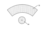
- FIG. 3 is an example of an in-mold label using the gas barrier laminate of the present invention.
- FIG. 4 is a cross-sectional view of an example of a packaging container formed by in-molding the gas barrier laminate of the present invention.
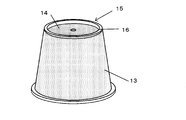
- FIG. 5 is a perspective view of an example of a packaging container formed by in-molding the gas barrier laminate of the present invention from the bottom side.
- the gas barrier laminate of the present invention is formed from a thermoplastic resin film between a resin film layer (B) having a recording layer (D) and a resin film layer (C) having a heat seal layer (E). It is comprised from the laminated body which laminated
- the thickness of the resin film layer (B) constituting the gas barrier laminate of the present invention is preferably 5 to 200 ⁇ m
- the thickness of the resin film layer (C) is preferably 5 to 200 ⁇ m
- the gas barrier layer ( The thickness of A) is preferably 1 to 50 ⁇ m.
- the gas barrier layer (A) is a layer in the thickness direction of the gas barrier laminate for the purpose of barriering the permeation of gases such as oxygen, carbon dioxide, nitrogen, other inorganic gases, and organic gases in the gas barrier laminate.
- the gas barrier layer (A) uses a thermoplastic resin film from the viewpoints of flexibility, impact resistance, and pinhole resistance.
- the gas barrier laminate obtained has an oxygen gas permeability in the range of 0.001 to 5 cm 3 / (m 2 ⁇ 24 h ⁇ atm) at 23 ° C. and 0% RH.
- Oxygen gas permeability of the gas barrier layered product of the present invention 5 cm 3 / is preferably (m 2 ⁇ 24h ⁇ atm) or less, more preferably 3cm 3 / (m 2 ⁇ 24h ⁇ atm) or less More preferably, it is 1 cm 3 / (m 2 ⁇ 24 h ⁇ atm) or less. If the oxygen gas permeability of the gas barrier laminate exceeds 5 cm 3 / (m 2 ⁇ 24 h ⁇ atm), the contents such as food, cosmetics, chemicals, industrial chemicals, agricultural chemicals, electronic parts, and machine parts are packaged long.
- the oxygen gas permeability is preferably 0.001cm 3 / (m 2 ⁇ 24h ⁇ atm) or higher, more preferably 0.005cm 3 / (m 2 ⁇ 24h ⁇ atm) or more, 0 More preferably, it is 0.01 cm 3 / (m 2 ⁇ 24 h ⁇ atm) or more. If the oxygen gas permeability is 0.001 cm 3 / (m 2 ⁇ 24 h ⁇ atm) or more, it can withstand practical use.
- thermoplastic resin having gas barrier properties examples include vinyl alcohol resin (PVA), ethylene / vinyl alcohol copolymer resin (EVA), acrylonitrile resin (AN), vinylidene chloride resin (PVDC), and nylon 6 (PA6).
- PVA vinyl alcohol resin
- EVA ethylene / vinyl alcohol copolymer resin
- AN acrylonitrile resin
- PVDC vinylidene chloride resin
- PA6 nylon 6
- a vinyl alcohol resin and an ethylene / vinyl alcohol copolymer resin having a high gas barrier property and good moldability are particularly preferable. It is preferable to use a vinyl alcohol resin containing at least one of the above, and it is particularly preferable to use a vinyl alcohol resin because of its high gas barrier property.
- the vinyl alcohol resin can be produced by saponifying a vinyl ester polymer obtained by polymerizing a vinyl ester.
- vinyl esters include vinyl acetate, vinyl formate, vinyl propionate, vinyl butyrate, vinyl pivalate, vinyl versatate, vinyl laurate, vinyl stearate, and vinyl benzoate.
- vinyl acetate is preferably used from the viewpoints of availability, ease of production of vinyl alcohol resin, cost, and the like.
- the vinyl alcohol resin is not limited to a saponified product of a homopolymer of vinyl ester, and a copolymer with other monomers copolymerizable with vinyl ester as long as the effects of the present invention are not impaired.
- a saponified product of the above, a polyvinyl acetal in which a part of the hydroxyl group of the vinyl alcohol resin is cross-linked, and the like can also be used. In the present invention, these are collectively referred to as a vinyl alcohol resin.
- ⁇ -olefins having 2 to 30 carbon atoms such as ethylene, propylene, 1-butene and isobutene;
- (Meth) acrylic acid and its salts Methyl (meth) acrylate, ethyl (meth) acrylate, n-propyl (meth) acrylate, i-propyl (meth) acrylate, n-butyl (meth) acrylate, i-butyl (meth) acrylate, (Meth) acrylic acid esters such as t-butyl (meth) acrylate, 2-ethylhexyl (meth) acrylate, dodecyl (meth) acrylate, octadecyl (meth) acrylate; (Meth) acrylamide, N-methyl (meth) acrylamide, N-ethyl (meth)
- the degree of polymerization of the vinyl alcohol resin used in the present invention is preferably 500 or more, more preferably 700 or more, and still more preferably 1000 or more from the viewpoint of the mechanical properties of the film. If the degree of polymerization of the vinyl alcohol resin is 500 or more, there is no possibility that the film becomes brittle. On the other hand, the degree of polymerization of the vinyl alcohol resin is preferably 3000 or less, more preferably 2500 or less, and further preferably 2000 or less. If the degree of polymerization of the vinyl alcohol resin is 3000 or less, the melt viscosity of the vinyl alcohol resin will not be too high, and there is no possibility that the hot melt moldability will be poor.
- the degree of polymerization of the vinyl alcohol resin referred to in this specification means an average degree of polymerization measured according to JIS-K-6726: 1994.
- the degree of saponification of the vinyl alcohol resin is preferably 85 mol% or more, more preferably 90 mol% or more, and more preferably 97 mol% or more from the viewpoint of improving the moldability of the resulting vinyl alcohol resin film. Preferably, 98 mol% or more is most preferable. If the saponification degree of the vinyl alcohol resin is 85 mol% or more, the vinyl alcohol resin film will not be too high in adhesiveness, and the vinyl alcohol resin film will be continuously manufactured industrially by a hot melt molding method. Becomes easier.
- the saponification degree of the vinyl alcohol resin is based on the total number of moles of units (typically vinyl ester units) that can be converted into vinyl alcohol units by saponification among the structural units constituting the polymer. The ratio (mol%) of the unit actually saponified to the vinyl alcohol unit.
- the saponification degree of the vinyl alcohol resin can be measured according to the method described in JIS-K-6726: 1994.
- the forming method for forming the gas barrier layer (A) is not particularly limited, and various known forming methods can be used. Specifically, a cast molding method that uses a single-layer or multi-layer T die or I die connected to a screw-type extruder to extrude the molten resin into a sheet, and a circular die to extrude the molten resin into a tube.
- Inflation molding method that expands by internal air pressure
- calendar molding method that rolls the kneaded material with a plurality of hot rolls to process it into a sheet
- a drum that is dissolved in a solvent such as water and has a smooth surface (casting)
- a solution method in which a solution is poured onto a smooth belt made of a drum) or a stainless steel, and is attached to the belt, followed by drying through a heating step.
- the gas barrier layer (A) is preferably stretched at least in a uniaxial direction, and more preferably stretched in a biaxial direction substantially perpendicular to the gas barrier layer (A).
- the gas barrier resin tends to further improve the gas barrier property due to the stretching by stretching. Since biaxial stretching tends to increase the final stretching ratio more easily than uniaxial stretching, a gas barrier layer (A) having better gas barrier properties can be obtained.
- the stretching method include inter-roll stretching utilizing the peripheral speed difference of the roll group, roll rolling by the roll pressure, stretching by a tenter clip, reblow stretching by inflation molding, and the like.
- the gas barrier layer (A) is a biaxially stretched film
- these methods may be combined, or simultaneous biaxial stretching using a tenter clip or reblow stretching by inflation molding may be used.
- the draw ratio is not particularly limited, and is appropriately determined in consideration of the characteristics of the thermoplastic resin used for the gas barrier layer (A) of the present invention.
- a vinyl alcohol resin is used, it is preferably about 1.2 to 20 times, more preferably 2 to 15 times when stretched in a uniaxial direction.
- the area magnification is preferably 2 to 30 times, and more preferably 3 to 20 times. If necessary, the stretched gas barrier layer (A) can be subjected to heat treatment at a higher temperature.
- the thickness of the gas barrier layer (A) is preferably 1 ⁇ m or more, more preferably 3 ⁇ m or more, and particularly preferably 5 ⁇ m or more.
- the thickness of the gas barrier layer (A) is preferably 50 ⁇ m or less, more preferably 40 ⁇ m or less, and particularly preferably 30 ⁇ m or less. If the thickness of the gas barrier layer (A) is 50 ⁇ m or less, the rigidity of the same layer can be reduced, so that the gas barrier laminate can be given flexibility and can be easily used as a packaging material. It becomes.
- the resin film layer (B) constituting the gas barrier laminate of the present invention is specifically a film formed from a thermoplastic resin and serves as a support for the recording layer (D).
- the gas barrier layer (A) is a vinyl alcohol resin or an ethylene / vinyl alcohol copolymer resin
- an excellent gas barrier property can be obtained.
- the layer (B) it is preferable to use a film layer having excellent moisture resistance.
- thermoplastic resin Such a thermoplastic resin is not particularly limited as long as the gas barrier laminate obtained has a moisture permeability of 0.01 to 10 g / (m 2 ⁇ 24 h) at 38 ° C. and 90% RH.
- Moisture permeability of the gas barrier laminate of the present invention is preferably not more than 10g / (m 2 ⁇ 24h) , more preferably 7g / (m 2 ⁇ 24h) or less, 5g / (m 2 ⁇ 24h More preferably: When the moisture permeability of the gas barrier laminate exceeds 10 g / (m 2 ⁇ 24 h), the gas barrier performance of the gas barrier laminate changes depending on the humidity, and the desired performance of the present invention may not be exhibited.
- the moisture permeability is preferably 0.01 cm 3 / (m 2 ⁇ 24 h ⁇ atm) or more, more preferably 0.05 cm 3 / (m 2 ⁇ 24 h ⁇ atm) or more, and 0.1 cm 3 / (M 2 ⁇ 24h ⁇ atm) or more is more preferable, and 0.5 cm 3 / (m 2 ⁇ 24h ⁇ atm) or more is particularly preferable. If the moisture permeability is 0.01 cm 3 / (m 2 ⁇ 24 h ⁇ atm) or more, it can be practically used.
- thermoplastic resins include high-density polyethylene, medium-density polyethylene, low-density polyethylene, propylene-based resins, polyolefin resins such as polymethyl-1-pentene; ethylene / vinyl acetate copolymers, ethylene / acrylic acid, and the like.
- Functional group-containing polyolefin resins such as copolymers, maleic acid-modified polyethylene and maleic acid-modified polypropylene; polyamide resins such as nylon-6 and nylon-6, 6; polyethylene terephthalate and copolymers thereof, polybutylene terephthalate, or Thermoplastic polyester resins such as polybutylene succinate and aliphatic polyester such as polylactic acid; polycarbonate, atactic polystyrene, syndiotactic polystyrene and the like can be used.
- thermoplastic resins it is preferable to use a polyolefin resin or a functional group-containing polyolefin resin excellent in moisture resistance and processability, and it is particularly preferable to use a polyolefin resin.
- polyolefin resins include homopolymers of olefins such as ethylene, propylene, butylene, hexene, octene, butadiene, isoprene, chloroprene, methyl-1-pentene, and two or more of these olefins.
- the copolymer which consists of is mentioned.
- propylene resins are preferably used in terms of moisture resistance, processability, mechanical strength, cost, and the like.
- propylene resin examples include isotactic or syndiotactic and polypropylene (propylene homopolymer) having various degrees of stereoregularity, propylene as a main component, ethylene, 1-butene, 1-hexene, It is desirable to use a propylene copolymer obtained by copolymerizing an ⁇ -olefin such as 1-heptene or 4-methyl-1-pentene as a main component.
- the propylene-based copolymer may be composed of a binary system mainly containing propylene, or may be composed of a ternary system or more, and may be a random copolymer or a block copolymer.
- the propylene resin may be used by blending 2 to 25% by weight of a resin having a melting point lower than that of the propylene homopolymer.
- a resin having a low melting point include high-density or low-density polyethylene.
- functional group-containing polyolefin resins include copolymers with functional group-containing monomers copolymerizable with the olefins.
- functional group-containing monomers include styrenes such as styrene and ⁇ -methylstyrene; vinyl acetate, vinyl propionate, vinyl butyrate, vinyl pivalate, vinyl caproate, vinyl laurate, vinyl stearate, vinyl benzoate, and butyl.
- Carboxylic acid vinyl esters such as vinyl benzoate and vinyl cyclohexanecarboxylate (or vinyl alcohol obtained by saponifying these carboxylic acid vinyl esters after copolymerization); acrylic acid, methacrylic acid, methyl (meth) acrylate, ethyl ( (Meth) acrylate, butyl (meth) acrylate, hexyl (meth) acrylate, octyl (meth) acrylate, 2-ethylhexyl (meth) acrylate, stearyl (meth) acrylate, benzyl (meth) acrylate, cyclohex (Meth) acrylic acid esters such as sil (meth) acrylate, isobornyl (meth) acrylate and dicyclopentanyl (meth) acrylate; (meth) acrylamides such as (meth) acrylamide and N-metalol (meth) acrylamide; Typical examples include vinyl ether
- these polyolefin-based resins and functional group-containing polyolefin-based resins can be used as necessary in order to improve the adhesion and processability of the thermoplastic resin film.
- a known method can be used for graft modification of the resin. Specific examples include graft-modified products with unsaturated carboxylic acids or derivatives thereof. Examples of the unsaturated carboxylic acid include acrylic acid, methacrylic acid, maleic acid, fumaric acid, itaconic acid, citraconic acid and the like. Examples of the unsaturated carboxylic acid derivative include acid anhydrides, esterified products, amidated products, imidized products, and metal salts of the unsaturated carboxylic acids.
- a thermoplastic resin used for the resin film layer (B) one type may be selected from the thermoplastic resins described above and used alone, or two or more types may be selected and used in combination. Good.
- what added at least one of the inorganic fine powder and the organic filler to the resin resin film layer (B) may be used. By adding the inorganic fine powder or the organic filler, the color and opacity of the film and the thermoplastic resin sheets can be made difficult to stick to each other. Moreover, it becomes easy to form a void
- inorganic fine powder examples include calcium carbonate, calcined clay, silica, diatomaceous earth, white clay, talc, titanium oxide, barium sulfate, barium titanate, alumina, zeolite, mica, sericite, bentonite, sepiolite, vermiculite, Dolomite, wollastonite, glass fiber, and the like can be used.
- one having an average particle diameter measured by a particle size distribution meter by laser diffraction is usually from 0.01 to 15 ⁇ m, preferably from 0.1 to 5 ⁇ m.
- the organic filler it is preferable to select a different type of resin from the thermoplastic resin that is the main component of the resin film layer (B).
- the thermoplastic resin is a polyolefin resin
- the organic filler may be a polymer such as polyethylene terephthalate, polybutylene terephthalate, polycarbonate, nylon-6, nylon-6,6, cyclic polyolefin, polystyrene, polymethacrylate, etc.
- an incompatible material having a melting point (for example, 170 to 300 ° C.) higher than that of the polyolefin resin or a glass transition temperature (for example, 170 to 280 ° C.) higher than that of the polyolefin resin can be used.
- the total amount of these inorganic fine powder or organic filler in the resin film layer (B) is preferably 0 to 60% by weight, and more preferably 0 to 50% by weight.
- a heat stabilizer antioxidant
- a light stabilizer a dispersant, a lubricant, a nucleating agent, and the like
- a heat stabilizer a sterically hindered phenolic antioxidant, a phosphorus antioxidant, an amine antioxidant, or the like
- a light stabilizer a sterically hindered amine light stabilizer, a benzotriazole light stabilizer, or a benzophenone light stabilizer can usually be used in the range of 0.001 to 1% by weight.
- the dispersant and the lubricant are used for the purpose of dispersing the inorganic fine powder, for example.
- silane coupling agents, higher fatty acids such as oleic acid and stearic acid, metal soaps, polyacrylic acid, polymethacrylic acid or salts thereof are usually used in the range of 0.01 to 4% by weight. be able to.
- the resin film layer (B) may have a single layer structure or a multilayer structure having a two-layer structure or a three-layer structure or more.
- the resin film layer (B) can be added with various functions such as improvement of mechanical properties, writing property, scratch resistance, suitability for secondary processing, etc. by multilayering.
- various known methods can be used. Specific examples include a dry laminate method, a wet laminate method and a melt laminate method using various adhesives, Examples thereof include a multilayer die method (coextrusion method) using a feed block and a multi-manifold, an extrusion lamination method using a plurality of dies, and a coating method using various coaters. It is also possible to use a combination of multilayer dies and extrusion lamination.
- the resin film layer (B) preferably includes a stretched resin film stretched in at least one axial direction. Since the resin film layer (B) obtained by stretching has high moisture resistance and mechanical strength and excellent thickness uniformity, a gas barrier laminate having excellent post-processability can be obtained.
- the number of stretching axes of each layer constituting the resin film layer (B) is 1 axis / 1 axis, 1 axis / 2 axis, 2 axis / 1 axis, 1 axis / 1 axis / 2 axis, 1 axis / 2 axis / 1 axis, 2 axis / 1 axis / 1 axis, 1 axis / 2 axis / 2 axis, 2 axis / 2 axis / 1 axis, 2 axis / 2 axis / 2 axis, Also good.
- the stretching of the resin film layer (B) can be performed by any one of a variety of commonly used methods or a combination thereof.
- Specific stretching methods include longitudinal stretching utilizing the difference in peripheral speed of the roll group, transverse stretching using a tenter oven, sequential biaxial stretching combining longitudinal stretching and transverse stretching, roll rolling by roll pressure, tenter Examples thereof include simultaneous biaxial stretching by a combination of an oven and a linear motor, and simultaneous biaxial stretching by a combination of a tenter oven and a pantograph.
- examples of the method for stretching the inflation film include simultaneous biaxial stretching by a tubular method.
- the stretching ratio is not particularly limited, and is appropriately determined in consideration of the properties of the thermoplastic resin used for the resin film layer (B) and the physical properties of the resulting resin film layer (B).
- the draw ratio is preferably 1.5 to 12 times, and preferably 2 to 10 times. It is more preferable.
- the area magnification is preferably 1.5 to 60 times, and more preferably 4 to 50 times.
- the draw ratio is preferably 1.2 to 10 times, more preferably 2 to 5 times. preferable.
- the area magnification is preferably 1.5 to 20 times, and more preferably 4 to 12 times.
- the stretching temperature is appropriately determined within a known temperature range suitable for stretching a thermoplastic resin having a temperature not lower than the glass transition temperature of the thermoplastic resin mainly used for the resin film layer (B) and not higher than the melting point of the crystal part.
- thermoplastic resin of the resin film layer (B) is a propylene homopolymer (melting point 155 to 167 ° C.), it is 100 to 166 ° C., and when it is a high density polyethylene (melting point 121 to 136 ° C.).
- the temperature is 70 to 135 ° C., which is 1 to 70 ° C. lower than the melting point.
- the stretching speed is preferably 20 to 350 m / min.
- the resin film layer (B) includes at least one of the inorganic fine powder and the organic filler described above and is stretched, fine pores may be formed inside the film. Formation of the holes makes it possible to reduce the weight of the resin film layer (B), improve flexibility, and improve opacity.
- the porosity calculated by the following formula (1) of the resin film layer (B) is preferably 0 to 50%, and more preferably 0 to 40%. If the porosity is 50% or less, the pores formed adjacent to each other tend to be difficult to be connected to each other. B) tends to be easily obtained.
- the resin film layer (B) has a thickness of preferably 5 ⁇ m or more, more preferably 10 ⁇ m or more, and particularly preferably 20 ⁇ m or more.
- the thickness of the resin film layer (B) is 5 ⁇ m or more, the moisture resistance of the resin film layer (B) is easily obtained, and there is a tendency that a gas barrier laminate having the desired performance of the present invention is easily obtained.
- the resin film layer (B) preferably has a thickness of 200 ⁇ m or less, more preferably 150 ⁇ m or less, and particularly preferably 100 ⁇ m or less. If the thickness of the resin film layer (B) is 200 ⁇ m or less, the rigidity of the same layer can be reduced, so that the gas barrier laminate can be given flexibility and can be easily used as a packaging material. It becomes possible.
- the resin film layer (B) includes a recording layer (D) on one surface thereof.
- the recording layer (D) in the present invention imparts printability to the gas barrier laminate and simultaneously imparts antistatic performance. By imparting printing suitability, the adhesion and water resistance of printing ink are improved, and the recording suitability is improved. In addition, the addition of antistatic performance makes it difficult for static electricity troubles to occur in the printing process and improves handling.
- the gas barrier laminate of the present invention can correspond to various printing methods. Due to the antistatic performance of the recording layer (D), the packaging bag and packaging container formed using the gas barrier laminate are also difficult to be charged, and the appearance is deteriorated because dust and dust are difficult to adhere. There are few and it becomes hygienic.
- the recording layer (D) preferably contains 1 to 70% by weight of pigment particles, 0 to 98% by weight of binder resin, and 1 to 99% by weight of antistatic agent, 5 to 60% by weight of pigment particles, and 3 to 92 binder resin. More preferably 2 to 70% by weight, and more preferably 10 to 50% by weight pigment particles, 5 to 87% by weight binder resin, and 3 to 50% by weight antistatic agent. .
- the recording layer (D) is provided as a coating layer containing these components by direct coating on the resin film layer (B), or the recording layer (D) is previously formed on another film, It is preferable to form by laminating on the resin film layer (B).
- the antistatic agent is added to impart antistatic performance to the recording layer (D).
- the antistatic agent include low molecular weight organic compound antistatic agents represented by stearic acid monoglyceride, alkyldiethanolamine, sorbitan monolaurate, alkylbenzene sulfonate, alkyl diphenyl ether sulfonate, etc .; ITO (indium doped Conductive inorganic fillers typified by tin oxide), ATO (antimony-doped tin oxide), graphite whiskers, etc .; so-called electron conductive polymers that exhibit conductivity by pi electrons in the molecular chain such as polythiophene, polypyroyl, polyaniline , And nonionic polymer-based antistatic agents such as polyethylene glycol and polyoxyethylenediamine; polyvinylbenzyltrimethylammonium chloride, polydimethylaminoethyl methacrylate quaternization Quaternary am
- each of these antistatic agents has characteristics.
- antistatic agents based on low molecular weight organic compounds are easily affected by the antistatic performance due to environmental humidity, resulting in a decrease in printing ink transferability and ink adhesion due to bleeding out.
- the conductive inorganic filler has a drawback that the antistatic effect cannot be sufficiently obtained because the fillers do not contact each other when added in a small amount.
- the binder component becomes relatively low, which makes it difficult to achieve both ink adhesion and antistatic effect. is there.
- Electronically conductive polymers generally have black, green, or blue-gray coloration due to the coloration derived from the conjugated system, and if this is used, an excellent antistatic effect can be obtained, but a gas-barrier laminate with a dull color
- a polymer having an antistatic function is preferable as the antistatic agent of the present invention because it has little influence on the adhesion and transferability of the ink and is hardly colored.
- the alkali metal salt-containing polymer has good antistatic performance even in a low-humidity environment, and has a small influence on the expression of antistatic performance due to environmental humidity, so it was molded using the gas barrier laminate of the present invention. Anti-staining effect on packaging bags and containers can be expected.
- the weight ratio of each structural unit (a), (b), and (c) at the time of copolymerization is preferably 20 to 70:30 to 80: 0 to 20 (wt%), particularly preferably 30 to 60. : 40-70: 0-10 (wt%).
- the polyalkylene oxide compound monomer forming the structural unit (a) is an ester of acrylic acid or methacrylic acid represented by the following general formula (Formula 2).
- the unit is a component that contributes to the antistatic function by anions and alkali metal ions in the structure. If the same component in the polymer is less than 1% by weight, a sufficient antistatic effect cannot be provided. If it exceeds 99% by weight, it becomes excessively water-soluble and causes stickiness under high humidity conditions.
- R 10 is a hydrogen atom or a methyl group
- R 11 is a hydrogen atom, a chlorine atom or a methyl group
- A is one type of linking group selected from the following ⁇ Group 1>, or One or more linking groups selected from ⁇ Group 1> and one or more linking groups selected from the following ⁇ Group 2> are alternately linked or a single bond
- M is an alkali.
- Metal ion, n represents an integer of 1 to 100.
- ⁇ Group 1> An optionally substituted alkylene group having 1 to 6 carbon atoms, Arylene group having 6 to 20 carbon atoms which may have a substituent ⁇ Group 2> —CONH—, —NHCO—, —OCONH—, —NHCOO—, —NH—, —COO—, —OCO—, —O— M represents an alkali metal, and n represents an integer of 1 to 100. When n is 2 or more, R 11 may be the same or different. )
- Examples of the ⁇ Group 1> alkylene group having 1 to 6 carbon atoms include a methylene group, an ethylene group, a propylene group, a butylene group, a pentylene group, and a hexylene group, which are linear or branched. Although it may be, it is preferably linear.
- Examples of the substituent include a hydroxyl group and an aryl group.
- Examples of the arylene group having 6 to 20 carbon atoms include a phenylene group, a naphthylene group, and an anthrylene group.
- Examples of the substituent include a hydroxyl group and an alkyl group.
- Examples of the arylene group substituted with an alkyl group include a tolylene group and a xylylene group.
- a coupling group selected from ⁇ Group 2> a urethane group or an ester group can be preferably selected.
- linking group in which one or more linking groups selected from ⁇ Group 1> and one or more linking groups selected from ⁇ Group 2> are alternately bonded, “(the linking group selected from Group 1” is used. )-(Linking group selected from group 2) "or” (linking group selected from group 1)-(linking group selected from group 2)-(selected from group 1) Linking group)-(linking group selected from Group 2) "and the like.
- the two types (the linking group selected from the first group) may be the same as or different from each other, and the two types (the linking group selected from the second group) are the same as each other. It may or may not be.
- n R 11 s may be the same or different, but are preferably the same.
- n represents an integer of 1 to 100, preferably 2 to 50, more preferably 3 to 50.
- R 11 is a hydrogen atom
- n is selected from the range of 10 to 35, preferably 15 to 30, more preferably 20 to 25, and when R 11 is a methyl group, n is 1 to 20, preferably Can be selected from the range of 3 to 16, more preferably 5 to 14.
- M is an alkali metal, and examples thereof include lithium, sodium, and potassium.
- polyalkylene oxide compound monomer examples include (poly) ethylene glycol (meth) acrylate, (poly) propylene glycol (meth) acrylate, and (poly) chloroethylene glycol (meta). ) Acrylate, (poly) tetramethylene glycol (meth) acrylate, methoxy (poly) ethylene glycol (meth) acrylate, and (poly) alkylene oxide (meth) acrylate such as methoxy (poly) propylene glycol (meth) acrylate.
- an alkylene oxide monomer having a linking group other than a single bond at a position corresponding to A in the general formula (Formula 2) is also included.
- a compound described in Japanese Patent Application Laid-Open No. 09-113704 can be used as the compound having a urethane bond in A.
- the method for introducing an alkali metal corresponding to M is not particularly limited, but it is usually possible to impart ion conductivity by alkali metal ions by reacting an alkylene oxide monomer with an alkali metal salt to ionize the hydroxyl terminal.
- alkali metal salts that can be suitably used in the present invention include lithium, sodium or potassium perchlorates, or inorganic salts such as chlorides, bromides, iodides, and thiocyanides. By adding these inorganic salts to the polyalkylene oxide compound monomer to alkoxide, ionic conductivity due to alkali metal ions can be obtained.
- Japanese Laid-Open Patent Publication No. 09-113704 proposes an alkoxide compound having a urethane bond at A in the above general formula (Formula 2).
- the alkali metal ion examples include the above-mentioned lithium, sodium, potassium, etc. Among them, lithium having a small ion radius is preferably used.
- the alkali metal ion concentration is preferably 0.01 to 1.00% by weight, more preferably 0.01 to 0.70% by weight, still more preferably 0.01 to 0.50% by weight. It is desirable to add a polymer having an antistatic function so that the concentration becomes less than 0.01% by weight. When the alkali metal ion concentration is less than 0.01% by weight, a sufficient antistatic effect cannot be obtained. Although the prevention effect is obtained, the adhesion with the printing ink is lowered due to the increase of metal ions.
- the hydrophobic monomer forming the structural unit (b) is an ester of acrylic acid or methacrylic acid represented by the following general formula (Formula 3).
- the unit imparts lipophilicity to the alkali metal salt-containing polymer, and is a component that contributes to water resistance and printing ink transferability. Copolymerization with a hydrophobic monomer is required to achieve both printability and antistatic properties. When the same component in the polymer is less than 0% by weight, the above effect is lowered. On the other hand, if it exceeds 99% by weight, the antistatic effect is relatively lowered.
- R 8 is a hydrogen atom or a methyl group
- R 9 is an alkyl group having 1 to 30 carbon atoms, an aralkyl group having 7 to 22 carbon atoms, or a cyclohexane having 5 to 22 carbon atoms.
- Specific examples of the monomer that forms the structural unit represented by the general formula (Chemical Formula 3) include methyl (meth) acrylate, ethyl (meth) acrylate, butyl (meth) acrylate, isobutyl (meth) acrylate, and tarsha Examples include alkyl (meth) acrylates such as libutyl (meth) acrylate, cyclohexyl (meth) acrylate, 2-ethylhexyl (meth) acrylate, lauryl (meth) acrylate, tridecyl (meth) acrylate, and stearyl (meth) acrylate. it can.
- (C) Other monomer units that can be copolymerized Other monomer units that can be copolymerized with the monomer (a) component and the monomer (b) component, which are used for copolymerization as necessary.
- the monomer unit include hydrophobic monomers such as styrene, vinyl toluene, and vinyl acetate represented by the following general formulas (Chemical Formula 4) to (Chemical Formula 8), and hydrophilic monomers such as vinylpyrrolidone and (meth) acrylamide.
- a polymer can be mentioned.
- These monomers can be suitably incorporated as the structural unit (c) in the alkali metal salt-containing polymer. The unit facilitates copolymerization of the polymer and adjusts the solubility in a solvent when preparing the coating solution.
- the alkali metal salt-containing polymer that can be used in the present invention includes a polyalkylene oxide compound monomer structural unit (a) represented by the above general formula (Formula 2) and a hydrophobicity represented by the above general formula (Formula 3). It can be produced by copolymerizing the monomer structural unit (b) and the monomer structural unit (c) such as the above general formulas (Chemical Formula 4) to (Chemical Formula 8) that can be copolymerized therewith. .
- the method for producing the alkali metal salt-containing polymer is not particularly limited, and can be appropriately used alone or in combination with known polymerization techniques. Usually, bulk polymerization, solution polymerization, emulsion polymerization, etc. using a radical initiator are used. It is preferable to employ a known polymerization method.
- a more preferable polymerization method is a solution polymerization method.
- a polyalkylene oxide compound monomer structural unit (a), a hydrophobic monomer structural unit (b), a copolymerizable monomer structural unit (c), and the like used as a raw material under a nitrogen stream
- the monomer of is an inert organic solvent such as n-hexane, n-butanol, 2-propanol, toluene, xylene, methyl ethyl ketone, acetone, methyl isobutyl ketone, cyclohexanone, ethyl acetate, isopropyl acetate, butyl acetate, tetrahydrofuran, ethyl cellosolve, It is carried out by dissolving in butyl cellosolve, propylene glycol monoethyl ether, etc., adding a radical polymerization initiator thereto, and then stirring while heating
- the polymerization time is usually set to 1 to 24 hours.
- the monomer solid concentration during polymerization is usually 10 to 60% by weight, and the concentration of the polymerization initiator is usually 0.1 to 10% by weight with respect to the monomer.
- the molecular weight of the alkali metal salt-containing polymer can be set at an arbitrary level depending on the polymerization conditions such as the polymerization temperature, the polymerization time, the type and amount of the polymerization initiator, the amount of solvent used, and the chain transfer agent.
- the polymerization initiator used for copolymerization is preferably fat-soluble, and examples of suitable polymerization initiators include organic peroxides and azonitriles.
- Organic peroxides include alkyl peroxides (dialkyl peroxides), aryl peroxides (diaryl peroxides), acyl peroxides (diacyl peroxides), aroyl peroxides (diaroyl peroxides), ketone peroxides, peroxides Carbonates (peroxydicarbonates), peroxycarbonates, peroxycarboxylates, hydroperoxides, peroxyketals, peroxyesters and the like are included.
- alkyl peroxide examples include diisopropyl peroxide, ditertiary butyl peroxide, and tertiary butyl hydroperoxide.
- aryl peroxide examples include dicumyl peroxide and cumyl hydroperoxide.
- acyl peroxide examples include dilauroyl peroxide.
- aroyl peroxide examples include dibenzoyl peroxide.
- ketone peroxide include methyl ethyl ketone peroxide and cyclohexanone peroxide.
- azonitrile examples include azobisisobutylnitrile and azobisisopropionitrile.
- the resulting alkali metal salt-containing polymer preferably contains a structural unit represented by the following general formula (1).
- R 1 and R 2 each independently represents a hydrogen atom or a methyl group
- R 3 represents a hydrogen atom, a chlorine atom or a methyl group
- R 4 represents an alkyl group having 1 to 30 carbon atoms
- a Is one type of linking group selected from the following ⁇ Group 1>, or one or more types of linking groups selected from the following ⁇ Group 1> and one or more types of linkage selected from the following ⁇ Group 2> Represents a linking group in which the groups are alternately bonded or a single bond
- Arylene group having 6 to 20 carbon atoms which may have a substituent ⁇ Group 2> —CONH—, —NHCO—, —OCONH—, —NHCOO—, —NH—, —COO—, —OCO—, —O—
- M represents an alkali metal
- m represents an integer of 0 to 300
- the molecular weight of the obtained alkali metal salt-containing polymer is preferably such that the weight average molecular weight measured by gel permeation chromatography (GPC) is in the range of 10,000 to 1,000,000. If the molecular weight is 10,000 or more, the polymer is difficult to ooze out from the formed recording layer (D), so that sufficient water resistance tends to be obtained. If the molecular weight is 1,000,000 or less, it tends to be miscible with the binder component, so that coating defects are less likely to occur and a uniform antistatic effect tends to be obtained.
- GPC gel permeation chromatography
- the recording layer (D) of the present invention may contain a polymer binder as necessary.
- the polymer binder provides adhesion between the recording layer (D) and the resin film layer (B) on which the recording layer (D) is provided, or another film, and improves adhesion with the printing ink.
- Specific examples of the polymeric binder include polyethyleneimine, alkyl-modified polyethyleneimine having 1 to 12 carbon atoms, poly (ethyleneimine-urea), ethyleneimine adduct of poly (ethyleneimine-urea), polyamine polyamide, and polyamine polyamide.
- Polyethyleneimine polymers such as ethyleneimine adduct and epichlorohydrin adduct of polyamine polyamide, acrylic ester copolymer, methacrylic ester copolymer, acrylic amide-acrylic ester copolymer, acrylic amide-acrylic Acid ester-methacrylic acid ester copolymers, polyacrylamide derivatives, acrylic acid ester polymers such as oxazoline group-containing acrylic acid ester polymers, polyvinylpyrrolidone, polyethylene glycol, etc.
- polymer binders may be used alone or in combination of two or more. These polymer binders can be used in the form diluted or dispersed in an organic solvent or water.
- urethane resins such as polyether urethane, polyester polyurethane, and acrylic urethane, or acrylic acid ester copolymers have good compatibility with the aforementioned ionic polymer-based polymer having an antistatic function, that is, compatibility is good. It is stable when mixed and used as a paint, and is easy to apply and preferable.
- the recording layer (D) of the present invention preferably contains pigment particles.
- the recording layer (D) can contain pigment particles in the range of 1 to 70% by weight.
- Pigment particles improve the fixability of printing inks due to their oil absorption, improve surface texture and gloss as extender pigments, improve whiteness as white pigments, improve anti-blocking performance by imparting surface irregularities, light resistance and weather resistance as UV reflectors In view of imparting performance such as improvement in performance, it can be appropriately selected and used.
- pigment particles organic and inorganic fine powders are used. Specific examples include silicon oxide, calcium carbonate, calcined clay, titanium oxide, zinc oxide, barium sulfate, diatomaceous earth, acrylic particles, styrene particles, polyethylene particles, Polypropylene particles and the like can be used.
- the particle diameter of the pigment particles is preferably 20 ⁇ m or less, more preferably 15 ⁇ m or less. When the particle diameter of the pigment particles exceeds 20 ⁇ m, the pigment particles easily fall off from the formed coating layer, and a powder blowing phenomenon occurs.
- the pigment particle content in the recording layer (D) is preferably in the range of 1 to 70% by weight, more preferably 5 to 60% by weight, and still more preferably 10 to 50% by weight. If the content of the pigment particles is less than 1% by weight, the effect of adding the pigment particles may not be sufficiently obtained. If the content exceeds 70% by weight, the binder resin is insufficient and the cohesive strength of the recording layer (D) is insufficient. The ink tends to peel off during printing.
- the recording layer (D) can be provided as a coating layer by preparing a coating solution containing the above components, coating this on the resin film layer (B), drying and solidifying it. For coating, a conventionally known method or apparatus can be used.
- the recording layer (D) can also be provided on the resin film layer (B) by lamination. In this case, another film provided with the recording layer (D) in advance may be prepared and laminated on the resin film layer (B).
- Lamination can be performed by a technique such as ordinary dry lamination, wet lamination, melt lamination, or heat lamination.
- the recording layer (D) of the present invention has antistatic performance.
- the surface resistivity of the recording layer (D) side surface is adjusted to be in the range of 1 ⁇ 10 8 to 9 ⁇ 10 12 ⁇ .
- the surface resistivity of the recording layer (D) is preferably in the range of 5 ⁇ 10 8 to 9 ⁇ 10 11 ⁇ , and more preferably in the range of 1 ⁇ 10 9 to 9 ⁇ 10 10 ⁇ .
- the surface resistivity of the recording layer (D) exceeds 9 ⁇ 10 12 ⁇ , sufficient antistatic performance cannot be imparted to the gas barrier laminate, and dust and dirt are collected on the gas barrier laminate in the printing process.
- the surface resistivity of the recording layer (D) is preferably as low as possible for the same purpose, but it is technically possible that the surface resistivity of the recording layer (D) formed by the above formulation can be lower than 1 ⁇ 10 8. Have difficulty.
- the thickness of the recording layer (D) is preferably 0.01 to 50 ⁇ m, more preferably 0.05 to 30 ⁇ m, still more preferably 0.1 to 10 ⁇ m, and 0.3 to 8 ⁇ m. It is particularly preferred that When the film thickness is less than 0.01 ⁇ m, it is difficult to maintain the uniformity of the recording layer (D), and the antistatic performance and the water resistance of the printing ink may not be obtained. On the other hand, if it exceeds 50 ⁇ m, the recording layer (D) tends to become brittle, and ink peeling may occur due to cohesive failure of the recording layer (D).
- the resin film layer (C) constituting the gas barrier laminate of the present invention is specifically a film formed from a thermoplastic resin and serves as a support for the heat seal layer (E).
- the resin film layer (C) constituting the gas barrier laminate of the present invention is preferably a film layer formed from a thermoplastic resin having excellent moisture resistance.
- the resin film layer (C) can be obtained by using the thermoplastic resin described in the resin film layer (B), an inorganic fine powder and an organic filler, and molding it by the same molding technique as the resin film layer (B). it can.
- the resin film layer (C) can have the same thickness as the resin film layer (B). Among them, it is preferable to include a biaxially stretched film of an olefin resin.
- the resulting gas barrier laminate is less likely to curl even when the temperature and humidity environment changes. Handleability in the process is improved.
- a biaxially stretched polypropylene film for the resin film layer (B) it is preferable to use a biaxially stretched polypropylene film for the resin film layer (C).
- the difference in thickness between the resin film layer (B) and the resin film layer (C) is preferably 30% or less, more preferably 20% or less, as a ratio based on the thick film layer. More preferably, it is 10% or less. If the ratio is 30% or less, it is easy to obtain a gas barrier laminate with less curling.
- the resin film layer (C) includes a heat seal layer (E) on one surface thereof.
- the heat seal layer (E) in the present invention imparts heat sealability to the gas barrier laminate and facilitates the formation of a packaging bag or packaging container as a packaging material.
- the gas barrier laminate of the present invention is formed in the shape of a sealed bag or a sealed container in order to minimize the contact between the contents to be stored by effectively utilizing the gas barrier property and external air. It is desirable to process and use.
- a representative example of such a processing method is heat sealing.
- the gas barrier laminate of the present invention by providing a heat seal layer (E) on the resin film layer (C), it is possible to easily form a packaging bag or a packaging container by heat sealing, and to shorten the processing time. Become.
- thermoplastic resin is used for the heat seal layer (E).
- specific examples of the thermoplastic resin used in the heat seal layer (E) include homopolymers of olefins represented by ethylene, propylene, butene, pentene, hexene, methylpentene, and octene, or of these olefins.
- Copolymers of two or more or one or more of these olefins and styrenes such as styrene and ⁇ -methylstyrene; vinyl acetate, vinyl propionate, vinyl butyrate, vinyl pivalate, vinyl caproate, vinyl laurate , Vinyl carboxylic acids such as vinyl stearate, vinyl benzoate and vinyl butyl benzoate; copolymerizable with olefins such as acrylic acid, methacrylic acid, acrylic ester, methacrylic ester, acrylic acid such as acrylonitrile
- One or more types of copolymers, Beauty include their metal salts.
- the melting point of the thermoplastic resin is preferably in the range of 60 to 150 ° C, more preferably in the range of 70 to 145 ° C, and still more preferably in the range of 80 ° C to 140 ° C. If the melting point of the thermoplastic resin is 60 ° C. or higher, the heat seal layer softens under high temperature conditions in the summer, and the heat seal strength of the product that has been blocked by the gas barrier laminate or heat sealed is high. It is easy to suppress the decline. Moreover, if melting
- Lamination of the heat seal layer (E) onto the resin film layer (C) can be performed by various known methods. For example, using a multilayer die, a feed block, a multi-manifold, etc., a method of extruding a multilayer thermoplastic resin sheet in which a resin film layer (C) and a heat seal layer (E) are laminated in advance (coextrusion), A method of extruding and laminating the heat seal layer (E) on the pre-formed resin film layer (C) (extrusion lamination), a pre-formed resin film layer (C) and a pre-formed heat seal layer (E ) Is applied via an adhesive or the like (dry lamination), or a thermoplastic resin solution, emulsion, or dispersion of the heat seal layer (E) is applied on a pre-formed resin film layer (C). Examples thereof include a method (coating method) for drying to form the heat seal layer (E).
- the heat seal layer (E) preferably has a thickness of 0.1 ⁇ m or more, more preferably 0.3 ⁇ m or more, and particularly preferably 0.5 ⁇ m or more. If the thickness of the heat seal layer (E) is 0.1 ⁇ m or more, a strong adhesive force can be obtained, and a packaging bag or a packaging container can be easily formed as a packaging material. On the other hand, the thickness of the heat seal layer (E) is preferably 20 ⁇ m or less, more preferably 15 ⁇ m or less, and particularly preferably 10 ⁇ m or less. If the thickness of the heat seal layer (E) is 20 ⁇ m or less, gas barrier properties are easily obtained, and a gas barrier laminate having the expected performance of the present invention tends to be obtained.
- the gas barrier laminate of the present invention is obtained by laminating the gas barrier layer (A), the resin film layer (B), and the resin film layer (C) constituting the gas barrier laminate. More specifically, as shown in FIG. 1, the gas barrier laminate 1 of the present invention comprises at least the recording layer (D) 5 / resin film layer (B) 3 / gas barrier layer (A) 2 / resin film layer (C 4) It is obtained by making it the laminated structure which contains the heat seal layer (E) 6 in order. Among these, the lamination of the gas barrier layer (A) and the resin film layer (B) and the lamination of the gas barrier layer (A) and the resin film layer (C) are bonded through the adhesive layers 7 and 8. However, it is simple and preferable in terms of processing steps.
- Adhesive layer The above-mentioned bonding through the adhesive layer is performed by applying and spreading a solvent-based adhesive on the surface to be bonded to any one of the gas barrier layer (A), the resin film layer (B), and the resin film layer (C). Dry lamination that is provided by a method such as dry laminating and bonding via this, hot melt type adhesive that is provided by a technique such as melt extrusion laminating, and melt extrusion that is bonded via this as an adhesive layer It can be carried out by a technique such as laminating, hot-melt adhesive hot-melt adhesive film which is melted by heat, and this is used as an adhesive layer and bonded via this.
- the adhesive When using a solvent-based adhesive, apply the adhesive on the surface of one or both of the gas barrier layer (A) and the resin film layer (B), then overlap each other and apply with a pressure roll. If the adhesive is applied onto the surface of one or both of the gas barrier layer (A) and the resin film layer (C), and then stacked on each other, and pressure bonded with a pressure roll Good.
- the solvent-based adhesive for example, resin components made of acrylic resin, urethane resin, ether resin, ester resin, epoxy resin, rubber resin, silicone resin, ABS resin, etc.
- a liquid type adhesive in the form of a solution type or an emulsion type which can be applied by dissolving, dispersing, emulsifying and diluting in the phase using a known solvent and having fluidity and coating.
- the coating of these solvent adhesives is die coater, bar coater, comma coater, lip coater, roll coater, rod coater, curtain coater, gravure coater, spray coater, blade coater, reverse coater, air knife coater, slide hopper, etc. Is done. Thereafter, smoothing is performed as necessary, and an adhesive layer can be formed through a drying step.
- the adhesive When using a hot melt type adhesive, the adhesive is applied to the surface of either the gas barrier layer (A) or the resin film layer (B) by methods such as beet coating, curtain coating, and slot coating.
- the adhesive layer is formed by applying a laminated film by extruding into a melted film from the die, and then laminating them, and then pressure-bonding them with a pressure roll.
- the adhesive On the surface of either the layer (A) or the resin film layer (C), the adhesive is applied by a method such as beet coating, curtain coating or slot coating, or the adhesive is heated and melted.
- the hot melt adhesive examples include low density polyethylene, ethylene / vinyl acetate copolymer, metal salt of ethylene / (meth) acrylic acid copolymer (so-called Surlyn), chlorinated polyethylene, chlorinated polypropylene, and the like.
- Polyolefin resins, polyamide resins, polybutyral resins, urethane resins, and the like can be used.
- the thickness of the adhesive layer is preferably 0.5 ⁇ m or more, and more preferably 1 ⁇ m or more.
- the thickness of the adhesive layer is preferably 30 ⁇ m or less, and more preferably 25 ⁇ m or less. If the thickness of the adhesive layer exceeds 30 ⁇ m, the cohesive force of the adhesive layer may be impaired, and each layer may be easily peeled off.
- the basis weight of these adhesive layers is preferably 0.5 to 30 g / m 2 and more preferably 1 to 25 g / m 2 as a solid content. It is preferable to provide an adhesive layer by coating or melt-extruding an adhesive so that the thickness and basis weight are as described above.
- At least one of an ultraviolet absorber and an ultraviolet reflector can be further added to the adhesive layer.
- the resulting gas barrier laminate has a gas barrier performance and an ultraviolet blocking performance. It is possible to obtain a gas barrier laminate, a gas barrier packaging bag, and a gas barrier packaging container that can further suppress deterioration of objects.
- the ultraviolet absorber is one that absorbs light of any wavelength in the range of 280 to 400 nm.
- the ultraviolet absorber for example, any of benzotriazole ultraviolet absorber, benzophenone ultraviolet absorber, salicylate ultraviolet absorber, cyanoacrylate ultraviolet absorber, nickel ultraviolet absorber and triazine ultraviolet absorber, or these Can be mentioned. These can be used in a low molecular weight type or a high molecular weight type.
- benzotriazole ultraviolet absorber examples include 2- (2′-hydroxy-5′-methylphenyl) benzotriazole, 2- (2′-hydroxy-3 ′, 5′-di-t- Butylphenyl) benzotriazole, 2- (2′-hydroxy-3 ′, 5′-di-t-amylphenyl) benzotriazole, 2- (2′-hydroxy-3′-t-butyl-5′- Methylphenyl) -5-chlorobenzotriazole, 2- (2′-hydroxy-3 ′-(1-methyl-1-phenylethyl) -5 ′-(1,1,3,3-tetramethylbutyl) Phenyl)) benzotriazole, 2- (2′-hydroxy-3′-t-butyl-5 ′-(2-octyloxycarbonyl) ethylphenyl) benzotriazole, and the like.
- benzophenone ultraviolet absorbers include 2,4-dihydroxybenzophenone, 2-hydroxy-4-methoxybenzophenone, 2-hydroxy-4-n-octoxybenzophenone, 2-hydroxy-4-n-dodecyl.
- examples thereof include oxybenzophenone, 2,2′-dihydroxy-4-methoxybenzophenone, 2,2′-dihydroxy-4,4′-dimethoxybenzophenone, 2,2 ′, 4,4′-tetrahydroxybenzophenone.
- salicylate ultraviolet absorbers include phenyl salicylate, 4-t-butylphenyl salicylate, 2,4-di-t-butylphenyl-3 ′, 5′-di-t-butyl-4′- Examples thereof include hydroxybenzoate.
- Specific examples of the cyanoacrylate ultraviolet absorber include ethyl ( ⁇ , ⁇ -diphenyl) cyanoacrylate and 2-ethylhexyl ( ⁇ , ⁇ -diphenyl) cyanoacrylate.
- nickel-based ultraviolet absorbers include [2,2-thiobis (4-t-octylphenolate)]-n-octylamine nickel salt, [2,2-thiobis (4-t-octylphenol) Lat)]-2-ethylhexylamine nickel salt, nickel dibutyldithiocarbamate and the like.
- Specific examples of the triazine ultraviolet absorber include 2- (4,6-diphenyl-1,3,5-triazin-2-yl) -5-[(hexyl) oxy] -phenol.
- benzotriazole-based ultraviolet absorbers are preferred because of their high ultraviolet absorption ability, and 2- (2′-hydroxy-3 ′-(1-methyl-1-phenylethyl) -5′-1,1,3, 3-tetramethylbutylphenyl) benzotriazole (CAS No. 73936-91-1), 2- (2′-hydroxy-3′-t-butyl-5 ′-(2-octyloxycarbonyl) ethylphenyl) benzotriazole (CAS No. 127519-17-9) is more preferable.
- the ultraviolet reflector is one that reflects and / or scatters light having any wavelength in the range of 280 to 400 nm.
- the ultraviolet reflector include zinc oxide, titanium oxide, cerium oxide, tungsten oxide, strontium titanate, or a mixture thereof.
- the ultraviolet absorber and the ultraviolet reflector may be used alone or in combination.
- the content of the ultraviolet absorber and the ultraviolet reflector in the adhesive layer is preferably 50% by weight or less, more preferably 40% by weight or less, and further preferably in the range of 30% by weight or less. If the amount of the ultraviolet absorber and the ultraviolet reflector is 50% by weight or less, the adhesive layer tends to have sufficient water resistance and solvent resistance.
- the thickness of the gas barrier laminate in the present invention and each layer constituting the gas barrier laminate was measured using a constant pressure thickness measuring instrument (manufactured by Teclock Co., Ltd., device name: PG-01J) in accordance with JIS-K-7130. .
- PG-01J constant pressure thickness measuring instrument
- the thickness of each layer is determined by cooling the sample to be measured with liquid nitrogen to a temperature of ⁇ 60 ° C. or lower and placing it on the glass plate.
- a sample for cross-section measurement was prepared by applying a razor blade (trade name: Proline Blade, manufactured by Chic Japan Co., Ltd.) at a right angle to the placed sample and cutting the sample, and the resulting sample was scanned using an electron microscope (Japan)
- Cross-section observation is performed using an electronic product, product name: JSM-6490), and the boundary line for each thermoplastic resin composition is determined from the composition appearance, and the entire resin film layer (B) or (C) The thickness was obtained by multiplying the observed layer thickness ratio.
- the entire gas barrier laminate is observed with a scanning electron microscope in the same manner as described above, and the boundary line for each composition is determined from the composition appearance. This was determined by multiplying the thickness of the entire gas barrier laminate by the observed layer thickness ratio.
- the basis weight of each of the gas barrier laminate and the gas barrier layer (A), the resin film layer (B), and the resin film layer (C) constituting the gas barrier laminate in the present invention is 100 mm ⁇ 100 mm in accordance with JIS-P-8124. A sample punched out in size was weighed with an electronic balance and measured.
- the surface resistivity in the present invention was measured using a double ring method electrode in accordance with JIS-K-6911 under the conditions of a temperature of 23 ° C. and a relative humidity of 50%.
- the oxygen gas permeability of the gas barrier laminate of the present invention is based on the JIS-K-7126-2 method, using a gas permeability tester (manufactured by MOCON, device name: OX-TRAN 2/21), The measurement was performed under the conditions of a temperature of 23 ° C. and a relative humidity of 0%.
- the moisture permeability of the gas barrier laminate of the present invention is based on the JIS-K-7129-B method, using a water vapor permeability tester (manufactured by MOCON, device name: PERMATRAN W3 / 33), at a temperature of 38 ° C., Measurements were made at a relative humidity of 90%.
- the gas barrier laminate of the present invention can be recorded by printing on at least one of the recording layer (D) side surface and the heat seal layer (E) side surface.
- various conventionally known methods such as offset printing, gravure printing, flexographic printing, letter press printing, screen printing, ink jet recording method, thermal recording method, thermal transfer recording method, electrophotographic recording method, etc. It is possible to use this method.
- offset printing, gravure printing, and flexographic printing methods are preferred because printed materials with excellent weather resistance and water resistance can be easily obtained.
- oil-based inks, water-based inks, and UV inks can be used as printing inks. Among these, it is preferable to use UV ink having a high drying speed.
- the gas barrier laminate of the present invention exhibits its gas barrier properties by being processed into a bag shape or a container shape and used as a packaging material for hermetically filling contents such as foods and cosmetics.
- the gas barrier laminate (recorded material) printed as shown in FIG. 2 is processed into a bag shape with only one mouth opened by heat sealing, and the opening is formed after filling the contents.
- the gas barrier packaging bag 10 can be obtained by further heat-sealing.
- in-mold labels 13 and 14 are produced from a gas barrier laminate (recorded material) as shown in FIG. 3, and are formed by vacuum / pressure forming (differential pressure forming) or injection molding.
- the in-mold molding is integrated with the injection molding member 16 so as to cover the injection molding member 16, and after filling the contents, the opening of the container is further filled with the gas barrier laminate of the present invention.
- the gas barrier packaging container 15 capable of sealing the contents can be obtained by heat sealing and closing.
- the recording layer (D) side surface of the gas barrier laminate is in contact with the inner surface of the lower female die of the differential pressure molding die as the in-mold label for differential pressure molding. Then, the resin sheet for the molding material is guided to the upper part of the lower female mold, and the resin sheet is attached to the mold shape by the differential pressure. At the same time, a gas barrier packaging container can be obtained by fusing the gas barrier laminate to the outer wall of the molded product.
- the differential pressure forming either vacuum forming or pressure forming can be adopted, but in general, differential pressure forming using both of them and utilizing plug assist is preferable.
- the gas barrier laminate of the present invention can also be suitably used as an in-mold label for injection molding in which a molten resin is injected into a mold by an injection device and cooled and solidified. Furthermore, the gas barrier laminate of the present invention can be used as an in-mold label for direct blow molding in which a parison made of a molten resin is inflated with compressed air and pressure-bonded to the inner wall of the mold, or for stretch blow molding using a preform. It can be used suitably. Since the gas barrier packaging container made of a resin molded product in which the gas barrier laminate of the present invention is bonded and integrated, the label and the resin molded product are integrally formed after the label is fixed in the mold. In addition, the resin molded product and the label have strong adhesive strength, no blister, and a gas barrier packaging container having a good appearance decorated with the label is obtained.
- Preparation Example of Recording Layer (D) Raw Material [Preparation Example 1 of Polymer Antistatic Agent] 100 parts by weight of polyethylene glycol monomethacrylate (manufactured by NOF Corporation, trade name: BLEMMER PE-350), 20 parts by weight of lithium perchlorate (manufactured by Wako Pure Chemical Industries, Ltd., reagent), hydroquinone (Wako Pure Chemical Industries, Ltd.) 4 parts equipped with a stirrer, a reflux condenser (condenser), a thermometer, and a dropping funnel, 1 part by weight, manufactured by Co., Ltd.
- [Preparation Example 2 for Polymer Antistatic Agent] 60 parts by weight of polyethylene glycol having a weight average molecular weight of 1000 (manufactured by Wako Pure Chemical Industries, Ltd., reagent), 40 parts by weight of polypropylene glycol having a weight average molecular weight of 600 (manufactured by Wako Pure Chemical Industries, Ltd., reagent), lithium perchlorate 15 parts by weight (manufactured by Wako Pure Chemical Industries, Ltd., reagent) and 400 parts by weight of methyl ethyl ketone (manufactured by Wako Pure Chemical Industries, Ltd., reagent) are mixed with a stirrer, reflux condenser (condenser), thermometer, and dropping funnel.
- a stirrer reflux condenser
- condenser condenser
- thermometer thermometer
- stearyl methacrylate manufactured by Wako Pure Chemical Industries, Ltd., reagent 10 parts by weight
- n-butyl methacrylate manufactured by Wako Pure Chemical Industries, Ltd., reagent
- azobisisobutyronitrile (Wako Pure) 2 parts by weight of Yakugyo Co., Ltd., reagent) was added and polymerized at 80 ° C. for 3 hours, and then methyl ethyl ketone (Wako Pure Chemical Industries, Ltd., reagent) was added to make the solid content 20% by weight.
- a polymer antistatic agent solution containing an alkali metal salt having a weight average molecular weight of about 100,000 and a lithium concentration of 0.6% by weight in the solid content was obtained.
- the obtained solution was a 50% toluene solution of a hydroxyl group-containing methacrylate polymer having a hydroxyl value of 65.
- 30 parts by weight of a 20% methyl ethyl ketone solution of vinyl chloride-vinyl acetate copolymer (manufactured by Shin Daiichi Vinyl Co., Ltd., trade name: ZEST C150ML) was added, and methyl ethyl ketone (Wako Pure Chemical Industries, Ltd. ( Co., Ltd., Reagent) was added to adjust the solid content to 20% by weight to obtain a polymer binder solution.
- methyl ethyl ketone manufactured by Wako Pure Chemical Industries, Ltd., reagent
- a mixed solution of 8 parts by weight of 3-aminomethyl-3,5,5-trimethylcyclohexylamine manufactured by Wako Pure Chemical Industries, Ltd., reagent
- 100 parts by weight of methyl ethyl ketone and 50 parts by weight of 2-propanol was added, and 40 ° C.
- methyl ethyl ketone was added to adjust the solid content to 20% by weight to obtain a polymer binder solution.
- the solution of the curing agent described in 1 (diluted with ethyl acetate to a solid content of 20% by weight) was added in this order so that the blending ratio described in Table 2 was obtained, and the mixture was stirred and mixed for 20 minutes. Thereafter, the coarse particle size is removed through a 100-mesh filter, diluted with methyl ethyl ketone so as to have a solid content concentration shown in Table 2, and the coating liquid (D) -1 ⁇ (D) -6 was obtained.
- Table 3 summarizes the raw materials used in the production examples of the resin film layer (B) and the resin film layer (C). From these, the thermoplastic resin compositions (a) to (f) in which the raw materials described in Table 3 were mixed in the proportions described in Table 3 were melt-kneaded in a twin-screw kneader set at 210 ° C., and then Extruded into a strand with an extruder set at 230 ° C., cooled and cut with a strand cutter to produce pellets of the thermoplastic resin compositions (a) to (f), which were used in the following production examples.
- thermoplastic resin composition (a) After melt-kneading the thermoplastic resin composition (a) with an extruder set at 230 ° C., it is supplied to an extrusion die set at 250 ° C., extruded into a sheet, and cooled to 60 ° C. by a cooling device. An unstretched sheet was obtained. This non-stretched sheet was heated to 150 ° C. and stretched 4 times in the machine direction (MD) using the peripheral speed difference of the roll group. Next, this 4-fold stretched sheet was cooled to 60 ° C., heated again to about 155 ° C. using a tenter oven, stretched 8 times in the transverse direction (TD), and then further heated by a heat setting zone adjusted to 160 ° C.
- MD machine direction
- TD transverse direction
- thermoplastic resin composition (c) and the thermoplastic resin composition (a) are melt-kneaded by three extruders set at 230 ° C., and then supplied to a coextrusion die set at 250 ° C. Then, they were laminated in a die and extruded into a sheet shape, which was cooled to 60 ° C. by a cooling device to obtain an unstretched sheet. This non-stretched sheet was heated to 140 ° C. and stretched 5 times in the machine direction by utilizing the peripheral speed difference of the roll group. Next, this 5-fold stretched sheet is cooled to 60 ° C., heated again to about 150 ° C.
- a stretched resin film having a three-layer structure [each layer resin composition (a / c / a), each layer thickness (2 ⁇ m / 36 ⁇ m / 2 ⁇ m), each layer stretching axis number (2 axes / 2 axes / 2 axes)] was obtained.
- thermoplastic resin composition (c) After melt-kneading the thermoplastic resin composition (c) in an extruder set at 230 ° C., it is supplied to an extrusion die set at 250 ° C., extruded into a sheet, and cooled to 60 ° C. by a cooling device. An unstretched sheet was obtained. This non-stretched sheet was heated to 140 ° C. and stretched 5 times in the machine direction by utilizing the peripheral speed difference of the roll group. Next, the thermoplastic resin composition (d) was melted and kneaded by two extruders set at 250 ° C., then extruded into a sheet, and laminated on both sides of the 5 ⁇ stretched sheet prepared above. A laminated sheet having a structure was obtained.
- this laminated sheet was cooled to 60 ° C., heated again to about 150 ° C. using a tenter oven and stretched 9 times in the transverse direction, and then heat-treated in a heat setting zone adjusted to 160 ° C. After cooling to 60 ° C.
- a stretched resin film having a layer structure [each layer resin composition (d / c / d), each layer thickness (10 ⁇ m / 40 ⁇ m / 10 ⁇ m), each layer stretching axis number (1 axis / 2 axes / 1 axis)] is obtained and manufactured.
- the resin film layer of Example 3 was obtained.
- thermoplastic resin composition (e) and the thermoplastic resin composition (a) are melt-kneaded by two extruders set at 230 ° C. and then supplied to a coextrusion die set at 250 ° C. Then, they were laminated in a die and extruded into a sheet shape, which was cooled to 60 ° C. by a cooling device to obtain an unstretched sheet. This non-stretched sheet was heated to 150 ° C. and stretched 4 times in the longitudinal direction by utilizing the peripheral speed difference of the roll group. Next, this 4 times stretched sheet is cooled to 60 ° C., heated again to about 155 ° C.
- thermoplastic resin composition (f), the thermoplastic resin composition (c), and the thermoplastic resin composition (a) was melt-kneaded by three extruders set at 230 ° C., and then 250 ° C. was supplied to a coextrusion die set to 1, and laminated in the die and extruded into a sheet, which was cooled to 60 ° C. by a cooling device to obtain an unstretched sheet.
- This non-stretched sheet was heated to 140 ° C. and stretched 5 times in the machine direction by utilizing the peripheral speed difference of the roll group. Next, this 5-fold stretched sheet is cooled to 60 ° C., heated again to about 150 ° C.
- the amount is 24 g / m 2 , the porosity is 42%, a three-layer structure [each layer resin composition (f / c / a), each layer thickness (2 ⁇ m / 36 ⁇ m / 2 ⁇ m), each layer stretching axis number (two axes / 2 axes / Biaxial)] was obtained, and this was used as the resin film layer of Production Example 5.
- thermoplastic resin composition (c) After melt-kneading the thermoplastic resin composition (c) in an extruder set at 230 ° C., it is supplied to an extrusion die set at 250 ° C., extruded into a sheet, and cooled to 60 ° C. by a cooling device. An unstretched sheet was obtained. This non-stretched sheet was heated to 140 ° C. and stretched 5 times in the machine direction by utilizing the peripheral speed difference of the roll group. Next, each of the thermoplastic resin composition (d) and the thermoplastic resin composition (f) is melt-kneaded in two extruders set at 250 ° C., and then supplied to an extrusion die set at 250 ° C.
- thermoplastic resin composition (d) was melt-kneaded in an extruder set at 250 ° C., then extruded into a sheet, and laminated on the other surface of the 5-fold stretched sheet prepared above, and a four-layer structure A laminated sheet was obtained.
- this laminated sheet was cooled to 60 ° C., heated again to about 150 ° C. using a tenter oven and stretched 9 times in the transverse direction, and then heat-treated in a heat setting zone adjusted to 160 ° C. Then, after cooling to 60 ° C.
- the surface of the stretched film (surface on the thermoplastic resin composition (d) side) was subjected to surface oxidation treatment by corona discharge, the thickness was 60 ⁇ m, and the basis weight was 46 g / m 2 , porosity of 32%, 4-layer structure [each resin composition (f / d / c / d), each layer thickness (4 ⁇ m / 11 ⁇ m / 30 ⁇ m / 15 ⁇ m), each layer stretching axis number (1 axis / 1 (Axis / 2 Axis / 1 Axis)] was obtained, and this was used as the resin film layer of Production Example 6.
- Example 1 On the surface of the resin film layer (B) ((B) -1) having the recording layer (D) shown in Table 5 on the resin film layer (B) side, an adhesive (trade name, manufactured by Toyo Morton Co., Ltd.) : TM-329 and trade name: CAT-18B mixed solution) were coated so that the solid content after drying was 3 g / m 2 , dried at 40 ° C. for 1 minute, and then listed in Table 5.
- the gas barrier layer (A) ((A) -1) was laminated, and both were pressure-bonded with a nip roll.
- Example 2 Comparative Examples 1 and 2
- the resin film layer (B) ((B) -1 to (B) -6) having the recording layer (D) described in Table 5 and the gas barrier layer (A) ((A ) -1 or (A) -2), and the resin film layer (C) ((C) -1 to (C) -4) having the heat seal layer (E) described in Table 5 was used.
- gas barrier laminates of Examples 2 to 4, Comparative Example 1, and Comparative Example 2 were obtained.
- Table 5 shows the surface resistivity, oxygen gas permeability, and moisture permeability measured from the obtained gas barrier laminate.
- Example 3 In Example 1, without using the gas barrier layer (A), the adhesive used in Example 1 on the surface of the resin film layer (B) -1 on the resin film layer (B) side is the same as in Example 1. Comparative Example 3 was carried out in the same manner as in Example 1 except that the adhesive film was laminated so that the adhesive film was in contact with the surface of the resin film layer (C) -1 on the resin film layer (C) side. A gas barrier laminate was obtained. Table 5 shows the surface resistivity, oxygen gas permeability, and moisture permeability measured from the obtained gas barrier laminate.
- a container having an inner diameter of 55 mm and an inner volume of about 300 ml having the cross-sectional shape shown in FIG. 4 is placed on an injection molding machine (manufactured by Nissei Plastic Industry Co., Ltd., trade name: ES3000 ELJECT) consisting of a resin extruder and a mold clamping device. A mold capable of forming individual pieces was attached. Inserted into the female mold of the same mold so that the surface on which the two types of labels are printed is in contact with the surface of the mold, and charging device (trade name: electrostatic fine sampler (JPK-3, manufactured by Kasuga Electric Co., Ltd.). )) To fix the label on the mold.
- an injection molding machine manufactured by Nissei Plastic Industry Co., Ltd., trade name: ES3000 ELJECT
- JPK-3 electrostatic fine sampler
- a propylene homopolymer (trade name: Novatec PP MA3, manufactured by Nippon Polypro Co., Ltd.) is used as the resin material for the container, and this is melted in an extruder. After kneading, it was injected into the mold at an injection pressure of about 2 t. After cooling, the container was taken out from the mold to obtain a gas barrier packaging container in which the gas barrier laminate was adhered as an in-mold label.
- the roasted coffee beans were pulverized in a powder form with a coffee mill as the contents, filled with the above containers, and punched out in the same manner as the label in a gas barrier laminate.
- the contents were sealed with a cup sealer (trade name: 300SC, manufactured by Shiga Packing Machine Co., Ltd.) to prepare an evaluation packaging container.
- the obtained recorded material was cut into a size of 150 mm ⁇ 300 mm with a guillotine cutting machine, and a heat sealer was used so that the resin film layers (C) of the two recorded materials were in contact with each other as shown in FIG. Then, the three sides were heat-sealed to form the heat-seal bonding part 12, and the gas barrier packaging bag 10 in which the recording layer (D) 5 on which the printing 11 was applied was located outside was obtained.
- roasted coffee beans were pulverized with a coffee mill into powder, filled with the above bag, heat sealed using a heat sealer to seal the contents, An evaluation packaging bag was prepared.
- the obtained evaluation packaging container and evaluation packaging bag were evaluated for the characteristics shown in the following test examples.
- the obtained evaluation results are shown in Table 5.
- the gas barrier laminate of the present invention has excellent gas barrier properties, water vapor barrier properties, heat seal properties, flexibility, impact resistance, and pinhole resistance, as well as printing and punching processes.
- the surface of the printed surface is water resistant when it is processed into a bag as a packaging container for food and cosmetics and used as a packaging container, or as an in-mold label on the outermost layer of the container. It has a feature that it is high and dust and dust are difficult to adhere.
- the gas barrier laminate of the present invention has less dust and dust adhesion due to electrification, has excellent printability, and can be used as a packaging bag after being processed into a bag shape as a packaging material for hermetically filling the contents.
- an in-mold label is attached to the outermost layer of a resin container and used as a packaging container, the chemical change of the contents can be reduced or prevented by blocking water vapor, oxygen or harmful gas.
- Gas barrier laminate 2 Gas barrier layer (A) 3 Resin film layer (B) 4 Resin film layer (C) 5 Recording layer (D) 6 Heat seal layer (E) 7, 8 Adhesive layer 10 Gas barrier packaging bag 11 Printing 12 Heat seal bonding part 13 In-mold label (for side) 14 In-mold label (for bottom surface) 15 Gas barrier packaging container 16 Injection molding member
Landscapes
- Laminated Bodies (AREA)
- Wrappers (AREA)
Abstract
L'invention concerne un stratifié faisant barrière aux gaz qui, lorsqu'il est utilisé comme matériau de conditionnement à remplir d'un contenu dans un état hermétiquement scellé ou qu'il est appliqué sur la couche externe d'un contenant en résine en tant qu'étiquette surmoulée, peut bloquer l'humidité, l'oxygène ou un gaz dangereux afin d'empêcher ou de réduire la modification chimique du contenu. Ce stratifié faisant barrière aux gaz comprend une couche de film de résine (B) munie d'une couche de support d'information (D), une couche de film de résine (C) munie d'une couche thermoscellable (E), ainsi qu'au moins une couche (A) faisant barrière aux gaz qui est constituée d'un film de résine thermoplastique et qui est intercalée entre les couches de film de résine (B) et (C), la résistivité superficielle de la couche de support d'information (D) étant comprise entre 1×10⁸ et 9×10¹² Ω.
Priority Applications (1)
| Application Number | Priority Date | Filing Date | Title |
|---|---|---|---|
| JP2014554568A JP6235489B2 (ja) | 2012-12-27 | 2013-12-26 | ガスバリア性積層体 |
Applications Claiming Priority (2)
| Application Number | Priority Date | Filing Date | Title |
|---|---|---|---|
| JP2012283841 | 2012-12-27 | ||
| JP2012-283841 | 2012-12-27 |
Publications (1)
| Publication Number | Publication Date |
|---|---|
| WO2014104237A1 true WO2014104237A1 (fr) | 2014-07-03 |
Family
ID=51021311
Family Applications (1)
| Application Number | Title | Priority Date | Filing Date |
|---|---|---|---|
| PCT/JP2013/084979 Ceased WO2014104237A1 (fr) | 2012-12-27 | 2013-12-26 | Stratifié faisant barrière aux gaz |
Country Status (2)
| Country | Link |
|---|---|
| JP (1) | JP6235489B2 (fr) |
| WO (1) | WO2014104237A1 (fr) |
Cited By (2)
| Publication number | Priority date | Publication date | Assignee | Title |
|---|---|---|---|---|
| WO2015154182A1 (fr) * | 2014-04-09 | 2015-10-15 | Ifood Systems Corporation | Étiquette pour conditionnement sous atmosphère modifiée |
| CN119529694A (zh) * | 2025-01-21 | 2025-02-28 | 浙江祥邦科技股份有限公司 | 一种一体化高阻隔封装材料及其制备方法 |
Citations (6)
| Publication number | Priority date | Publication date | Assignee | Title |
|---|---|---|---|---|
| JPH08132477A (ja) * | 1994-09-14 | 1996-05-28 | Dainippon Printing Co Ltd | インモールドラベル容器およびその製法 |
| JP2002067246A (ja) * | 2000-08-24 | 2002-03-05 | Toppan Printing Co Ltd | 帯電防止積層体およびそれを用いた包装袋 |
| JP2005305801A (ja) * | 2004-04-21 | 2005-11-04 | Mitsubishi Plastics Ind Ltd | 帯電防止性ガスバリア積層体 |
| JP2008143033A (ja) * | 2006-12-11 | 2008-06-26 | Dainippon Printing Co Ltd | 包装用積層フィルムおよび包装用積層フィルムの製造方法 |
| JP2011005836A (ja) * | 2009-06-29 | 2011-01-13 | Dainippon Printing Co Ltd | ガスバリア性帯電防止インモールドラベル |
| JP2012145935A (ja) * | 2010-12-22 | 2012-08-02 | Yupo Corp | 静電吸着シート |
-
2013
- 2013-12-26 WO PCT/JP2013/084979 patent/WO2014104237A1/fr not_active Ceased
- 2013-12-26 JP JP2014554568A patent/JP6235489B2/ja active Active
Patent Citations (6)
| Publication number | Priority date | Publication date | Assignee | Title |
|---|---|---|---|---|
| JPH08132477A (ja) * | 1994-09-14 | 1996-05-28 | Dainippon Printing Co Ltd | インモールドラベル容器およびその製法 |
| JP2002067246A (ja) * | 2000-08-24 | 2002-03-05 | Toppan Printing Co Ltd | 帯電防止積層体およびそれを用いた包装袋 |
| JP2005305801A (ja) * | 2004-04-21 | 2005-11-04 | Mitsubishi Plastics Ind Ltd | 帯電防止性ガスバリア積層体 |
| JP2008143033A (ja) * | 2006-12-11 | 2008-06-26 | Dainippon Printing Co Ltd | 包装用積層フィルムおよび包装用積層フィルムの製造方法 |
| JP2011005836A (ja) * | 2009-06-29 | 2011-01-13 | Dainippon Printing Co Ltd | ガスバリア性帯電防止インモールドラベル |
| JP2012145935A (ja) * | 2010-12-22 | 2012-08-02 | Yupo Corp | 静電吸着シート |
Cited By (3)
| Publication number | Priority date | Publication date | Assignee | Title |
|---|---|---|---|---|
| WO2015154182A1 (fr) * | 2014-04-09 | 2015-10-15 | Ifood Systems Corporation | Étiquette pour conditionnement sous atmosphère modifiée |
| US11434061B2 (en) | 2014-04-09 | 2022-09-06 | Verséa Holdings Inc. | Label for modified atmosphere packaging |
| CN119529694A (zh) * | 2025-01-21 | 2025-02-28 | 浙江祥邦科技股份有限公司 | 一种一体化高阻隔封装材料及其制备方法 |
Also Published As
| Publication number | Publication date |
|---|---|
| JPWO2014104237A1 (ja) | 2017-01-19 |
| JP6235489B2 (ja) | 2017-11-22 |
Similar Documents
| Publication | Publication Date | Title |
|---|---|---|
| KR102579398B1 (ko) | 압출 가공이 가능한 김서림방지 코폴리에스테르 열 밀봉 수지 | |
| CA1126637A (fr) | Feuille plastique multicouche hautement transparente, resistante et vaporifuge | |
| KR101563026B1 (ko) | 포장 필름용 박리가능 복합 열가소성 밀봉재 | |
| JP4865750B2 (ja) | 積層体 | |
| US11975511B2 (en) | In-mold label, and container with in-mold label | |
| US20210339925A1 (en) | High-barrier recyclable film | |
| JP7745163B2 (ja) | 樹脂フィルム、積層体および袋 | |
| CA2394771A1 (fr) | Structures de film multicouches dotees de proprietes d'etancheite et de resistance au dechirement ameliorees | |
| CN101052569B (zh) | 易开封袋 | |
| JP2005199514A (ja) | 多層積層樹脂フィルムおよびそれを使用した積層材 | |
| JP4147062B2 (ja) | 積層体 | |
| JP6235489B2 (ja) | ガスバリア性積層体 | |
| JP2000263727A (ja) | 積層材およびそれを使用した包装用容器 | |
| JP7405169B2 (ja) | 手切り開封用低吸着性積層体と、該積層体を用いた包装材料及び包装体 | |
| JP2011183663A (ja) | 積層体および該積層体からなる包装袋 | |
| CN111315805B (zh) | 聚乙烯系树脂膜 | |
| JP4957322B2 (ja) | 蓋材 | |
| FR2831483A1 (fr) | Materiaux d'operculage ou opercules pelables multicouches | |
| JP2019156484A (ja) | 易剥離性フィルム | |
| WO2021193852A1 (fr) | Étiquette thermique | |
| JP7769709B2 (ja) | 積層体、感熱ラベル、インモールドラベル及びラベル付き容器 | |
| JP2018167547A (ja) | 易剥離性フィルム、蓋材、及び容器 | |
| JP2024033225A (ja) | 包装用多層フィルム、これを用いる包装材 | |
| TW202302370A (zh) | 複合薄膜、積層薄膜及使用其之積層體 | |
| JP7296059B2 (ja) | 積層体およびそれを備える包装袋 |
Legal Events
| Date | Code | Title | Description |
|---|---|---|---|
| 121 | Ep: the epo has been informed by wipo that ep was designated in this application |
Ref document number: 13868851 Country of ref document: EP Kind code of ref document: A1 |
|
| ENP | Entry into the national phase |
Ref document number: 2014554568 Country of ref document: JP Kind code of ref document: A |
|
| NENP | Non-entry into the national phase |
Ref country code: DE |
|
| 122 | Ep: pct application non-entry in european phase |
Ref document number: 13868851 Country of ref document: EP Kind code of ref document: A1 |