WO2014104351A1 - Procédé de fabrication et système de fabrication pour élément de nettoyage - Google Patents
Procédé de fabrication et système de fabrication pour élément de nettoyage Download PDFInfo
- Publication number
- WO2014104351A1 WO2014104351A1 PCT/JP2013/085233 JP2013085233W WO2014104351A1 WO 2014104351 A1 WO2014104351 A1 WO 2014104351A1 JP 2013085233 W JP2013085233 W JP 2013085233W WO 2014104351 A1 WO2014104351 A1 WO 2014104351A1
- Authority
- WO
- WIPO (PCT)
- Prior art keywords
- fiber bundle
- nonwoven fabric
- cleaning member
- multilayer web
- belt
- Prior art date
- Legal status (The legal status is an assumption and is not a legal conclusion. Google has not performed a legal analysis and makes no representation as to the accuracy of the status listed.)
- Ceased
Links
Images

Classifications
-
- B—PERFORMING OPERATIONS; TRANSPORTING
- B32—LAYERED PRODUCTS
- B32B—LAYERED PRODUCTS, i.e. PRODUCTS BUILT-UP OF STRATA OF FLAT OR NON-FLAT, e.g. CELLULAR OR HONEYCOMB, FORM
- B32B37/00—Methods or apparatus for laminating, e.g. by curing or by ultrasonic bonding
- B32B37/0076—Methods or apparatus for laminating, e.g. by curing or by ultrasonic bonding characterised in that the layers are not bonded on the totality of their surfaces
-
- A—HUMAN NECESSITIES
- A47—FURNITURE; DOMESTIC ARTICLES OR APPLIANCES; COFFEE MILLS; SPICE MILLS; SUCTION CLEANERS IN GENERAL
- A47L—DOMESTIC WASHING OR CLEANING; SUCTION CLEANERS IN GENERAL
- A47L13/00—Implements for cleaning floors, carpets, furniture, walls, or wall coverings
- A47L13/10—Scrubbing; Scouring; Cleaning; Polishing
- A47L13/38—Other dusting implements
-
- B—PERFORMING OPERATIONS; TRANSPORTING
- B08—CLEANING
- B08B—CLEANING IN GENERAL; PREVENTION OF FOULING IN GENERAL
- B08B1/00—Cleaning by methods involving the use of tools
- B08B1/10—Cleaning by methods involving the use of tools characterised by the type of cleaning tool
- B08B1/14—Wipes; Absorbent members, e.g. swabs or sponges
- B08B1/143—Wipes
-
- B—PERFORMING OPERATIONS; TRANSPORTING
- B32—LAYERED PRODUCTS
- B32B—LAYERED PRODUCTS, i.e. PRODUCTS BUILT-UP OF STRATA OF FLAT OR NON-FLAT, e.g. CELLULAR OR HONEYCOMB, FORM
- B32B37/00—Methods or apparatus for laminating, e.g. by curing or by ultrasonic bonding
- B32B37/04—Methods or apparatus for laminating, e.g. by curing or by ultrasonic bonding characterised by the partial melting of at least one layer
-
- B—PERFORMING OPERATIONS; TRANSPORTING
- B65—CONVEYING; PACKING; STORING; HANDLING THIN OR FILAMENTARY MATERIAL
- B65H—HANDLING THIN OR FILAMENTARY MATERIAL, e.g. SHEETS, WEBS, CABLES
- B65H20/00—Advancing webs
-
- B—PERFORMING OPERATIONS; TRANSPORTING
- B65—CONVEYING; PACKING; STORING; HANDLING THIN OR FILAMENTARY MATERIAL
- B65H—HANDLING THIN OR FILAMENTARY MATERIAL, e.g. SHEETS, WEBS, CABLES
- B65H23/00—Registering, tensioning, smoothing or guiding webs
- B65H23/02—Registering, tensioning, smoothing or guiding webs transversely
- B65H23/032—Controlling transverse register of web
-
- B—PERFORMING OPERATIONS; TRANSPORTING
- B65—CONVEYING; PACKING; STORING; HANDLING THIN OR FILAMENTARY MATERIAL
- B65H—HANDLING THIN OR FILAMENTARY MATERIAL, e.g. SHEETS, WEBS, CABLES
- B65H23/00—Registering, tensioning, smoothing or guiding webs
- B65H23/04—Registering, tensioning, smoothing or guiding webs longitudinally
-
- B—PERFORMING OPERATIONS; TRANSPORTING
- B65—CONVEYING; PACKING; STORING; HANDLING THIN OR FILAMENTARY MATERIAL
- B65H—HANDLING THIN OR FILAMENTARY MATERIAL, e.g. SHEETS, WEBS, CABLES
- B65H35/00—Delivering articles from cutting or line-perforating machines; Article or web delivery apparatus incorporating cutting or line-perforating devices, e.g. adhesive tape dispensers
- B65H35/04—Delivering articles from cutting or line-perforating machines; Article or web delivery apparatus incorporating cutting or line-perforating devices, e.g. adhesive tape dispensers from or with transverse cutters or perforators
-
- B—PERFORMING OPERATIONS; TRANSPORTING
- B32—LAYERED PRODUCTS
- B32B—LAYERED PRODUCTS, i.e. PRODUCTS BUILT-UP OF STRATA OF FLAT OR NON-FLAT, e.g. CELLULAR OR HONEYCOMB, FORM
- B32B2262/00—Composition or structural features of fibres which form a fibrous or filamentary layer or are present as additives
Definitions
- the present invention relates to a method for manufacturing a cleaning member and a manufacturing system for manufacturing a cleaning member.
- a belt-like inner fiber layer composed of continuous fiber bundles and a belt-like sheet member are overlapped, and both are partially joined to form a first continuous body, and similarly, a second continuous After forming the body and partially fixing the first and second continuums by overlapping them, a belt-like outer side composed of continuous fiber bundles on the inner fiber layer side of each of the first and second continuums
- a step of stacking and fixing the fiber layers a step of cutting the laminate obtained in the step into a predetermined length, and applying compressed air to the fiber layer portion in the cut laminate to open the fiber bundle
- a method for producing a cleaning article comprising the step of: forming a strip-like inner fiber layer and an outer fiber layer, each comprising a fiber bundle made of crimped fibers bent in a zigzag shape, and alternating with the crimped fibers.
- the difference is 0.1 to 0.7 mm, and in the step of opening the fiber bundle, the fiber bundle in the cut laminate is the tip of a brush whose entire circumference of the cleaning article is made of fibers of the fiber bundle.
- the first belt layer includes a first fiber layer and a first belt-like member made of continuous fiber bundles, and both longitudinal sides of the first belt-like member are folded and fixed.
- a first continuous body in which the first fiber layer is overlapped and fixed on the outer surface side of the first fiber, a second fiber layer composed of continuous fiber bundles, and a second belt-like member, and both longitudinal sides of the second belt-like member Is folded and fixed, and a second continuous body in which the second fiber layer is stacked and fixed on the outer surface side of the second belt-shaped member is manufactured, and the manufactured first continuous body and second continuous body are stacked.
- the third fiber layer and the fourth fiber layer composed of continuous fiber bundles are stacked and fixed on the first fiber layer and the second fiber layer, respectively, to form a laminate.
- a method for manufacturing a cleaning article by cutting the laminate to obtain individual cleaning articles, wherein the first belt-shaped member In each of the second belt-like members, a central portion sandwiched between a pair of breakage guide wires and an outer portion connected to the center portion via the breakage guide wires are formed.
- a step of intermittently forming the rupture guide line over the entire width direction of the first strip member and the second strip member is formed on the first strip member and the second strip member, respectively.
- the outer portions located on both sides of the central portion are cut out from each of the cut first and second strip members, leaving the central portion sandwiched between the pair of break guide wires.
- a method for manufacturing a cleaning article which includes a step and a step of opening the cut first to fourth fiber layers in a three-dimensional direction at random after cutting the laminate. .
- Patent Document 3 a method for manufacturing a cleaning article according to claim 1, wherein a continuous body of four long fiber layers in which fiber bundles are oriented in one direction, A continuous body of a long scraping sheet, a continuous body of two long base sheets, a continuous body of the fiber layer, a continuous body of the scraping sheet, a continuous body of the fiber layer, two sheets Laminate in the order of the continuum of the base sheet, the continuum of the fiber layer, the continuum of the scraping sheet, and the continuum of the fiber layer. An article continuum for cleaning, and then the cleaning article continuum between the joints of the fiber layer continuum, the base sheet continuum, and the scraping sheet continuum across the width direction. A method for manufacturing a cleaning article that is cut to obtain a plurality of cleaning articles is proposed. That.
- the present situation is that a new manufacturing method and a new manufacturing system for producing a cleaning member capable of capturing dust, dust, dust and the like more efficiently are desired.
- the present invention has been found as a result of intensive studies by the present inventors based on the current situation.
- an object of the present invention is to provide a novel manufacturing method and manufacturing system that are suitable for manufacturing a cleaning member excellent in cleaning performance and that can be manufactured efficiently.
- a method for producing a cleaning member according to the present invention is a method for producing a cleaning member obtained from a multilayer web formed by superimposing a fiber bundle and a strip-shaped nonwoven fabric, the fiber bundle In a fiber bundle conveying step that continuously conveys the belt-shaped nonwoven fabric toward the merged portion, a nonwoven fabric conveying step that conveys the belt-shaped nonwoven fabric continuously toward the merged portion, and the fiber bundle conveying step.
- the cleaning member manufacturing system of the present invention is a system for manufacturing a cleaning member from a multilayer web formed by superimposing a fiber bundle and a strip-shaped nonwoven fabric, and the fiber bundle
- a fiber bundle conveying device that continuously conveys the belt-shaped nonwoven fabric toward the merged portion
- a nonwoven fabric conveying device that continuously conveys the belt-shaped nonwoven fabric toward the merged portion
- the fiber bundle conveying device By a fiber bundle conveying device that continuously conveys the belt-shaped nonwoven fabric toward the merged portion, a nonwoven fabric conveying device that continuously conveys the belt-shaped nonwoven fabric toward the merged portion, and the fiber bundle conveying device.
- a multilayer web forming device that forms the multilayer web by superimposing the transported fiber bundle and the belt-shaped nonwoven fabric transported by the nonwoven fabric transport device at the joining portion; and the fiber bundle in the multilayer web;
- a joining device that joins the belt-shaped nonwoven fabric to each other, and the fiber bundle transport device is capable of transporting the fiber bundle with a tension that does not allow the fiber bundle to enter the width.
- the multilayer web forming device are those which can form a multi-layer web with said fiber bundle superimposed with the band-shaped non-woven fabric while applying a tension so as not to the width entering.
- a novel manufacturing method and a manufacturing system that are suitable for manufacturing a cleaning member having excellent cleaning performance and that can be manufactured efficiently are provided.
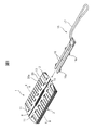
- FIG. 1 is a perspective view of a cleaning member manufactured by an embodiment of the manufacturing method and / or manufacturing system of the present invention and a gripping tool fixed to the cleaning member.
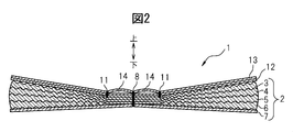
- 2 is a cross-sectional view taken along line XX of FIG.
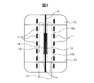
- FIG. 3 is a plan view of the cleaning member shown in FIG. 1.
- FIG. 4 is a schematic view for explaining a method and / or a manufacturing system for manufacturing the cleaning member shown in FIG.
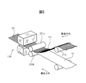
- FIG. 5 is a perspective view for explaining a multilayer web forming step in the production method of the present invention.
- the manufacturing method of the cleaning member by this invention is a manufacturing method which manufactures the cleaning member obtained from the multilayer web formed by superposing
- a fiber bundle conveying step for continuously conveying toward the merged portion to be superposed, a nonwoven fabric conveying step for continuously conveying the belt-shaped nonwoven fabric toward the merged portion, and a fiber bundle conveyed in the fiber bundle conveying step The multilayer web forming step of forming the multilayer web by superimposing the belt-shaped nonwoven fabric transported in the nonwoven fabric transporting step at the junction, and the fiber bundle and the belt-shaped nonwoven fabric in the multilayer web are mutually And a joining step for joining.
- a multilayer web is formed by overlapping with the belt-shaped nonwoven fabric (Aspect 1).
- “with width” in the present invention means a length in a direction orthogonal to the transport direction when a transport target such as a fiber bundle, a strip-shaped nonwoven fabric, or a multilayer web is pulled in the transport direction (length direction). That is, the length in the width direction is reduced.
- the manufacturing method of the cleaning member according to the present invention is a novel manufacturing method that is suitable for manufacturing a cleaning member excellent in cleaning performance and can be manufactured efficiently.
- the cleaning member manufacturing method according to the present invention transports the fiber bundle with a tension that does not allow the fiber bundle to enter the width in the fiber bundle transporting step, and in the multilayer web forming step, the fiber bundle transports the width of the fiber bundle.
- a multi-layer web is formed by overlapping with the belt-shaped nonwoven fabric in a state where a tension that does not enter is applied.
- contracts greatly or is crimped by the reaction of the recovery from width
- the fiber bundle in the fiber bundle conveying step it is preferable to convey the fiber bundle while slackening it in the conveying direction (length direction) (Aspect 2).
- the fiber bundle in the fiber bundle conveying step acts only to the extent of the tension caused by its own weight except when the fiber bundle is moved in the conveying direction. It is possible to stably maintain a state in which the length in the width direction is maintained substantially constant without doing so. Further, it is possible to prevent the fiber bundle from being unnecessarily opened due to the tension.
- tension is applied to the fiber bundle in the transport direction. Even in this case, only a tension that does not allow the fiber bundle to enter the width acts on the fiber bundle.
- the fiber bundle can be prevented from having a width.
- to convey the fiber bundle substantially linearly means to convey the fiber bundle while suppressing meandering of the fiber bundle.
- a certain amount of tension is applied to the fiber bundle when the fiber bundle is moved in the conveyance direction.
- a tension that does not allow the fiber bundle to enter the fiber bundle is applied to the fiber bundle. Therefore, when the fiber bundle is moved in the transport direction, the fiber bundle is linearly appropriate in the transport direction.
- the fiber bundle can be conveyed linearly with the meandering suppressed.
- the belt-shaped nonwoven fabric is transported substantially linearly (aspect 4).
- to convey the belt-shaped nonwoven fabric substantially linearly means to transport the belt-shaped nonwoven fabric to such an extent that the belt-shaped nonwoven fabric does not meander.
- the belt-shaped nonwoven fabric is transported so as not to meander, and the belt-shaped nonwoven fabric is preferably transported while applying a certain amount of tension to the belt-shaped nonwoven fabric, for example, a tension that does not allow the belt-shaped nonwoven fabric to enter. .
- the fiber bundle in any of the aspects, is conveyed with the length in the width direction of the fiber bundle being substantially constant (Aspect 5).
- the fiber bundle in the fiber bundle conveying step, the fiber bundle is conveyed with a tension that does not allow the fiber bundle to enter the width. Therefore, in the fiber bundle conveying step, the fiber bundle has a width. Without entering, it is possible to convey the fiber bundle while keeping the length in the width direction almost constant at all times. As a result, in this fiber bundle conveying step, the progress of fiber bundle opening due to excessive tension acts is suppressed as much as possible, the length of the fiber bundle, the raising condition, etc. are managed, and further, the multilayer Management of the dimensions of the entire web is facilitated.
- the width of the belt-shaped nonwoven fabric in the width direction is substantially constant and the belt-shaped nonwoven fabric is conveyed (Aspect 6).
- the length in the width direction of the belt-like nonwoven fabric is substantially constant means that the width in the width direction of the belt-like nonwoven fabric does not become small, that is, does not enter the width.
- the width of the belt-like nonwoven fabric is eliminated and the width direction length and the conveyance direction (length direction) ) May vary greatly, making it difficult to control and manage the dimensions of the strip-shaped nonwoven fabric. Therefore, according to this aspect 6, since the width of the belt-shaped nonwoven fabric does not occur, even after the tension is released, the variation in the length in the conveyance direction and the length in the width direction is small, and the control of the dimensions of the belt-shaped nonwoven fabric And management, and further management of the dimensions of the entire multi-layer web is facilitated.
- any of the aspects in the bonding step of bonding the fiber bundle and the strip-shaped nonwoven fabric in the multilayer web to each other, these fiber bundles and the strip-shaped nonwoven fabric are bonded to each other. (Aspect 7). In another embodiment, hot melt bonding.
- the fiber bundle is opened (aspect 8).
- the fibers of the fiber bundle are crimped and raised, and the entire fiber bundle is softly spread like cotton. It becomes easy to entangle with.
- the fibers can flexibly contact the object to be cleaned, the object to be cleaned will not be damaged even if the cleaning member is pressed, and furthermore, the corner of the floor or furniture where dust is difficult to remove. Dust can be entangled by allowing fibers to enter a narrow portion such as a corner portion.
- the present invention includes a fiber opening step for opening the fiber bundle used for manufacturing the fiber member before the fiber bundle conveying step.
- a fiber opening step for opening the fiber bundle used for manufacturing the fiber member before the fiber bundle conveying step.
- means such as repeatedly applying and relaxing tension in the conveying direction or blowing air on the fiber bundle to be opened.
- the method further includes a cutting step of cutting the multilayer web in the width direction after the joining step (embodiment 9).
- a system for producing a cleaning member according to the present invention is a system for producing a cleaning member from a multilayer web formed by superimposing a fiber bundle and a belt-like nonwoven fabric, and superimposing the fiber bundle on the belt-like nonwoven fabric.
- a fiber bundle conveying device that continuously conveys toward the merging portion and a non-woven fabric conveying device that continuously conveys the belt-shaped nonwoven fabric toward the merging portion.
- the multilayer web forming device that forms the multilayer web by superimposing the fiber bundles conveyed by the fiber bundle conveying device and the belt-shaped nonwoven fabric conveyed by the nonwoven fabric conveying device at the joining portion; And a joining device that joins the fiber bundle and the strip-shaped nonwoven fabric in the multilayer web to each other.
- the said fiber bundle conveyance apparatus can convey the said fiber bundle with the tension
- the cleaning member manufacturing system according to the present invention is a system that is suitable for manufacturing a cleaning member excellent in cleaning performance and that can be manufactured efficiently.
- the fiber bundle conveying device that continuously conveys the fiber bundle toward the joining portion where the fiber bundle is overlapped with the belt-shaped nonwoven fabric, the fiber bundle is not included in the width of the fiber bundle. It can be conveyed with the tension of.
- the multilayer web forming apparatus for forming the multilayer web by superimposing the fiber bundle conveyed by the fiber bundle conveying device and the belt-shaped nonwoven fabric conveyed by the nonwoven fabric conveying device in the joining portion, A multilayer web can be formed by superimposing the fiber bundle on the belt-shaped nonwoven fabric while applying a tension that does not enter the width. Thereby, even when the tension on the multilayer web is released after the fiber bundle and the strip-shaped nonwoven fabric are joined by the joining device in the joining device, the fiber bundle constituting the multilayer web is contracted or crimped. The length does not change drastically.
- the cleaning member when manufacturing the cleaning member, it is easy to control the length of the fiber bundle, and the length of the fiber bundle relative to the length (width) of the nonwoven fabric can be set to a desired length.
- the fiber bundle is difficult to be cut when being overlapped with the belt-shaped nonwoven fabric in the multilayer web forming apparatus during conveyance, and further, for example, fused when the fiber bundle and the belt-shaped nonwoven fabric are bonded in the bonding device.
- High-speed productivity is excellent because it is difficult to cut (fuse) in some cases.
- the fiber bundle conveying device can convey the fiber bundle while bending the fiber bundle in the length direction (aspect 11).
- the fiber bundle transported by the fiber bundle transport device acts only about the tension caused by its own weight except when moving the fiber bundle in the transport direction
- the length in the width direction of the fiber bundle is It is possible to stably maintain a state in which the length in the width direction is maintained substantially constant without entering the width. Further, it is possible to prevent the fiber bundle from being unnecessarily opened due to the tension.
- aspect 10 it is preferable to further include a cutting device for cutting the multilayer web in the width direction (aspect 12).
- the system for manufacturing the cleaning member according to the present invention can include a device for opening the fiber bundle in order to open the fiber bundle.
- modes 10 to 12 can be combined.
- FIGS. 1 to 5 embodiments of the method and system for manufacturing a cleaning member according to the present invention will be described in more detail with reference to FIGS.
- the method and system for manufacturing the cleaning member according to the present invention are not limited to the embodiment of the present invention shown in FIGS. 1 to 5 within the scope of the object and the gist of the present invention. .
- FIG. 1 is a perspective view of the cleaning member 1 and a gripping tool 15 fixed to the cleaning member 1
- FIG. 2 is a sectional view taken along line XX of FIG. 1
- FIG. 3 is a cleaning shown in FIG. 3 is a plan view of the member 1.
- FIG. 1 “upper” in FIG. 2 may be referred to as the upper side, and “lower” may be referred to as the lower side. However, “upper” and “lower” in FIG. Yes, and does not limit the vertical direction of the cleaning member 1.
- the cleaning member 1 includes a raised portion 2, a base sheet 12 stacked above the raised portion 2, and a holding sheet 13 stacked above the base sheet 12. It has.
- the cleaning member 1 is formed with an insertion portion 14 for inserting the insertion portion 16 of the gripping tool 15 between the base sheet 12 and the holding sheet 13. .
- the cleaning member 1 is formed with two inserted portions 14 so that the inserting portion 16 branched into two can be inserted.
- the number of inserted portions 14 in this embodiment is two, the number of inserted portions 14 can be changed as appropriate according to the number of branches of the inserting portion 16.
- Another embodiment includes an embodiment in which the number of inserted portions 14 is three or more.
- the raised portion 2 includes a first fibrous member 3, a second fibrous member 4 stacked on the lower side of the first fibrous member 3, and a lower portion of the second fibrous member 4.
- a four-layered fibrous member composed of a third fibrous member 5 stacked on the side and a fourth fibrous member 6 stacked on the lower side of the third fibrous member 5, and a fiber of this four-layered structure And a strip sheet 7 stacked on the lower side of the cylindrical member (the lower side of the fourth fibrous member 6).
- the fibrous member of the raised portion 2 in the present embodiment has a four-layer structure, the layer structure of the fibrous member can be changed as appropriate.
- Another embodiment includes an embodiment in which the layer structure of the fibrous member is a one-layer structure, a two-layer structure, or a three-layer structure, and as another embodiment, the layer structure of the fibrous member has five or more layers. Embodiments that are structures are mentioned. Moreover, although the raising part 2 in this embodiment is provided with the strip sheet 7, the presence or absence of the strip sheet 7 can be selected suitably. As another embodiment, an embodiment in which the strip sheet 7 is omitted can be cited.
- the first to fourth fibrous members 3 to 6 are fiber bundles to which an oil agent is attached, and are dusting oil agents (for example, oil agents mainly composed of liquid paraffin) that promote the adsorption of dust, dust and the like. is there.
- dusting oil agents for example, oil agents mainly composed of liquid paraffin
- the fiber bundle is, for example, tow (TOW), preferably opened tow.
- TOW tow
- Tow means a bundle of extremely large numbers of filaments as described in JIS L 0204-3: 1998 3.1.24.
- the fiber bundle may be a bundle of slit fibers (fibers made by cutting and stretching a thin film), split fibers (fibers made by dividing an elongated film into a network structure), and the like.
- the fiber bundle examples include a fiber bundle made of thermoplastic fibers and a fiber bundle containing thermoplastic fibers.
- the raw material of the fiber constituting the fiber bundle include polyethylene, polypropylene, polyethylene terephthalate, nylon, rayon, and the like.
- the fiber constituting the fiber bundle include a single fiber and a composite fiber ( For example, a core-sheath type composite fiber, a side-by-side type composite fiber) and the like can be mentioned.
- the composite fiber is preferably a core-sheath type composite fiber from the viewpoint of heat-fusibility, and more preferably a core-sheath type composite fiber having a melting point of the core higher than that of the sheath.
- Preferable core-sheath type composite fibers include, for example, core-sheath type composite fibers in which the core is made of polypropylene or polyethylene terephthalate and the sheath is made of polyethylene. Further preferable core-sheath type composite fibers include, for example, polyethylene in the core. A core-sheath type composite fiber made of terephthalate and having a sheath made of polyethylene can be mentioned.
- the fineness of the fibers constituting the fiber bundle is preferably 1 to 50 dtex, more preferably 2 to 10 dtex.
- the fiber bundle may include a plurality of types of fibers having the same fineness, or may include a single type or a plurality of types of fibers having different finenesses.
- each fiber constituting the fiber bundle is composed of crimped fibers.
- the fiber bundle can be made bulky, and a structure in which dust, dust, etc. can be easily taken into the crimped portions can be obtained.
- an embodiment in which each fiber constituting the fiber bundle is constituted by non-crimped fibers can be mentioned.
- the strip sheet 7 is formed of a nonwoven fabric made of thermoplastic fibers (heat-fusible fibers), or a nonwoven fabric containing thermoplastic fibers, like the base sheet 12 and the holding sheet 13. 12 is formed in a rectangular shape having substantially the same width and length as those.
- the strip sheet 7 is provided with sawtooth-shaped cuts (not shown) at predetermined intervals over the entire strip sheet 7, and this cut cuts the entire length of both edges in the width direction of the strip sheet 7.
- a strip (not shown) having serrated edges is formed.
- a base sheet 12 and a holding sheet 13 are sequentially stacked on the upper side of the first fibrous member 3 of the raised portion 2, and between the base sheet 12 and the holding sheet 13. A portion to be inserted 14 for inserting the insertion portion 16 of the gripping tool 15 is formed.
- the base sheet 12 and the holding sheet 13 have a rectangular shape, and both the sheets 12 and 13 are set to have the same dimension in the width direction (left and right direction in FIG. 3).
- the length of the base sheet 12 is set to be longer in the length direction (vertical direction in FIG. 3).
- the holding sheet 13 is stacked on the upper side of the base sheet 12 so that both ends of the base sheet 12 in the longitudinal direction protrude outward from the both ends of the holding sheet 13 by a predetermined length.
- the base sheet 12 and the holding sheet 13 are formed of a nonwoven fabric made of thermoplastic fibers (heat-fusible fibers) or a nonwoven fabric containing thermoplastic fibers.
- thermoplastic fiber include polyethylene fiber, polypropylene fiber, polyethylene terephthalate fiber, composite fiber of polyethylene and polyethylene terephthalate, composite fiber of polyethylene and polypropylene, for example, the core is made of polyethylene terephthalate, and the sheath is made of polyethylene. And core-sheath type composite fiber.
- the nonwoven fabric include thermal bond nonwoven fabric, spunbond nonwoven fabric, and spunlace nonwoven fabric.
- Another embodiment includes an embodiment in which the base sheet and the holding sheet are formed from a thermoplastic resin film, for example, a polyethylene film or a polypropylene film, and as yet another embodiment, the base sheet and the holding sheet are The embodiment formed from the laminate sheet of a nonwoven fabric and a resin film is mentioned.
- a thermoplastic resin film for example, a polyethylene film or a polypropylene film
- the base sheet and the holding sheet are The embodiment formed from the laminate sheet of a nonwoven fabric and a resin film is mentioned.
- the base material sheet 12 and the holding sheet 13 are all layers (the first fibrous member 3, the second fibrous member 4, the third fibrous member 5, The fourth fibrous member 6 and the strip sheet 7) are integrally fused.
- the cleaning member 1 has a first melt extending in the longitudinal direction at the center in the width direction. A landing portion 8 is formed.
- the base sheet 12 and the holding sheet 13 are formed on one side (first fiber) of the raised portion 2 by the second fused portion forming device 134 described later on both sides (left and right in FIG. 2) of the first fused portion 8. And is fused integrally with the member 3).
- the cleaning member 1 is formed with two second fusion portions 11 that extend in the longitudinal direction and fuse the base sheet 12, the holding sheet 13, and the first fibrous member 3.
- Each of the two second fusion parts 11 is formed intermittently.
- the raised portion 2 becomes easier to spread.
- the raised portion 2 is likely to come into contact with dust, so that the dust is easily entangled and caught, and as a result, the cleaning efficiency is improved.
- the base sheet 12 and the holding sheet 13 are formed in the first fused portion 8 in the entire layer of the raised portion 2 (first fibrous member 3, second fibrous member 4, third fibrous member 5, fourth fibrous shape.
- the two second fused portions 11 are fused with the first fibrous member 3 of the raised portion 2.
- the base sheet 12 and the holding sheet 13 are partitioned by the first fusion part 8 and the two second fusion parts 11, and the longitudinal direction of the base sheet 12 and the holding sheet 13 is defined.
- a pair of bag-like spaces that are open at both ends in the longitudinal direction are formed, and these spaces serve as the pair of inserted portions 14. Therefore, the insertion portion 16 of the gripping tool 15 can be inserted into the bag-like interior of the pair of inserted portions 14.
- the base sheet 12 and the holding sheet 13 are fused at the center portion of the first fibrous member 3 of the raised portion 2 by a second fused portion forming device 134 described later. That is, as shown in FIG. 3, the cleaning member 1 is formed with a pair of fusion wires 18 at a predetermined interval in the width direction of the base sheet 12 and the holding sheet 13. A first fusion part 8 is formed between the lines 18.
- the pair of fusion lines 18 is a mark for managing the position of the first fusion part 8 in the manufacturing stage, and is the first fusion part 8 disposed between the pair of thermal fusion lines 18? By managing whether or not with a sensor or the like, it is possible to sort out non-defective products and defective products.
- the two second fusion portions 11 are provided intermittently in the longitudinal direction of the base sheet 12 and the holding sheet 13, and the two second fusion portions 11 are provided.
- a plurality of arc-shaped protrusions 16 a provided on the outer side of each insertion portion 16 of the gripping tool 15 can be locked to the non-fused portion of the portion 11. Thereby, each insertion part 16 of the gripping tool 15 is prevented from coming out of each inserted part 14.
- both edge portions in the width direction of the base sheet 12 and the holding sheet 13 are arranged at predetermined intervals along the longitudinal direction.
- a sawtooth-shaped notch 20a is provided, and a plurality of strips 20 having both serrated edges are provided by the notch 20a.
- Another embodiment includes an embodiment in which the base sheet 12 and the holding sheet 13 are not provided with the sawtooth-shaped cuts 20a, and thus the strip pieces 20 are not provided.
- the gripping tool 15 includes a pair of rectangular plate-like insertion portions 16 arranged in parallel to each other, and side surfaces located on the outer sides at both ends in the short direction of each insertion portion 16. It has a pair of protruding arc-shaped projections 16a and a holder portion 17 provided integrally with one end of the insertion portion 16, and is made of, for example, plastic.
- both insertion portions 16 of the gripping tool 15 By inserting both insertion portions 16 of the gripping tool 15 into both insertion portions 14 of the cleaning member 1 and engaging the protrusions 16 a with the non-fused portions of the two second fusion portions 11, the gripping tool 15.
- the cleaning member 1 is attached. Then, by holding the holder portion 17 of the gripping tool 15 and bringing the raised portion 2 into contact with the site to be cleaned and moving it in a desired direction, dust, dust, etc. at the location to be cleaned are captured by the raised portion 2, The part to be cleaned is cleaned.
- the cleaning member shown in FIGS. 1 to 3 is an example of a cleaning member that can be manufactured using the method and system for manufacturing the cleaning member according to the present invention, and the method for manufacturing the cleaning member according to the present invention and
- 2007-135774 No. 2007-209460, No. 2007-209461, No. 2007-029136, No. 2007-111297, No. 2007-135666, No. 2007-136156, No. 2007-136156 2007-159612, 2007-236690, 2008-006260, 2008-119171 and 2007-029135 can be used to manufacture the cleaning member, and refer to these publications. Which is incorporated herein by reference.
- the manufacturing method of the cleaning member of this indication, and the manufacturing system of a cleaning member are US6,554,937B, US2002 / 148061A, US2003 / 000034A, US2004 / 0149095A, US2005 / 0005381A, US2005 / 039285A, US2005 / 097695A, for example.
- FIG. 4 is a schematic view for explaining a method and an apparatus for manufacturing the cleaning member 1.
- a method for manufacturing the cleaning member 1 is performed using the apparatus 100 shown in FIG. 4. .
- the method for manufacturing the cleaning member 1 includes the following step 1 and step 2.
- step 1 The step of opening the fiber bundle to the step of carrying it and the step of carrying the belt-like nonwoven fabric
- Step 2 A multilayer web is manufactured using the fiber bundle, and the cleaning member 1 is cut out from the multilayer web (cut) Process)
- step 1 includes the following step 1a and step 1b.
- Step 1a Step of opening first fiber bundle F1 to fourth fiber bundle F4
- Step 1b Fiber bundle transporting step of transporting first fiber bundle F1 to fourth fiber bundle F4
- Step 1c Non-woven fabric transporting process for transporting the strip-shaped non-woven fabrics 121 and 123 toward the joining portion with the fiber bundle F1.
- the step 1 includes the step 1a, but the presence or absence of the step 1a can be appropriately selected depending on the type of fiber bundle to be used.
- Another embodiment includes an embodiment in which step 1a is omitted. For example, when the fiber bundle is composed of non-crimped fibers, step 1a can be omitted.
- Step 1a Hereinafter, the step 1a will be described by taking the step of opening the first fiber bundle F1 as an example, but the steps of opening the other fiber bundles F2 to F4 are similarly performed.
- the first fiber bundle F1 composed of crimped fibers is continuously drawn out from a storage container (not shown) and sent to the first nip rolls 102a and 102b that rotate at a constant peripheral speed V1.
- the first fiber bundle F1 that has passed through the first nip rolls 102a and 102b passes through the plurality of tension rolls 104 and is sent to the second nip rolls 106a and 106b that rotate at the peripheral speed V2.
- the peripheral speed V2 of the second nip rolls 106a and 106b is faster than the peripheral speed V1 of the first nip rolls 102a and 102b. Due to the difference in peripheral speed, tension is applied to the first fiber bundle F1 between the first nip rolls 102a and 102b and the second nip rolls 106a and 106b, and as a result, the first fiber bundle F1 is Opened.
- Each tension roll 104 is made of, for example, solid steel, and its mass is adjusted so that a considerable amount of force is required for rotation. Therefore, when the first fiber bundle F1 advances from the first nip rolls 102a and 102b toward the second nip rolls 106a and 106b while rotating the tension rolls 104, the rotation speed of each tension roll 104 increases rapidly. This prevents the movement speed of the first fiber bundle F1 from increasing rapidly.
- Each tension roll 104 is disposed so that the stroke between the first nip rolls 102a and 102b and the second nip rolls 106a and 106b becomes long so that the first fiber bundle F1 can be gradually opened. .
- the first fiber bundle F1 that has passed through the second nip rolls 106a and 106b passes through the air supply device 108 and is sent to the third nip rolls 112a and 112b that rotate at the peripheral speed V3.
- the peripheral speed V3 of the third nip rolls 112a and 112b is slower than the peripheral speed V2 of the second nip rolls 106a and 106b. Due to the difference in peripheral speed, the second nip rolls 106a and 106b and the third nip rolls 112a and 112b are more different than between the first nip rolls 102a and 102b and the second nip rolls 106a and 106b.
- the tension of the first fiber bundle F1 is relaxed, and as a result, the first fiber bundle F1 is further opened and the width of the first fiber bundle F1 is widened.
- Air is blown from the air supply unit 108 to the first fiber bundle F1 sent from the second nip rolls 106a and 106b to the third nip rolls 112a and 112b. As a result, the first fiber bundle F1 is further opened. Is done.
- the opening method can be appropriately changed.
- Another embodiment includes an embodiment in which any one of application and relaxation of tension and air blowing is used.
- Embodiments in which other fiber-opening methods are used are mentioned.
- the first to third nip rolls are used for tension application and relaxation, but the number of nip rolls can be changed as appropriate.
- Another embodiment includes an embodiment in which other nip rolls are used in addition to the first to third nip rolls for tension application and relaxation.
- An oil tank 114 is provided on the downstream side in the transport direction from the position of the air supply unit 108 between the second nip rolls 106a and 106b and the third nip rolls 112a and 112b.
- the oil agent in the oil agent tank 114 is transferred and applied to the first fiber bundle F1 sprayed by the transfer roll 110.
- the oil agent contained in the oil agent tank 114 is a dusting oil agent (for example, an oil agent mainly composed of liquid paraffin) that has an effect of promoting adsorption of dust, dust and the like. It is not always necessary to transfer and apply the oil agent in the oil agent tank 114.
- Step 1b the step 1b will be described by taking the fiber bundle conveying step for the first fiber bundle F1 as an example, but the conveying steps for the other fiber bundles F2 to F4 are similarly performed.
- a fiber bundle conveyance device having a conveyance roll provided in (1) is used. Then, the first fiber bundle F1 is conveyed from the third nip rolls 112a and 112b toward the fourth nip rolls 201a and 201b, which are the joining portion 132, via the conveyance rolls.
- the first fiber bundle F1 is conveyed in a relaxed state between the third nip rolls 112a and 112b and the fourth nip rolls 201a and 201b. Further, the transport roll 210 transports while supporting the slack portion of the first fiber bundle F1.
- the slackness of the first fiber bundle is, for example, that the first fiber bundle F1 is made longer than the distance between the third nip rolls 112a and 112b and the fourth nip rolls 201a and 201b. It is formed by feeding out from the nip rolls 112a and 112b in advance.
- the first fiber bundle F1 acts only on its own weight and the minimum tension necessary for conveyance, and the first nip rolls 102a, 102b to the third nip roll 112a. , 112b such as the tension between the fibers 112b is not applied. Therefore, in this fiber bundle conveying step, the first fiber bundle F1 does not enter into the width due to the tension, and the progress of the fiber opening is also suppressed.
- the first fiber bundle F1 is conveyed to the merging portion 132, and the second to fourth fiber bundles F2 to F4 are also conveyed to the merging portions 136, 138, and 140 after passing through the step 1b, respectively. Will be.
- step 1c the belt-shaped nonwoven fabrics 121 and 123 to be overlapped at the merged portion with the fiber bundle that has undergone step 1b are conveyed toward the merged portion.
- the strip-shaped non-woven fabrics 121 and 123 correspond to the base sheet 12 and the holding sheet 13 of the cleaning member 1, respectively, and as a multi-layer web S1 formed by overlapping these strip-shaped non-woven fabrics as described below, Transport to 132.
- the strip-shaped non-woven fabric 121 is continuously unwound from the non-woven fabric roll 120 and includes a plurality of rolls arranged in two upper and lower stages. The roll located in the lower stage is intermittently passed through a dancer roll 124 that swings up and down. Is conveyed.
- the strip-shaped nonwoven fabric 123 is continuously unwound from the nonwoven fabric roll 122, includes a plurality of rolls arranged in two upper and lower stages, and passes through a dancer roll 126 in which the lower roll swings up and down. It is conveyed intermittently.
- “intermittently conveyed” means that the strip-shaped nonwoven fabrics 121 and 123 advance in the conveying direction by a certain distance (for example, approximately the width in the width direction of the cleaning member 1) and stop conveying for a certain time. It means to be transported repeatedly. In this way, by intermittently transporting the strip-shaped nonwoven fabrics 121 and 123, the multilayer web stop time for fusing the components of the multilayer web in the joining step described later can be secured.
- the belt-shaped nonwoven fabrics 121 and 123 form a multilayer web S1 composed of two strip-shaped nonwoven fabrics by a pair of nonwoven fabric nip rolls 129a and 129b for the belt-shaped nonwoven fabric at the junction 128 while maintaining a constant tension.
- a saw-tooth shaped blade (not shown) passes through a gather cutter 130 formed intermittently in the circumferential direction on the surface thereof. Thereby, the notch corresponding to the notch 20a (refer FIG. 1) of the base material sheet 12 and the holding sheet 13 is formed.
- the multilayer web S1 advances to the junction part 132, maintaining a fixed tension
- the step 2 includes the following steps 2a to 2c.
- Step 2a A multi-layer web forming step in which the fiber bundle that has undergone step 1b is overlapped with a strip-shaped non-woven fabric to form a multi-layer web
- Step 2b a bonding step in which the fiber bundle contained in the multi-layer web and the strip-shaped non-woven fabric are bonded 2c
- step 2a the fiber bundle which passed through the process 1b and the strip
- Another embodiment includes an embodiment in which one or two of these strip-shaped nonwoven fabrics are overlapped with the fiber bundles that have undergone step 1b, and as another embodiment, in addition to these strip-shaped nonwoven fabrics, An embodiment in which the belt-shaped nonwoven fabric is overlapped with the fiber bundle that has undergone step 1b is given.
- the stacking order is not particularly limited, but it is preferable to stack the belt-shaped nonwoven fabric so as to be positioned in the outermost layer.
- the strip-shaped nonwoven fabrics 121 and 123 correspond to the base material sheet 12 and the holding sheet 13 of the cleaning member 1, respectively.
- the strip-shaped non-woven fabric 121 is continuously unwound from the non-woven fabric roll 120 and includes a plurality of rolls arranged in two upper and lower stages. The roll located in the lower stage is intermittently passed through a dancer roll 124 that swings up and down. Is conveyed.
- the strip-shaped nonwoven fabric 123 is continuously unwound from the nonwoven fabric roll 122, includes a plurality of rolls arranged in two upper and lower stages, and passes through a dancer roll 126 in which the lower roll swings up and down. It is conveyed intermittently.
- intermittently conveyed means that the strip-shaped nonwoven fabrics 121 and 123 advance in the conveying direction by a certain distance (for example, approximately the width in the width direction of the cleaning member 1) and stop conveying for a certain time. It means to be transported repeatedly.
- belt-shaped nonwoven fabric 121,123 is intermittently conveyed, The time for fuse
- the belt-like nonwoven fabrics 121 and 123 form a multilayer web S1 composed of two belt-like nonwoven fabrics by a pair of nip rolls at the joining portion 128 while maintaining a constant tension, and the multilayer web S1 is a sawtooth blade (not shown). Passes through a gather cutter 130 formed intermittently in the circumferential direction on the surface. Thereby, the notch corresponding to the notch 20a (refer FIG. 1) of the base material sheet 12 and the holding sheet 13 is formed. And the multilayer web S1 advances to the junction part 132, maintaining a fixed tension
- the multilayer web S1 merges with the first fiber bundle F1 that has undergone step 1 and is not subjected to tension at the merge section 132.
- the multilayer web S2 is formed by overlapping the multilayer web S1 and the first fiber bundle F1.
- the multilayer web forming apparatus that forms the multilayer web S2 is the fourth nip rolls 201a and 201b that superimpose the multilayer belt-shaped nonwoven fabric that is the multilayer web S1 and the first fiber bundle F1, A gap between the rolls of the fourth nip rolls 201a and 201b is substantially a junction point 132.
- FIG. 5 shows a stack of the first fiber bundle F1 conveyed by the fiber bundle conveying step and the multilayer web S1 formed by the strip-shaped nonwoven fabrics 121 and 123 and conveyed by the nonwoven fabric conveying step.
- the state in the multilayer web formation process to form is shown.
- the first fiber bundle F1 transported in the fiber bundle transporting process is formed upstream of the fourth nip rolls 201a and 201b, which are the junction 132, that is, the multilayer web S2. Before, it is conveyed in a slack state to some extent.
- the multilayer web S1 (band-shaped nonwoven fabric) conveyed by the nonwoven fabric conveying step is conveyed to the junction 132 in a state where a tension that does not sag and does not enter the width is applied. Furthermore, after the first fiber bundle F1 and the multilayer web S1 are overlapped by the fourth nip rolls 201a and 201b to form the multilayer web S2, the slackness of the fiber bundle is eliminated. The acting tension is maintained at such a level that it still does not fall. Moreover, the magnitude
- the multi-layer web S2 composed of the first fiber bundle F1 and the multi-layer web S1 is a device relating to the subsequent joining process in a state where a tension that does not allow for the insertion of the width is applied as a whole. It will be conveyed to the forming apparatus 134.
- the tension that does not enter the width is maintained even after the multilayer web S2 is formed, while maintaining the tension that does not enter the width due to the slack, before the multilayer web S2 is formed.
- the opening of the first fiber bundle F1 is suppressed during and after the formation, and the length of the first fiber bundle F1 can be easily controlled.
- a large tension is applied so that the fiber spreads as much as it is loosened. Is deterred.
- the multilayer web S2 is temporarily secured to secure the fusion time. Accordingly, the transport of the first fiber bundle F1 is also temporarily stopped. However, the first fiber bundle is stopped because there is no problem even if slack is formed by the stop of the transport. Sufficient time can be secured. Therefore, it is possible to secure a time for joining while maintaining a tension that does not enter the width.
- the multilayer web S2 is sequentially joined with the second fiber bundle F2 to the fourth fiber bundle F4 that have passed through the process 1 at the joining portions 136, 138, and 140, and the second fiber bundle F2 to the second fiber bundle F2 is joined to the multilayer web S2.
- the four fiber bundles F4 are sequentially overlapped to form the multilayer web S3.
- in the junction part 136,138,140 with respect to the multilayer web S2 by each of a pair of nip roll 202a, 202b, 203a, 203b, 204a, 202b as a multilayer web formation apparatus.
- the second fiber bundle F2 to the fourth fiber bundle F4 are sequentially overlapped to form the multilayer web S3.
- the belt-shaped nonwoven fabric 151 corresponding to the strip sheet 7 of the cleaning member 1 is overlapped with the multilayer web S3 at the junction 156, separately from the belt-shaped nonwoven fabric 121 and 123 described above.
- a multilayer web S4 is formed.
- the strip-shaped nonwoven fabric 151 is transported by a nonwoven fabric transport device formed by various rolls in the nonwoven fabric transport process for the strip-shaped nonwoven fabric 151. That is, in the nonwoven fabric conveyance process for the strip-shaped nonwoven fabric 151, it is continuously unwound from the nonwoven fabric roll 150, is intermittently conveyed by passing through the dancer roll 152, and passes through the gather cutter 154.
- the gather cutter 154 has a saw-tooth shaped blade (not shown) continuous in the circumferential direction on the surface thereof, so that a saw-tooth-like cut (not shown) is formed in the strip-shaped nonwoven fabric 151 that has passed the gather cutter 154. It is formed. And the strip
- the multilayer web S2 passes through the second fusion part forming device 134 as a joining device used in the joining step before joining the second fiber bundle F2 to the fourth fiber bundle F4.
- the second fusion part forming device 134 fuses the strip-shaped nonwoven fabrics 121 and 123 and the first fiber bundle F1 included in the multilayer web S2 to form two second fusion parts 11 (see FIG. 3). To do. Thereby, the multilayer web S2 is melt
- a heat seal device is used as the second fusion part forming device 134, but other seal devices (for example, an ultrasonic seal device or the like) may be used.
- the multilayer web S4 passes through a first fusion part forming device 158 as a joining device.
- the first fusion part forming device 158 fuses the entire multilayer web S4 to form the first fusion part 8 (see FIG. 3 and the like) on the multilayer web S4. Thereby, the multilayer web S4 is fused over the thickness direction.
- a heat seal device is used as the first fusion part forming device 154, but the fusion part forming device can be appropriately changed.
- Another embodiment includes an embodiment in which an ultrasonic sealing device is used.
- step 2c The multilayer web S4 that has passed through the first fusion part forming device 158 is cut in the width direction of the multilayer web S4 by the cutting device 160 provided with a cutter, whereby the individual cleaning members 1 are cut out.
- the cleaning member 1 manufactured according to the present embodiment includes the strip sheet 7, but the cleaning member manufactured according to another embodiment does not include the strip sheet 7. Moreover, in the cleaning member 1 manufactured by this embodiment, although the to-be-inserted part 14 is located in the surface of the cleaning member 1, the cleaning member manufactured by another embodiment is the base material sheet 12 and the holding sheet 13. And the fibrous members 3 to 6 are changed in the stacking order, the inserted portion 14 is disposed between any of the adjacent fibrous members 3 to 6. Thereby, it can clean using both surfaces of the cleaning member 1.
- FIG. At this time, in order to facilitate the insertion of the insertion portion 16 into the insertion portion 14, the length of the base sheet 12 and the holding sheet 13 in the longitudinal direction (vertical direction in FIG. 3) is determined from the fibrous members 3-6. It is preferable to make the length longer, and these dimensions can be arbitrarily determined. At this time, the strip sheet 7 may or may not be used, and the strip sheet 7 may be disposed on both surfaces of the cleaning member 1.
- 2013-002855 filed in Japan on January 10, 2013 and a US application claiming priority thereof, ie, US Patent Application No. 13 / 749,717, and (13) Japanese Patent Application No. 2013-002857 filed in Japan on January 10, 2013, and US application claiming priority thereof, ie, US Patent Application No. 13 / 749,715.
Landscapes
- Cleaning Implements For Floors, Carpets, Furniture, Walls, And The Like (AREA)
- Laminated Bodies (AREA)
- Nonwoven Fabrics (AREA)
Abstract
Priority Applications (2)
| Application Number | Priority Date | Filing Date | Title |
|---|---|---|---|
| US14/655,939 US9919501B2 (en) | 2012-12-29 | 2013-12-27 | Manufacturing method and manufacturing system for cleaning member |
| JP2014554616A JP6116590B2 (ja) | 2012-12-29 | 2013-12-27 | 清掃部材の製造方法及び製造システム |
Applications Claiming Priority (2)
| Application Number | Priority Date | Filing Date | Title |
|---|---|---|---|
| JP2012289184 | 2012-12-29 | ||
| JP2012-289184 | 2012-12-29 |
Publications (1)
| Publication Number | Publication Date |
|---|---|
| WO2014104351A1 true WO2014104351A1 (fr) | 2014-07-03 |
Family
ID=51017830
Family Applications (1)
| Application Number | Title | Priority Date | Filing Date |
|---|---|---|---|
| PCT/JP2013/085233 Ceased WO2014104351A1 (fr) | 2012-12-29 | 2013-12-27 | Procédé de fabrication et système de fabrication pour élément de nettoyage |
Country Status (3)
| Country | Link |
|---|---|
| US (2) | US20140187406A1 (fr) |
| JP (1) | JP6116590B2 (fr) |
| WO (1) | WO2014104351A1 (fr) |
Families Citing this family (11)
| Publication number | Priority date | Publication date | Assignee | Title |
|---|---|---|---|---|
| US20140187406A1 (en) * | 2012-12-29 | 2014-07-03 | Unicharm Corporation | Method of producing cleaning member |
| WO2014104325A1 (fr) | 2012-12-29 | 2014-07-03 | ユニ・チャーム株式会社 | Procédé et système de production d'élément de nettoyage |
| JP6047401B2 (ja) | 2012-12-29 | 2016-12-21 | ユニ・チャーム株式会社 | 開繊された繊維束の製造方法、清掃部材の製造方法、繊維束の開繊装置、及び清掃部材の製造システム |
| US20140182767A1 (en) | 2012-12-29 | 2014-07-03 | Unicharm Corporation | Method of producing cleaning member |
| US11375867B2 (en) | 2018-04-03 | 2022-07-05 | The Procter & Gamble Company | Cleaning article with differential sized tow tufts |
| US11903542B2 (en) * | 2018-04-03 | 2024-02-20 | The Procter & Gamble Company | Cleaning article with double bonded tow tufts |
| US12082760B2 (en) * | 2018-04-03 | 2024-09-10 | The Procter & Gamble Company | Cleaning article with irregularly spaced tow tufts |
| CN112871805A (zh) * | 2021-01-14 | 2021-06-01 | 柳昌兵 | 一种用于熔喷布生产的切分机构 |
| CN114803629B (zh) * | 2022-04-26 | 2023-11-28 | 郴州加宁科技有限公司 | 一种感应加热透热设备的可调双压辊进料装置 |
| EP4349233B1 (fr) * | 2022-10-06 | 2025-08-13 | The Procter & Gamble Company | Procédé d'emballage d'une lingette nettoyante |
| EP4349230A1 (fr) | 2022-10-06 | 2024-04-10 | The Procter & Gamble Company | Chiffon de nettoyage |
Citations (5)
| Publication number | Priority date | Publication date | Assignee | Title |
|---|---|---|---|---|
| JP2000296083A (ja) * | 1999-04-13 | 2000-10-24 | Uni Charm Corp | 使い捨ての汚れ拭き取り用具の製造方法 |
| JP2001288639A (ja) * | 2000-04-04 | 2001-10-19 | Mitsubishi Rayon Co Ltd | 強化繊維束の開繊方法及びプリプレグ製造方法 |
| WO2007023965A1 (fr) * | 2005-08-25 | 2007-03-01 | Daio Paper Corporation | Procede de fabrication d’un article absorbant et article absorbant |
| JP2007283086A (ja) * | 2006-03-23 | 2007-11-01 | Kao Corp | 吸収体及びその製造方法 |
| JP2008006260A (ja) * | 2006-06-01 | 2008-01-17 | Kao Corp | 清掃用物品並びにその起毛方法及びその製造方法 |
Family Cites Families (151)
| Publication number | Priority date | Publication date | Assignee | Title |
|---|---|---|---|---|
| US2733064A (en) | 1956-01-31 | martin | ||
| US470898A (en) | 1892-03-15 | William reiffel | ||
| US345644A (en) | 1886-07-13 | Willett w | ||
| US1847065A (en) | 1927-05-24 | 1932-02-23 | Champion Coated Paper Company | Process and apparatus for applying solutions |
| US1989048A (en) | 1934-05-25 | 1935-01-22 | Us Paper Mills Inc | Method and apparatus for reducing the bulk of stacks of paper sheets and softening said sheets |
| US2738973A (en) | 1953-01-27 | 1956-03-20 | Roland Offsetmaschf | Stacking device for machines working on sheets, particularly printing machines |
| US2836418A (en) | 1953-05-22 | 1958-05-27 | Roland Offsetmaschf | Stacking device for printing machines |
| US2737688A (en) | 1953-05-25 | 1956-03-13 | Eastman Kodak Co | Tow opening device |
| US2748426A (en) | 1953-06-12 | 1956-06-05 | Turbo Machine Co | Apparatus for producing staple fibers |
| US2926392A (en) | 1954-01-11 | 1960-03-01 | Eastman Kodak Co | Method and apparatus for opening crimped tow |
| US2828752A (en) | 1954-08-16 | 1958-04-01 | Eastman Kodak Co | Fibrous tobacco smoke filters |
| US3017309A (en) | 1957-02-21 | 1962-01-16 | Eastman Kodak Co | Method for the manufacture of filters composed of cellulose acetate |
| US2904335A (en) | 1958-03-04 | 1959-09-15 | Rabinow Jacob | Stacker for mail sorters and the like |
| US2960023A (en) | 1958-04-25 | 1960-11-15 | Kimberly Clark Co | Papermaking machine |
| US3022999A (en) | 1959-05-25 | 1962-02-27 | Lamb Grays Harbor Co Inc | Spring loaded pivoted forward stop for paper stacking mechanism |
| US3120692A (en) | 1960-06-17 | 1964-02-11 | Eastman Kodak Co | Process for the manufacture of uniformly crimped filter tow |
| US3095343A (en) | 1960-09-15 | 1963-06-25 | United States Filter Corp | Method for treating continuous filamentary tows |
| US3218675A (en) | 1963-06-27 | 1965-11-23 | Du Pont | Apparatus for crimping fibers |
| US3417560A (en) | 1963-11-21 | 1968-12-24 | Celanese Corp | Method and apparatus for producing a semi-continuous filament yarn |
| US3362707A (en) | 1964-11-27 | 1968-01-09 | Ahlstroem Oy | Auxiliary stack holder |
| US3376609A (en) | 1965-07-16 | 1968-04-09 | Johnson & Johnson | Method for spreading tows of continuous filaments into sheets |
| US3370848A (en) | 1965-11-22 | 1968-02-27 | Bethlehem Steel Corp | Apparatus for piling sheets |
| US3468096A (en) | 1966-02-08 | 1969-09-23 | Procter & Gamble | Method of interposing a washing compound between superposed layers of nonwoven fibrous material and sealing said layers |
| DE1660266C3 (de) | 1966-03-02 | 1974-11-14 | Deutsche Rhodiaceta Ag, 7800 Freiburg | Verfahren und Vorrichtung zum Ausbreiten und Auflockern eines endlosen, laufenden Fadenbündels durch Anblasen mit einem Strömungsmittel |
| US3608024A (en) | 1967-02-09 | 1971-09-21 | Polymer Processing Res Inst | Method for producing crimped conjugated split fiber |
| US3469285A (en) | 1967-10-23 | 1969-09-30 | Du Pont | Apparatus and process for stretch breaking filamentary tow |
| US3592371A (en) | 1969-06-23 | 1971-07-13 | Turbo Machine Co | Band width controller |
| FR2096953B1 (fr) | 1970-07-10 | 1974-03-22 | Rhodiaceta | |
| NL172468C (nl) | 1970-10-15 | 1983-09-01 | Rhone Poulenc Textile | Werkwijze en inrichting voor het textureren van garen door opeenhopen en samenpersen in een stuwkamer. |
| US3724037A (en) | 1971-05-10 | 1973-04-03 | Tmm Research Ltd | Processes and apparatus for crimping synthetic filamentary materials |
| FR2148729A5 (fr) | 1971-07-30 | 1973-03-23 | Inst Textile De France | |
| JPS521407B2 (fr) | 1972-03-01 | 1977-01-14 | ||
| US3912258A (en) | 1972-07-28 | 1975-10-14 | Merrill David Martin | Conveyor system for conveying sheets |
| US3860127A (en) | 1973-10-15 | 1975-01-14 | Pitney Bowes Inc | Offset stacking mechanism |
| US3907128A (en) | 1973-12-13 | 1975-09-23 | Ppg Industries Inc | Lead edge stop device |
| US3996196A (en) | 1974-10-11 | 1976-12-07 | University Of Notre Dame Du Lac | Polyimide-metallo-phthalocyanines and their preparation |
| US4075375A (en) | 1976-01-30 | 1978-02-21 | Duskin Franchise Co. Ltd. | Cleaning material and process for preparation thereof |
| CH599025A5 (fr) | 1976-04-23 | 1978-05-12 | Grapha Holding Ag | |
| US4190241A (en) | 1978-05-01 | 1980-02-26 | Kimberly-Clark Corporation | Apparatus for converting paper rolls into stacks of individual folded paper sheets |
| DD141151A1 (de) | 1979-02-01 | 1980-04-16 | Hartmut Nagel | Geradstosser zum seitlichen ausrichten von bogen in bogenauslegern |
| JPS56169873A (en) | 1980-06-01 | 1981-12-26 | Koyo Senshiyoku Kk | Production of two layered blanket |
| US4514128A (en) | 1982-07-12 | 1985-04-30 | Mailroom Systems, Inc. | Signature stacker including improved intercept means |
| JPS61105364U (fr) | 1984-12-14 | 1986-07-04 | ||
| NL8500545A (nl) | 1985-02-27 | 1986-09-16 | Oce Nederland B V Patents And | Inrichting voor het verzamelen van bladen. |
| US4640161A (en) | 1985-05-31 | 1987-02-03 | Kurk Robert L | Wood cutting apparatus |
| US5241731A (en) | 1987-03-03 | 1993-09-07 | Concordia Mfg. Co., Inc. | Apparatus for commingling continuous multifilament yarns |
| US4817483A (en) | 1987-07-08 | 1989-04-04 | Armbruster Joseph M | Electrically powered dispenser for rolled sheet material having a rotary blade cutter |
| US5230764A (en) | 1987-10-13 | 1993-07-27 | Philipp Moll | Process and device for producing garments or individual parts thereof |
| US4961805A (en) | 1988-07-25 | 1990-10-09 | Com-Pac International, Inc. | A method for severing and sealing sections of material |
| JPH0333222A (ja) | 1989-06-29 | 1991-02-13 | Tonen Corp | 炭素繊維開繊ローラ |
| DE3923474C2 (de) | 1989-07-15 | 2000-05-04 | Leybold Ag | Elektrischer Umschalter |
| US5168786A (en) | 1990-04-06 | 1992-12-08 | Monarch Marking Systems, Inc. | Cutting apparatus |
| US5060351B1 (en) | 1990-06-04 | 1994-06-07 | Burnett & Co Wm T | Process and apparatus for blowing continuous filament tow |
| JPH04289100A (ja) | 1991-03-18 | 1992-10-14 | Fujitsu Ltd | ペーパカッタ |
| JPH0520896U (ja) | 1991-08-30 | 1993-03-19 | いすゞ自動車株式会社 | 繊維マツト等の切断用治具 |
| CA2069839A1 (fr) | 1991-12-13 | 1993-06-14 | Charles W. Colman | Supports non tisses enrobes et methode d'enduction en bain a concentration elevee et avec faible quantite de liquide absorbe |
| US5253762A (en) | 1992-02-06 | 1993-10-19 | Arr-Tech Manufacturing, Inc. | Stacking, counting and sorting device for flexible, planar food products |
| CH687324A5 (fr) | 1992-02-10 | 1996-11-15 | Bobst Sa | Cadre de support momentané d'un élément en plaque horizontal au sein d'une machine. |
| US5309828A (en) | 1992-02-21 | 1994-05-10 | Merry Wayne M | Method of compacting flat, stacked non-woven articles |
| EP0561069B2 (fr) | 1992-03-18 | 2000-04-05 | Matsushita Electric Industrial Co., Ltd. | Méthode pour l'empilement et le transfert des plaques pour accumulateurs au plomb et dispositif |
| JP3142956B2 (ja) | 1992-05-25 | 2001-03-07 | 東亜ストリング株式会社 | はりす |
| US5243890A (en) | 1992-11-03 | 1993-09-14 | Frank Ober | Cutter assembly |
| US5332210A (en) | 1992-11-18 | 1994-07-26 | Pitney Bowes Inc. | Variable size envelope drop stacker having means for assuring envelope sealing |
| US5355567A (en) | 1992-12-18 | 1994-10-18 | Hoechst Celanese Corporation | Process for preparing engineered fiber blend |
| JP3386533B2 (ja) | 1993-11-12 | 2003-03-17 | 理想科学工業株式会社 | 薄葉体積載受容装置 |
| US5535576A (en) | 1994-07-28 | 1996-07-16 | B & T Sales Ltd. | Apparatus for stacking and loading sheet articles |
| JP3438791B2 (ja) | 1994-08-02 | 2003-08-18 | 東洋紡績株式会社 | カーペットのパイル糸用紡績糸及びカットパイルカーペットの製造方法 |
| JPH09111644A (ja) | 1995-10-20 | 1997-04-28 | Toray Ind Inc | 繊維シートの製造方法および装置 |
| JPH10110346A (ja) | 1996-10-04 | 1998-04-28 | Mitsubishi Chem Corp | ストランドの開繊方法および開繊装置 |
| JPH10266012A (ja) | 1997-03-27 | 1998-10-06 | Teijin Ltd | ポリエステル繊維の製造方法 |
| FR2761380B1 (fr) | 1997-03-28 | 1999-07-02 | Europ Propulsion | Procede et machine pour la realisation de nappes fibreuses multiaxiales |
| US5779432A (en) | 1997-06-18 | 1998-07-14 | Sam Hausman Meat Packer, Inc. | Compact product stacker |
| JPH11323718A (ja) | 1998-05-01 | 1999-11-26 | Toray Ind Inc | ローラ給油装置 |
| US6286403B1 (en) | 1999-04-22 | 2001-09-11 | Rosenthal Manufacturing Co., Inc. | Cutting machine |
| ATE272479T1 (de) | 2000-01-12 | 2004-08-15 | Toray Industries | Produktionsvorrichtung und -methode für geöffnetes faserbündel und prepreg- produktionsmethode |
| JP3927748B2 (ja) | 2000-01-19 | 2007-06-13 | ユニ・チャーム株式会社 | 繊維シートのヒートシール方法およびヒートシール装置 |
| US6494450B2 (en) | 2000-01-31 | 2002-12-17 | Riso Kagaku Corporation | Paper discharge base of image forming apparatus |
| JP3520323B2 (ja) | 2000-03-03 | 2004-04-19 | 株式会社ケーエム裁断機 | 裁断機 |
| US6672585B2 (en) | 2000-06-02 | 2004-01-06 | Fuji Photo Film Co., Ltd. | Apparatus for stacking sheet members, apparatus for measuring dimensions of sheet members, and apparatus for and method of marking sheet members |
| CN1184922C (zh) | 2000-07-10 | 2005-01-19 | 尤妮佳股份有限公司 | 清扫物品 |
| JP2002066991A (ja) | 2000-08-31 | 2002-03-05 | Canon Inc | 切断装置 |
| JP3678637B2 (ja) | 2000-09-01 | 2005-08-03 | ユニ・チャーム株式会社 | 連続フィラメントの開繊方法および開繊装置 |
| US6491492B1 (en) | 2000-10-06 | 2002-12-10 | Longford Equipment International Limited | Batch sheet feeder |
| US6572101B2 (en) | 2001-03-01 | 2003-06-03 | Heidelberger Druckmaschinen Ag | Flexible jogger for a signature feeder |
| JP4132730B2 (ja) | 2001-06-14 | 2008-08-13 | ユニ・チャーム株式会社 | 清掃用製品 |
| FR2826672B1 (fr) | 2001-06-29 | 2003-09-26 | Snecma Moteurs | Procede et dispositif pour realiser une nappe fibreuse par etalement de cables |
| JP2003159752A (ja) | 2001-11-27 | 2003-06-03 | Ykk Corp | 高周波又は超音波加熱による合成樹脂体の溶着方法とその溶着装置 |
| US6627024B2 (en) | 2002-01-07 | 2003-09-30 | Owens Corning Fiberglas Technology, Inc. | Method and apparatus for splicing fibrous mats |
| JP3616067B2 (ja) | 2002-04-02 | 2005-02-02 | 三菱レイヨン株式会社 | 繊維トウの繋ぎ部分検出センサー及び同センサーを用いた制御方法 |
| JP2004238615A (ja) * | 2003-01-16 | 2004-08-26 | Toray Ind Inc | 一方向性プリプレグ、強化繊維シートの製造方法および製造装置 |
| JP4338982B2 (ja) | 2003-01-27 | 2009-10-07 | ユニ・チャーム株式会社 | ロータリーカッターおよびこれを用いた繊維製品の製造方法 |
| CN101818397B (zh) | 2003-07-08 | 2011-10-12 | 福井县 | 制造分散的复丝束的方法和所应用的设备 |
| US6877740B2 (en) | 2003-07-30 | 2005-04-12 | C.G. Bretting Manufacturing Company, Inc. | Starwheel feed apparatus and method |
| US7107659B2 (en) | 2003-09-26 | 2006-09-19 | Celanese Acetate, Llc | Method and apparatus for making an absorbent composite |
| US7673549B2 (en) | 2003-12-03 | 2010-03-09 | H&S Tool, Inc. | Friction linear guide rail assembly for boiler tube cutting apparatus |
| JP2005162461A (ja) | 2003-12-05 | 2005-06-23 | Tohoku Ricoh Co Ltd | 排紙収納装置 |
| US20050139513A1 (en) | 2003-12-30 | 2005-06-30 | Chevron U.S.A. Inc. | Hydroisomerization processes using pre-sulfided catalysts |
| US7156011B2 (en) | 2004-02-25 | 2007-01-02 | The Boeing Company | Depth limiting safeguard for channel machining |
| US7617751B2 (en) | 2004-03-23 | 2009-11-17 | L&P Property Management Company | Quilted fabric panel cutter |
| JP4547994B2 (ja) | 2004-06-02 | 2010-09-22 | 救急薬品工業株式会社 | 塊状物質含有積層フィルム状の可食性口腔内投与剤の製造方法および塊状物質含有積層フィルム状の可食性口腔内投与剤 |
| US20060005675A1 (en) | 2004-07-06 | 2006-01-12 | Scheffer, Inc. | Process of using a fixed size rotary cutter to cut products of variable repeat lengths |
| JP4021893B2 (ja) | 2004-09-09 | 2007-12-12 | ユニ・チャーム株式会社 | 掃除用具 |
| JP4660179B2 (ja) | 2004-12-10 | 2011-03-30 | ユニ・チャーム株式会社 | 掃除用具 |
| JP4688455B2 (ja) | 2004-09-09 | 2011-05-25 | ユニ・チャーム株式会社 | 掃除用具 |
| JP4785369B2 (ja) | 2004-11-16 | 2011-10-05 | ユニ・チャーム株式会社 | 清掃用物品 |
| JP4519620B2 (ja) | 2004-11-29 | 2010-08-04 | 大王製紙株式会社 | トウの加工設備 |
| US20060156876A1 (en) | 2005-01-19 | 2006-07-20 | Pitney Bowes Incorporated | Motion control system and method for a high speed inserter input |
| JP3683266B1 (ja) | 2005-03-14 | 2005-08-17 | ユニ・チャーム株式会社 | 清掃用物品 |
| JP4564870B2 (ja) | 2005-03-23 | 2010-10-20 | 大王製紙株式会社 | トウの開繊設備 |
| JP4785590B2 (ja) | 2005-05-27 | 2011-10-05 | 花王株式会社 | トウの開繊方法 |
| JP4549250B2 (ja) | 2005-07-22 | 2010-09-22 | 花王株式会社 | 清掃用物品 |
| US20070068353A1 (en) | 2005-09-26 | 2007-03-29 | Sealed Air Corporation | Machine for severing a web |
| JP4817998B2 (ja) | 2005-10-19 | 2011-11-16 | 花王株式会社 | 清掃具 |
| ES2388746T3 (es) | 2005-10-19 | 2012-10-18 | Kao Corporation | Utensilio de limpieza |
| JP4657075B2 (ja) | 2005-10-21 | 2011-03-23 | 花王株式会社 | 清掃用物品 |
| DE102005052660B3 (de) | 2005-11-04 | 2007-04-26 | Karl Mayer Malimo Textilmaschinenfabrik Gmbh | Vorrichtung und Verfahren zum Ausbreiten eines Karbonfaserstrangs |
| US7827650B2 (en) | 2005-11-12 | 2010-11-09 | First Quality Retail Services, Llc | Disposable cleaning pad |
| JP4675218B2 (ja) | 2005-11-15 | 2011-04-20 | 花王株式会社 | 清掃用物品及びその製造方法 |
| JP4741934B2 (ja) | 2005-11-16 | 2011-08-10 | ユニ・チャーム株式会社 | 清掃部材、把持具付き清掃部材、及び、清掃部材の製造方法 |
| JP4545086B2 (ja) | 2005-12-09 | 2010-09-15 | 花王株式会社 | 清掃用物品 |
| JP4597880B2 (ja) | 2006-02-08 | 2010-12-15 | ユニ・チャーム株式会社 | 清掃体及び清掃用具 |
| JP4845525B2 (ja) | 2006-02-08 | 2011-12-28 | ユニ・チャーム株式会社 | 清掃体及び清掃用具 |
| ES2397856T3 (es) | 2006-03-09 | 2013-03-11 | Kao Corporation | Artículo de limpieza y método de producción |
| CN101404970B (zh) | 2006-03-23 | 2012-12-12 | 花王株式会社 | 吸收体及其制造方法 |
| US8707838B2 (en) | 2006-08-19 | 2014-04-29 | Dienes Corporation—USA | Cutting arrangement having a tip-to-tip blade arrangement |
| JP5062777B2 (ja) | 2006-10-25 | 2012-10-31 | フォトバ インターナショナル S.R.L. | ローラに巻回した紙及び他の画像印刷物を自動で誤差修正をしながら直交する2軸で同時に切断する自動切断方法 |
| JP4878988B2 (ja) | 2006-11-10 | 2012-02-15 | 花王株式会社 | 清掃用物品の製造方法 |
| JP4919774B2 (ja) | 2006-11-17 | 2012-04-18 | 花王株式会社 | 吸収体 |
| US8448335B2 (en) | 2006-12-19 | 2013-05-28 | Volvo Aero Corporation | Method of manufacturing a wall structure and a machining tool |
| JP5314432B2 (ja) | 2007-02-13 | 2013-10-16 | 大作 山田 | 清掃用シート |
| JP2008297677A (ja) | 2007-06-01 | 2008-12-11 | Toyota Industries Corp | 紡機における繊維束案内装置 |
| JP5007219B2 (ja) | 2007-12-27 | 2012-08-22 | 花王株式会社 | 清掃用シート |
| US8225453B2 (en) | 2007-12-28 | 2012-07-24 | Kikuo Yamada | Cleaning sheet |
| US20090196538A1 (en) | 2008-02-04 | 2009-08-06 | Pzung-Cheng Liou | Linear Guideway with a Negative Pressure Type Dust Absorption Structure |
| JP5231854B2 (ja) | 2008-04-16 | 2013-07-10 | 花王株式会社 | 清掃用シート及びその製造方法 |
| MY175164A (en) | 2008-04-16 | 2020-06-11 | Kao Corp | Cleaning sheet and process for producing the same |
| JP5141415B2 (ja) | 2008-07-18 | 2013-02-13 | 東レ株式会社 | ポリエステル捲縮マルチフィラメントおよびその製造方法 |
| WO2010023836A1 (fr) | 2008-08-28 | 2010-03-04 | Thk株式会社 | Plaque de joint pour dispositif de guidage de mouvement |
| US20100058907A1 (en) | 2008-09-05 | 2010-03-11 | Kern International, Inc. | Apparatus for guiding and cutting web products and related methods |
| US8100038B2 (en) | 2008-11-19 | 2012-01-24 | Goss International Americas, Inc. | Folder for adjustably tensioning a web and method of adjusting web tension as a web is cut |
| CN102246072A (zh) | 2008-12-11 | 2011-11-16 | 托德光学引擎两合公司 | 剥除纤维束纤维的方法与装置 |
| US8201429B1 (en) | 2009-02-03 | 2012-06-19 | Braner Usa, Inc. | Blanking line using slitter as feeder |
| JP5326170B2 (ja) | 2009-05-25 | 2013-10-30 | 福井県 | 繊維束の開繊方法及び開繊糸シート並びに繊維補強シートの製造方法 |
| JP5517536B2 (ja) | 2009-09-18 | 2014-06-11 | ユニ・チャーム株式会社 | 裁断装置 |
| JP5475390B2 (ja) | 2009-10-16 | 2014-04-16 | 花王株式会社 | ヒートシール装置 |
| JP5370082B2 (ja) | 2009-10-29 | 2013-12-18 | 日本精工株式会社 | 直動案内装置 |
| CA2798216C (fr) | 2010-05-11 | 2017-10-31 | Cytec Technology Corp. | Appareil et procedes d'etalement de faisceaux de fibres pour la production continue de pre-impregne |
| KR20110137660A (ko) | 2010-06-17 | 2011-12-23 | 주식회사 성광이엔지 | 롤 컷 리버스 코팅 시스템 |
| JP2012115783A (ja) | 2010-12-02 | 2012-06-21 | Toray Ind Inc | 連続発酵用分離膜モジュールの洗浄方法および連続発酵用膜分離装置 |
| US20140187406A1 (en) * | 2012-12-29 | 2014-07-03 | Unicharm Corporation | Method of producing cleaning member |
| JP6073128B2 (ja) | 2012-12-29 | 2017-02-01 | ユニ・チャーム株式会社 | 切断装置及び切断装置を用いた清掃部材の製造方法 |
-
2013
- 2013-01-25 US US13/749,725 patent/US20140187406A1/en not_active Abandoned
- 2013-12-27 WO PCT/JP2013/085233 patent/WO2014104351A1/fr not_active Ceased
- 2013-12-27 US US14/655,939 patent/US9919501B2/en active Active
- 2013-12-27 JP JP2014554616A patent/JP6116590B2/ja active Active
Patent Citations (5)
| Publication number | Priority date | Publication date | Assignee | Title |
|---|---|---|---|---|
| JP2000296083A (ja) * | 1999-04-13 | 2000-10-24 | Uni Charm Corp | 使い捨ての汚れ拭き取り用具の製造方法 |
| JP2001288639A (ja) * | 2000-04-04 | 2001-10-19 | Mitsubishi Rayon Co Ltd | 強化繊維束の開繊方法及びプリプレグ製造方法 |
| WO2007023965A1 (fr) * | 2005-08-25 | 2007-03-01 | Daio Paper Corporation | Procede de fabrication d’un article absorbant et article absorbant |
| JP2007283086A (ja) * | 2006-03-23 | 2007-11-01 | Kao Corp | 吸収体及びその製造方法 |
| JP2008006260A (ja) * | 2006-06-01 | 2008-01-17 | Kao Corp | 清掃用物品並びにその起毛方法及びその製造方法 |
Also Published As
| Publication number | Publication date |
|---|---|
| US20140187406A1 (en) | 2014-07-03 |
| US9919501B2 (en) | 2018-03-20 |
| US20150336366A1 (en) | 2015-11-26 |
| JP6116590B2 (ja) | 2017-04-19 |
| JPWO2014104351A1 (ja) | 2017-01-19 |
Similar Documents
| Publication | Publication Date | Title |
|---|---|---|
| JP6116590B2 (ja) | 清掃部材の製造方法及び製造システム | |
| JP6047400B2 (ja) | 清掃部材を製造する方法及び装置 | |
| US9212011B2 (en) | Stacking device and method of production of web member | |
| JP6113190B2 (ja) | 清掃部材を製造する方法及びシステム | |
| JP6037828B2 (ja) | 開繊された繊維束の製造方法、清掃部材の製造方法、繊維束の開繊装置、及び清掃部材の製造システム | |
| JP4741934B2 (ja) | 清掃部材、把持具付き清掃部材、及び、清掃部材の製造方法 | |
| JP6057707B2 (ja) | 開繊された繊維束の製造方法、清掃部材の製造方法、繊維束の開繊装置、及び清掃部材の製造システム | |
| JP6047401B2 (ja) | 開繊された繊維束の製造方法、清掃部材の製造方法、繊維束の開繊装置、及び清掃部材の製造システム | |
| JP6116589B2 (ja) | 清掃部材を製造する方法、及び清掃部材を製造するシステム | |
| JP5194086B2 (ja) | 清掃部材、把持具付き清掃部材、及び、清掃部材の製造方法 | |
| JP5808315B2 (ja) | 清掃部材を製造する方法及び装置 | |
| JP6157116B2 (ja) | トウを含むウエブ部材の切断装置 | |
| JP6141023B2 (ja) | トウを含むウエブ部材の製造方法 |
Legal Events
| Date | Code | Title | Description |
|---|---|---|---|
| 121 | Ep: the epo has been informed by wipo that ep was designated in this application |
Ref document number: 13866921 Country of ref document: EP Kind code of ref document: A1 |
|
| ENP | Entry into the national phase |
Ref document number: 2014554616 Country of ref document: JP Kind code of ref document: A |
|
| WWE | Wipo information: entry into national phase |
Ref document number: 14655939 Country of ref document: US |
|
| NENP | Non-entry into the national phase |
Ref country code: DE |
|
| 122 | Ep: pct application non-entry in european phase |
Ref document number: 13866921 Country of ref document: EP Kind code of ref document: A1 |