WO2014106937A1 - 速度測定装置および速度測定方法 - Google Patents
速度測定装置および速度測定方法 Download PDFInfo
- Publication number
- WO2014106937A1 WO2014106937A1 PCT/JP2013/084579 JP2013084579W WO2014106937A1 WO 2014106937 A1 WO2014106937 A1 WO 2014106937A1 JP 2013084579 W JP2013084579 W JP 2013084579W WO 2014106937 A1 WO2014106937 A1 WO 2014106937A1
- Authority
- WO
- WIPO (PCT)
- Prior art keywords
- signal
- pulse train
- sampling
- output
- low
- Prior art date
- Legal status (The legal status is an assumption and is not a legal conclusion. Google has not performed a legal analysis and makes no representation as to the accuracy of the status listed.)
- Ceased
Links
Images





Classifications
-
- G—PHYSICS
- G01—MEASURING; TESTING
- G01P—MEASURING LINEAR OR ANGULAR SPEED, ACCELERATION, DECELERATION, OR SHOCK; INDICATING PRESENCE, ABSENCE, OR DIRECTION, OF MOVEMENT
- G01P3/00—Measuring linear or angular speed; Measuring differences of linear or angular speeds
- G01P3/42—Devices characterised by the use of electric or magnetic means
- G01P3/44—Devices characterised by the use of electric or magnetic means for measuring angular speed
- G01P3/48—Devices characterised by the use of electric or magnetic means for measuring angular speed by measuring frequency of generated current or voltage
- G01P3/481—Devices characterised by the use of electric or magnetic means for measuring angular speed by measuring frequency of generated current or voltage of pulse signals
- G01P3/489—Digital circuits therefor
-
- G—PHYSICS
- G01—MEASURING; TESTING
- G01D—MEASURING NOT SPECIALLY ADAPTED FOR A SPECIFIC VARIABLE; ARRANGEMENTS FOR MEASURING TWO OR MORE VARIABLES NOT COVERED IN A SINGLE OTHER SUBCLASS; TARIFF METERING APPARATUS; MEASURING OR TESTING NOT OTHERWISE PROVIDED FOR
- G01D5/00—Mechanical means for transferring the output of a sensing member; Means for converting the output of a sensing member to another variable where the form or nature of the sensing member does not constrain the means for converting; Transducers not specially adapted for a specific variable
- G01D5/12—Mechanical means for transferring the output of a sensing member; Means for converting the output of a sensing member to another variable where the form or nature of the sensing member does not constrain the means for converting; Transducers not specially adapted for a specific variable using electric or magnetic means
- G01D5/244—Mechanical means for transferring the output of a sensing member; Means for converting the output of a sensing member to another variable where the form or nature of the sensing member does not constrain the means for converting; Transducers not specially adapted for a specific variable using electric or magnetic means influencing characteristics of pulses or pulse trains; generating pulses or pulse trains
-
- G—PHYSICS
- G01—MEASURING; TESTING
- G01P—MEASURING LINEAR OR ANGULAR SPEED, ACCELERATION, DECELERATION, OR SHOCK; INDICATING PRESENCE, ABSENCE, OR DIRECTION, OF MOVEMENT
- G01P13/00—Indicating or recording presence, absence, or direction, of movement
- G01P13/02—Indicating direction only, e.g. by weather vane
- G01P13/04—Indicating positive or negative direction of a linear movement or clockwise or anti-clockwise direction of a rotational movement
- G01P13/045—Indicating positive or negative direction of a linear movement or clockwise or anti-clockwise direction of a rotational movement with speed indication
Definitions
- the present invention relates to speed measurement and relates to speed measurement based on encoder output.
- an encoder such as a rotary encoder that outputs a signal in synchronization with a rotating body in measurement of the rotational speed of a rotating body that rotates such as a rotating shaft. It is also known that a linear encoder or the like that outputs a signal in synchronization with the moving body can be used for measuring the moving speed of the moving body that moves linearly.
- FIG. 9 and 10 are diagrams for explaining a schematic configuration of a conventional speed measuring device 101.
- an encoder 100 outputs an encoder output in synchronization with a rotating body such as a rotating shaft.
- an encoder of an increment encoder outputs two-phase encoder outputs (FIGS. 10 (a) and 10 (b)) having a phase relationship different depending on the rotation direction, and the phase relationship between the two-phase signals.
- the rotation direction can be detected from
- the counter unit 102 counts the encoder output.
- the encoder output can be counted by counting the pulse train signal (FIG. 10C) obtained at the edge of the encoder output with the encoder counter.
- FIG. 10D shows the count value by the encoder counter.
- the sampling unit 103 samples the count value of the counter unit 102 at a predetermined interval.
- the difference detection unit 104 outputs the time change of the sampling value (circle in FIG. 10D) as a speed output (FIG. 10E).
- the count value obtained by counting the pulse train signal within a predetermined period has a corresponding relationship with the frequency of the pulse train signal, it is known to perform frequency measurement using the count value. Since the frequency information of the pulse train signal exists in the low frequency region component of the frequency spectrum of the count value, it is known that the low frequency region component is extracted by removing the harmonic component due to the quantization error by the low pass filter. (Patent Document 1).
- noise components such as quantization errors are generated when the encoder output is sampled. If the speed measurement is performed based on the encoder output including the noise component, the speed signal vibrates due to the noise component, so that it is not possible to perform a highly accurate speed measurement. Since the frequency of the quantization noise is equal to or higher than the frequency fi of the pulse train signal of the encoder, it can be removed by a low-pass filter.
- FIG. 11 (f) is a diagram showing the relationship between the frequency fi of the encoder signal, the sampling frequency fs, and the alias frequency (fs-fi).
- an object of the present invention is to solve the above-described conventional problems, and to easily suppress quantization and alias noise components in speed measurement based on encoder output.
- the present invention converts a two-phase encoder signal representing a moving state of a rotating body or the like into a ternary pulse train signal without performing the conventional process of sampling the count value of the pulse train signal after passing through a low-pass filter.
- the ternary pulse train signal is directly passed through the low-pass filter, and the velocity signal is obtained by sampling the signal obtained through the low-pass filter.
- the ternary pulse train signal is directly passed through the low-pass filter before sampling the pulse train signal, the frequency component of the pulse train signal is reduced by this low-pass filter, and the alias component generated by the subsequent sampling processing is reduced. Can be made.
- the speed measuring device of the present application includes a pulse train conversion unit that converts a two-phase signal into a positive, negative, or zero ternary pulse train signal according to the phase relationship of the two-phase signal, and a pulse train signal and filter converted by the pulse train conversion unit.
- a low-pass filter that outputs a low-frequency component of a pulse train signal by calculation with a coefficient
- an output sampling unit that samples the output signal of the low-pass filter at a predetermined sampling period and outputs a speed signal corresponding to the speed of the two-phase signal With.
- the two-phase signal is a two-phase encoder pulse train obtained from an encoder or the like, and the phase relationship of the two-phase signal becomes a phase advance state or phase delay state depending on the moving direction such as the rotation direction. Information can be obtained.
- the pulse train conversion unit converts the signal into a pulse train signal ( ⁇ pulse train) based on a three-value up / down train of positive, negative, or 0 according to the phase relationship of the two-phase signal.
- the pulse train signal can be formed, for example, by detecting the edge portion of the two-phase signal, and the positive or negative sign can be obtained based on the phase change state of the two-phase signal.
- the low-pass filter receives the pulse train signal and reduces the high frequency component contained in the pulse train signal and passes the low frequency component through the computation process that performs the convolution computation (convolution computation) with the filter coefficient. It is a digital filter that extracts.
- the output sampling unit samples the output signal of the low-pass filter every predetermined sampling period. A speed signal corresponding to the speed of the two-phase signal is output by a low-pass filter low-pass process and a sampling unit sampling process.
- the sampling period can be arbitrarily set according to the pulse density of the pulse train signal to be measured. For example, when the pulse density of the pulse train signal is high and the signal interval of the pulse train signal is short, there is a high possibility that the pulse train signal changes sharply in a short time. In such a case, the sampling period is set short. On the other hand, when the pulse density of the pulse train signal is low and the signal interval of the pulse train signal is long, the possibility that the pulse train signal changes sharply in a short time is low. In such a case, the sampling period can be set longer.
- the low-pass filter performs an operation for reducing the high frequency region component included in the pulse train signal and extracting the low frequency region component by a convolution operation (convolution operation) between the pulse train signal and the filter coefficient.
- the filter coefficient can be, for example, a coefficient constituting an FIR filter.
- the low-pass filter includes a counter unit that outputs a timing signal, an input sampling unit that samples a pulse train signal, a multiplexer that performs selection processing, an adder and a subtracter, and a filter coefficient storage unit that outputs a filter coefficient used for this calculation And a calculation result storage unit that stores the calculation result of the convolution calculation of the pulse train signal or the calculation result and the filter coefficient.
- the counter unit outputs a readout signal having a predetermined cycle, an input sampling signal having the same phase as the readout signal in synchronization with the readout signal, and an output sampling signal having a sampling cycle as timing signals used for processing such as calculation.
- the counter unit can also output a reset signal having a sampling period synchronized with the output sampling signal.
- the input sampling unit samples the pulse train signal based on the input sampling signal and inputs it to the multiplexer.
- the filter coefficient storage unit stores a preset filter coefficient, reads the filter coefficient for each read signal, outputs it to the adder and subtracter, and sets the filter coefficient of the low-pass filter.
- the adder adds the filter coefficient read from the filter coefficient storage unit to the output signal of the calculation result storage unit, and the subtracter reads the filter coefficient read from the filter coefficient storage unit to the output signal of the calculation result storage unit Is subtracted.
- the multiplexer outputs one of the two input signals obtained from the adder and the subtracter or the output signal of the operation result storage unit as it is, using the pulse train signal as a selection control input.
- the multiplexer selects and outputs the output signal of the adder when the pulse train signal is positive among the output signal of the adder, the output signal of the subtractor, and the output signal of the operation result storage unit.
- the output signal of the subtracter is selected and output, and when the pulse train signal is 0, the output signal of the operation result storage unit is selected and output.
- This process is performed by synchronizing the input sampling signal and the readout signal, and by repeating the readout while sequentially reading out the filter coefficients, a convolution computation (convolution computation) between the pulse train signal and the filter coefficients is performed.
- the calculation result storage unit can perform a convolution calculation (convolution calculation) for each sampling period by resetting the calculation result for each sampling period by a reset signal synchronized with the output sampling signal. it can.
- the counter unit When a FIR filter (finite impulse response filter) is configured as a low-pass filter, the counter unit includes a sampling period reset signal as a timing signal, and the adder reads the output signal of the calculation result storage unit from the filter coefficient storage unit. The subtracter subtracts the filter coefficient read from the filter coefficient storage unit from the output signal of the calculation result storage unit, and the calculation result storage unit resets the calculation result for each sampling period by the reset signal.
- the configuration is as follows.
- the output sampling unit samples the output signal of the multiplexer at the timing of the output sampling signal every sampling period and outputs it as a speed signal.
- the low-pass filter of the present invention it is possible to easily change the filter coefficient by storing the filter coefficient for performing the operation of the low-pass filter in the coefficient storage unit, and it is possible to easily change the filter characteristic.
- the adder / subtracter and the multiplexer are combined, and by setting the filter coefficient in the adder / subtracter, the convolution operation of the pulse train signal and the filter coefficient is multiplied. This can be done without using a vessel.
- the speed measuring device of the present invention includes a plurality of combinations of a low-pass filter that inputs a common pulse train signal and an output sampling unit, and sequentially uses outputs obtained by the low-pass filter and the output sampling unit that have different phases. Or by combining them, it is possible to substantially increase the number of samplings and improve the measurement accuracy.
- a plurality of combinations of the low-pass filter and the output sampling unit can be configured to combine at least two sets.
- Each set of low-pass filters receives a common pulse train signal from the pulse train converter.
- Each set of input sampling units is synchronized between the low-pass filters and samples and inputs a pulse train signal with input sampling signals having different phases.
- Each set of filter coefficient storage units synchronizes with the input sampling signal and has the same phase in each low-pass filter, and synchronizes between the low-pass filters and reads out filter coefficients based on read signals having different phases.
- Each set of adder and subtracter adds or subtracts the filter coefficient read from each set of filter coefficient storage unit to the output signal of each calculation storage unit, and adds the output signal of each output sampling unit in time series. Output.
- the output signals output from each set are synchronized and sample the pulse train signal by the input sampling signal of different phase, and perform the convolution operation by the filter coefficient read out based on the read signal of the different phase in synchronization , It is possible to obtain output signals that are out of phase with each other. Since these output signals are based on sampling of the same pulse train signal at different phases, this substantially corresponds to shortening the sampling interval.
- the phase difference can be, for example, a time interval obtained by dividing an interval of one sampling period by an integer equal part.
- a half period obtained by dividing one sampling period into two equal parts can be used as a phase difference
- a third period obtained by dividing one sampling period into three parts can be used as a phase difference.
- the speed measurement method of the present invention includes a pulse train signal conversion step of converting a two-phase signal into a ternary pulse train signal of positive, negative, or 0 according to the phase relationship of the two-phase signal, and an operation of the pulse train signal and the filter coefficient
- the pulse train signal is sampled at a predetermined period, and the convolution operation (convolution operation) between the pulse train signal and the filter coefficient is performed based on the sampled pulse train signal.
- the convolution calculation is an addition / subtraction in which the filter coefficient is added when the pulse train signal is positive, and the filter coefficient is subtracted when the pulse train signal is negative.
- the filter coefficients are read out in synchronization with the sampling of the pulse train signal and in the same phase.
- the calculation result of the convolution calculation is sampled at the timing of the output sampling signal for each sampling period and output as a speed signal.
- the speed measuring method of the present invention has a plurality of combinations of a low-pass process for inputting a common pulse train signal and a processing process for the output sampling process, and the phases obtained in the low-pass process and the output sampling process are different from each other. By combining outputs, the number of samplings can be substantially increased, and a sampling output at a short sampling interval can be obtained.
- the sampling of the pulse train signal and the readout of the filter coefficient of the convolution operation are synchronized and set to the same phase.
- the sampling of the signal and the reading of the filter coefficient of the convolution calculation are synchronized and set to different phases.
- the present invention can be applied not only to a rotating body that rotates but also to a speed measurement of a moving body that moves linearly.
- the integration process since the integration process is not included, an increase in quantization noise due to the integration of quantization errors can be suppressed, and aliasing that appears in the sampling process is generated. Can be prevented.
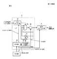
- FIG. 1 is a diagram for explaining a schematic configuration of a speed measuring device according to the present invention.
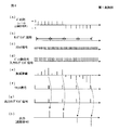
- FIG. 2 is a diagram for explaining a signal state of the speed measuring device according to the present invention.
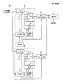
- FIG. 3 is a diagram for explaining a configuration example of the speed measuring device of the present invention.
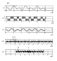
- FIG. 4 is a diagram for explaining a signal state of the configuration example of the speed measuring device according to the present invention.
- FIG. 5 is a diagram for explaining a second configuration example of the speed measuring device according to the present invention.
- FIG. 6 is a diagram for explaining a second configuration example of the speed measuring device according to the present invention.
- FIG. 7 is a diagram for explaining an example of speed measurement according to the present invention.
- FIG. 8 is a diagram for explaining an example of speed measurement according to the present invention.
- FIG. 9 is a diagram for explaining a schematic configuration of a conventional speed measuring device.
- FIG. 10 is a diagram for explaining a signal state of a conventional speed measuring device.
- FIGS. 1 and 2 are diagrams for explaining a schematic configuration and a signal state of a speed measuring device according to the present invention.
- FIGS. 3 and 4 are diagrams for explaining a first configuration example and a signal state of the speed measuring device according to the present invention.
- FIGS. 5 and 6 are diagrams for explaining a second configuration example of the speed measuring device of the present invention, and
- FIGS. 7 and 8 are diagrams for explaining a speed measuring example according to the present invention. .
- FIG. 1A shows a speed measuring apparatus 1 according to the present invention, in which an encoder 10 outputs an encoder pulse train of a two-phase signal in synchronization with a rotating body such as a rotating shaft.
- the phase relationship of the two-phase signal is changed to a phase advance state or a phase delay state depending on the moving direction such as the rotation direction, and information such as the rotation direction can be obtained from this phase state.
- the pulse train conversion unit 2 converts the pulse train signal ( ⁇ pulse train) into a three-valued up / down train of positive, negative, or 0 according to the phase relationship of the two-phase signal encoder pulse train.
- the pulse train signal can be formed, for example, by detecting the edge portion of the two-phase signal, and the sign of positive, negative, or 0 can be obtained based on the phase change state of the two-phase signal.
- FIG. 2 is a diagram for explaining pulse train conversion.
- FIG. 2A is an example of an encoder pulse train, and includes an A phase and a B phase that are out of phase with each other.
- the A phase and the B phase can have four phase relationships depending on the mutual phase relationship.
- reference numerals 1 to 4 are used.
- FIG. 2B shows the phase relationship when the rotating body rotates clockwise
- FIG. 2C shows the phase relationship when the rotating body rotates counterclockwise.
- the pulse train conversion unit 2 converts the A-phase and B-phase encoder pulses into a pulse train signal ( ⁇ pulse train) composed of a ternary up / down train of positive, negative, or 0 according to the moving direction (rotation direction). For example, when the A phase and the B phase change from the (0, 0) phase relationship to the (0, 1) phase relationship, a “+1” pulse train signal is output, and conversely, the A phase and the B phase When the phase relationship changes from (0, 1) to (0, 0), a pulse train signal of “ ⁇ 1” is output.
- FIG. 1B shows encoder pulses
- FIG. 1C shows a pulse train signal ( ⁇ pulse train) after pulse train conversion.
- the low-pass filter (LPF) 3 directly inputs the pulse train signal converted by the pulse train converter 2, and passes the low frequency band component included in the pulse train signal by calculating the filter coefficient to extract the speed signal component. To do.
- the output sampling unit 4 samples the output signal of the low pass filter 3 at a predetermined sampling period.
- a speed signal (FIG. 1 (d)) corresponding to the speed of the two-phase signal is output by the low frequency band pass process of the low pass filter 3 and the sampling process of the output sampling unit 4.
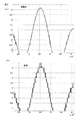
- FIGS. 1E and 1F are diagrams for explaining the difference in reduction of alias components depending on the order of low-pass filter processing and sampling processing.
- FIG. 1 (e) shows a conventional process in which low-pass filter processing is performed after sampling processing
- FIG. 1 (f) shows a case in which sampling processing is performed after low-pass filter processing in the present invention.
- the alias component (broken line in the figure) generated in the frequency (fs-fi) by the sampling process is a low pass filter (LPF) (FIG. It cannot be removed by the dot-dash line in the figure).
- LPF low pass filter
- the signal component is reduced by the low-pass filter (LPF) (the one-dot chain line in the figure).
- LPF low-pass filter
- the alias component (broken line in the figure) generated in the frequency (fs-fi) can be reduced.
- FIG. 3 shows a configuration example of the low-pass filter 3 provided in the speed measuring device.
- the configuration example shown in FIG. 3 shows an example of an FIR filter.
- the low-pass filter 3 performs a convolution operation (convolution operation) between the pulse train signal ( ⁇ pulse train) and the filter coefficient.
- the filter coefficient can be, for example, a coefficient constituting an FIR filter.
- the low-pass filter 3 samples and captures a pulse train signal, a read signal having a predetermined period, an input sampling signal having the same phase as the read signal, an output sampling signal having a sampling period, and an output sampling signal
- the counter unit 3e that outputs a reset signal synchronized with each other as a timing signal used for processing such as computation, and the readout signal of the counter unit 3e are input as a timing signal, and the filter coefficients are sequentially read out and output every predetermined period.
- the filter coefficient storage unit 3d, the multiplexer 3a that outputs one of the three input signals using the pulse train signal as a selection control input, and the filter coefficient read from the filter coefficient storage unit 3d at the output of the calculation result storage unit 3g.
- Adder 3b to add, calculation result notation It comprises a subtracter 3c for subtracting the filter coefficients read out from the filter coefficient storage section 3d from the output parts 3g, a calculation result storing part 3g for storing calculation results of the convolution calculation of the pulse train signal and the filter coefficients.
- the counter unit 3e can form a read signal and an input sampling signal with a predetermined period, and an output sampling signal and a reset signal with a sampling period.
- the multiplexer 3a selects and outputs the addition result of the adder 3b when the pulse train signal is positive, and selects the subtraction result of the subtractor 3c when the pulse train signal is negative.
- the value in the calculation result storage unit is selected and output.
- the output sampling unit 4 inputs the output sampling signal as a timing signal and samples the output of the multiplexer 3a. By sampling at the sampling period, calculation results with all the filter coefficients set for the low-pass filter processing are acquired, and a speed signal is output.
- the input sampling unit 3f samples and takes a binary pulse train signal using the input sampling signal as a timing signal, and sends it to the multiplexer 3a. Further, the filter coefficient storage unit 3d reads out the filter coefficients stored in advance based on the read signal and sends them to the adder 3b and the subtractor 3c.
- sampling of the pulse train signal and convolution calculation by the filter coefficient can be performed at the same clock signal timing.
- the counter unit 3e outputs a reset signal to the calculation result storage unit 3g at the sampling period.
- the calculation result storage unit 3g starts the convolution calculation from the beginning of the sampling cycle and ends the convolution calculation at the end of the sampling cycle.
- a convolution calculation is performed with the period interval of the sampling period as a unit, and a speed signal in the period of the sampling period can be obtained.
- FIG. 4A shows an example of a pulse train signal ( ⁇ pulse train), and switching from positive (+1) to negative ( ⁇ 1) indicates that the moving direction (rotating direction) has changed.
- FIG. 4B shows a sampling pulse that is sampled by the output sampling unit, and represents a measurement cycle interval.
- FIG. 4C shows a clock signal
- FIG. 4D shows a read signal and an input sampling signal.
- the read signal and the output sampling signal can be set based on the clock signal.
- the read signal and the output sampling signal can be formed by counting a predetermined number of clock signals.
- FIG. 4 (f) represents a reset signal
- FIG. 4 (g) represents an output sampling signal.
- the reset signal and output sampling signal are set based on the sampling period, and by outputting the reset signal simultaneously with the output sampling signal, the calculation result of the convolution calculation calculated during the sampling period can be output and reset .
- FIG. 4 (e) schematically shows an addition / subtraction value in the convolution calculation (convolution calculation) of the pulse train signal and the filter coefficient.
- a filter coefficient is added to or subtracted from the pulse train signal existing in the sampling interval in order based on the sign of the pulse train signal.
- the pulse train signal is a binary signal of ⁇ 1
- the adder 3b and the subtractor 3c sequentially add or subtract N + 1 filter coefficients a0 to aN to the output of the multiplexer 3a, and add / subtract values within the measurement period. Is output.
- FIG. 4 (h) outputs the calculation result of the convolution calculation (convolution calculation) at the cycle of the sampling cycle at the output sampling output timing. This output is a value corresponding to the speed signal.
- the second configuration example of the speed measuring device according to the present invention is configured such that a plurality of combinations of the low-pass filter 3 and the output sampling unit 4 shown in the first configuration example are configured in parallel.
- a pulse train signal obtained by conversion by the pulse train converter 2 is input to each combination of the sampling units 4.
- FIG. 5 shows an example in which three combinations of the low-pass filter 3 and the output sampling unit 4 are provided.
- the combination of the low-pass filter 3A and the output sampling unit 4A, the combination of the low-pass filter 3B and the output sampling unit 4B, and the low-pass filter Three combinations of 3C and the output sampling unit 4C are shown.
- Each of the low-pass filters 3A, 3B, and 3C shifts the timing of each sampling by shifting the phase of the input sampling signal in the input sampling unit that samples the pulse train signal, and also reads the filter coefficient by shifting the phase of the readout signal. And the output signals obtained by shifting the phases are combined to substantially increase the number of samplings.
- the phase of each input sampling signal and each readout signal can be shifted by 1/3 period.
- a delay circuit can be used as the means for shifting the phase of the input sampling signal and each readout signal.
- each output sampling unit 4A, 4B, 4C is input to the calculation unit 7 and outputs a speed signal.
- the calculation unit 7 sequentially outputs the outputs of the output sampling units 4A, 4B, and 4C as they are, or performs time series processing in units of measurement periods, and calculates an addition value or an average value for each output in each measurement period. .
- FIG. 6 shows a configuration example in which two combinations of a combination of the low-pass filter 3A and the output sampling unit 4A and a combination of the low-pass filter 3B and the output sampling unit 4B are arranged in parallel.
- the configuration of the low-pass filter 3A and the output sampling unit 4A, and the configuration of the low-pass filter 3B and the output sampling unit 4B shown in FIG. 6 can be substantially the same as the configuration shown in FIG. 3, and the configuration for inputting to the counter unit 3e is different. is doing.
- the counter unit 3e of the low-pass filter 3A receives a clock signal from the clock unit 5, and based on the period and phase of this clock signal, a read signal and input sampling signal of a predetermined period, a set signal and output sampling of a measurement period Form a signal.
- the low-pass filter 3B includes a delay circuit 6 in the counter unit 3e.
- the delay circuit 6 shifts the phase of the signal of the counter unit 3e of the low-pass filter 3A, and forms a read signal and an input sampling signal, and a reset signal and an output sampling signal of the measurement period based on the delayed signal whose phase is shifted.
- the delay circuit 6 forms a phase difference by sending the phases of the read signal and the input sampling signal by a half cycle.
- FIG. 7A shows the pulse train of the encoder output as a count value.
- FIG. 7B shows a pulse train signal ( ⁇ pulse train) output from the pulse train converter.
- the positive pulse train signal corresponds to a period during which the encoder output count value increases, and the negative pulse train signal corresponds to a period during which the encoder output count value decreases.
- FIG. 7C shows the speed measured by the present invention and the conventional measurement speed.
- FIG. 8 shows an enlarged view of FIG.
- FIG. 8A shows an example of the speed signal obtained in the embodiment according to the first configuration example of the present invention
- FIG. 8B shows an example of the speed signal obtained by the difference of the conventional sampling.
- the broken line in FIG. 11 has shown the true speed.
- FIG. 7D shows an error between the speed of the input signal from the encoder and the output signal of the measurement speed.
- B represents an error in the conventional speed measurement
- A represents an error in the speed measurement of the present invention. According to the present invention, it is confirmed that the input error is reduced.
- FIG. 7E shows the relationship between the speed of the input signal from the encoder and the error between the output signal of the measured speed and the speed.
- B represents the relationship between speed and error in the conventional speed measurement
- A represents the relationship between speed and error in the speed measurement of the present invention.
- the horizontal axis of FIG.7 (e) represents speed and the vertical axis
- shaft represents the error.
- FIG. 7 (e) shows that in the conventional speed measurement, the magnitude of the input / output error exists regardless of the speed, whereas according to the speed measurement of the present invention, the input / output error is almost zero. It is confirmed that the input error is reduced to an almost negligible level during the period when the direction changes and has speed.
- the speed measuring device of the present invention can be applied not only to the measurement of the rotational speed but also to the speed measurement of a moving body that moves on a straight line or a curve.
Landscapes
- Physics & Mathematics (AREA)
- General Physics & Mathematics (AREA)
- Measuring Frequencies, Analyzing Spectra (AREA)
Abstract
Description
ローパスフィルタは、パルス列信号に含まれる高周波数域成分を低減し、低周波数域成分を抽出する演算を、パルス列信号とフィルタ係数とのたたみ込み演算(コンボリューション演算)によって行う。フィルタ係数は例えばFIRフィルタを構成する係数とすることができる。
本発明の速度測定方法は、2相信号をこの2相信号の位相関係に応じて正又は負又は0の3値のパルス列信号に変換するパルス列信号変換工程と、パルス列信号とフィルタ係数との演算によってパルス列信号の低周波数域成分を取得するローパス工程と、ローパス工程の出力信号を所定の測定周期毎にサンプリングする出力サンプリング工程とを有し、出力サンプリング工程のサンプリング値を2相信号の速度に対応する速度信号として出力する。
はじめに、本願発明の速度測定装置の構成の概略について図1,2を用いて説明する。図1(a)は本願発明の速度測定装置1において、エンコーダ10は回転軸等の回転体と同期して2相信号のエンコーダパルス列を出力する。2相のエンコーダパルス列は、回転方向等の移動方向によって2相信号の位相関係は位相進みの状態又は位相遅れの状態となり、この位相状態から回転方向等の情報を得ることができる。
本願発明の速度測定装置の第1の構成例について図3,4を用いて説明する。図3は速度測定装置が備えるローパスフィルタ3の構成例を示している。図3に示す構成例はFIRフィルタの例を示している。
本願発明の速度測定装置の第2の構成例について図5、図6を用いて説明する。第2の構成例は、ローパスフィルタと出力サンプリング部の組み合わせを複数組並列に構成し、各組で得られた互いに位相を異にする出力を組み合わせることによってサンプリング回数を実質的に高め、短いサンプリング間隔におるサンプリング出力を得るものである。
本願発明による速度測定例を図7,8を用いて説明する。
2 パルス列変換部
3 ローパスフィルタ
3A,3B,3C ローパスフィルタ
3a マルチプレクサ
3b 加算器
3c 減算器
3d フィルタ係数記憶部
3e カウンタ部
3f 入力サンプリング部
3g 演算結果記憶部
4 出力サンプリング部
4A,4B,4C 出力サンプリング部
5 クロック部
6 遅延回路
7 演算部
10 エンコーダ
100 エンコーダ
101 速度測定装置
102 カウンタ部
103 サンプリング部
104 差分検出部
Claims (7)
- 2相信号を当該2相信号の位相関係に応じて正又は負又は0の3値のパルス列信号に変換するパルス列変換部と、
前記3値のパルス列信号とフィルタ係数との演算によって、前記パルス列信号の低周波数域成分を出力するローパスフィルタと、
前記ローパスフィルタの出力信号を所定のサンプリング周期毎にサンプリングして前記2相信号の速度に対応する速度信号を出力する出力サンプリング部と、
を備えることを特徴とする速度測定装置。
- 前記ローパスフィルタの演算は、前記3値のパルス列信号とフィルタ係数とのたたみ込み演算(コンボリューション演算)であり、
前記ローパスフィルタは、
所定周期の読み出し信号と、前記読み出し信号と同期すると共に同位相の入力サンプリング信号と、サンプリング周期の出力サンプリング信号とをタイミング信号として出力するカウンタ部と、
前記3値のパルス列信号を入力サンプリング信号に基づいてサンプリングする入力サンプリング部と、
前記フィルタ係数を記憶し、前記読み出し信号毎にフィルタ係数を読み出すフィルタ係数記憶部と、
前記3値のパルス列信号を選択制御入力として、3つの入力信号の何れか一方を出力するマルチプレクサと、
前記フィルタ係数記憶部から読み出されたフィルタ係数を加算する加算器と、
前記フィルタ係数記憶部から読み出されたフィルタ係数を減算する減算器と、
パルス列信号とフィルタ係数とのたたみ込み演算の演算結果を記憶する演算結果記憶部とを備え、
前記マルチプレクサは、入力される前記加算器の出力信号と前記減算器の出力信号と前記演算結果記憶部の出力信号の内、前記3値のパルス列信号において、パルス列信号が正であるときは前記加算器の出力信号を選択して出力し、パルス列信号が負であるときは前記減算器の出力信号を選択し、パルス列信号が0であるときは前記演算結果部の出力信号を出力し、
前記演算結果記憶部は、サンプリング周期毎に前記マルチプレクサの出力信号をサンプリングして速度信号として出力することを特徴とする、請求項1に記載の速度測定装置。
- (FIR有限インパルス応答)
前記ローパスフィルタはFIRフィルタを構成し、
前記カウンタ部は前記タイミング信号としてサンプリング周期のリセット信号を含み、
前記加算器は、前記演算結果記憶部の出力信号に前記フィルタ係数記憶部から読み出されたフィルタ係数を加算し、
前記減算器は、前記演算結果記憶部の出力信号から前記フィルタ係数記憶部から読み出されたフィルタ係数を減算し、
前記演算結果記憶部は、前記リセット信号によりサンプリング周期毎に演算結果をリセットすることを特徴とする、請求項2に記載の速度測定装置。
- (複数のローパスフィルタの構成例)
前記ローパスフィルタと前記出力サンプリング部との組み合わせを少なくとも2組備え、
各組のローパスフィルタは、前記パルス列変換部から共通の3値のパルス列信号を入力し、
各組の入力サンプリング部は、
ローパスフィルタ間でそれぞれ同期すると共に異なる位相の入力サンプリング信号によって前記3値のパルス列信号をサンプリングして入力し、
各組のフィルタ係数記憶部は、各ローパスフィルタ内では入力サンプリング信号と同期すると共に同位相とし、各ローパスフィルタ間ではそれぞれ同期すると共に異なる位相の読み出し信号に基づいてフィルタ係数を読み出し、
各組の加算器および減算器は、各組のフィルタ係数記憶部から読み出したフィルタ係数をそれぞれ加算あるいは減算し、
各出力サンプリング部の出力信号を時系列で順次、または組み合わせて演算して出力することを特徴とする、請求項2又は3に記載の速度測定装置。
- (請求項1の装置に対応した方法の請求項)
2相信号を当該2相信号の位相関係に応じて正又は負又は0の3値のパルス列信号に変換するパルス列信号変換工程と、
前記3値のパルス列信号とフィルタ係数との演算によって前記パルス列信号の低周波数域成分を取得するローパス工程と、
前記ローパス工程の出力信号を所定のサンプリング定周期毎にサンプリングする出力サンプリング工程とを有し、
前記出力サンプリング工程のサンプリング値を前記2相信号の速度に対応する速度信号として出力することを特徴とする速度測定方法。
- (請求項2の装置に対応した方法の請求項)
前記ローパス工程は、前記3値のパルス列信号を所定周期でサンプリングし、前記サンプリングした3値のパルス列信号に基づいて、前記パルス列信号とフィルタ係数とのたたみ込み演算(コンボリューション演算)を行い、
前記たたみ込み演算は、前記3値のパルス列信号において、パルス列信号の正であるときには前記フィルタ係数を加算し、前記パルス列信号が負であるときには前記フィルタ係数を減算する加減算であり、フィルタ係数の読み出しは前記パルス列信号のサンプリングと同期すると共に同位相で行い、
前記出力サンプリング工程は、前記たたみ込み演算の演算結果を前記サンプリング周期毎にサンプリングして速度信号として出力することを特徴とする、請求項5に記載の速度測定方法。
- (請求項4の装置に対応した方法の請求項)
共通のパルス列信号を入力する前記ローパス工程と前記出力サンプリング工程の処理工程の組み合わせを複数組有し、
同じローパス工程内において、前記パルス列信号のサンプリングとたたみ込み演算のフィルタ係数の読み出しとは同期すると共に同位相とし、
異なるローパス工程間において、前記パルス列信号のサンプリングとたたみ込み演算のフィルタ係数の読み出しは、同期すると共に異なる位相であることを特徴とする、請求項5又は6に記載の速度測定方法。
Priority Applications (4)
| Application Number | Priority Date | Filing Date | Title |
|---|---|---|---|
| US14/648,826 US20150331006A1 (en) | 2012-12-26 | 2013-12-25 | Velocity Measurement Device and Velocity Measurement Method |
| CN201380066169.0A CN105008934A (zh) | 2012-12-26 | 2013-12-25 | 速度测定装置以及速度测定方法 |
| EP13870074.5A EP2940479B1 (en) | 2012-12-26 | 2013-12-25 | Velocity measurement device and velocity measurement method |
| JP2014555453A JP6325458B2 (ja) | 2012-12-26 | 2013-12-25 | 速度測定装置および速度測定方法 |
Applications Claiming Priority (2)
| Application Number | Priority Date | Filing Date | Title |
|---|---|---|---|
| JP2012-283278 | 2012-12-26 | ||
| JP2012283278 | 2012-12-26 |
Publications (1)
| Publication Number | Publication Date |
|---|---|
| WO2014106937A1 true WO2014106937A1 (ja) | 2014-07-10 |
Family
ID=51021015
Family Applications (2)
| Application Number | Title | Priority Date | Filing Date |
|---|---|---|---|
| PCT/JP2013/084248 Ceased WO2014103931A1 (ja) | 2012-12-26 | 2013-12-20 | 速度測定装置および速度測定方法 |
| PCT/JP2013/084579 Ceased WO2014106937A1 (ja) | 2012-12-26 | 2013-12-25 | 速度測定装置および速度測定方法 |
Family Applications Before (1)
| Application Number | Title | Priority Date | Filing Date |
|---|---|---|---|
| PCT/JP2013/084248 Ceased WO2014103931A1 (ja) | 2012-12-26 | 2013-12-20 | 速度測定装置および速度測定方法 |
Country Status (5)
| Country | Link |
|---|---|
| US (1) | US20150331006A1 (ja) |
| EP (1) | EP2940479B1 (ja) |
| JP (1) | JP6325458B2 (ja) |
| CN (1) | CN105008934A (ja) |
| WO (2) | WO2014103931A1 (ja) |
Families Citing this family (8)
| Publication number | Priority date | Publication date | Assignee | Title |
|---|---|---|---|---|
| CN106771326B (zh) * | 2016-11-18 | 2019-04-23 | 威科达(东莞)智能控制有限公司 | 一种基于增量式光电编码器测量速度的方法 |
| US9877042B1 (en) * | 2017-05-26 | 2018-01-23 | Mitutoyo Corporation | Position encoder sample timing system |
| JP7002892B2 (ja) * | 2017-09-08 | 2022-01-20 | 株式会社ミツトヨ | 形状測定装置の制御方法 |
| JP6932585B2 (ja) * | 2017-09-08 | 2021-09-08 | 株式会社ミツトヨ | 形状測定装置の制御方法 |
| JP7275827B2 (ja) * | 2019-05-10 | 2023-05-18 | オムロン株式会社 | カウンタユニット、データ処理装置、計測システム、カウンタユニット制御方法、およびデータ処理方法 |
| CN110567495B (zh) * | 2019-08-26 | 2021-05-25 | 中国美术学院 | 三态值编码方法及其编码器 |
| JP7530187B2 (ja) * | 2020-03-11 | 2024-08-07 | キヤノン株式会社 | データ処理装置、データ処理方法 |
| CN111860778B (zh) * | 2020-07-08 | 2025-05-13 | 北京灵汐科技有限公司 | 一种全加卷积方法和装置 |
Citations (4)
| Publication number | Priority date | Publication date | Assignee | Title |
|---|---|---|---|---|
| JPS58113766A (ja) * | 1981-12-26 | 1983-07-06 | Nippon Seiki Co Ltd | パルス計数装置 |
| JPH08201111A (ja) * | 1995-01-30 | 1996-08-09 | Sony Magnescale Inc | 内挿装置 |
| JP2002062163A (ja) * | 2000-08-16 | 2002-02-28 | Tdk Corp | 磁気回転センサ |
| JP2009250807A (ja) | 2008-04-07 | 2009-10-29 | Seiko Epson Corp | 周波数測定装置及び測定方法 |
Family Cites Families (9)
| Publication number | Priority date | Publication date | Assignee | Title |
|---|---|---|---|---|
| US4103234A (en) * | 1967-11-24 | 1978-07-25 | General Dynamics Corp. | System for transmission storage and/or multiplexing of information |
| JPH07104689B2 (ja) * | 1986-11-07 | 1995-11-13 | フアナツク株式会社 | パルスエンコ−ダ |
| ES2106933T3 (es) * | 1992-10-21 | 1997-11-16 | Bosch Gmbh Robert | Dispositivo para la deteccion del movimiento de una parte movil. |
| DE69613867T2 (de) * | 1995-01-30 | 2001-10-31 | Sony Prec Technology Inc | Interpolationsgerät |
| KR100460592B1 (ko) * | 2002-08-22 | 2004-12-09 | 삼성전자주식회사 | 모터 속도 제어장치 |
| US7183935B2 (en) * | 2004-10-14 | 2007-02-27 | Rockwell Automation Technologies, Inc. | Method and apparatus for determining motor velocity using edge mode hysteresis with a finite impulse response average filter |
| JP4317855B2 (ja) * | 2006-02-15 | 2009-08-19 | 三菱電機株式会社 | 磁気検出装置 |
| JP4646044B2 (ja) * | 2008-06-09 | 2011-03-09 | 三菱電機株式会社 | 磁気検出装置 |
| JP4859903B2 (ja) * | 2008-10-23 | 2012-01-25 | 三菱電機株式会社 | 移動方向検出装置 |
-
2013
- 2013-12-20 WO PCT/JP2013/084248 patent/WO2014103931A1/ja not_active Ceased
- 2013-12-25 US US14/648,826 patent/US20150331006A1/en not_active Abandoned
- 2013-12-25 WO PCT/JP2013/084579 patent/WO2014106937A1/ja not_active Ceased
- 2013-12-25 JP JP2014555453A patent/JP6325458B2/ja active Active
- 2013-12-25 EP EP13870074.5A patent/EP2940479B1/en not_active Not-in-force
- 2013-12-25 CN CN201380066169.0A patent/CN105008934A/zh active Pending
Patent Citations (4)
| Publication number | Priority date | Publication date | Assignee | Title |
|---|---|---|---|---|
| JPS58113766A (ja) * | 1981-12-26 | 1983-07-06 | Nippon Seiki Co Ltd | パルス計数装置 |
| JPH08201111A (ja) * | 1995-01-30 | 1996-08-09 | Sony Magnescale Inc | 内挿装置 |
| JP2002062163A (ja) * | 2000-08-16 | 2002-02-28 | Tdk Corp | 磁気回転センサ |
| JP2009250807A (ja) | 2008-04-07 | 2009-10-29 | Seiko Epson Corp | 周波数測定装置及び測定方法 |
Also Published As
| Publication number | Publication date |
|---|---|
| JPWO2014106937A1 (ja) | 2017-01-19 |
| EP2940479B1 (en) | 2018-10-03 |
| CN105008934A (zh) | 2015-10-28 |
| EP2940479A4 (en) | 2016-09-07 |
| JP6325458B2 (ja) | 2018-05-16 |
| US20150331006A1 (en) | 2015-11-19 |
| EP2940479A1 (en) | 2015-11-04 |
| WO2014103931A1 (ja) | 2014-07-03 |
Similar Documents
| Publication | Publication Date | Title |
|---|---|---|
| JP6325458B2 (ja) | 速度測定装置および速度測定方法 | |
| TWI450499B (zh) | 在樣本速率轉換系統內計算內插因子的方法與設備 | |
| KR102309359B1 (ko) | 레인지 및 감도가 상승한 시간-디지털 컨버터 | |
| JP3015747B2 (ja) | エンコーダの内挿回路 | |
| JP5142342B2 (ja) | Ad変換回路 | |
| JP4306515B2 (ja) | 同期検波方法及び装置 | |
| CN106841086A (zh) | 一种提高大气探测傅里叶光谱仪信噪比的方法 | |
| US7526395B2 (en) | Logic analyzer using a digital filter | |
| CN106645780B (zh) | 一种基于dsp的转速检测方法及系统 | |
| JPH10126218A (ja) | サンプリング周波数変換装置 | |
| JPWO2011090110A1 (ja) | サンプリングレート変換装置およびサンプリングレート変換方法 | |
| JP5529666B2 (ja) | 位置検出装置 | |
| JP2013205093A (ja) | ディジタル位相検波器 | |
| JP4355395B2 (ja) | 位置検出データ生成方法及び装置 | |
| JP4953714B2 (ja) | エンコーダ出力の内挿方法及び内挿回路 | |
| JP4682968B2 (ja) | エンコーダの位置情報補間回路 | |
| JP2005140737A (ja) | 磁気式エンコーダ装置 | |
| JP2019020294A (ja) | 回転角センサ−デジタルコンバータおよび回転角センサ−デジタル変換方法 | |
| JP4240269B2 (ja) | 波形測定器 | |
| JPH01269297A (ja) | 標本化周波数変換装置 | |
| JP2003130686A (ja) | 位置検出装置 | |
| CN101515156A (zh) | 时间精密测量方法 | |
| TW200427277A (en) | Detector, method, program and recording medium | |
| JP3015751B2 (ja) | エンコーダの内挿回路 | |
| JPH1062203A (ja) | 位置検出装置 |
Legal Events
| Date | Code | Title | Description |
|---|---|---|---|
| 121 | Ep: the epo has been informed by wipo that ep was designated in this application |
Ref document number: 13870074 Country of ref document: EP Kind code of ref document: A1 |
|
| WWE | Wipo information: entry into national phase |
Ref document number: 14648826 Country of ref document: US |
|
| WWE | Wipo information: entry into national phase |
Ref document number: 2013870074 Country of ref document: EP |
|
| ENP | Entry into the national phase |
Ref document number: 2014555453 Country of ref document: JP Kind code of ref document: A |
|
| NENP | Non-entry into the national phase |
Ref country code: DE |