WO2014115771A1 - 噴霧器用メッシュおよびその製造方法 - Google Patents
噴霧器用メッシュおよびその製造方法 Download PDFInfo
- Publication number
- WO2014115771A1 WO2014115771A1 PCT/JP2014/051270 JP2014051270W WO2014115771A1 WO 2014115771 A1 WO2014115771 A1 WO 2014115771A1 JP 2014051270 W JP2014051270 W JP 2014051270W WO 2014115771 A1 WO2014115771 A1 WO 2014115771A1
- Authority
- WO
- WIPO (PCT)
- Prior art keywords
- mesh
- sprayer
- resist
- resist pattern
- stage
- Prior art date
- Legal status (The legal status is an assumption and is not a legal conclusion. Google has not performed a legal analysis and makes no representation as to the accuracy of the status listed.)
- Ceased
Links
Images





Classifications
-
- A—HUMAN NECESSITIES
- A61—MEDICAL OR VETERINARY SCIENCE; HYGIENE
- A61M—DEVICES FOR INTRODUCING MEDIA INTO, OR ONTO, THE BODY; DEVICES FOR TRANSDUCING BODY MEDIA OR FOR TAKING MEDIA FROM THE BODY; DEVICES FOR PRODUCING OR ENDING SLEEP OR STUPOR
- A61M11/00—Sprayers or atomisers specially adapted for therapeutic purposes
- A61M11/001—Particle size control
- A61M11/003—Particle size control by passing the aerosol trough sieves or filters
-
- A—HUMAN NECESSITIES
- A61—MEDICAL OR VETERINARY SCIENCE; HYGIENE
- A61M—DEVICES FOR INTRODUCING MEDIA INTO, OR ONTO, THE BODY; DEVICES FOR TRANSDUCING BODY MEDIA OR FOR TAKING MEDIA FROM THE BODY; DEVICES FOR PRODUCING OR ENDING SLEEP OR STUPOR
- A61M15/00—Inhalators
- A61M15/0085—Inhalators using ultrasonics
-
- B—PERFORMING OPERATIONS; TRANSPORTING
- B05—SPRAYING OR ATOMISING IN GENERAL; APPLYING FLUENT MATERIALS TO SURFACES, IN GENERAL
- B05B—SPRAYING APPARATUS; ATOMISING APPARATUS; NOZZLES
- B05B1/00—Nozzles, spray heads or other outlets, with or without auxiliary devices such as valves, heating means
- B05B1/26—Nozzles, spray heads or other outlets, with or without auxiliary devices such as valves, heating means with means for mechanically breaking-up or deflecting the jet after discharge, e.g. with fixed deflectors; Breaking-up the discharged liquid or other fluent material by impinging jets
-
- B—PERFORMING OPERATIONS; TRANSPORTING
- B05—SPRAYING OR ATOMISING IN GENERAL; APPLYING FLUENT MATERIALS TO SURFACES, IN GENERAL
- B05B—SPRAYING APPARATUS; ATOMISING APPARATUS; NOZZLES
- B05B17/00—Apparatus for spraying or atomising liquids or other fluent materials, not covered by the preceding groups
- B05B17/04—Apparatus for spraying or atomising liquids or other fluent materials, not covered by the preceding groups operating with special methods
- B05B17/06—Apparatus for spraying or atomising liquids or other fluent materials, not covered by the preceding groups operating with special methods using ultrasonic or other kinds of vibrations
- B05B17/0607—Apparatus for spraying or atomising liquids or other fluent materials, not covered by the preceding groups operating with special methods using ultrasonic or other kinds of vibrations generated by electrical means, e.g. piezoelectric transducers
- B05B17/0638—Apparatus for spraying or atomising liquids or other fluent materials, not covered by the preceding groups operating with special methods using ultrasonic or other kinds of vibrations generated by electrical means, e.g. piezoelectric transducers spray being produced by discharging the liquid or other fluent material through a plate comprising a plurality of orifices
- B05B17/0646—Vibrating plates, i.e. plates being directly subjected to the vibrations, e.g. having a piezoelectric transducer attached thereto
-
- C—CHEMISTRY; METALLURGY
- C25—ELECTROLYTIC OR ELECTROPHORETIC PROCESSES; APPARATUS THEREFOR
- C25D—PROCESSES FOR THE ELECTROLYTIC OR ELECTROPHORETIC PRODUCTION OF COATINGS; ELECTROFORMING; APPARATUS THEREFOR
- C25D1/00—Electroforming
- C25D1/08—Perforated or foraminous objects, e.g. sieves
-
- C—CHEMISTRY; METALLURGY
- C25—ELECTROLYTIC OR ELECTROPHORETIC PROCESSES; APPARATUS THEREFOR
- C25D—PROCESSES FOR THE ELECTROLYTIC OR ELECTROPHORETIC PRODUCTION OF COATINGS; ELECTROFORMING; APPARATUS THEREFOR
- C25D3/00—Electroplating: Baths therefor
- C25D3/02—Electroplating: Baths therefor from solutions
- C25D3/50—Electroplating: Baths therefor from solutions of platinum group metals
-
- C—CHEMISTRY; METALLURGY
- C25—ELECTROLYTIC OR ELECTROPHORETIC PROCESSES; APPARATUS THEREFOR
- C25D—PROCESSES FOR THE ELECTROLYTIC OR ELECTROPHORETIC PRODUCTION OF COATINGS; ELECTROFORMING; APPARATUS THEREFOR
- C25D5/00—Electroplating characterised by the process; Pretreatment or after-treatment of workpieces
- C25D5/02—Electroplating of selected surface areas
-
- C—CHEMISTRY; METALLURGY
- C25—ELECTROLYTIC OR ELECTROPHORETIC PROCESSES; APPARATUS THEREFOR
- C25D—PROCESSES FOR THE ELECTROLYTIC OR ELECTROPHORETIC PRODUCTION OF COATINGS; ELECTROFORMING; APPARATUS THEREFOR
- C25D5/00—Electroplating characterised by the process; Pretreatment or after-treatment of workpieces
- C25D5/02—Electroplating of selected surface areas
- C25D5/022—Electroplating of selected surface areas using masking means
-
- C—CHEMISTRY; METALLURGY
- C25—ELECTROLYTIC OR ELECTROPHORETIC PROCESSES; APPARATUS THEREFOR
- C25D—PROCESSES FOR THE ELECTROLYTIC OR ELECTROPHORETIC PRODUCTION OF COATINGS; ELECTROFORMING; APPARATUS THEREFOR
- C25D5/00—Electroplating characterised by the process; Pretreatment or after-treatment of workpieces
- C25D5/48—After-treatment of electroplated surfaces
-
- C—CHEMISTRY; METALLURGY
- C25—ELECTROLYTIC OR ELECTROPHORETIC PROCESSES; APPARATUS THEREFOR
- C25D—PROCESSES FOR THE ELECTROLYTIC OR ELECTROPHORETIC PRODUCTION OF COATINGS; ELECTROFORMING; APPARATUS THEREFOR
- C25D7/00—Electroplating characterised by the article coated
- C25D7/04—Tubes; Rings; Hollow bodies
-
- A—HUMAN NECESSITIES
- A61—MEDICAL OR VETERINARY SCIENCE; HYGIENE
- A61M—DEVICES FOR INTRODUCING MEDIA INTO, OR ONTO, THE BODY; DEVICES FOR TRANSDUCING BODY MEDIA OR FOR TAKING MEDIA FROM THE BODY; DEVICES FOR PRODUCING OR ENDING SLEEP OR STUPOR
- A61M2205/00—General characteristics of the apparatus
- A61M2205/02—General characteristics of the apparatus characterised by a particular materials
- A61M2205/0244—Micromachined materials, e.g. made from silicon wafers, microelectromechanical systems [MEMS] or comprising nanotechnology
-
- A—HUMAN NECESSITIES
- A61—MEDICAL OR VETERINARY SCIENCE; HYGIENE
- A61M—DEVICES FOR INTRODUCING MEDIA INTO, OR ONTO, THE BODY; DEVICES FOR TRANSDUCING BODY MEDIA OR FOR TAKING MEDIA FROM THE BODY; DEVICES FOR PRODUCING OR ENDING SLEEP OR STUPOR
- A61M2207/00—Methods of manufacture, assembly or production
Definitions
- the present invention relates to a mesh for a sprayer used for the treatment of respiratory diseases and a method for producing the same. More specifically, the present invention relates to a nebulizer mesh that is used for atomizing a liquid and controlling the particle diameter in a nebulizer for atomizing and ejecting a liquid and having a plurality of through holes, and a method for manufacturing the mesh.
- Nebulizers used for the treatment of respiratory diseases are required to have the ability to efficiently reach the target affected area in order to improve the therapeutic effect.
- the sprayed drug solution particles can reach the bronchus, the bronchioles in the back, and the alveoli as the particle size decreases.
- the therapeutic effect can be enhanced by securing a sufficient spray amount. Therefore, in order to improve the performance of the sprayer, it is necessary to reduce the particle size of the chemical liquid sprayed from the sprayer and increase the spray amount.
- FIG. 5 is a cross-sectional view of the process of obtaining a sprayer mesh by performing thick electroplating on a Cu substrate as a matrix.
- a mother die 51 is prepared.
- An example of the mother die 51 is a Cu substrate.
- a resist pattern 52 is formed in a predetermined shape on the mother die 51.
- the shape is, for example, a circle.
- the electroformed film 53 is deposited by performing, for example, thick electroplating including platinum as a main component.
- the electroformed film 53 is initially deposited on a portion of the mother die 51 that is not covered with the resist pattern 52 and grows only in a direction perpendicular to the surface of the mother die 51 (longitudinal direction).
- the electroformed film 53 grows in a direction parallel to the surface of the mother die 51 (lateral direction).
- the conventional electroforming method has a problem that it is difficult to appropriately control the size of the through hole, the spray amount varies from product to product, and the production yield is poor.
- an object of the present invention is to provide a sprayer mesh that has a plurality of through-holes and from which the liquid is atomized and ejected, and appropriately controls the size of the through-holes to reduce the diameter of the droplet particles to be sprayed. It is an object of the present invention to provide a mesh for a nebulizer and a method for producing the same, which can sufficiently reduce the amount of spray and increase the production yield by suppressing variation in the spray amount for each product.
- the present inventors have adopted a special process using two resist patterns, and can form the through-hole formed in the mesh for the sprayer into a specific shape to solve the above problem.
- the headline and the present invention were completed.
- the present invention is as follows. 1. A nebulizer mesh that is used to atomize a liquid in a nebulizer for atomizing and ejecting liquid, and has a plurality of through holes, The sprayer mesh, wherein the through-hole is formed such that one surface of the sprayer mesh forms a cylindrical space portion, and the other surface forms an opening in a mortar shape. 2.
- a method for producing a mesh for a sprayer that is used to atomize a liquid in a sprayer for atomizing and ejecting the liquid and has a plurality of through holes, A first step of forming a first-stage resist pattern in a predetermined shape on the matrix, and then a second step of forming a second-stage resist pattern in a columnar shape on the first-stage resist pattern; After the second step, a third step of performing metal plating to form the through hole of the atomizer mesh, and a fourth step of removing the matrix and the first and second step resist patterns, Including The through-hole formed by the third step is formed by forming one side of the atomizer mesh to form a cylindrical space portion and the other side to form a mortar-shaped opening.
- the shape of the space portion is determined by the shape of the second-stage resist pattern formed in the second step. 7). 7. The method for producing a sprayer mesh according to item 6 above, wherein the sprayer mesh contains platinum as a main component. 8). 8. The method for producing a mesh for a sprayer according to 6 or 7 above, wherein the height of the cylindrical space portion is 0.1 ⁇ m to 20 ⁇ m. 9. 9. The method for producing a mesh for a sprayer according to any one of items 6 to 8, wherein a diameter of the cylindrical space portion is 0.3 ⁇ m to 10 ⁇ m. 10. Any of 6 to 9 above, wherein the resist that forms the first-stage resist pattern is a polyimide-based resist, and the resist that forms the second-stage resist pattern is an epoxy-based resist. A method for producing a mesh for a sprayer according to claim 1.
- the sprayer mesh and the manufacturing method thereof according to the present invention a special process using two resist patterns is adopted, and the through hole formed in the sprayer mesh is formed into a specific shape. Is appropriately controlled, and the diameter of the droplet particles to be sprayed can be sufficiently reduced, and the production yield can be increased by suppressing the variation in the spray amount for each product.
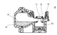
- FIG. 1 is a schematic cross-sectional view showing a configuration when the nebulizer mesh of the present invention is used in an ultrasonic vibration type nebulizer (nebulizer).
- FIG. 2A is a perspective view showing the appearance of the mesh, and FIG. 2B is a partially enlarged view thereof.
- FIG. 3 is a cross-sectional view for explaining a mesh through-hole.
- 4A to 4E are cross-sectional views of the mesh for explaining the manufacturing method of the present invention.
- 5 (a) to 5 (e) are cross-sectional views of a process for producing a sprayer mesh by a conventional electroforming method.
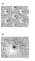
- 6A and 6B are electron micrographs taken from the upper surface of the resist pattern formed in the second step in Example 1.
- FIG. 1 is a schematic cross-sectional view showing a configuration when the nebulizer mesh of the present invention is used in an ultrasonic vibration type nebulizer (nebulizer).
- FIG. 2A is a perspective view
- FIGS. 7A and 7B are electron micrographs from the top surface of the electroformed film 43 after plating in the third step in Example 1.
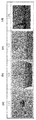
- FIG. FIGS. 8A to 8D are cross-sectional photographs of a part of the through holes of the atomizer mesh obtained in Example 1.
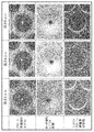
- FIG. 9 shows the resist state after resist pattern formation and the electroformed film side after plating when the height of the second-stage resist pattern 422 is 2 ⁇ m, 4 ⁇ m, or 6 ⁇ m in Example 1. It is an electron micrograph for demonstrating the state after peeling the resist pattern of the back side.
- FIGS. 10A to 10D are cross-sectional photographs of a part of the through holes of the nebulizer mesh obtained in Comparative Example 1.
- FIG. FIG. 11 is a graph of the results of Table 2 for the maximum frequency distribution change for each hole diameter.
- FIG. 12 is a diagram in which the results of Table 2 are graphed with respect to variation in variation for each hole diameter.
- FIG. 1 shows a configuration of a sprayer for carrying out the present invention, but the configuration is not limited to these configurations.
- FIG. 1 is a schematic cross-sectional view showing a configuration when a nebulizer mesh (hereinafter also referred to as a mesh) of the present invention is used in an ultrasonic vibration type nebulizer (nebulizer) 10.
- a mesh 11 having a plurality of fine through holes as shown in FIG. 2 is fixed inside the casing 12, and the upper surface of the vibrator 13 is pressed against the lower surface of the mesh 11, The end of the vibrator 13 has a structure that can come into contact with the liquid 15 held in the tank 14. Further, the mesh 11 is held by a mesh support 16.
- the mesh 11 used in the inhaler 10 is composed of a large number of through-holes 17 that are sufficiently fine to atomize (atomize) the liquid 15 as shown in FIG.
- FIG. 2 is a perspective view (a) and a partially enlarged view (b) showing the appearance of the mesh 11.
- the mesh 11 has a plate-like outer shape.
- the mesh 11 has a plurality of through holes 17.
- the mesh 11 pressed against the vibrator 13 by the mesh support 16 with an appropriate force resonates due to the minute vibration of the vibrator 13.
- the mesh 11 resonates, a negative pressure is generated between the mesh 11 and the vibrator 13, so that the liquid 15 in the tank 14 is sucked up to the upper surface of the vibrator 13.
- the liquid 15 sucked up between the mesh 11 and the vibrator 13 passes through the fine through-hole 17 by the vibration of the mesh 11, and the atomized liquid 15 is jetted into the outside air.
- FIG. 3 is a cross-sectional view of the mesh for explaining the through-hole 17 of the mesh for a sprayer of the present invention.
- the through-hole 17 is formed by forming an opening 172 in which one surface of the mesh 11 forms a cylindrical space portion 174 and the other surface expands in a mortar shape. That is, the other surface of the through hole 17 forms an opening 172 on the other surface while gradually increasing the hole diameter from the cylindrical space portion 174 on one surface of the atomizer mesh 11. It is called “condition”.
- the particle diameter of the liquid is also constant due to the surface tension, and there is an effect of suppressing the spray particle diameter variation due to the contact of the tone that is the ultrasonic vibration part. Conceivable. For this reason, a uniform liquid can be supplied when it is delivered to the affected area as a chemical liquid or sprayed on the skin surface as a cosmetic liquid. There is an effect that the particle size of the liquid atomized with a high spray amount can be controlled with little variation.
- the diameter of the cylindrical space portion 174 is, for example, 0.3 ⁇ m to 10 ⁇ m, preferably 2 ⁇ m to 4 ⁇ m.
- the length L of the cylindrical space portion 174 is, for example, 0.1 ⁇ m to 20 ⁇ m, preferably 0.5 ⁇ m to 10 ⁇ m, and more preferably 1 to 8 ⁇ m.
- the thickness of the mesh for a sprayer of the present invention is preferably 10 ⁇ m or more, more preferably 15 ⁇ m or more, further preferably 20 ⁇ m or more, and preferably 300 ⁇ m or less, and 100 ⁇ m or less. Is preferable, and it is more preferable that it is 30 micrometers or less. Sufficient strength can be ensured by setting the thickness of the atomizer mesh to 10 ⁇ m or more. Moreover, by using 100 ⁇ m or less, for example, when platinum is used, it is possible to prevent the inertial mass from becoming heavier with an increase in the platinum density, and to suppress the deterioration of followability to ultrasonic vibration. .
- the number of through holes 17 in the mesh for a sprayer of the present invention is not particularly limited and can be appropriately set depending on the type and purpose of the liquid 15, but is usually preferably 100 or more, more preferably 1000 or more. Yes, more preferably 10,000 or more.
- the spray particle diameter of the mesh for a nebulizer of the present invention is preferably 3 to 6 ⁇ m, more preferably 3.5 to 5.5 ⁇ m, and even more preferably 4.0 to 5.0 ⁇ m.
- the spray particle size is preferably 3 to 6 ⁇ m, for example, the effect of a liquid such as a therapeutic effect can be further improved.
- the drug solution can have an optimum particle size that reaches a target organ such as an alveoli.
- the average particle size of the particles sprayed from the atomizer mesh is measured by the following method.
- the mesh nozzle produced in the sprayer provided with a horn vibrating body is installed, and the physiological saline is supplied as a liquid to the region where the vibrating body and the mesh nozzle are in contact with each other and atomized.
- the average particle size of the particles to be sprayed is measured by a laser light diffraction method using a particle size measuring device. Specifically, it can be measured by the method described in detail in the examples.
- the sprayer mesh of the present invention preferably contains platinum as a main component.
- platinum indicates that the content of platinum contained in the material constituting the atomizer mesh is 50% by mass or more.
- the platinum content in the material constituting the atomizer mesh is 50% by mass or more, preferably 70% by mass or more, and more preferably 90% by mass or more.
- Other components other than platinum contained in the material constituting the atomizer mesh include, for example, noble metals gold, silver, iridium, rhodium, ruthenium, palladium, valve metals titanium, zirconium, hafnium, niobium, tantalum, zinc, Tungsten and bismuth are mentioned.
- the atomizer mesh of the present invention is mainly composed of platinum having a higher specific gravity than other metals.
- the specific gravity of platinum is 21.45 g / cm 3
- the specific gravity of nickel conventionally used as a material for a mesh for a sprayer is 8.902 g / cm 3
- the specific gravity of palladium is 12.02 g / cm 3 .
- the mesh for a nebulizer of the present invention has high biological safety from the viewpoint of metal allergy or carcinogenicity by using platinum as a main component. Furthermore, by using platinum as the main component, rigidity is ensured, and it becomes possible to reduce the thickness of the mesh for the sprayer. By reducing the thickness of the mesh, the liquid resistance is reduced and spraying becomes easier. The amount can be improved.
- a method for producing a mesh for a sprayer according to the present invention will be described.
- metal plating is performed, the third step of forming the through holes of the mesh for the sprayer, and the mother die and the first and second step resist patterns are removed.
- a through-hole formed by the third step includes an opening in which one surface of the sprayer mesh forms a cylindrical space portion and the other surface expands in a mortar shape.
- the shape of the cylindrical space portion of the through hole is determined by the shape of the second-stage resist pattern formed in the second step.
- FIG. 4 is a cross-sectional view of a mesh for explaining the production method of the present invention.
- a mother die 41 is prepared.
- a Cu substrate, a Ni substrate, an Ag substrate, or an alloy thereof can be used. More preferably, Cu or an alloy thereof is used.
- a first-stage resist pattern 421 is formed in a predetermined shape on the mother die 41 (first step).
- the shape is circular, for example, and the diameter is, for example, 20 ⁇ m to 40 ⁇ m.
- the thickness is, for example, 0.5 ⁇ m to 2 ⁇ m.
- a second-stage resist pattern 422 is formed in a cylindrical shape on the first-stage resist pattern 421 (second step).
- the size of the second-stage resist pattern 422 determines the size of the cylindrical space portion of the through hole, and may be appropriately determined depending on the size of the target cylindrical space portion.
- each resist pattern may be appropriately determined depending on the type of resist to be used. For example, each resist pattern is formed through the steps of applying a resist solution onto the mother die 41, drying, exposing, and developing. Can do.
- the resist may be positive or negative.
- the electroformed film 43 is deposited by performing, for example, plating of a metal mainly composed of platinum, for example, thick electroplating (third step).
- the electroformed film 43 is initially deposited on a portion of the mother die 41 that is not covered by the first resist pattern 421 and grows only in a direction perpendicular to the surface of the mother die 41 (longitudinal direction).
- the electroformed film 43 grows in a direction (lateral direction) parallel to the surface of the mother die 41.
- an electroformed film 43 as shown in FIG. 4C is obtained.
- the sprayer mesh of the present invention having the through-holes 17 in which one surface forms the cylindrical space portion 174 and the other surface forms the mortar-shaped opening 172 is obtained.
- Examples of the plating solution containing platinum as a main component include an aqueous solution containing a platinum salt such as dinitrodiamine platinum, hexahydroxo platinum, hexaammine platinum hydrochloride or hexachloroplatinate which is a water-soluble platinum salt. Can be mentioned.
- a platinum salt such as dinitrodiamine platinum, hexahydroxo platinum, hexaammine platinum hydrochloride or hexachloroplatinate which is a water-soluble platinum salt.
- the platinum salt concentration in the plating solution is preferably 5 to 50 g / L in order to obtain stable precipitation.
- the electrolysis conditions are preferably a liquid temperature of 50 to 100 ° C. and a current density of 0.5 to 5 A / dm 2 .
- the pH of the plating solution is preferably adjusted to 8-14.
- the resist forming the first-stage resist pattern 421 has excellent alkali resistance and good adhesion to the mother die 41.
- a polyimide-based resist using a polyimide resin as a base material component is preferable, and the second-stage resist pattern 422 is an epoxy-based resin using an epoxy resin as a base material component because it has excellent heat resistance.
- a resist is preferred.
- polyimide resists are trade names EPPR-A manufactured by Tokyo Ohka Kogyo Co., Ltd.
- epoxy resists are products manufactured by Kayaku Microchem Co., Ltd. Name KMPR etc. are mentioned.
- cleaning, drying, a baking process etc. can be provided between the said each process in the manufacturing method of this invention as needed.
- the nebulizer mesh of the present invention can be used for medical devices such as an inhaler as shown in FIG. 1, and may also be used for cosmetic devices such as a facial device.
- the “liquid” to which the atomizer mesh is applied refers to, for example, organic substances, inorganic substances and solutions thereof, and organic substances, inorganic substances, ceramics, and slurry-like liquid substances thereof.
- an organic and / or inorganic aqueous solution is used as the liquid.
- the liquid include chemical solutions and cosmetics.
- a mother die 41 was prepared.
- a Cu substrate was used as the mother die 41.
- a plurality of first-stage resist patterns 421 were formed in a circle on the mother die 41 (first step).
- the diameter of the circle is 32 ⁇ m and the thickness is 1 ⁇ m.
- the resist pattern 421 in the first stage was used as a trade name EPPR-A manufactured by Tokyo Ohka Kogyo Co., Ltd., which is a polyimide resist.
- the resist was applied by spin coating.
- the exposure amount was 50 to 100 mJ / cm 2 .
- As the developer Tokyo Ohka Kogyo Co., Ltd. EPPR developer was used.
- a second-stage resist pattern 422 was formed in a cylindrical shape on the first-stage resist pattern 421 (second process).
- the size of the resist pattern 422 in the second stage is a cylindrical shape having a diameter of 2.5 ⁇ m and a height of 2 ⁇ m, 4 ⁇ m, 6 ⁇ m, or 8 ⁇ m.
- a resist for forming the second-stage resist pattern 422 a trade name KMPR manufactured by Kayaku Microchem Co., Ltd., which is an epoxy resist, was used.
- the resist was applied by spin coating. The exposure amount was 50 to 100 mJ / cm 2 .
- As the developer KMPR developer manufactured by Kayaku Microchem Co., Ltd. was used.
- FIG. 6 is an electron micrograph from the upper surface of the resist pattern formed in the second step.
- the second-stage resist pattern 422 has a diameter of 2.5 ⁇ m and a height of 8 ⁇ m.
- FIG. 6A shows the magnification of 500 times
- FIG. 6B shows the magnification of 2000 times.
- the second-stage resist pattern 422 is formed on the first-stage resist pattern 421 in a cylindrical shape in a controlled state.
- FIG. 7 is an electron micrograph from the upper surface of the electroformed film 43 after plating in the third step.
- (A) of FIG. 7 is 1000 times magnification, and (b) is 3000 times. As can be seen from FIG. 7, it was confirmed that the shape of the through hole did not collapse even after plating, and that the adhesion to the mother die 41 was good.
- the mother die 41, the first-stage resist pattern 421, and the second-stage resist pattern 422 were removed (fourth step).
- the remover Tokyo Ohka Kogyo Co., Ltd. EPPR remover was used.
- FIG. 8 is a cross-sectional photograph of a part of the through hole of the mesh for a sprayer obtained in the first embodiment.
- the magnifications in FIG. 8 are 500 times for (a), 2000 times for (b), 5000 times for (c), and 10,000 times for (d).
- the shape of the through-hole formed an opening in which one surface had a cylindrical space portion and the other surface spread in a mortar shape.
- the diameter of the cylindrical space portion 174 was 2.4 ⁇ m to 2.6 ⁇ m, and the length L of the cylindrical space portion 174 was 7.8 ⁇ m to 8.2 ⁇ m.
- the thickness of the atomizer mesh was 20 ⁇ m.
- FIG. 9 shows the resist after pattern formation, the resist state seen from the electroformed film side after plating, and the resist pattern on the back side when the height of the second-stage resist pattern 422 is 2 ⁇ m, 4 ⁇ m or 6 ⁇ m It is an electron micrograph for demonstrating the state after peeling. From the result of FIG. 9, at any height, the shape of the through hole does not collapse, and one surface has a cylindrical space portion and the other surface forms an opening that expands in a mortar shape. I understood that.
- Example 2 The resist coating method and pattern forming method were the same as in Example 1 except that the two-stage mesh was used as the first-stage and second-stage resists with the trade name EPPR-A manufactured by Tokyo Ohka Kogyo Co., Ltd. A nebulizer mesh was prepared.
- the first-stage resist pattern 421 has a circular diameter of 32 ⁇ m and a thickness of 1 ⁇ m.
- the diameter of the second-stage resist pattern was 2.5 ⁇ m and the height was 3 ⁇ m.
- Example 3 A sprayer was used in the same manner as in Example 1 except that a two-stage mesh was used as the first-stage and second-stage resists, using the product name KMPR manufactured by Kayaku Microchem Co., Ltd. A mesh was prepared.
- the resist coating method and pattern forming method were the same as in Example 1.
- the first-stage resist pattern 421 has a circular diameter of 32 ⁇ m and a thickness of 1 ⁇ m.
- the diameter of the second-stage resist pattern was 2.5 ⁇ m and the height was 3 ⁇ m.
- Example 4 Application of resist except that 2-stage mesh was used as the first-stage resist, trade name EPPR-A manufactured by Tokyo Ohka Kogyo Co., Ltd., and the trade name KMPR manufactured by Kayaku Microchem Co., Ltd. was used as the second-stage resist.
- the method and pattern formation method were the same as in Example 1, and a mesh for a sprayer was produced.
- the first-stage resist pattern 421 has a circular diameter of 32 ⁇ m and a thickness of 1 ⁇ m.
- the height of the second-stage resist was 3 ⁇ m, and the diameter of the second-stage resist was three types: 1.5 ⁇ m, 2.0 ⁇ m, and 2.5 ⁇ m. All of the obtained through holes were in good shape without breaking the shape of the through holes even after plating.
- a mesh for a sprayer was produced using a conventional electroforming method as shown in FIG. First, a mother die 51 was prepared as shown in FIG. A Cu substrate was used as the mother mold 51.
- a plurality of resist patterns 52 were formed in a circle on the mother die 51.
- the circular diameter is 32 ⁇ m
- the thickness is 1 ⁇ m
- the distance between the centers of the resist patterns 52 is 40 ⁇ m.
- the resist the trade name EPPR-A manufactured by Tokyo Ohka Kogyo Co., Ltd., which is the polyimide resist of Example 1, was used.
- the resist was applied by spin coating.
- the developer Tokyo Ohka Kogyo Co., Ltd. EPPR developer was used.
- the exposure amount was 50 to 100 mJ / cm 2 .
- platinum was plated on the mother die 51 by thick electroplating to deposit an electroformed film 53.
- the electroformed film 53 initially deposited on a portion of the mother die 51 not covered with the resist pattern 52 and grew only in a direction (vertical direction) perpendicular to the surface of the mother die 51.
- the electroformed film 53 also grew in a direction parallel to the surface of the mother die 51 (lateral direction).
- the target diameter of the through-hole of the atomizer mesh is 2.5 ⁇ m.
- the cross-sectional shape of a part of the obtained through hole was observed with an electron microscope.
- FIG. 10 is a cross-sectional photograph of a part of the through hole of the mesh for a sprayer obtained in Comparative Example 1.
- the magnifications in FIG. 10 are 500 times for (a), 2000 times for (b), 5000 times for (c), and 10,000 times for (d).
- FIG. 10 it was found that the shape of the through hole formed an opening that spreads in a mortar shape from one surface to the other surface.
- the cylindrical space part demonstrated in said Example 1 was not recognized.
- the composition of the plating solution used in Comparative Example 1 was the same as that in Example 1. Moreover, the thickness of the mesh for sprayers was 20 micrometers.
- Example 5 A nebulizer mesh was prepared according to the procedure described in Example 1.
- the first-stage resist pattern 421 is a circle having a diameter of 32 ⁇ m and a thickness of 1 ⁇ m.
- the second-stage resist pattern 422 has a columnar shape with a diameter of 2.5 ⁇ m and a height of 6 ⁇ m.
- the number of through holes in the atomizer mesh was 10,000.
- the obtained nebulizer mesh is installed in a nebulizer equipped with a horn vibrator, and supplied with saline as a liquid in an area where the vibrator and mesh are in contact with each other to atomize the spray particle diameter of the spray particles.
- Measurement was performed by a laser diffraction method using a diameter measuring apparatus (manufactured by SYMPATEC, product name: HELOS / BR-Multi), and an average particle diameter (VMD) when all measured particles were arranged on a volume basis was calculated.
- VMD average particle diameter
- the maximum frequency distribution value is a value (volume%) indicating the highest frequency in the frequency distribution.
- Dispersion is the spray particles when the cumulative particle size reaches 10% from the value of the spray particle size ⁇ m when the cumulative particle size reaches 90% from the smaller spray particle size from the frequency distribution measured by the particle size measuring device. The value is obtained by subtracting the value of the diameter ⁇ m and dividing this value by 2.
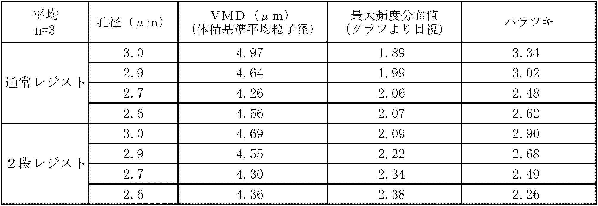
- the relationship between the pore diameter value of the produced atomizer mesh, VMD, the maximum frequency distribution of the spray particle diameter (vertex value of the frequency distribution graph), and variation was examined.
- a nebulizer mesh produced by the procedure described in Comparative Example 1 was also used (referred to as normal).
- the resist pattern 52 is a circle having a diameter of 32 ⁇ m and a thickness of 1 ⁇ m.
- the number of through holes in the atomizer mesh was the same as in Example 1.
- the hole diameter is an average value of the diameters of about 10,000 holes on the matrix 41 side of the atomizer mesh, and can be obtained by the following method. Thirty holes were randomly extracted from the SEM observation image on the matrix 41 side of the atomizer mesh, and the average value of the diameters of the holes was determined by image measurement.
- Table 1 The results are shown in Table 1. The measurement was carried out by 3 lots of meshes showing each hole diameter.
- the normal resist listed in Table 1 represents a conventional mesh produced by the method described in Comparative Example 1, and the two-stage resist represents the mesh of the present invention produced by the method described in Example 5. Show.
- the VMD of the normal resist was 4.66 to 5.26 with respect to the pore size of 3.02 to 3.05.
- the VMD of the two-stage resist was 4.59 to 4.79 for the same hole diameter.
- the VMD of the normal resist was 4.41 to 4.85.
- the two-stage VMD was 4.27 to 4.41.
- the spray particle size is uniform in the two-stage than usual. Further, the variation in lots of each hole diameter is presumed that the two-stage resist shows a smaller value than the normal resist, and the two-stage resist has a uniform spray particle diameter.
- FIG. 11 shows the maximum frequency distribution value with respect to the pore diameter. As shown in Table 2 and FIG. 11, the maximum frequency distribution value was increased by about 0.2 to 0.3 in the two-stage resist as compared with the normal resist. That is, in the two-stage resist, the peak of the frequency distribution is sharp and the spray particle diameter is considered to be uniform. For this reason, it is suggested that the two-step resist can spray more stably.
- FIG. 12 shows the dispersion of the spray particle diameter with respect to the pore diameter. As shown in FIG. 12, there was a tendency for variation to be smaller in the two-stage resist than in the normal resist. Therefore, it is considered that the two-stage resist has a uniform spray particle size.
- the mesh for a nebulizer of the present invention can be used for medical equipment such as an inhaler and beauty equipment such as a facial device.
Landscapes
- Chemical & Material Sciences (AREA)
- Engineering & Computer Science (AREA)
- Health & Medical Sciences (AREA)
- Chemical Kinetics & Catalysis (AREA)
- Electrochemistry (AREA)
- Materials Engineering (AREA)
- Metallurgy (AREA)
- Organic Chemistry (AREA)
- Anesthesiology (AREA)
- Animal Behavior & Ethology (AREA)
- Veterinary Medicine (AREA)
- Biomedical Technology (AREA)
- Heart & Thoracic Surgery (AREA)
- Hematology (AREA)
- Life Sciences & Earth Sciences (AREA)
- Public Health (AREA)
- General Health & Medical Sciences (AREA)
- Pulmonology (AREA)
- Bioinformatics & Cheminformatics (AREA)
- Dispersion Chemistry (AREA)
- Special Spraying Apparatus (AREA)
- Other Investigation Or Analysis Of Materials By Electrical Means (AREA)
Abstract
Description
1.液体を霧化して噴出するための噴霧器において液体を霧化するために使用され、複数個の貫通孔を有する噴霧器用メッシュであって、
前記貫通孔は、前記噴霧器用メッシュの一方の面が円柱空間部分を形成し、かつ他方の面がすり鉢状に広がった開口を形成してなることを特徴とする噴霧器用メッシュ。
2.前記噴霧器用メッシュが、白金を主成分とすることを特徴とする前項1に記載の噴霧器用メッシュ。
3.前記円柱空間部分の高さが0.1μm~20μmであることを特徴とする前項1または2に記載の噴霧器用メッシュ。
4.前記円柱空間部分の直径が0.3μm~10μmであることを特徴とする前項1~3のいずれか1に記載の噴霧器用メッシュ。
5.噴霧器用メッシュから噴霧される粒子の平均粒子径が1μm~15μmである前項1~4のいずれか1に記載の噴霧器用メッシュ。
6.液体を霧化して噴出するための噴霧器において液体を霧化するために使用され、複数個の貫通孔を有する噴霧器用メッシュの製造方法であって、
母型上に、1段目のレジストパターンを所定の形状に形成する第1工程と、次いで前記1段目のレジストパターン上に2段目のレジストパターンを円柱状に形成する第2工程と、前記第2工程後、金属のめっきを施し、前記噴霧器用メッシュの貫通孔を形成する第3工程と、前記母型と前記1段目および2段目のレジストパターンとを除去する第4工程とを含み、
前記第3工程により形成される貫通孔は、前記噴霧器用メッシュの一方の面が円柱空間部分を形成し、かつ他方の面がすり鉢状に広がった開口を形成してなり、前記貫通孔の円柱空間部分の形状は、前記第2工程で形成された2段目のレジストパターンの形状によって決定されることを特徴とする噴霧器用メッシュの製造方法。
7.前記噴霧器用メッシュが、白金を主成分とすることを特徴とする前項6に記載の噴霧器用メッシュの製造方法。
8.前記円柱空間部分の高さが0.1μm~20μmであることを特徴とする前項6または7に記載の噴霧器用メッシュの製造方法。
9.前記円柱空間部分の直径が0.3μm~10μmであることを特徴とする前項6~8のいずれか1に記載の噴霧器用メッシュの製造方法。
10.前記1段目のレジストパターンを形成するレジストが、ポリイミド系のレジストであり、前記2段目のレジストパターンを形成するレジストが、エポキシ系のレジストであることを特徴とする前項6~9のいずれか1に記載の噴霧器用メッシュの製造方法。
まず図4(a)に示すように、母型41を準備した。母型41としては、Cu基板を使用した。
レジストの塗布はスピンコート法により行なった。露光量は、50~100mJ/cm2とした。現像液は、化薬マイクロケム(株)製KMPR現像液を用いた。
電気めっき条件は、次の条件とした。電流密度:2A/dm2、めっき時間:70分、温度:90℃
また、円柱空間部分174の直径は、2.4μm~2.6μmであり、円柱空間部分174の長さLは、7.8μm~8.2μmであることが分かった。
噴霧器用メッシュの厚みは、20μmであった。
2段メッシュで、1段目および2段目のレジストとして共に東京応化工業(株)製商品名EPPR-Aを使用した以外は、レジストの塗布方法およびパターン形成方法は実施例1と同様にして噴霧器用メッシュを作製した。1段目のレジストパターン421円形の直径は32μm、厚みは1μmとした。また、2段目のレジストパターンの直径は2.5μm、高さは3μmとした。
2段メッシュで、1段目および2段目のレジストとして共に化薬マイクロケム(株)製商品名KMPRを使用した以外は、レジストの塗布方法およびパターン形成方法は実施例1と同様にして噴霧器用メッシュを作製した。レジストの塗布方法およびパターン形成方法は実施例1と同様に行った。1段目のレジストパターン421円形の直径は32μm、厚みは1μmとした。また、2段目のレジストパターンの直径は2.5μm、高さは3μmとした。
2段メッシュで、1段目のレジストとして東京応化工業(株)製商品名EPPR-A、2段目のレジストとして化薬マイクロケム(株)製商品名KMPRを使用した以外は、レジストの塗布方法およびパターン形成方法は実施例1と同様にして噴霧器用メッシュを作製した。1段目のレジストパターン421円形の直径は32μm、厚みは1μmとした。また、2段目レジストの高さは3μmで、2段目レジストの直径は1.5μm、2.0μm、2.5μmの3種類とした。得られたいずれの貫通孔についても、めっき後であっても貫通孔の形状は崩れることなく、良好な形状であった。
図5に示すような従来の電鋳法を用いて噴霧器用メッシュを作製した。
まず図5(a)に示すように母型51を準備した。母型51としては、Cu基板を使用した。
レジストの塗布はスピンコート法を採用した。現像液は、東京応化工業(株)EPPR現像液を用いた。露光量は、50~100mJ/cm2とした。
実施例1に記載した手順によって噴霧器用メッシュを作製した。
ただし、1段目のレジストパターン421は、直径が32μmの円形であり、厚みは1μmである。2段目のレジストパターン422は、直径が2.5μmであり、高さが6μmである円柱状である。また、噴霧器用メッシュにおける貫通孔の数は10,000個とした。

11 メッシュ
12 ケーシング
13 振動子
14 タンク
15 液体
16 メッシュ支持具
17 貫通孔
41 母型
421 1段目のレジストパターン
422 2段目のレジストパターン
43 電鋳膜
172 開口
174 円柱空間部分
Claims (10)
- 液体を霧化して噴出するための噴霧器において液体を霧化するために使用され、複数個の貫通孔を有する噴霧器用メッシュであって、
前記貫通孔は、前記噴霧器用メッシュの一方の面が円柱空間部分を形成し、かつ他方の面がすり鉢状に広がった開口を形成してなることを特徴とする噴霧器用メッシュ。 - 前記噴霧器用メッシュが、白金を主成分とすることを特徴とする請求項1に記載の噴霧器用メッシュ。
- 前記円柱空間部分の高さが0.1μm~20μmであることを特徴とする請求項1または2に記載の噴霧器用メッシュ。
- 前記円柱空間部分の直径が0.3μm~10μmであることを特徴とする請求項1~3のいずれか1項に記載の噴霧器用メッシュ。
- 噴霧器用メッシュから噴霧される粒子の平均粒子径が1μm~15μmである請求項1~4のいずれか1項に記載の噴霧器用メッシュ。
- 液体を霧化して噴出するための噴霧器において液体を霧化するために使用され、複数個の貫通孔を有する噴霧器用メッシュの製造方法であって、
母型上に、1段目のレジストパターンを所定の形状に形成する第1工程と、次いで前記1段目のレジストパターン上に2段目のレジストパターンを円柱状に形成する第2工程と、前記第2工程後、金属のめっきを施し、前記噴霧器用メッシュの貫通孔を形成する第3工程と、前記母型と前記1段目および2段目のレジストパターンとを除去する第4工程とを含み、
前記第3工程により形成される貫通孔は、前記噴霧器用メッシュの一方の面が円柱空間部分を形成し、かつ他方の面がすり鉢状に広がった開口を形成してなり、
前記貫通孔の円柱空間部分の形状は、前記第2工程で形成された2段目のレジストパターンの形状によって決定されることを特徴とする噴霧器用メッシュの製造方法。 - 前記噴霧器用メッシュが、白金を主成分とすることを特徴とする請求項6に記載の噴霧器用メッシュの製造方法。
- 前記円柱空間部分の高さが0.1μm~20μmであることを特徴とする請求項6または7に記載の噴霧器用メッシュの製造方法。
- 前記円柱空間部分の直径が0.3μm~10μmであることを特徴とする請求項6~8のいずれか1項に記載の噴霧器用メッシュの製造方法。
- 前記1段目のレジストパターンを形成するレジストが、ポリイミド系のレジストであり、前記2段目のレジストパターンを形成するレジストが、エポキシ系のレジストであることを特徴とする請求項6~9のいずれか1項に記載の噴霧器用メッシュの製造方法。
Priority Applications (4)
| Application Number | Priority Date | Filing Date | Title |
|---|---|---|---|
| EP14743039.1A EP2949357B1 (en) | 2013-01-24 | 2014-01-22 | Mesh for nebulizer, and method for manufacturing same |
| US14/763,231 US9700685B2 (en) | 2013-01-24 | 2014-01-22 | Nebulizer mesh and production method thereof |
| KR1020157020119A KR101728975B1 (ko) | 2013-01-24 | 2014-01-22 | 분무기용 메쉬 및 그 제조 방법 |
| US15/212,047 US9889261B2 (en) | 2013-01-24 | 2016-07-15 | Nebulizer mesh and production method thereof |
Applications Claiming Priority (2)
| Application Number | Priority Date | Filing Date | Title |
|---|---|---|---|
| JP2013011130A JP6006647B2 (ja) | 2013-01-24 | 2013-01-24 | 噴霧機用メッシュおよびその製造方法 |
| JP2013-011130 | 2013-01-24 |
Related Child Applications (2)
| Application Number | Title | Priority Date | Filing Date |
|---|---|---|---|
| US14/763,231 A-371-Of-International US9700685B2 (en) | 2013-01-24 | 2014-01-22 | Nebulizer mesh and production method thereof |
| US15/212,047 Division US9889261B2 (en) | 2013-01-24 | 2016-07-15 | Nebulizer mesh and production method thereof |
Publications (1)
| Publication Number | Publication Date |
|---|---|
| WO2014115771A1 true WO2014115771A1 (ja) | 2014-07-31 |
Family
ID=51227562
Family Applications (1)
| Application Number | Title | Priority Date | Filing Date |
|---|---|---|---|
| PCT/JP2014/051270 Ceased WO2014115771A1 (ja) | 2013-01-24 | 2014-01-22 | 噴霧器用メッシュおよびその製造方法 |
Country Status (5)
| Country | Link |
|---|---|
| US (2) | US9700685B2 (ja) |
| EP (1) | EP2949357B1 (ja) |
| JP (1) | JP6006647B2 (ja) |
| KR (1) | KR101728975B1 (ja) |
| WO (1) | WO2014115771A1 (ja) |
Families Citing this family (3)
| Publication number | Priority date | Publication date | Assignee | Title |
|---|---|---|---|---|
| WO2018109095A1 (en) * | 2016-12-14 | 2018-06-21 | Koninklijke Philips N.V. | Humidification of a pressurized flow of breathable gas |
| CN116829272B (zh) * | 2021-02-05 | 2025-05-23 | 东丽株式会社 | 层叠体的制造方法、高分子薄膜的制造方法及层叠体 |
| WO2026063339A1 (ja) * | 2024-09-20 | 2026-03-26 | 富士フイルム株式会社 | 電鋳用原盤、金属成形物の製造方法及び金属成形物 |
Citations (4)
| Publication number | Priority date | Publication date | Assignee | Title |
|---|---|---|---|---|
| JPH09217191A (ja) | 1996-02-15 | 1997-08-19 | Tanaka Kikinzoku Kogyo Kk | 電鋳による貴金属の精密加工方法 |
| JPH09323054A (ja) | 1996-06-05 | 1997-12-16 | Tanaka Kikinzoku Kogyo Kk | 超音波噴霧振動板 |
| JP2002059552A (ja) * | 2000-08-22 | 2002-02-26 | Ricoh Co Ltd | ノズルプレート及びその製造方法 |
| JP2003001829A (ja) * | 2001-06-27 | 2003-01-08 | Citizen Watch Co Ltd | 孔構造体とその製造方法並びにインクジェットヘッド用ノズル板とその製造方法 |
Family Cites Families (15)
| Publication number | Priority date | Publication date | Assignee | Title |
|---|---|---|---|---|
| JPS6462491A (en) | 1987-08-31 | 1989-03-08 | Nippon Seiko Kk | Formation of metallic pattern |
| US5152456A (en) | 1989-12-12 | 1992-10-06 | Bespak, Plc | Dispensing apparatus having a perforate outlet member and a vibrating device |
| US5435282A (en) * | 1994-05-19 | 1995-07-25 | Habley Medical Technology Corporation | Nebulizer |
| US20020121274A1 (en) | 1995-04-05 | 2002-09-05 | Aerogen, Inc. | Laminated electroformed aperture plate |
| US6530370B1 (en) * | 1999-09-16 | 2003-03-11 | Instrumentation Corp. | Nebulizer apparatus |
| JP4198850B2 (ja) * | 1999-11-29 | 2008-12-17 | オムロンヘルスケア株式会社 | 液体噴霧装置 |
| US6550472B2 (en) * | 2001-03-16 | 2003-04-22 | Aerogen, Inc. | Devices and methods for nebulizing fluids using flow directors |
| CA2526362C (en) * | 2003-05-20 | 2012-10-09 | James F. Collins | Ophthalmic drug delivery system |
| JP2006297226A (ja) * | 2005-04-18 | 2006-11-02 | Sumitomo Electric Ind Ltd | 噴霧器用メッシュノズルおよび噴霧器 |
| US8382008B1 (en) * | 2005-08-26 | 2013-02-26 | Jonathan J. Ricciardi | Optimized and miniaturized aerosol generator |
| US20090212133A1 (en) * | 2008-01-25 | 2009-08-27 | Collins Jr James F | Ophthalmic fluid delivery device and method of operation |
| TWI338592B (en) * | 2008-03-25 | 2011-03-11 | Ind Tech Res Inst | Nozzle plate of a spray apparatus and fabrication method thereof |
| JP2011235202A (ja) * | 2010-05-01 | 2011-11-24 | Optnics Precision Co Ltd | 霧化装置 |
| WO2012056398A1 (en) * | 2010-10-29 | 2012-05-03 | Koninklijke Philips Electronics N.V. | A nebulizer, a control unit for controlling the same, and a method of controlling a nebulizer |
| EP2644282B1 (en) * | 2012-03-28 | 2015-10-21 | Tanaka Kikinzoku Kogyo K.K. | Mesh for nebulizer and production method thereof |
-
2013
- 2013-01-24 JP JP2013011130A patent/JP6006647B2/ja active Active
-
2014
- 2014-01-22 US US14/763,231 patent/US9700685B2/en active Active
- 2014-01-22 EP EP14743039.1A patent/EP2949357B1/en active Active
- 2014-01-22 KR KR1020157020119A patent/KR101728975B1/ko active Active
- 2014-01-22 WO PCT/JP2014/051270 patent/WO2014115771A1/ja not_active Ceased
-
2016
- 2016-07-15 US US15/212,047 patent/US9889261B2/en active Active
Patent Citations (4)
| Publication number | Priority date | Publication date | Assignee | Title |
|---|---|---|---|---|
| JPH09217191A (ja) | 1996-02-15 | 1997-08-19 | Tanaka Kikinzoku Kogyo Kk | 電鋳による貴金属の精密加工方法 |
| JPH09323054A (ja) | 1996-06-05 | 1997-12-16 | Tanaka Kikinzoku Kogyo Kk | 超音波噴霧振動板 |
| JP2002059552A (ja) * | 2000-08-22 | 2002-02-26 | Ricoh Co Ltd | ノズルプレート及びその製造方法 |
| JP2003001829A (ja) * | 2001-06-27 | 2003-01-08 | Citizen Watch Co Ltd | 孔構造体とその製造方法並びにインクジェットヘッド用ノズル板とその製造方法 |
Non-Patent Citations (1)
| Title |
|---|
| See also references of EP2949357A4 |
Also Published As
| Publication number | Publication date |
|---|---|
| US20160375203A1 (en) | 2016-12-29 |
| EP2949357A1 (en) | 2015-12-02 |
| JP2014140524A (ja) | 2014-08-07 |
| US9889261B2 (en) | 2018-02-13 |
| EP2949357B1 (en) | 2023-07-26 |
| EP2949357C0 (en) | 2023-07-26 |
| US9700685B2 (en) | 2017-07-11 |
| US20150367089A1 (en) | 2015-12-24 |
| KR20150102082A (ko) | 2015-09-04 |
| JP6006647B2 (ja) | 2016-10-12 |
| EP2949357A4 (en) | 2016-10-05 |
| KR101728975B1 (ko) | 2017-04-20 |
Similar Documents
| Publication | Publication Date | Title |
|---|---|---|
| JP6835991B2 (ja) | ネブライザのための開口板を製造する方法 | |
| JP4500477B2 (ja) | 改良されたアパーチャプレートならびにその構築および使用のための方法 | |
| EP2886185A1 (en) | Perforated membrane and process for its preparation | |
| US11872573B2 (en) | Method for producing an aperture plate | |
| JP6006647B2 (ja) | 噴霧機用メッシュおよびその製造方法 | |
| JP6244318B2 (ja) | 噴霧機用メッシュおよびその製造方法 | |
| CN104302813B (zh) | 气溶胶发生器 | |
| JP5157000B1 (ja) | 噴霧器用メッシュ | |
| JP2013202409A (ja) | 噴霧器用メッシュの製造方法 | |
| EP2947181B1 (en) | A method for producing an aperture plate | |
| JP2024017207A (ja) | 噴霧装置用メッシュ部材及び超音波液体噴霧装置 | |
| HK1205770B (en) | Aerosol generators | |
| HK1205770A1 (en) | Aerosol generators | |
| CN116511737A (zh) | 一种雾化器用耐腐蚀金属锆网及其制备方法 | |
| HK1205771B (zh) | 制造用於喷雾器的孔板的方法 | |
| HK1190367A1 (zh) | 光限定孔板以及其制备方法 | |
| HK1190367B (en) | Photodefined aperture plate and method for producing the same |
Legal Events
| Date | Code | Title | Description |
|---|---|---|---|
| 121 | Ep: the epo has been informed by wipo that ep was designated in this application |
Ref document number: 14743039 Country of ref document: EP Kind code of ref document: A1 |
|
| ENP | Entry into the national phase |
Ref document number: 20157020119 Country of ref document: KR Kind code of ref document: A |
|
| NENP | Non-entry into the national phase |
Ref country code: DE |
|
| WWE | Wipo information: entry into national phase |
Ref document number: 14763231 Country of ref document: US Ref document number: 2014743039 Country of ref document: EP |