WO2014122737A1 - サクションロール装置 - Google Patents
サクションロール装置 Download PDFInfo
- Publication number
- WO2014122737A1 WO2014122737A1 PCT/JP2013/052742 JP2013052742W WO2014122737A1 WO 2014122737 A1 WO2014122737 A1 WO 2014122737A1 JP 2013052742 W JP2013052742 W JP 2013052742W WO 2014122737 A1 WO2014122737 A1 WO 2014122737A1
- Authority
- WO
- WIPO (PCT)
- Prior art keywords
- negative pressure
- rotating body
- suction roll
- conduction
- outer layer
- Prior art date
- Legal status (The legal status is an assumption and is not a legal conclusion. Google has not performed a legal analysis and makes no representation as to the accuracy of the status listed.)
- Ceased
Links
Images


Classifications
-
- B—PERFORMING OPERATIONS; TRANSPORTING
- B65—CONVEYING; PACKING; STORING; HANDLING THIN OR FILAMENTARY MATERIAL
- B65H—HANDLING THIN OR FILAMENTARY MATERIAL, e.g. SHEETS, WEBS, CABLES
- B65H20/00—Advancing webs
- B65H20/12—Advancing webs by suction roller
-
- B—PERFORMING OPERATIONS; TRANSPORTING
- B65—CONVEYING; PACKING; STORING; HANDLING THIN OR FILAMENTARY MATERIAL
- B65H—HANDLING THIN OR FILAMENTARY MATERIAL, e.g. SHEETS, WEBS, CABLES
- B65H23/00—Registering, tensioning, smoothing or guiding webs
- B65H23/04—Registering, tensioning, smoothing or guiding webs longitudinally
- B65H23/06—Registering, tensioning, smoothing or guiding webs longitudinally by retarding devices, e.g. acting on web-roll spindle
- B65H23/10—Registering, tensioning, smoothing or guiding webs longitudinally by retarding devices, e.g. acting on web-roll spindle acting on running web
- B65H23/14—Tensioning rollers applying braking forces
-
- B—PERFORMING OPERATIONS; TRANSPORTING
- B65—CONVEYING; PACKING; STORING; HANDLING THIN OR FILAMENTARY MATERIAL
- B65H—HANDLING THIN OR FILAMENTARY MATERIAL, e.g. SHEETS, WEBS, CABLES
- B65H23/00—Registering, tensioning, smoothing or guiding webs
- B65H23/04—Registering, tensioning, smoothing or guiding webs longitudinally
- B65H23/24—Registering, tensioning, smoothing or guiding webs longitudinally by fluid action, e.g. to retard the running web
- B65H23/245—Suction retarders
-
- B—PERFORMING OPERATIONS; TRANSPORTING
- B65—CONVEYING; PACKING; STORING; HANDLING THIN OR FILAMENTARY MATERIAL
- B65H—HANDLING THIN OR FILAMENTARY MATERIAL, e.g. SHEETS, WEBS, CABLES
- B65H27/00—Special constructions, e.g. surface features, of feed or guide rollers for webs
-
- B—PERFORMING OPERATIONS; TRANSPORTING
- B65—CONVEYING; PACKING; STORING; HANDLING THIN OR FILAMENTARY MATERIAL
- B65H—HANDLING THIN OR FILAMENTARY MATERIAL, e.g. SHEETS, WEBS, CABLES
- B65H2401/00—Materials used for the handling apparatus or parts thereof; Properties thereof
- B65H2401/10—Materials
- B65H2401/14—Textiles, e.g. woven or knitted fabrics
-
- B—PERFORMING OPERATIONS; TRANSPORTING
- B65—CONVEYING; PACKING; STORING; HANDLING THIN OR FILAMENTARY MATERIAL
- B65H—HANDLING THIN OR FILAMENTARY MATERIAL, e.g. SHEETS, WEBS, CABLES
- B65H2401/00—Materials used for the handling apparatus or parts thereof; Properties thereof
- B65H2401/20—Physical properties, e.g. lubricity
- B65H2401/242—Porosity
-
- B—PERFORMING OPERATIONS; TRANSPORTING
- B65—CONVEYING; PACKING; STORING; HANDLING THIN OR FILAMENTARY MATERIAL
- B65H—HANDLING THIN OR FILAMENTARY MATERIAL, e.g. SHEETS, WEBS, CABLES
- B65H2403/00—Power transmission; Driving means
- B65H2403/70—Clutches; Couplings
- B65H2403/72—Clutches, brakes, e.g. one-way clutch +F204
- B65H2403/725—Brakes
- B65H2403/7255—Disc brakes
-
- B—PERFORMING OPERATIONS; TRANSPORTING
- B65—CONVEYING; PACKING; STORING; HANDLING THIN OR FILAMENTARY MATERIAL
- B65H—HANDLING THIN OR FILAMENTARY MATERIAL, e.g. SHEETS, WEBS, CABLES
- B65H2404/00—Parts for transporting or guiding the handled material
- B65H2404/50—Surface of the elements in contact with the forwarded or guided material
- B65H2404/53—Surface of the elements in contact with the forwarded or guided material with particular mechanical, physical properties
- B65H2404/531—Surface of the elements in contact with the forwarded or guided material with particular mechanical, physical properties particular coefficient of friction
-
- B—PERFORMING OPERATIONS; TRANSPORTING
- B65—CONVEYING; PACKING; STORING; HANDLING THIN OR FILAMENTARY MATERIAL
- B65H—HANDLING THIN OR FILAMENTARY MATERIAL, e.g. SHEETS, WEBS, CABLES
- B65H2406/00—Means using fluid
- B65H2406/30—Suction means
- B65H2406/33—Rotary suction means, e.g. roller, cylinder or drum
- B65H2406/331—Rotary suction means, e.g. roller, cylinder or drum arranged for rotating while moving along material to be handled, e.g. rolling on material
-
- B—PERFORMING OPERATIONS; TRANSPORTING
- B65—CONVEYING; PACKING; STORING; HANDLING THIN OR FILAMENTARY MATERIAL
- B65H—HANDLING THIN OR FILAMENTARY MATERIAL, e.g. SHEETS, WEBS, CABLES
- B65H2406/00—Means using fluid
- B65H2406/30—Suction means
- B65H2406/33—Rotary suction means, e.g. roller, cylinder or drum
- B65H2406/332—Details on suction openings
-
- B—PERFORMING OPERATIONS; TRANSPORTING
- B65—CONVEYING; PACKING; STORING; HANDLING THIN OR FILAMENTARY MATERIAL
- B65H—HANDLING THIN OR FILAMENTARY MATERIAL, e.g. SHEETS, WEBS, CABLES
- B65H2701/00—Handled material; Storage means
- B65H2701/10—Handled articles or webs
- B65H2701/17—Nature of material
- B65H2701/173—Metal
Definitions
- the present invention relates to a suction roll device. More specifically, the present invention relates to a suction roll device that can sufficiently grasp and convey or brake various long materials without damaging them, and can reliably wind them.
- each material is wound in a coil shape around a core material and shipped in a stacked state.
- a metal plate can be used as a material for various products such as automobiles, home appliances, building materials, steel furniture, electricity, and electronic components.
- the metal plate varies in width and thickness depending on the application, and the plate thickness ranges from a metal foil of about several ⁇ m to a thickness of several mm.
- the width of the metal plate ranges from a thin strip having a slit width of about several millimeters to a metal plate coil base material before cutting that exceeds a width of 2 m.
- a slitter line for cutting a wide metal plate coil base material so as to have a constant width in the longitudinal direction and winding it as a multi-strip strip is used. Yes.
- the strip means the unit of the number of strips.
- the slitter line draws a wide metal plate coil base material from the rotating roll, cuts the strip to a desired width by the slitter, and processes it again as a metal strip coil by winding it around the rotating recoiler roll. It is a device.
- a tension pad system for example, Patent Document 1
- a roll tension system for example, Patent Document 2
- Patent Document 3 proposes a winding tension applying device.
- Patent Document 3 describes a winding tension applying device 100 shown in FIG.
- the winding tension applying device 100 includes a tension pad 101 that presses a metal strip from above and below to apply tension.
- elastic rolls 102 and 103 for applying a back tension made of a close-contact laminated product of a large number of rubber-like thin elastic disks are arranged before and after the tension pad.
- the winding tension applying device 100 applies a sufficient winding tension to the multi-strand metal strip by a combination of the tension pad 101 and the back tension applying elastic rolls 102 and 103.
- a sheet-like material formed of paper or resin is a material provided to a printing machine, a packaging machine, a coating machine, or the like.
- a suction roll device exists as a device for gripping and conveying.
- the suction roll device adsorbs a sheet-like material to the outer peripheral surface of a rotating roll and grips and conveys a long material.
- the suction roll device has a region that generates negative pressure, and generates suction force by the negative pressure.
- the suction roll device includes a device in which the outer peripheral surface of the roll is made of a porous material so that no traces of adsorption are left on the sheet-like material to be conveyed.
- the outer peripheral surface of the roll is made of a porous material so that no traces of adsorption are left on the sheet-like material to be conveyed.
- Patent Document 4 describes a suction roll device 200 shown in FIG.
- the suction roll device 200 includes a central shaft 202 supported by an opposing support frame 201 and a cylindrical porous body 203 having air permeability.
- a plurality of air passages are formed between the central shaft 202 and the cylindrical porous body 203 at predetermined intervals in the circumferential direction.
- a suction port 205 is formed to face one end opening 204 of some of the plurality of ventilation paths.
- a pressure port 207 facing the other end opening 206 of some of the air passages that are not in communication with the suction port 205 is formed.
- the negative pressure formed on the suction port 205 side is guided to the air passage, and an adsorption force is generated on the outer peripheral surface of the cylindrical porous body 203 at the outer portion of the air passage. Further, the positive pressure formed on the pressurizing port 207 side is guided to the air passage, is released to the outside through the cylindrical porous body 203, and discharges dust and the like adhering to the fine holes to the outside. .
- suction roll devices there is a device that can adjust the suction width in accordance with the width of the sheet-like material.
- a suction roll device described in Patent Document 5 there is a suction roll device described in Patent Document 5.
- Patent Document 5 describes a suction roll device 300 shown in FIG.
- the suction roll device 300 has a rotatable outer cylinder 301 and a fixed inner cylinder 302.
- a drive shaft 303 having an air inlet is provided inside the inner cylinder 302, and a partition plate 304 that is movable in the axial direction within the inner cylinder is formed.
- the suction roll device 300 can adjust the range in which air is sucked from the opening 305 by moving the partition plate 304 within the inner cylinder by the rotation of the drive shaft 303.
- JP 2005-262310 A JP-A-5-253615 JP-A-6-238329 JP 2008-137804 A Japanese Patent Laid-Open No. 7-127631 JP 2004-230449 A JP 2012-81477 A
- the belt has different friction coefficients on the inside and outside of the belt, and uniform tension can be applied to each strip. Further, since the belt surface and the belt plate rotate and move without slipping, the surface of the belt plate is hardly scratched.
- the multi-strip belts are arranged at predetermined intervals. For example, for an ultra-thin plate having a strip thickness of less than 0.1 mm, the belt The trace of the edge of an edge part may adhere to the strip surface.
- the metal strip may fall into the gap between the belts, resulting in inconvenience that sufficient tension cannot be applied.
- a uniform strip tension can be applied to a multi-band strip without damaging the surface of the metal strip, particularly a thin strip.
- a winding tension can be sufficiently applied to a narrow strip.
- the suction roll device described in Patent Document 4 can generate a negative pressure capable of transporting thin and light objects such as paper and film, but has a sufficient winding tension for a heavy material such as a metal strip. It does not produce negative pressure to give. That is, a large negative pressure is not generated and it cannot be used as a winding tension applying device.
- the cylindrical porous body is formed of ceramic. Since the friction coefficient of ceramic is small, a sufficient friction force is not generated between the outer peripheral surface of the ceramic and the metal strip. That is, the winding tension cannot be applied to the metal strip using the frictional engagement.
- the suction width of the suction roll cannot be controlled by the width of the sheet-like material. That is, when the width of the sheet-like material is narrower than the suction width of the roll, air is sucked from the vent hole deviating from the width of the sheet-like material. As a result, the sheet-like material is not sufficiently adsorbed on the surface of the suction roll, and the gripping force is insufficient, causing a conveyance failure.
- the suction roll device described in Patent Document 5 is capable of adjusting the suction width in accordance with the width of the sheet-like material, but for an object that is arranged like a multi-strand metal strip. On the other hand, a sufficient negative pressure cannot be generated.
- the present invention was devised in view of the above points, and is a suction roll device that can sufficiently grip and convey or brake various long materials without damaging them, and can reliably wind them up.
- the purpose is to provide.
- a suction roll device of the present invention includes a rotating body main body configured to be rotatable, and a continuity in which a negative pressure is formed by a predetermined suction device provided inside the rotating body main body.
- a rotating body having a hole, a conductive groove formed on a surface of the rotating body main body and connected to the conductive hole, a braking portion for suppressing rotation of the rotating body main body, and an outside of all the conductive grooves And a low air permeability outer layer portion having elasticity and having a coefficient of friction equal to or greater than a predetermined value.
- the rotating body is provided inside the rotating body and has a conduction hole in which a negative pressure is formed by a predetermined suction device, whereby the inside of the rotating body can be set to a negative pressure.
- a predetermined suction device for example, a vacuum pump, an ejector, or the like can be used as the predetermined suction device.
- the rotating body is formed on the surface of the rotating body main body and has the conduction groove connected to the conduction hole, the conduction groove and the conduction hole are connected, and the negative pressure region generated in the conduction hole is rotated. Can be extended to the surface of the body.
- the rotating body is formed on the surface of the rotating body main body and has the conductive groove connected to the conductive hole, the negative pressure region can be widened by the conductive groove. That is, it becomes possible to apply a negative pressure to the end of the roll away from the introduction hole inside the apparatus.
- the rotating body has a conduction hole in which negative pressure is formed by a predetermined suction device and a conduction groove formed on the surface of the rotating body main body and connected to the conduction hole, thereby contacting the surface of the rotating body main body. It will exert a negative pressure on the object and can be adsorbed.
- suction by a negative pressure here originates in the press by the air
- the object in contact with the surface refers to, for example, a long metal strip.
- a rotating body having a conduction hole formed on the surface of the rotating body main body and having a conduction groove connected to the conduction hole and formed on the surface of the rotating body with a negative pressure generated by a predetermined suction device, and provided outside all the conduction grooves.
- a desired braking force can be generated for the rotation of the rotating body.
- the object in contact with the apparatus is frictionally engaged, and strong between the object.
- a frictional force can be generated.
- a frictional resistance force in the direction opposite to the traveling direction can be exerted on the metal strip.
- the rotating body body can be rotated by frictional force by having a rotating body body configured to be rotatable and an outer layer portion that is provided outside all the conductive grooves and has a friction coefficient equal to or greater than a predetermined value. it can. That is, the rotating body main body is rotated by the frictional force generated when the object to be wound comes into contact with the apparatus.
- a braking part that suppresses the rotation of the rotating body and a low-breathing outer layer part that is provided outside all the conductive grooves and has a coefficient of friction equal to or greater than a predetermined value.
- a winding tension can be applied. That is, the object receives an adsorption force due to a negative pressure, and a braking force is applied to the rotation of the rotating body. Thereby, the frictional force generated between the object and the outer layer portion becomes the winding tension for the object to be wound.
- the braking force applied to the rotating body main body is adjusted by including a braking portion that suppresses the rotation of the rotating body main body and an outer layer portion that is provided outside all the conductive grooves and has a friction coefficient equal to or greater than a predetermined value. And the winding tension exerted on the object in contact with the apparatus can be adjusted.
- the rotating body has a braking part that suppresses the rotation of the rotating body and a low-breathing outer layer part that is provided outside all the conductive grooves and has a coefficient of friction equal to or greater than a predetermined value. Sufficient winding tension can be given to it. That is, the negative pressure inside the device is increased, and the winding tension on the object can be increased by increasing the braking force.
- the outer layer portion having elasticity provided outside all the conductive grooves it is possible to make the surface of an object in contact with the device, for example, a material coated or plated on the surface difficult to be damaged.
- the rotating body main body can be rotated independently.
- the apparatus when the apparatus is used for gripping and conveying a wide sheet-like object formed of paper, resin, or the like, the sheet-like substance can be reliably conveyed.
- the apparatus when the apparatus is arranged on the slitter line, a metal strip that is in contact with the apparatus can be gripped and conveyed.
- a clutch for detaching the drive unit and the rotating body main body it is possible to quickly switch between transmitting or stopping the driving force to the rotating body main body. For example, if you want to apply winding tension from the middle while gripping and transporting an object in contact with the device, disengage the clutch to disconnect the drive unit and quickly switch to a state where only the braking unit works on the rotating body. be able to.
- the rotating body when configured to be able to adjust the amount of air flowing through the conduction hole, the negative pressure inside the device can be adjusted. That is, it is possible to adjust the winding tension applied to the object and to apply an appropriate winding tension corresponding to the width and thickness of the object.
- the negative pressure generated in the conduction groove is reduced by the plurality of vent holes. Can be affected. Thereby, a negative pressure can be efficiently generated in the outer layer portion.
- the intermediate cylinder portion has at least one vent hole groove portion formed in the radial direction around the vent hole, the air around the vent hole is sucked in, and the negative pressure generation area is widened, thereby The internal negative pressure can be further increased.
- the rotating body when the rotating body is formed in a substantially cylindrical shape, a plurality of conduction holes are formed in the circumferential direction of the rotating body, and a plurality of conduction grooves are formed in the longitudinal direction of the rotating body, A negative pressure can be continuously applied to the contacting object. That is, a suction force due to a negative pressure is continuously generated on the surface of the rotating body.
- the rotating body is formed in a substantially cylindrical shape, a plurality of conduction holes are formed in the circumferential direction of the rotating body, adjacent conduction holes are spaced apart from each other, and the conduction groove is the longitudinal length of the rotation body.
- a plurality of conductive grooves are formed in the direction and adjacent conductive grooves have a constant interval, variations in adsorption force on the surface of the apparatus can be suppressed. That is, since the adjacent conduction holes and conduction grooves are not communicated with each other, it is possible to suppress the state in which only air at a position close to the suction device is sucked and to generate negative pressure evenly at the end of the rotating body. .
- the total cross-sectional area of the conduction hole and the total cross-sectional area of the conduction groove are formed approximately the same for the rotating body, the phenomenon of sucking air from a location close to the conduction hole is less likely to occur.
- the negative pressure can be generated evenly over the whole. That is, it is possible to suppress variations in adsorption force on the surface of the apparatus.
- the total cross-sectional area referred to here is the sum of the cross-sectional areas of surfaces that are substantially perpendicular to the surface direction of the apparatus.
- the air permeability of the outer layer portion can be easily adjusted. That is, when it is desired to increase the negative pressure inside the apparatus, it is possible to cope with the problem by using a very low air permeability nonwoven fabric or by stacking a plurality of nonwoven fabrics to form a multilayer structure.
- the outer layer portion is formed of a low-breathable nonwoven fabric, it becomes possible to easily replace the outer layer portion when the nonwoven fabric surface is soiled or clogged, thereby facilitating maintenance of the device. can do.
- the air permeability of the outer layer portion is 0.2 cm 3 / cm 2 ⁇ s or less in terms of Frazier air permeability, the outer layer portion is difficult to inhale excess outside air. As a result, the negative pressure inside the apparatus becomes sufficiently high, and a sufficient winding tension can be applied to the object.
- the suction roll device of the present invention is provided with a rotating body main body configured to be rotatable, and a negative pressure is formed by a predetermined suction device provided inside the rotating body main body.
- a rotating body having a conduction hole formed on the surface of the rotating body main body and connected to the conduction hole, a drive unit for rotating the rotating body main body, and the outside of all the conduction grooves And a low air permeability outer layer portion having elasticity and having a coefficient of friction equal to or greater than a predetermined value.
- the rotating body comes into contact with the surface of the rotating body by forming a conducting hole in which a negative pressure is formed by a predetermined suction device and a conducting groove formed on the surface of the rotating body and connected to the conducting hole.
- a negative pressure is exerted on the object and can be adsorbed.
- the object in contact with the surface here refers to a wide sheet-like object formed of, for example, paper or resin.
- the rotating body main body configured to be rotatable, a conduction hole provided inside the rotating body main body and forming a negative pressure by a predetermined suction device, and formed on the surface of the rotating body main body and conducting.
- the suction roll device according to the present invention can sufficiently grip and convey or brake various long materials without damaging them, and can reliably wind them.
- FIGS. 2A and 2B are a cross-sectional view taken along a line AA and a cross-sectional view taken along a line BB in the schematic view shown in FIG. It is the schematic sectional drawing (a) of the position corresponding to the negative pressure conduction
- FIG. 6A is a schematic view showing an example of arranging the suction roll device on the slitter line winding side
- FIG. 5B is a schematic view showing another arrangement example.
- FIG. 1 It is the schematic sectional drawing (a) of the suction roll apparatus which has a 90-degree negative pressure area
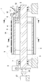
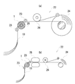
- FIG. 1 is a schematic view showing an example of a suction roll device to which the present invention is applied.
- 2 is an AA sectional view (a) and a BB sectional view (b) of the schematic diagram shown in FIG.
- FIG. 3 is a schematic sectional drawing (a) of the position corresponding to the negative pressure conduction
- FIG. 4 is a schematic diagram (a) showing an inner cylinder, a schematic diagram (b) showing an intermediate cylinder, and a schematic diagram (c) showing a vent hole groove provided around the vent hole.
- FIG. 5 is the schematic (a) which shows the intermediate
- FIG. 6 is a cross-sectional view (a) showing details of the X portion of FIG. 1 and a cross-sectional view CC of the cross-sectional view (a).
- FIG. 7 is a cross-sectional view corresponding to FIG.
- FIG. 8 is a view showing an enlarged micrograph of the nonwoven fabric used in the suction roll device to which the present invention is applied.
- FIG. 9 is an enlarged micrograph of a general nonwoven fabric.
- FIG. 10 is an enlarged micrograph of the high-density woven fabric.
- FIG. 11 is an enlarged micrograph of a general woven fabric.
- a negative pressure roll 1 which is an example of a suction roll device to which the present invention is applied includes a rotating shaft 2, an inner cylinder 3, an intermediate cylinder 4, and a multiple nonwoven fabric laminated outer layer 5.
- the rotating shaft 2 is a member that becomes the center of rotation of the negative pressure roll 1, and is connected to the inner cylinder 3 by a reinforcing disk 9.
- the inner cylinder 3 has a cylindrical shape and rotates together with the rotating shaft 2.
- the rotating shaft 2 and the inner cylinder 3 correspond to the rotating body main body.
- the intermediate cylinder 4 is a cylindrical tube formed outside the inner cylinder 3, and rotates in conjunction with the rotary shaft 2 and the inner cylinder 3.
- the multiple nonwoven fabric laminated outer layer 5 is formed on the outer side of the intermediate cylinder 4 and is a portion where the negative pressure roll 1 and the metal strip 13 are in contact. The multiple nonwoven fabric laminated outer layer 5 also rotates in conjunction with the rotating shaft 2, the inner cylinder 3 and the intermediate cylinder 4.
- the negative pressure roll 1 has a braking device 6 that suppresses the rotation of the negative pressure roll 1. Further, the negative pressure roll 1 has bearing portions 7 that support the rotary shaft 2 at both ends of the rotary shaft 2.
- the negative pressure roll 1 does not necessarily need to be composed of the rotating shaft 2, the inner cylinder 3, the intermediate cylinder 4, and the multiple nonwoven fabric laminated outer layer 5.
- the negative pressure roll 1 is preferably composed of a rotating shaft 2, an inner cylinder 3, an intermediate cylinder 4, and a multiple nonwoven fabric laminated outer cylinder 5 from the viewpoint that manufacturing and maintenance are facilitated by being divided into each member.
- the rotating body is composed of the rotating shaft 2, the inner cylinder 3, and the reinforcing disk 9.
- the rotating body body is composed of the rotating shaft 2, the inner cylinder 3, and the reinforcing disk 9 because it can have a strength that can withstand the tension. Is preferred.
- the rotating shaft 2, the inner cylinder 3, and the reinforcement disk 9 are integrally formed of the same metal, it is more preferable because the strength can be further increased.
- the inner cylinder 3 does not have a cylindrical shape, but may be machined from a solid material to form a negative pressure roll 1 integrated with the rotary shaft 2.
- the material of the rotating shaft 2 and the inner cylinder 3 is not particularly limited. For example, it is possible to reduce the manufacturing cost by using a plastic material.
- middle cylinder 4, and the multiple nonwoven fabric laminated outer layer 5 is not limited, Each becomes the structure which can be rotated integrally in the same direction. That is enough. That is, the members may be connected by a fixing tool, or a structure in which the members are rotated integrally by friction engagement between the members by a frictional force may be employed.
- the type of the bearing portion 7 is not particularly limited.
- it can be set as the bearing part 7 of a ball bearing.
- it is preferable to employ a rolling bearing, a plain bearing, or the like for the bearing portion 7.
- the structure and type of the braking device 6 are not particularly limited, and it is sufficient if the rotation of the negative pressure roll 1 can be suppressed.
- the braking device 6 for example, a disc brake, a water-cooled pneumatic brake, an electric motor type, a hydraulic type brake, or the like can be used.
- the negative pressure roll 1 has an electric motor 27.
- the electric motor 27 is detachably connected to the rotary shaft 2 via a detachable joint 28 and rotates the rotating body.
- the negative pressure roll 1 does not necessarily need to have the electric motor 27.
- a sheet made of paper, resin, or the like that allows the metal strip 13 to be conveyed to the winder by operating the electric motor 27 after holding the metal strip 13 after the slit by negative pressure adsorption.
- the negative pressure roll 1 preferably has an electric motor 27 from the viewpoint that it can be used as a gripping and conveying suction roll even in a processing line for shaped objects.
- the electric motor 27 does not necessarily need to be detachably connected to the rotary shaft 2 via the detachable joint 28. However, it is preferable that the electric motor 27 is detachably connected to the rotary shaft 2 via the detachable joint 28 from the point that the transmission or stop of the driving force to the rotating body can be quickly switched.
- a negative pressure conduction hole 8 penetrating the inner cylinder 3 is formed on one end side of the inner cylinder 3.
- the negative pressure conduction hole 8 serves as an air flow path when air inside the negative pressure roll 1 is drawn by a vacuum pump. Further, a plurality of the negative pressure conduction holes 8 are formed at regular intervals in the circumferential direction of the inner cylinder 3.
- the arrow Z indicates the direction in which the negative pressure roll 1 is sucked by the vacuum pump.
- a large-capacity exhaust blower as a suction device as in the prior art suction roll device.
- a vacuum pump or an ejector that generates a high degree of vacuum with a relatively small suction amount is used. Can be used.
- a negative pressure conduction groove 14 connected to the negative pressure conduction hole 8 is provided on the surface of the inner cylinder 3.
- the negative pressure conduction groove 14 is formed in the longitudinal direction of the negative pressure roll 1 and generates a negative pressure up to the end of the negative pressure roll 1.
- a negative pressure conduction portion 10 is provided on the rotary shaft 2 side of the negative pressure roll 1 so as to communicate with the negative pressure conduction hole 8.
- the negative pressure conducting part 10 is connected to a vacuum pump and plays a role of an inlet for making the inside of the negative pressure roll 1 have a negative pressure.
- the negative pressure conducting portion 10 is connected and fixed to the bearing portion 7 and improves the airtightness inside the negative pressure roll 1 while being in contact with the negative pressure conducting hole 8 that rotates together with the rotating shaft 2.
- a negative pressure adjusting valve 11 and a negative pressure gauge 12 are provided in connection with the negative pressure conducting portion 10.
- the negative pressure adjusting valve 11 is a valve that adjusts the amount of air flowing through the negative pressure conducting unit 10.
- the negative pressure conduction holes 8 can form a negative pressure inside the negative pressure roll 1, and the number and positions of the negative pressure conduction holes 8 are not particularly limited. However, it is preferable that the negative pressure introduction holes 8 are arranged at equal intervals in the circumferential direction of the inner cylinder 3 from the viewpoint of continuously applying a negative pressure to the rotating negative pressure roll 1.
- the negative pressure conduction hole 8 is not necessarily formed only on one end side of the inner cylinder 3.
- the negative pressure conduction hole 8 and the flow path of the vacuum pump are provided on both sides of the inner cylinder 3, and the internal air is drawn from both ends of the negative pressure roll 1. May be.
- the negative pressure conducting portion 10 is not necessarily provided, and it is sufficient if the negative pressure roll 1 has a structure capable of forming a negative pressure, and other known techniques may be used. However, it is preferable that the negative pressure conduction part 10 is provided in terms of improving the airtightness inside the negative pressure roll 1.
- the negative pressure conduction part 10 does not necessarily need to be connected to the bearing part 7. However, it is preferable that the negative pressure conduction part 10 is connected to the bearing part 7 in that the negative pressure conduction part 10 is fixed and the airtightness between the negative pressure introduction hole 8 is easily improved.
- the negative pressure roll 11 is not necessarily provided with the negative pressure adjusting valve 11 and the negative pressure gauge 12. However, it is preferable that the negative pressure roll 1 is provided with a negative pressure adjusting valve 11 and a negative pressure gauge 12 because the negative pressure inside the roll can be confirmed and the negative pressure can be easily adjusted.
- the one end side of the negative pressure roll 1 has a cross section as shown in FIG.
- a negative pressure conduction portion 10 and a negative pressure conduction hole 8 are provided on one end side of the negative pressure roll 1.
- the negative pressure conduction part 10 is formed in a region occupying approximately 90 degrees on the circumference of the negative pressure roll.
- the negative pressure roll 1 is in contact with the metal strip 13 at a position corresponding to the negative pressure conducting portion 10.
- 2A is an enlarged view of the surface area of the negative pressure roll 1.
- the negative pressure roll 1 in the area
- the negative pressure conduction part 10 does not necessarily have to be formed in a region occupying approximately 90 degrees on the circumference of the negative pressure roll.
- the negative pressure roll can be arranged so that the negative pressure roll comes into contact with the metal strip rising in the vertical direction from below, and the metal strip is then pulled in the horizontal direction. Is preferably formed in a region occupying approximately 90 degrees on the circumference of the negative pressure roll.
- FIG. 3A is a view showing the structure of another example of the suction roll device.
- partition protrusions 15 are provided on the surface of the inner cylinder 3, and negative pressure conduction grooves 14 are formed between the partition protrusions 15.
- the negative pressure conduction groove 14 can be formed as a layer different from the inner cylinder 3.
- the partition projection 15 is in close contact with the inner cylinder 3 and the intermediate cylinder 4, so that the airtightness of the negative pressure conduction groove 14 can be improved. it can.
- FIG. 3B is a view showing the structure of still another example of the suction roll device.
- the apparatus shown in FIG. 3B has a structure in which the intermediate cylinder 4 does not exist.
- the apparatus shown in FIG. 3B has a rotating body main body 32. If a negative pressure can be applied to the metal strip, such a simplified structure can be adopted.
- the inner cylinder 3 is provided with a plurality of negative pressure conduction holes 8 and negative pressure conduction grooves 14.
- the right side of FIG. 4A is one end side of the negative pressure roll 1, and when the vacuum pump is operated, negative pressure is also applied to the negative pressure conduction hole 8 and the negative pressure conduction groove 14 via the negative pressure conduction portion 10. The resulting structure. Further, the negative pressure is applied by the negative pressure conduction groove 14 to the end opposite to the side where the negative pressure conduction hole 8 is provided.
- the intermediate cylinder 4 is provided outside the inner cylinder 3.
- the intermediate cylinder 4 is formed of a pipe material made of metal, synthetic resin, hard rubber, or the like, and a large number of ventilation holes 16 are provided on the surface thereof.
- the vent holes 16 are positioned at regular intervals in the longitudinal direction and the circumferential direction of the intermediate cylinder 4, and air flows from the vent holes 16 to the negative pressure conduction grooves 14, thereby generating a negative pressure.
- vent hole groove portion 17 formed in four directions is provided around the vent hole 16. The range of air sucked into the vent hole 16 is expanded by the vent hole groove portion 17.
- cross-sectional area of all of the negative pressure conduction holes 8 and the cross-sectional area of all of the negative pressure conduction grooves 14 are formed to be substantially equal. Further, the cross-sectional area of all the negative pressure conduction holes 8 and the cross-sectional area of all the vent holes 16 are formed to be substantially equal.
- the intermediate cylinder 4 and the vent hole 16 are not necessarily formed, and it is sufficient if a negative pressure can be applied to the metal strip. However, it is preferable that the intermediate cylinder 4 and the vent holes 16 are formed in that the negative pressure can be efficiently generated in the outer layer 15 of the nonwoven fabric by forming the intermediate cylinder 4 and providing the vent holes 16.
- vent hole groove portion 17 is not necessarily provided around the vent hole 16. However, it is preferable that the vent hole groove portion 17 is provided around the vent hole 16 in that the negative pressure generation area is widened to further increase the negative pressure degree inside the negative pressure roll 1.
- the shape of the vent groove portion is not particularly limited, and the number of the grooves can be increased as shown in FIG. 4C to form the vent hole groove portion 18 formed in eight directions.
- the cross-sectional area of all the negative pressure conduction holes 8 and the cross-sectional area of all the negative pressure conduction grooves 14 be substantially equal.
- the cross-sectional area of all of the negative-pressure conduction holes 8 and the cross-sectional area of all of the negative-pressure conduction grooves 14 are substantially equal.
- it is formed. From the same point, it is more preferable that the cross-sectional area of all of the negative pressure conduction holes 8 and the cross-sectional area of all of the vent holes 16 are substantially equal.
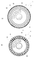
- FIG. 5A shows an intermediate cylinder 4 formed of a punching metal 19 as another example of the intermediate cylinder 4.
- the punching metal 19 is a material in which a large number of small-diameter holes 31 are formed by punching a flat metal plate.
- FIG. 5B shows the small diameter hole 31 formed in the punching metal 19.
- the small-diameter hole 31 allows air to flow through the negative pressure conduction groove 14, as with the vent hole 16, but is smaller than the vent hole 16.
- a commercially available punching metal 19 can also be used.
- the vertical cross-sectional area of the row of negative pressure conduction grooves 14 and the total hole area of the small-diameter holes 31 of the punching metal positioned on the negative pressure conduction grooves 14 are formed to be substantially equal to each other. It becomes possible to generate a negative pressure equally over the whole of 1.
- the multiple nonwoven fabric laminated outer layer 5 is provided outside the intermediate cylinder 4.
- the multi-layered nonwoven fabric outer layer 5 is formed by laminating a plurality of low-breathable nonwoven fabrics 20 and has a permeability of 0.2 cm 3 / cm 2 ⁇ s or less in terms of Frazier-type air permeability.
- the nonwoven fabric 20 has an appropriate coefficient of friction and elasticity, generates a sufficient frictional force with the metal strip 13, and is hardly damaged even when in contact with the metal strip. .
- the multi-layered nonwoven fabric laminated outer layer 5 is formed by stacking a plurality of low-breathable nonwoven fabrics 20 as long as a negative pressure can be applied to the metal strip.
- the multiple nonwoven fabric laminated outer layer 5 is preferably formed by stacking a plurality of low air permeability nonwoven fabrics 20.
- the air permeability of the multilayer nonwoven fabric laminated outer layer 5 does not necessarily have to be a Frazier air permeability of 0.2 cm 3 / cm 2 ⁇ s or less, as long as negative pressure can be applied to the metal strip. It is enough.
- the air permeability of the outer layer 5 of the laminated nonwoven fabric is 0.2 cm in terms of Frazier air permeability because the negative pressure inside the negative pressure roll can be increased and sufficient winding tension can be applied to the metal strip. 3 / cm 2 ⁇ s or less is preferable.
- the purpose of limiting the air permeability is that even when the negative pressure roll 1 is long, the negative pressure effectively acts on the surface of the multilayer nonwoven fabric laminated outer layer 5, and in the case of the relatively short negative pressure roll 1,
- the air permeability of the multi-layered nonwoven fabric outer layer 5 may be about 0.5 cm 3 / cm 2 ⁇ s in terms of Frazier air permeability.
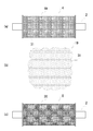
- FIG. 6 (a) shows the details of the X portion of the negative pressure roll shown in FIG.
- Negative pressure conducting grooves 14 are formed on the surface of the inner cylinder 3, and the vent holes 16 of the intermediate cylinder 4 are located at regular intervals. Further, the outer layer 5 of the laminated nonwoven fabric is formed outside the vent hole 16 so that the metal strip 13 and the nonwoven fabric are in contact with each other.
- FIG. 6B is a cross-sectional view of the cross-sectional view (a) in the CC direction.
- FIG. 6B actually has an arc shape, but is shown as a linear diagram for convenience.
- FIG. 7A shows details of the X portion of the negative pressure roll when the intermediate cylinder 4 is formed of the punching metal 19.
- FIG. A negative pressure conduction groove 14 is formed on the surface of the inner cylinder 3, and a punching metal 19 is located on the outer side.
- the multiple nonwoven fabric laminated outer layer 5 is formed outside the punching metal 19 so that the metal strip 13 and the nonwoven fabric are in contact with each other.
- FIG. 7B is a cross-sectional view of the cross-sectional view (a) viewed in the CC direction.
- FIG. 7B actually has an arcuate shape, but is shown as a linear diagram for convenience.
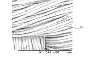
- FIG. 8 shows a photomicrograph (magnification 100 times) of the nonwoven fabric 20 used in the negative pressure roll 1.
- the nonwoven fabric 20 is formed by entwining fibers having a wire diameter of about 4 ⁇ m with high density.
- One nonwoven fabric 20 has a low air permeability of a fragile-type air permeability of about 0.8 cm 3 / cm 2 ⁇ s, and the air permeability of the multiple nonwoven fabric laminated outer layer 5 is extremely low by stacking a plurality of nonwoven fabrics. Can be.
- FIG. 9 shows a photomicrograph of the nonwoven fabric 21 generally used for a tension pad of a tension pad type winding tension applying device.
- the nonwoven fabric 21 is entangled with fibers having a wire diameter of about 20 to 30 ⁇ m, and has a lower density than the nonwoven fabric 20. Further, the single nonwoven fabric 21 has a fragile air permeability of 50 to 100 cm 3 / cm 2 ⁇ s, and is difficult to use as the nonwoven fabric of the multilayer nonwoven fabric laminated outer layer 5.
- the nonwoven fabric 21 is made of a material having a low air permeability of about Frazier air permeability of about 0.8 cm 3 / cm 2 ⁇ s, such as nylon woven cloth.
- the multilayer nonwoven fabric laminated outer layer 5 can be formed by sandwiching the high-density woven fabric 29 between the nonwoven fabrics 21.
- FIG. 10 shows an enlarged micrograph (magnification 100 times) of the high-density woven fabric 29 and
- FIG. 11 shows a general woven fabric 30.
- FIG. 12 is a schematic diagram (a) showing an example of disposing the suction roll device on the slitter line winding side and a schematic diagram (b) showing another example.
- FIG. 13 is a schematic sectional drawing (a) of the suction roll apparatus which has a 90-degree negative pressure area
- the negative pressure roll 1 which is an example of the suction roll apparatus to which the present invention is applied is arranged in the process of the slitter line 22 as shown in FIG. As an example of the arrangement position of the negative pressure roll 1, in FIG. 12A, the negative pressure roll 1 is arranged between the separators 23 and 23 that provide a space between the metal strips.
- a wide metal plate coil is pulled out from an uncoiler (not shown), cut to a desired width by a slitter (not shown), and then a separator 23 that provides a space between multiple strips of metal strip 13. To be granted.
- the metal strip 13 is wound up by the recoiler 24.
- the metal strip 13 that has passed through the separator 23 comes into contact with the multiple nonwoven fabric laminated outer layer 5 of the negative pressure roll 1 from below. At this time, the negative pressure roll 1 rotates in such a manner that it is frictionally engaged at the contact surface between the multiple nonwoven fabric laminated outer layer 5 and the metal strip 13 and pulled by the frictional force.
- the negative pressure roll 1 is sucked in air by a vacuum pump, and the negative pressure conduction portion 10, the negative pressure conduction hole 8, the negative pressure conduction groove 14, the vent hole 16 of the intermediate cylinder 4, and the A negative pressure is formed in the outer layer 5 of the laminated nonwoven fabric.
- the magnitude of the negative pressure can be adjusted by the negative pressure adjusting valve 11.
- the surface side of the metal strip 13 in contact with the negative pressure roll 1 receives a pressure from atmospheric pressure in proportion to the negative pressure generated inside the negative pressure roll 1. Further, the braking device 6 provided on the negative pressure roll 1 can apply a braking force to the rotation. As a result, a winding tension acting in the direction opposite to the direction pulled by the recoiler 24 is applied to the metal strip 13.
- This winding tension applies a tension when the metal strip 13 is wound around the recoiler 24, so that it can be wound up neatly. Moreover, since the nonwoven fabric 20 of the multiple nonwoven fabric laminated outer layer 5 in contact with the metal strip 13 has moderate elasticity, even if a frictional force is generated, the contact surface with the metal strip 13 is hardly damaged. ing.
- the metal strip 13 that has passed through the negative pressure roll 1 is angled by the deflector roll 26 and wound by the recoiler 24, whereby the coil-shaped material of the metal strip 13 is completed.
- the negative pressure roll 1 is used in combination with the belt-type tension device 25 for a thick metal strip that requires a large winding tension. You can also. Alternatively, for materials where slight scratches on the surface are not a problem, they are arranged on the rolls (102 and 103) in FIG. Can also be given.
- the negative pressure roll 1 composed of a low air-permeable surface material does not inhale excess air, so the internal negative pressure is kept high. Even if there is a gap, a sufficient winding tension can be applied.
- a wide sheet-like material formed of paper, resin, or the like can be reliably held and conveyed by being attracted to the negative pressure roll 1.
- a sheet-like material such as paper does not need to be adsorbed with a large negative pressure unlike a metal strip, and can be used with a negative pressure reduced by the negative pressure adjusting valve 11.
- the negative pressure roll 1 composed of a low-breathing surface layer material does not inhale excess air, so there is no need for a partition plate for adjusting the negative pressure area in the roll longitudinal direction even if the material width of the sheet material changes. Therefore, a sufficient gripping force can be exhibited with a simple configuration.
- the braking force with the braking device 6 it is possible to adjust the winding tension and generate extremely low tension.
- extremely low tension can be imparted even to an ultrathin plate having a thickness of about several ⁇ m, such as a metal foil.
- the ultrathin plate is adsorbed by the negative pressure of the negative pressure roll 1, slip does not occur between the negative pressure roll and the ultrathin plate, and sufficient winding tension can be applied.
- the conventional multi-belt belt type winding tension applying device when tension is applied to an ultrathin plate, a mark due to the belt edge adheres to the strip and a slip is generated between the strip and the winding. The take-up tension could not be applied.
- the conventional tension pad method has a problem that scratches adhere to the band plate.
- the winding tension can be increased by increasing the roll diameter of the negative pressure roll 1. That is, a winding tension can be sufficiently applied even to a metal strip having a large plate thickness, and the application range can be expanded.
- the negative pressure conduction portion 10 is formed in a region of approximately 90 degrees on the circumference of the negative pressure roll 1 as shown in FIG.
- the negative pressure roll 1 can be provided at a position where the metal strip 13 rises from below, and can be easily placed on an existing slitter line. The same applies to the transfer line.
- the negative pressure conducting portion 10 can be formed in a region of about 180 degrees on the circumference of the negative pressure roll 1. In this case, since the metal strip 13 rising from below is in contact with the region of about 180 degrees on the negative pressure roll 1, a larger negative pressure can be applied. That is, it is possible to apply a larger winding tension or gripping force. Moreover, if the negative pressure conducting part 10 is prepared as a replacement part having an arbitrary angle, the circumferential negative pressure region can be arbitrarily adjusted.
- the suction roll device to which the present invention is applied can cope with problems peculiar to the multi-strip metal strip. This problem is a problem of a speed difference generated between the metal strips.
- the uncut metal plate coil provided to the slitter line has plate thickness deviations different in thickness in the plate width direction even if the plate is coplanar due to a problem during processing. This thickness deviation leads to an outer diameter difference of the winding coil when the metal strip is wound around the recoiler after being cut into multiple strips.
- the metal strip of the coil having a large outer diameter will be wound faster, and the metal strips due to the outer diameter difference on the negative pressure roll will be wound. A minute speed difference occurs. At this time, the negative pressure roll is drawn and rotated by the metal strip having a large outer diameter, and the winding roll of the metal strip having the small outer diameter is bent and cannot be wound firmly.
- the braking force is increased by the braking device 6 and the rotational speed of the negative pressure roll 1 is suppressed, so that the metal strip having a high winding speed is slightly slipped on the negative pressure roll, and the metal that has been bent is generated. Winding tension can also be applied to the strip.
- the metal strip having a large outer diameter of the winding coil can be easily slipped on the negative pressure roll without increasing the braking force. While slipping a metal strip having a high winding speed, an appropriate winding tension can be applied to a strip having a low winding speed, and a uniform winding tension can be applied to all the metal strips.
- the suction roll device to which the present invention is applied can cope with the problem of the speed difference generated between the multiple strips of metal strips, and can apply a uniform winding tension without scratching. It has become.
- the suction roll device of the present invention can provide a sufficient winding tension by increasing the negative pressure inside the device without damaging the metal strip.
- the winding tension can be applied to a strip having a small thickness or a strip having a small width. Further, it is possible to grip and convey a sheet-like material formed of paper, resin, or the like. Furthermore, uniform winding tension can be imparted to a multi-strand metal strip.
- the suction roll device can sufficiently grasp and convey or brake various long materials without damaging them, and can reliably take up.
Landscapes
- Advancing Webs (AREA)
- Registering, Tensioning, Guiding Webs, And Rollers Therefor (AREA)
- Rolls And Other Rotary Bodies (AREA)
Abstract
Description
図1は、本発明を適用したサクションロール装置の一例を示す概略図である。図2は、図1に示した概略図のA-A断面図(a)及びB-B断面図(b)である。図3は、サクションロール装置の他の一例の負圧導通部に対応する位置の概略断面図(a)及びサクションロール装置の更に別の例の負圧導通部に対応する位置の概略断面図(b)である。図4は、内筒を示す概略図(a)、中間筒を示す概略図(b)及び通気孔の周辺に設ける通気孔溝部を示した概略図(c)である。図5は、パンチングメタルを用いた中間筒を示す概略図(a)、パンチングメタルの小径多数孔を示した概略図(b)及び多重不織布積層外筒を示す概略図(c)である。図6は、図1のX部分の詳細を示す断面図(a)及び断面図(a)のC-C断面図(b)である。図7は、サクションロール装置の他の一例の図6(a)に対応する断面図(a)及び図6(b)に対応する断面図(b)である。図8は、本発明を適用したサクションロール装置に用いた不織布の拡大顕微鏡写真を示す図である。図9は、一般的な不織布の拡大顕微鏡写真を示す図である。図10は、高密度織布の拡大顕微鏡写真を示す図である。図11は、一般的な織布の拡大顕微鏡写真を示す図である。
図12は、サクションロール装置をスリッタ-ライン巻取り側に配置する一例を示す概略図(a)及び他の一例を示す概略図(b)である。図13は、ロール円周上に90度の負圧領域を有するサクションロール装置の概略断面図(a)及び180度の負圧領域を有するサクションロール装置の概略断面図(b)である。
2 回転軸
3 内筒
4 中間筒
5 多重不織布積層外層
6 制動装置
7 軸受部
8 負圧導通孔
9 補強円盤
10 負圧導通部
11 負圧調整弁
12 負圧計
13 金属帯板
14 負圧導通溝
15 仕切り突起
16 通気孔
17 通気孔溝部(四方向)
18 通気孔溝部(八方向)
19 パンチングメタル
20 低通気性の不織布
21 不織布
22 スリッターライン
23 セパレータ
24 リコイラ
25 ベルト式テンション方式の装置
26 デフレクターロール
27 電動機
28 脱着継ぎ手
29 高密度織布
30 一般的な織布
31 パンチングメタルの小径孔
32 回転体本体
矢印Z 負圧ロールの吸引方向
Claims (10)
- 回転可能に構成された回転体本体と、該回転体本体の内部に設けられると共に所定の吸引装置により負圧が形成される導通孔と、前記回転体本体の表面に形成されると共に前記導通孔と接続された導通溝とを有する回転体と、
前記回転体本体の回転を抑止する制動部と、
全ての前記導通溝の外側に設けられ弾性を有すると共に、所定の値以上の摩擦係数を有する低通気性の外層部とを備える
サクションロール装置。 - 回転可能に構成された回転体本体と、該回転体本体の内部に設けられると共に所定の吸引装置により負圧が形成される導通孔と、前記回転体本体の表面に形成されると共に前記導通孔と接続された導通溝とを有する回転体と、
前記回転体本体を回転させる駆動部と、
全ての前記導通溝の外側に設けられ弾性を有すると共に、所定の値以上の摩擦係数を有する低通気性の外層部とを備える
サクションロール装置。 - 前記回転体本体を回転させる駆動部と、
該駆動部と前記回転体本体を脱着するクラッチとを備える
請求項1に記載のサクションロール装置。 - 前記回転体は前記導通孔を流れる空気の量を調節可能に構成された
請求項1、請求項2または請求項3に記載のサクションロール装置。 - 前記導通溝と前記外層部との間に設けられると共に複数の通気孔が形成された略円筒状の中間筒部を備える
請求項1、請求項2または請求項3に記載のサクションロール装置。 - 前記中間筒部は前記通気孔を中心に半径方向に形成された少なくとも1本の通気孔溝部を有する
請求項5に記載のサクションロール装置。 - 前記回転体本体は略円筒状に形成され、
前記導通孔は前記回転体本体の円周方向に複数形成されると共に、隣接した前記導通孔同士が一定間隔を有し、
前記導通溝は前記回転体本体の長手方向に複数形成されると共に、隣接した前記導通溝同士が一定間隔を有する
請求項1、請求項2または請求項3に記載のサクションロール装置。 - 前記回転体は、前記導通孔の総断面積と前記導通溝の総断面積が略等しく形成された
請求項1、請求項2または請求項3に記載のサクションロール装置。 - 前記外層部は低通気性の不織布で形成された
請求項1、請求項2または請求項3に記載のサクションロール装置。 - 前記外層部の通気度がフラジール形通気度で0.2cm3/cm2・s以下である
請求項1、請求項2または請求項3に記載のサクションロール装置。
Priority Applications (9)
| Application Number | Priority Date | Filing Date | Title |
|---|---|---|---|
| CN201380028712.8A CN105008259B (zh) | 2013-02-06 | 2013-02-06 | 吸辊装置 |
| KR1020147033570A KR101589552B1 (ko) | 2013-02-06 | 2013-02-06 | 흡입 롤 장치 |
| EP13874273.9A EP2955136B1 (en) | 2013-02-06 | 2013-02-06 | Suction roll device |
| JP2013553685A JP5565889B1 (ja) | 2013-02-06 | 2013-02-06 | サクションロール装置 |
| US14/403,342 US9663315B2 (en) | 2013-02-06 | 2013-02-06 | Suction roll device |
| HK16103892.5A HK1215941B (en) | 2013-02-06 | Suction roll device | |
| ES13874273T ES2753873T3 (es) | 2013-02-06 | 2013-02-06 | Dispositivo de rodillo de succión |
| PCT/JP2013/052742 WO2014122737A1 (ja) | 2013-02-06 | 2013-02-06 | サクションロール装置 |
| TW103102759A TWI480218B (zh) | 2013-02-06 | 2014-01-24 | Suction roller device |
Applications Claiming Priority (1)
| Application Number | Priority Date | Filing Date | Title |
|---|---|---|---|
| PCT/JP2013/052742 WO2014122737A1 (ja) | 2013-02-06 | 2013-02-06 | サクションロール装置 |
Publications (1)
| Publication Number | Publication Date |
|---|---|
| WO2014122737A1 true WO2014122737A1 (ja) | 2014-08-14 |
Family
ID=51299351
Family Applications (1)
| Application Number | Title | Priority Date | Filing Date |
|---|---|---|---|
| PCT/JP2013/052742 Ceased WO2014122737A1 (ja) | 2013-02-06 | 2013-02-06 | サクションロール装置 |
Country Status (8)
| Country | Link |
|---|---|
| US (1) | US9663315B2 (ja) |
| EP (1) | EP2955136B1 (ja) |
| JP (1) | JP5565889B1 (ja) |
| KR (1) | KR101589552B1 (ja) |
| CN (1) | CN105008259B (ja) |
| ES (1) | ES2753873T3 (ja) |
| TW (1) | TWI480218B (ja) |
| WO (1) | WO2014122737A1 (ja) |
Families Citing this family (26)
| Publication number | Priority date | Publication date | Assignee | Title |
|---|---|---|---|---|
| US20120157279A1 (en) * | 2010-12-20 | 2012-06-21 | Uwe Schneider | Process and Apparatus for Joining Flexible Components |
| JP5652800B1 (ja) * | 2014-02-03 | 2015-01-14 | Jdc株式会社 | スリッターラインのループ量吸収装置 |
| WO2015132961A1 (ja) * | 2014-03-07 | 2015-09-11 | Jdc株式会社 | 負圧シート構造 |
| CN105173861A (zh) * | 2015-09-11 | 2015-12-23 | 苏州爱可姆机械有限公司 | 一种真空吸附辊装置 |
| CN105398855A (zh) * | 2015-12-15 | 2016-03-16 | 无锡宝南机器制造有限公司 | 数码书刊折页机牵引辊面局部吸附结构 |
| CN105417260B (zh) * | 2015-12-15 | 2017-11-07 | 无锡宝南机器制造有限公司 | 数码书刊折页机牵引辊面气量调节机构 |
| DE102018000819B4 (de) | 2017-02-01 | 2024-05-29 | Danieli Germany GmbH | Vakuumbremsrollenanlage und Betriebsverfahren dafür sowie Längsteilanlage damit |
| CN107537741A (zh) * | 2017-10-23 | 2018-01-05 | 无锡唯勒科技有限公司 | 新型隔膜张力控制辊 |
| CN107814228A (zh) * | 2017-11-24 | 2018-03-20 | 佛山市南海区德昌誉机械制造有限公司 | 一种轴向负压控制的吸附辊 |
| CN109368317A (zh) * | 2018-10-08 | 2019-02-22 | 深圳市哈德胜精密科技股份有限公司 | 负压吸附传送装置 |
| KR102178679B1 (ko) * | 2018-12-19 | 2020-11-13 | 주식회사 포스코 | 이물질 제거형 강판 이송롤 |
| CN109399312A (zh) * | 2018-12-25 | 2019-03-01 | 美塞斯(珠海)工业自动化设备有限公司 | 一种真空辊 |
| KR102438087B1 (ko) * | 2020-06-23 | 2022-08-31 | 주식회사 창명산업 | 공기흡입유닛이 적용된 원통회전형 전기방사장치 |
| KR102466824B1 (ko) * | 2020-11-04 | 2022-11-15 | 주식회사제이에스텍 | 석션폭 가변형 석션롤 |
| CN112301356B (zh) * | 2020-11-10 | 2023-03-03 | 安徽众源新材料股份有限公司 | 一种铜带箔脱脂清洗线 |
| CN112899411B (zh) * | 2021-01-22 | 2022-06-10 | 南通大学 | 一种基于皮革自动铺平装置的皮革自动铺平方法 |
| US11851298B2 (en) * | 2021-05-28 | 2023-12-26 | Renova S.R.L. | Machine for producing cardboard |
| CN113257157B (zh) * | 2021-06-18 | 2021-11-05 | 潍坊科技学院 | 一种智能宣传栏 |
| CN113684661B (zh) * | 2021-08-29 | 2022-12-23 | 江西艾酷玩具有限公司 | 纺织用环保去绒机 |
| CN113788350A (zh) * | 2021-09-24 | 2021-12-14 | 绍兴市柯桥区伟峰纺织品有限公司 | 弹性布料传送装置 |
| CN113968019B (zh) * | 2021-11-23 | 2024-04-26 | 福州恒美光电材料有限公司 | 聚酰亚胺薄膜生产用膜材拉伸设备及其拉伸方法 |
| CN116331919B (zh) * | 2021-12-22 | 2025-07-11 | 奥美医疗用品股份有限公司 | 避免负压空气互通的转鼓结构及方法 |
| CN117401475B (zh) * | 2023-12-14 | 2024-04-19 | 东莞市万豪包装有限公司 | 一种包装袋彩印自动传送装置 |
| CN117923224B (zh) * | 2023-12-22 | 2024-08-16 | 格锐特(肇庆)机械设备有限公司 | 一种应用于碳纸涂布系统的无压辊式张力阻断装置 |
| CN117732892B (zh) * | 2023-12-22 | 2025-06-24 | 无锡腾达海川新材料有限公司 | 一种电池镍带加工用冷轧设备及冷轧方法 |
| KR102705243B1 (ko) | 2023-12-22 | 2024-09-11 | 배규상 | 시트 흡착용 석션롤러 |
Citations (12)
| Publication number | Priority date | Publication date | Assignee | Title |
|---|---|---|---|---|
| JPS63267648A (ja) * | 1987-04-24 | 1988-11-04 | Teijin Ltd | フイルム搬送装置 |
| JPS63299816A (ja) * | 1987-05-30 | 1988-12-07 | Nippon Kaihatsu Consultant:Kk | テンションロ−ル装置及びブレ−キ付テンションロ−ル装置 |
| JPH05253615A (ja) | 1992-11-02 | 1993-10-05 | Sannou Tekko Kk | バックテンション付与用弾性ロール |
| JPH06238329A (ja) | 1992-12-08 | 1994-08-30 | Sannou Tekko Kk | 金属帯板の張力付与装置 |
| JPH07127631A (ja) | 1993-11-05 | 1995-05-16 | Berumateitsuku:Kk | 吸気幅可変型サクションローラ |
| JPH09175700A (ja) * | 1995-12-28 | 1997-07-08 | Unitika Ltd | フィルム供給装置 |
| JP2000108299A (ja) * | 1998-10-01 | 2000-04-18 | Heidelberger Druckmas Ag | 枚葉紙輪転印刷機用の印刷胴 |
| JP2004142936A (ja) * | 2002-08-30 | 2004-05-20 | Toshiba Mach Co Ltd | サクションロール装置 |
| JP2004230449A (ja) | 2003-01-31 | 2004-08-19 | Nippon Kaihatsu Consultant:Kk | 帯板巻取り張力付与装置 |
| JP2005262310A (ja) | 2004-03-22 | 2005-09-29 | Nisshin Steel Co Ltd | 金属帯の裁断装置 |
| JP2008137804A (ja) | 2006-12-05 | 2008-06-19 | Himecs:Kk | サクションロール装置 |
| JP2012081477A (ja) | 2010-10-07 | 2012-04-26 | Nippon Kaihatsu Consultant:Kk | 多条エンドレスベルト式帯板巻取り張力付与装置 |
Family Cites Families (11)
| Publication number | Priority date | Publication date | Assignee | Title |
|---|---|---|---|---|
| US4011975A (en) * | 1975-09-08 | 1977-03-15 | Packaging Industries, Inc. | Web handling system |
| US4437369A (en) * | 1982-07-19 | 1984-03-20 | Opelika Manufacturing Corporation | Sheet material cutting method and apparatus |
| IT1317956B1 (it) * | 2000-05-31 | 2003-07-21 | Fimi Spa | Rullo di frenatura per impianti di taglio di nastri metallici instrisce. |
| JP2003312909A (ja) * | 2002-04-22 | 2003-11-06 | Hikoyama Seiki Kk | 自己吸引式サクションロール及びこのサクションロールを用いたフィルム状基材の搬送装置 |
| US8640862B2 (en) * | 2006-04-10 | 2014-02-04 | Albany International Corp. | Seam-on laminated belt |
| ITMI20071133A1 (it) * | 2007-06-04 | 2008-12-05 | No El Srl | Metodo e apparecchiatura per la corrugazione e 'avvolgimento di bobine di film plastico |
| WO2009028564A1 (ja) * | 2007-08-31 | 2009-03-05 | Kuraray Kuraflex Co., Ltd. | 緩衝材用基材及びその用途 |
| JP2011207579A (ja) * | 2010-03-30 | 2011-10-20 | Jx Nippon Mining & Metals Corp | 被覆ロール及びそれを用いた帯状体の搬送装置 |
| JP5838024B2 (ja) * | 2010-08-30 | 2015-12-24 | ユニ・チャーム株式会社 | 吸収性物品に係る連続シートの複合体の製造方法、製造装置、及び吸収性物品の製造方法 |
| CN201801214U (zh) * | 2010-09-21 | 2011-04-20 | 台湾恒基股份有限公司 | 软板的吸附传输装置 |
| US8931675B2 (en) * | 2012-02-08 | 2015-01-13 | Carpe Diem Technologies, Inc. | Web handling system and vacuum roller for use in conjunction therewith |
-
2013
- 2013-02-06 JP JP2013553685A patent/JP5565889B1/ja active Active
- 2013-02-06 ES ES13874273T patent/ES2753873T3/es active Active
- 2013-02-06 CN CN201380028712.8A patent/CN105008259B/zh active Active
- 2013-02-06 KR KR1020147033570A patent/KR101589552B1/ko active Active
- 2013-02-06 EP EP13874273.9A patent/EP2955136B1/en active Active
- 2013-02-06 US US14/403,342 patent/US9663315B2/en active Active
- 2013-02-06 WO PCT/JP2013/052742 patent/WO2014122737A1/ja not_active Ceased
-
2014
- 2014-01-24 TW TW103102759A patent/TWI480218B/zh active
Patent Citations (12)
| Publication number | Priority date | Publication date | Assignee | Title |
|---|---|---|---|---|
| JPS63267648A (ja) * | 1987-04-24 | 1988-11-04 | Teijin Ltd | フイルム搬送装置 |
| JPS63299816A (ja) * | 1987-05-30 | 1988-12-07 | Nippon Kaihatsu Consultant:Kk | テンションロ−ル装置及びブレ−キ付テンションロ−ル装置 |
| JPH05253615A (ja) | 1992-11-02 | 1993-10-05 | Sannou Tekko Kk | バックテンション付与用弾性ロール |
| JPH06238329A (ja) | 1992-12-08 | 1994-08-30 | Sannou Tekko Kk | 金属帯板の張力付与装置 |
| JPH07127631A (ja) | 1993-11-05 | 1995-05-16 | Berumateitsuku:Kk | 吸気幅可変型サクションローラ |
| JPH09175700A (ja) * | 1995-12-28 | 1997-07-08 | Unitika Ltd | フィルム供給装置 |
| JP2000108299A (ja) * | 1998-10-01 | 2000-04-18 | Heidelberger Druckmas Ag | 枚葉紙輪転印刷機用の印刷胴 |
| JP2004142936A (ja) * | 2002-08-30 | 2004-05-20 | Toshiba Mach Co Ltd | サクションロール装置 |
| JP2004230449A (ja) | 2003-01-31 | 2004-08-19 | Nippon Kaihatsu Consultant:Kk | 帯板巻取り張力付与装置 |
| JP2005262310A (ja) | 2004-03-22 | 2005-09-29 | Nisshin Steel Co Ltd | 金属帯の裁断装置 |
| JP2008137804A (ja) | 2006-12-05 | 2008-06-19 | Himecs:Kk | サクションロール装置 |
| JP2012081477A (ja) | 2010-10-07 | 2012-04-26 | Nippon Kaihatsu Consultant:Kk | 多条エンドレスベルト式帯板巻取り張力付与装置 |
Also Published As
| Publication number | Publication date |
|---|---|
| US9663315B2 (en) | 2017-05-30 |
| EP2955136B1 (en) | 2019-09-25 |
| JPWO2014122737A1 (ja) | 2017-01-26 |
| KR101589552B1 (ko) | 2016-01-28 |
| EP2955136A1 (en) | 2015-12-16 |
| TWI480218B (zh) | 2015-04-11 |
| ES2753873T3 (es) | 2020-04-14 |
| TW201446630A (zh) | 2014-12-16 |
| JP5565889B1 (ja) | 2014-08-06 |
| US20150102153A1 (en) | 2015-04-16 |
| KR20150006032A (ko) | 2015-01-15 |
| CN105008259B (zh) | 2016-09-14 |
| HK1215941A1 (zh) | 2016-09-30 |
| CN105008259A (zh) | 2015-10-28 |
| EP2955136A4 (en) | 2017-10-04 |
Similar Documents
| Publication | Publication Date | Title |
|---|---|---|
| JP5565889B1 (ja) | サクションロール装置 | |
| JP5393394B2 (ja) | 吸収性物品に係る連続シートの複合体の製造方法、及び製造装置 | |
| WO2010001882A1 (ja) | 間欠切断転写装置 | |
| CN110556508B (zh) | 极片加工设备 | |
| TW201527839A (zh) | 壓合光學膜之系統及利用其製造顯示單元之方法 | |
| KR101017122B1 (ko) | 곡면용 필름부착 장치 및 이를 이용한 필름부착 방법 | |
| WO2015114837A1 (ja) | スリッターラインのループ量吸収装置 | |
| CN106170359B (zh) | 对金属带板产生负压的构造体 | |
| JP6551237B2 (ja) | 溝付ローラー、ならびにこれを用いたプラスチックフィルムの製造装置および製造方法 | |
| JP3707341B2 (ja) | 電池用電極の製造方法及び製造装置 | |
| JP2014101221A (ja) | 帯状体の搬送装置 | |
| WO2014006902A1 (en) | Method for manufacturing a composite body of continuous sheets for an absorbent article and apparatus of the same | |
| HK1215941B (en) | Suction roll device | |
| JP3897040B2 (ja) | 積層板製造用の金属箔と絶縁接着フィルムの積み重ね装置及び積み重ね方法 | |
| CN215969089U (zh) | 一种落料组件及具有其的过滤棉裁切机 | |
| JP6589682B2 (ja) | シート搬送装置 | |
| KR101946965B1 (ko) | 포장용 필름 합지장치의 가이드롤러장치 | |
| JP2016113285A (ja) | サクションロール、ウェブの搬送装置およびウェブの搬送方法 | |
| JPH01150414A (ja) | ストリップ条帯の巻取装置 | |
| JP2018203464A (ja) | ガラスチョップドストランドマットの巻回体の製造方法およびガラスチョップドストランドマットの巻回体 |
Legal Events
| Date | Code | Title | Description |
|---|---|---|---|
| ENP | Entry into the national phase |
Ref document number: 2013553685 Country of ref document: JP Kind code of ref document: A |
|
| 121 | Ep: the epo has been informed by wipo that ep was designated in this application |
Ref document number: 13874273 Country of ref document: EP Kind code of ref document: A1 |
|
| WWE | Wipo information: entry into national phase |
Ref document number: 2013874273 Country of ref document: EP |
|
| WWE | Wipo information: entry into national phase |
Ref document number: 14403342 Country of ref document: US |
|
| ENP | Entry into the national phase |
Ref document number: 20147033570 Country of ref document: KR Kind code of ref document: A |
|
| NENP | Non-entry into the national phase |
Ref country code: DE |