WO2014125841A1 - 方向性電磁鋼板の窒化処理設備および窒化処理方法 - Google Patents
方向性電磁鋼板の窒化処理設備および窒化処理方法 Download PDFInfo
- Publication number
- WO2014125841A1 WO2014125841A1 PCT/JP2014/000820 JP2014000820W WO2014125841A1 WO 2014125841 A1 WO2014125841 A1 WO 2014125841A1 JP 2014000820 W JP2014000820 W JP 2014000820W WO 2014125841 A1 WO2014125841 A1 WO 2014125841A1
- Authority
- WO
- WIPO (PCT)
- Prior art keywords
- nitriding
- zone
- equipment
- grain
- electrical steel
- Prior art date
- Legal status (The legal status is an assumption and is not a legal conclusion. Google has not performed a legal analysis and makes no representation as to the accuracy of the status listed.)
- Ceased
Links
Images


Classifications
-
- C—CHEMISTRY; METALLURGY
- C23—COATING METALLIC MATERIAL; COATING MATERIAL WITH METALLIC MATERIAL; CHEMICAL SURFACE TREATMENT; DIFFUSION TREATMENT OF METALLIC MATERIAL; COATING BY VACUUM EVAPORATION, BY SPUTTERING, BY ION IMPLANTATION OR BY CHEMICAL VAPOUR DEPOSITION, IN GENERAL; INHIBITING CORROSION OF METALLIC MATERIAL OR INCRUSTATION IN GENERAL
- C23C—COATING METALLIC MATERIAL; COATING MATERIAL WITH METALLIC MATERIAL; SURFACE TREATMENT OF METALLIC MATERIAL BY DIFFUSION INTO THE SURFACE, BY CHEMICAL CONVERSION OR SUBSTITUTION; COATING BY VACUUM EVAPORATION, BY SPUTTERING, BY ION IMPLANTATION OR BY CHEMICAL VAPOUR DEPOSITION, IN GENERAL
- C23C8/00—Solid state diffusion of only non-metal elements into metallic material surfaces; Chemical surface treatment of metallic material by reaction of the surface with a reactive gas, leaving reaction products of surface material in the coating, e.g. conversion coatings, passivation of metals
- C23C8/06—Solid state diffusion of only non-metal elements into metallic material surfaces; Chemical surface treatment of metallic material by reaction of the surface with a reactive gas, leaving reaction products of surface material in the coating, e.g. conversion coatings, passivation of metals using gases
- C23C8/36—Solid state diffusion of only non-metal elements into metallic material surfaces; Chemical surface treatment of metallic material by reaction of the surface with a reactive gas, leaving reaction products of surface material in the coating, e.g. conversion coatings, passivation of metals using gases using ionised gases, e.g. ionitriding
- C23C8/38—Treatment of ferrous surfaces
-
- C—CHEMISTRY; METALLURGY
- C21—METALLURGY OF IRON
- C21D—MODIFYING THE PHYSICAL STRUCTURE OF FERROUS METALS; GENERAL DEVICES FOR HEAT TREATMENT OF FERROUS OR NON-FERROUS METALS OR ALLOYS; MAKING METAL MALLEABLE, e.g. BY DECARBURISATION OR TEMPERING
- C21D8/00—Modifying the physical properties of ferrous metals or ferrous alloys by deformation combined with, or followed by, heat treatment
- C21D8/12—Modifying the physical properties of ferrous metals or ferrous alloys by deformation combined with, or followed by, heat treatment during manufacturing of articles with special electromagnetic properties
- C21D8/1244—Modifying the physical properties of ferrous metals or ferrous alloys by deformation combined with, or followed by, heat treatment during manufacturing of articles with special electromagnetic properties characterised by the heat treatment
- C21D8/1255—Modifying the physical properties of ferrous metals or ferrous alloys by deformation combined with, or followed by, heat treatment during manufacturing of articles with special electromagnetic properties characterised by the heat treatment with diffusion of elements, e.g. decarburising, nitriding
-
- C—CHEMISTRY; METALLURGY
- C21—METALLURGY OF IRON
- C21D—MODIFYING THE PHYSICAL STRUCTURE OF FERROUS METALS; GENERAL DEVICES FOR HEAT TREATMENT OF FERROUS OR NON-FERROUS METALS OR ALLOYS; MAKING METAL MALLEABLE, e.g. BY DECARBURISATION OR TEMPERING
- C21D9/00—Heat treatment, e.g. annealing, hardening, quenching or tempering, adapted for particular articles; Furnaces therefor
- C21D9/46—Heat treatment, e.g. annealing, hardening, quenching or tempering, adapted for particular articles; Furnaces therefor for sheet metals
-
- C—CHEMISTRY; METALLURGY
- C22—METALLURGY; FERROUS OR NON-FERROUS ALLOYS; TREATMENT OF ALLOYS OR NON-FERROUS METALS
- C22C—ALLOYS
- C22C38/00—Ferrous alloys, e.g. steel alloys
- C22C38/02—Ferrous alloys, e.g. steel alloys containing silicon
-
- C—CHEMISTRY; METALLURGY
- C23—COATING METALLIC MATERIAL; COATING MATERIAL WITH METALLIC MATERIAL; CHEMICAL SURFACE TREATMENT; DIFFUSION TREATMENT OF METALLIC MATERIAL; COATING BY VACUUM EVAPORATION, BY SPUTTERING, BY ION IMPLANTATION OR BY CHEMICAL VAPOUR DEPOSITION, IN GENERAL; INHIBITING CORROSION OF METALLIC MATERIAL OR INCRUSTATION IN GENERAL
- C23C—COATING METALLIC MATERIAL; COATING MATERIAL WITH METALLIC MATERIAL; SURFACE TREATMENT OF METALLIC MATERIAL BY DIFFUSION INTO THE SURFACE, BY CHEMICAL CONVERSION OR SUBSTITUTION; COATING BY VACUUM EVAPORATION, BY SPUTTERING, BY ION IMPLANTATION OR BY CHEMICAL VAPOUR DEPOSITION, IN GENERAL
- C23C8/00—Solid state diffusion of only non-metal elements into metallic material surfaces; Chemical surface treatment of metallic material by reaction of the surface with a reactive gas, leaving reaction products of surface material in the coating, e.g. conversion coatings, passivation of metals
- C23C8/02—Pretreatment of the material to be coated
-
- C—CHEMISTRY; METALLURGY
- C23—COATING METALLIC MATERIAL; COATING MATERIAL WITH METALLIC MATERIAL; CHEMICAL SURFACE TREATMENT; DIFFUSION TREATMENT OF METALLIC MATERIAL; COATING BY VACUUM EVAPORATION, BY SPUTTERING, BY ION IMPLANTATION OR BY CHEMICAL VAPOUR DEPOSITION, IN GENERAL; INHIBITING CORROSION OF METALLIC MATERIAL OR INCRUSTATION IN GENERAL
- C23C—COATING METALLIC MATERIAL; COATING MATERIAL WITH METALLIC MATERIAL; SURFACE TREATMENT OF METALLIC MATERIAL BY DIFFUSION INTO THE SURFACE, BY CHEMICAL CONVERSION OR SUBSTITUTION; COATING BY VACUUM EVAPORATION, BY SPUTTERING, BY ION IMPLANTATION OR BY CHEMICAL VAPOUR DEPOSITION, IN GENERAL
- C23C8/00—Solid state diffusion of only non-metal elements into metallic material surfaces; Chemical surface treatment of metallic material by reaction of the surface with a reactive gas, leaving reaction products of surface material in the coating, e.g. conversion coatings, passivation of metals
- C23C8/06—Solid state diffusion of only non-metal elements into metallic material surfaces; Chemical surface treatment of metallic material by reaction of the surface with a reactive gas, leaving reaction products of surface material in the coating, e.g. conversion coatings, passivation of metals using gases
- C23C8/08—Solid state diffusion of only non-metal elements into metallic material surfaces; Chemical surface treatment of metallic material by reaction of the surface with a reactive gas, leaving reaction products of surface material in the coating, e.g. conversion coatings, passivation of metals using gases only one element being applied
- C23C8/24—Nitriding
- C23C8/26—Nitriding of ferrous surfaces
-
- H—ELECTRICITY
- H01—ELECTRIC ELEMENTS
- H01F—MAGNETS; INDUCTANCES; TRANSFORMERS; SELECTION OF MATERIALS FOR THEIR MAGNETIC PROPERTIES
- H01F1/00—Magnets or magnetic bodies characterised by the magnetic materials therefor; Selection of materials for their magnetic properties
- H01F1/01—Magnets or magnetic bodies characterised by the magnetic materials therefor; Selection of materials for their magnetic properties of inorganic materials
- H01F1/03—Magnets or magnetic bodies characterised by the magnetic materials therefor; Selection of materials for their magnetic properties of inorganic materials characterised by their coercivity
- H01F1/12—Magnets or magnetic bodies characterised by the magnetic materials therefor; Selection of materials for their magnetic properties of inorganic materials characterised by their coercivity of soft-magnetic materials
- H01F1/14—Magnets or magnetic bodies characterised by the magnetic materials therefor; Selection of materials for their magnetic properties of inorganic materials characterised by their coercivity of soft-magnetic materials metals or alloys
- H01F1/147—Alloys characterised by their composition
- H01F1/14766—Fe-Si based alloys
- H01F1/14775—Fe-Si based alloys in the form of sheets
-
- H—ELECTRICITY
- H01—ELECTRIC ELEMENTS
- H01F—MAGNETS; INDUCTANCES; TRANSFORMERS; SELECTION OF MATERIALS FOR THEIR MAGNETIC PROPERTIES
- H01F1/00—Magnets or magnetic bodies characterised by the magnetic materials therefor; Selection of materials for their magnetic properties
- H01F1/01—Magnets or magnetic bodies characterised by the magnetic materials therefor; Selection of materials for their magnetic properties of inorganic materials
- H01F1/03—Magnets or magnetic bodies characterised by the magnetic materials therefor; Selection of materials for their magnetic properties of inorganic materials characterised by their coercivity
- H01F1/12—Magnets or magnetic bodies characterised by the magnetic materials therefor; Selection of materials for their magnetic properties of inorganic materials characterised by their coercivity of soft-magnetic materials
- H01F1/14—Magnets or magnetic bodies characterised by the magnetic materials therefor; Selection of materials for their magnetic properties of inorganic materials characterised by their coercivity of soft-magnetic materials metals or alloys
- H01F1/16—Magnets or magnetic bodies characterised by the magnetic materials therefor; Selection of materials for their magnetic properties of inorganic materials characterised by their coercivity of soft-magnetic materials metals or alloys in the form of sheets
-
- C—CHEMISTRY; METALLURGY
- C21—METALLURGY OF IRON
- C21D—MODIFYING THE PHYSICAL STRUCTURE OF FERROUS METALS; GENERAL DEVICES FOR HEAT TREATMENT OF FERROUS OR NON-FERROUS METALS OR ALLOYS; MAKING METAL MALLEABLE, e.g. BY DECARBURISATION OR TEMPERING
- C21D1/00—General methods or devices for heat treatment, e.g. annealing, hardening, quenching or tempering
- C21D1/06—Surface hardening
- C21D1/09—Surface hardening by direct application of electrical or wave energy; by particle radiation
-
- C—CHEMISTRY; METALLURGY
- C21—METALLURGY OF IRON
- C21D—MODIFYING THE PHYSICAL STRUCTURE OF FERROUS METALS; GENERAL DEVICES FOR HEAT TREATMENT OF FERROUS OR NON-FERROUS METALS OR ALLOYS; MAKING METAL MALLEABLE, e.g. BY DECARBURISATION OR TEMPERING
- C21D1/00—General methods or devices for heat treatment, e.g. annealing, hardening, quenching or tempering
- C21D1/74—Methods of treatment in inert gas, controlled atmosphere, vacuum or pulverulent material
- C21D1/773—Methods of treatment in inert gas, controlled atmosphere, vacuum or pulverulent material under reduced pressure or vacuum
-
- C—CHEMISTRY; METALLURGY
- C21—METALLURGY OF IRON
- C21D—MODIFYING THE PHYSICAL STRUCTURE OF FERROUS METALS; GENERAL DEVICES FOR HEAT TREATMENT OF FERROUS OR NON-FERROUS METALS OR ALLOYS; MAKING METAL MALLEABLE, e.g. BY DECARBURISATION OR TEMPERING
- C21D2201/00—Treatment for obtaining particular effects
- C21D2201/05—Grain orientation
-
- C—CHEMISTRY; METALLURGY
- C23—COATING METALLIC MATERIAL; COATING MATERIAL WITH METALLIC MATERIAL; CHEMICAL SURFACE TREATMENT; DIFFUSION TREATMENT OF METALLIC MATERIAL; COATING BY VACUUM EVAPORATION, BY SPUTTERING, BY ION IMPLANTATION OR BY CHEMICAL VAPOUR DEPOSITION, IN GENERAL; INHIBITING CORROSION OF METALLIC MATERIAL OR INCRUSTATION IN GENERAL
- C23C—COATING METALLIC MATERIAL; COATING MATERIAL WITH METALLIC MATERIAL; SURFACE TREATMENT OF METALLIC MATERIAL BY DIFFUSION INTO THE SURFACE, BY CHEMICAL CONVERSION OR SUBSTITUTION; COATING BY VACUUM EVAPORATION, BY SPUTTERING, BY ION IMPLANTATION OR BY CHEMICAL VAPOUR DEPOSITION, IN GENERAL
- C23C14/00—Coating by vacuum evaporation, by sputtering or by ion implantation of the coating forming material
- C23C14/06—Coating by vacuum evaporation, by sputtering or by ion implantation of the coating forming material characterised by the coating material
-
- C—CHEMISTRY; METALLURGY
- C23—COATING METALLIC MATERIAL; COATING MATERIAL WITH METALLIC MATERIAL; CHEMICAL SURFACE TREATMENT; DIFFUSION TREATMENT OF METALLIC MATERIAL; COATING BY VACUUM EVAPORATION, BY SPUTTERING, BY ION IMPLANTATION OR BY CHEMICAL VAPOUR DEPOSITION, IN GENERAL; INHIBITING CORROSION OF METALLIC MATERIAL OR INCRUSTATION IN GENERAL
- C23C—COATING METALLIC MATERIAL; COATING MATERIAL WITH METALLIC MATERIAL; SURFACE TREATMENT OF METALLIC MATERIAL BY DIFFUSION INTO THE SURFACE, BY CHEMICAL CONVERSION OR SUBSTITUTION; COATING BY VACUUM EVAPORATION, BY SPUTTERING, BY ION IMPLANTATION OR BY CHEMICAL VAPOUR DEPOSITION, IN GENERAL
- C23C14/00—Coating by vacuum evaporation, by sputtering or by ion implantation of the coating forming material
- C23C14/22—Coating by vacuum evaporation, by sputtering or by ion implantation of the coating forming material characterised by the process of coating
- C23C14/24—Vacuum evaporation
-
- C—CHEMISTRY; METALLURGY
- C23—COATING METALLIC MATERIAL; COATING MATERIAL WITH METALLIC MATERIAL; CHEMICAL SURFACE TREATMENT; DIFFUSION TREATMENT OF METALLIC MATERIAL; COATING BY VACUUM EVAPORATION, BY SPUTTERING, BY ION IMPLANTATION OR BY CHEMICAL VAPOUR DEPOSITION, IN GENERAL; INHIBITING CORROSION OF METALLIC MATERIAL OR INCRUSTATION IN GENERAL
- C23C—COATING METALLIC MATERIAL; COATING MATERIAL WITH METALLIC MATERIAL; SURFACE TREATMENT OF METALLIC MATERIAL BY DIFFUSION INTO THE SURFACE, BY CHEMICAL CONVERSION OR SUBSTITUTION; COATING BY VACUUM EVAPORATION, BY SPUTTERING, BY ION IMPLANTATION OR BY CHEMICAL VAPOUR DEPOSITION, IN GENERAL
- C23C14/00—Coating by vacuum evaporation, by sputtering or by ion implantation of the coating forming material
- C23C14/22—Coating by vacuum evaporation, by sputtering or by ion implantation of the coating forming material characterised by the process of coating
- C23C14/56—Apparatus specially adapted for continuous coating; Arrangements for maintaining the vacuum, e.g. vacuum locks
- C23C14/562—Apparatus specially adapted for continuous coating; Arrangements for maintaining the vacuum, e.g. vacuum locks for coating elongated substrates
Definitions
- the present invention relates to a nitriding equipment and a nitriding method for a directional electrical steel sheet suitable for nitriding a directional electrical steel sheet.
- Oriented electrical steel sheet is a soft magnetic material used as an iron core material for transformers and generators, and is required to have excellent magnetization characteristics, particularly low iron loss.
- This steel sheet has a texture in which the ⁇ 001> direction, which is the easy axis of iron, is highly aligned in the rolling direction of the steel sheet.
- Such a texture is preferentially large in the grain of (110) [001] orientation called the Goss orientation during the secondary recrystallization annealing during the manufacturing process of the grain-oriented electrical steel sheet. It is formed through so-called secondary recrystallization.
- such grain-oriented electrical steel sheets were heated to 1300 ° C. or higher by heating a slab containing 4.5 mass% or less of Si and an inhibitor component such as MnS, MnSe, or AlN to temporarily dissolve the inhibitor component.
- the final sheet thickness is obtained by one or more cold rollings sandwiching intermediate annealing, followed by primary recrystallization annealing in a wet hydrogen atmosphere
- an annealing separator mainly composed of magnesia (MgO) the final recrystallization and inhibitor components are purified at 1200 ° C. for about 5 hours. It has been manufactured by performing finish annealing (for example, Patent Document 1, Patent Document 2, and Patent Document 3).
- the high-temperature heating of the slab not only increases the equipment cost for realizing the heating, but also increases the amount of scale generated during hot rolling, thereby reducing the yield and further complicating the maintenance of the equipment. Therefore, there has been a problem that it has not been possible to meet the recent demands for reducing manufacturing costs.
- the inhibitor is strengthened and stabilized after the primary recrystallization annealing and before the completion of the secondary recrystallization even if the inhibitor component is not included in the slab.
- a technique (Patent Document 5) that can cause secondary recrystallization and a technique (Patent Document 6) that installs a reduction zone to give a reduction action to the oxide layer on the steel sheet surface before the nitriding zone are proposed. ing.
- Patent Document 7 a method of adjusting the nitriding gas supplied by a nozzle or spray by dividing the steel plate at the center and both ends of the steel plate has been proposed. 7).
- Patent Document 4 the amount of vulcanization in the coil changes due to temperature and atmosphere unevenness when the coil is heated, resulting in a difference in secondary recrystallization behavior. Variations may occur. Further, since the techniques disclosed in Patent Documents 5 to 7 are methods for nitriding by spraying a nitriding gas onto a steel sheet, nitriding in a pipe due to temporal and positional non-uniformity in the furnace temperature or heat. Depending on the amount of decomposition of the reactive gas, the amount of increase in nitriding may differ depending on the portion of the strip, resulting in non-uniform secondary recrystallization and deterioration of magnetic properties.
- the present invention was developed in view of the above situation, and in the production of grain-oriented electrical steel sheets, even when the slab does not contain an inhibitor component, an appropriate nitriding treatment is performed before secondary recrystallization, Nitriding equipment for grain-oriented electrical steel sheets that is extremely useful for obtaining excellent magnetic properties without variation by uniformly dispersing the inhibitor-forming elements over the entire length and width of the strip. It is intended to be provided with a method.
- the inventors have intensively studied to solve the above problems. As a result, when nitriding a strip (steel plate) continuously, nitriding is performed using glow discharge, so that the amount of nitriding can be controlled with high accuracy, and the variation is also eliminated. In addition, the processing time was shortened, and it was found that excellent magnetic properties can be stably obtained in the entire strip.
- the inventors have found an optimum structure as equipment necessary for performing plasma nitridation by glow discharge as described above as nitriding treatment on the strip, and have completed the present invention.
- the gist configuration of the present invention is as follows. 1.
- a production line for grain-oriented electrical steel sheets after cold rolling, before secondary recrystallization annealing, it is equipment for continuously nitriding strips that are continuously passed through, A nitriding zone for nitriding the strip, a cooling zone for cooling the strip, and a heating zone for heating the strip before the nitriding zone, if necessary, include a glow discharge in the nitriding zone.
- Plasma nitriding treatment by glow discharge on the strip using the nitriding equipment described in any one of 1 to 7 above in the manufacturing process of the grain-oriented electrical steel sheet, after cold rolling and before secondary recrystallization annealing A method for nitriding a grain-oriented electrical steel sheet.
- nitrogen gas can be used as a nitrogen source, so conventionally ammonia required for gas nitridation, cyan salt required for salt bath nitridation, etc. Since it is not necessary to use a nitrogen source that is concerned about environmental problems, its industrial utility value is extremely high.
- FIG. 1 the outline of the suitable example of the nitriding equipment of this invention is shown.
- reference numeral 1 is a heating zone
- 2 is a nitriding treatment zone
- 3 is a cooling zone.
- Reference numeral 4 denotes a strip (steel plate) that continuously passes through the nitriding equipment having the above structure.
- the heating zone may be provided as necessary, and is not always necessary.
- FIG. 2 shows a preferred example of a plasma nitriding apparatus according to the present invention.
- reference numeral 5 is an electrode for glow discharge
- 6 is a pinch roll that also serves as an electrode roll.
- the glow discharge electrode 5 is arranged above and below the strip 4.
- the nitriding zone 2 is filled with nitrogen gas and hydrogen gas as a nitrogen supply source.
- the glow discharge electrode 5 is used as a positive electrode
- the strip 4 is used as a cathode via a pinch roll (electrode roll), and a voltage is applied between them to generate glow discharge on both sides of the strip 4. Both surfaces of 4 are simultaneously nitrided.
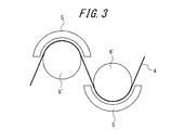
- FIG. 3 shows another example of the plasma nitriding apparatus according to the present invention.
- This example has a structure in which glow discharge is generated in a state in which the strip 4 is placed along an electrode roll 6 ′ arranged to face the positive electrode (glow discharge electrode) 5.
- the strip 4 is placed along an electrode roll 6 ′ arranged to face the positive electrode (glow discharge electrode) 5.
- the positive electrode glow discharge electrode
- only one surface of the strip 4 can be nitrided, so when nitriding is performed on both surfaces of the strip 4, another set of nitriding devices is required.
- the strip temperature is preferably raised to 400 ° C. or higher.
- the inside of the nitriding treatment zone is preferably kept under reduced pressure.
- the degree of vacuum is lower than the nitriding zone in the heating zone and the cooling zone, it is preferable to maintain a reduced pressure from the atmospheric pressure, which facilitates heat exchange by convection, Heating / cooling efficiency can be improved.
- the inside of the nitriding zone should be depressurized to about 0.5 to 10 Torr, which is suitable as a glow discharge condition, and the heating zone and the cooling zone should be depressurized to about 30 to 500 Torr, which is lower than that. It is preferable to keep it in each case.
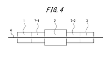
- FIG. 4 shows a case where the front atmosphere adjustment zone 7-1 and the rear atmosphere adjustment zone 7-2 are provided before and after the nitriding zone 2.
- the degree of pressure reduction gradually increases toward the nitriding treatment zone 2
- the latter stage atmosphere adjustment zone 7-2 the degree of pressure reduction gradually increases from the nitriding treatment zone 2 toward the cooling zone 3.
- what is necessary is just to use a conventionally well-known airtight sealing means for each zone and between each air chamber, and there exist methods, such as using a roll and a seal pad.
- the inside of the nitriding zone is preferably divided into a plurality of zones in the width direction of the strip, and the nitriding treatment can be performed independently in each divided zone.
- uneven nitriding in the width direction of the strip such as over-nitriding of the end due to the edge effect can be effectively eliminated.
- the heating zone may be omitted if the strip is already heated by being installed in a continuous line that performs other necessary processing, or if heating by plasma irradiation during plasma nitriding is sufficient. Is possible.
- the cooling zone may be disposed after the processing zone when other processing is performed in a heated state after the plasma nitriding processing.
- the nitriding equipment of the present invention may be an independent equipment that performs only the nitriding treatment continuously, but it may be attached to a process line that performs other treatment, and if it is a continuous line, it is optimal including efficiency. It only has to be attached to the appropriate place. And in this invention, there is no restriction
Landscapes
- Chemical & Material Sciences (AREA)
- Engineering & Computer Science (AREA)
- Materials Engineering (AREA)
- Mechanical Engineering (AREA)
- Metallurgy (AREA)
- Organic Chemistry (AREA)
- Physics & Mathematics (AREA)
- Thermal Sciences (AREA)
- Crystallography & Structural Chemistry (AREA)
- Chemical Kinetics & Catalysis (AREA)
- Electromagnetism (AREA)
- Manufacturing & Machinery (AREA)
- Dispersion Chemistry (AREA)
- Power Engineering (AREA)
- Manufacturing Of Steel Electrode Plates (AREA)
- Soft Magnetic Materials (AREA)
- Solid-Phase Diffusion Into Metallic Material Surfaces (AREA)
Abstract
Description
さらに、このようなガス窒化工程においてストリップ全体にわたり均一に窒化するために、ノズルまたはスプレーで供給する窒化ガスを鋼板中央部と鋼板両端部で分割して調整する方法が提案されている(特許文献7)。
また、特許文献5~7に開示された技術では、窒化性ガスを鋼板に吹付けて窒化する方法であるため、炉内温度の時間的・位置的な不均一や熱による配管中での窒化性ガスの分解量の違いなどにより、窒化増量がストリップの部所によって異なる場合があり、結果的に二次再結晶が不均一となり磁気特性の悪化につながる場合があった。
その結果、ストリップ(鋼板)に対して連続的に窒化処理する場合には、グロー放電を活用して窒化を施すことにより、窒化量の高精度な制御が可能となり、併せてそのバラツキも解消され、さらには処理時間の短縮も達成されて、優れた磁気特性が全ストリップ内で安定して得られるとの知見を得た。
そして、上記したようなグロー放電によるプラズマ窒化を、ストリップに対する窒化処理として施すために必要な設備として最適な構造を見出し、本発明を完成させるに至ったのである。
1.方向性電磁鋼板の製造ラインにおいて、冷間圧延後、二次再結晶焼鈍前に、連続して通板するストリップに対し連続的に窒化処理を施す設備であって、
ストリップに対し窒化処理を施す窒化処理ゾーンと、ストリップを冷却する冷却ゾーンと、必要に応じて該窒化処理ゾーンの前にストリップを加熱する加熱ゾーンとをそなえ、該窒化処理ゾーンには、グロー放電用の電極を設置し、このグロー放電用電極を正極として、陰極としたストリップに対しグロー放電によるプラズマ窒化処理を施す方向性電磁鋼板の窒化処理設備。
また、本方法によれば、窒素源として窒素ガスを用いることができるため、従来、ガス窒化の際に必要とされたアンモニアや、塩浴窒化を行う場合に必要とされるシアン系の塩など、環境上の問題が懸念される窒素源を用いる必要がないので、その産業的利用価値は極めて大きい。
図1に、本発明の窒化処理設備の好適例の概略を示す。図中、符号1は加熱ゾーン、2は窒化処理ゾーン、3は冷却ゾーンである。そして、4が、上記の構造になる窒化処理設備内を連続的に通板するストリップ(鋼板)である。なお、加熱ゾーンは、必要に応じて設ければよく、必ず必要というわけではない。
図2に、本発明に従うプラズマ窒化処理装置の好適例を示す。図中、符号5がグロー放電用の電極、6が電極ロールを兼ねたピンチロールであり、この例では、ストリップ4を挟んでその上下にグロー放電用電極5を配置した構造になっている。なお、窒化処理ゾーン2内は、窒素供給源として窒素ガスおよび水素ガスが充填されている。
そして、グロー放電用電極5を正極、ピンチロール(電極ロール)を介してストリップ4を陰極として、その間に電圧を印加し、ストリップ4の両側でグロー放電を生じさせることにより、プラズマ雰囲気中でストリップ4の両面を同時に窒化処理するのである。
また、窒化処理ゾーン内は、減圧下に保持しておくことが好ましい。
さらに、加熱ゾーンおよび冷却ゾーンは、窒化処理ゾーンよりも減圧度は低いものの、大気圧よりは減圧された状態に保持することが好適であり、これにより、対流による熱交換が進みやすくなって、加熱・冷却効率を向上させることができる。
ここで、窒化処理ゾーン内は、グロー放電条件として好適な0.5~10トール程度に減圧しておくことが、また加熱ゾーンおよび冷却ゾーンは、減圧度がそれよりも低い30~500トール程度に減圧しておくことがそれぞれ好ましい。
この場合、前段雰囲気調整ゾーン7-1および後段雰囲気調整ゾーン7-2はそれぞれ、個別に減圧度の調整が可能な複数の気室に分けておくことが好ましい。そして、前段雰囲気調整ゾーン7-1では、窒化処理ゾーン2に向かうにつれて漸次減圧度を高めていく一方、後段雰囲気調整ゾーン7-2では、窒化処理ゾーン2から冷却ゾーン3に向かうにつれて漸次減圧度を低減していく仕組みとするのが好適である。
なお、各ゾーン間および各気室間のシールは、従来から公知の気密シール手段を用いればよく、ロールを用いたり、シールパッドを用いる等の方法がある。
また、冷却ゾーンに関しても、プラズマ窒化処理後に加熱された状態で他の処理を施す場合などは、その処理ゾーンの後に配置してもよい。
さらに、本発明の窒化処理設備は、窒化処理のみを連続的に行う独立した設備としてもよいが、他の処理を施す工程ラインに取り付けても良く、連続ラインであれば効率面を含めて最適な箇所に取り付けていればよい。
そして、本発明において、被処理材であるストリップについては特に制限はなく、方向性電磁鋼ストリップであれば、従来から公知のストリップいずれもが適合する。
2 窒化処理ゾーン
3 冷却ゾーン
4 ストリップ(鋼板)
5 グロー放電用電極
6 ピンチロール(電極ロールを兼務)
6′ 電極ロール
7-1 前段雰囲気調整ゾーン
7-2 後段雰囲気調整ゾーン
Claims (8)
- 方向性電磁鋼板の製造ラインにおいて、冷間圧延後、二次再結晶焼鈍前に、連続して通板するストリップに対し連続的に窒化処理を施す設備であって、
ストリップに対し窒化処理を施す窒化処理ゾーンと、ストリップを冷却する冷却ゾーンと、必要に応じて該窒化処理ゾーンの前にストリップを加熱する加熱ゾーンとをそなえ、該窒化処理ゾーンには、グロー放電用の電極を設置し、このグロー放電用電極を正極として、陰極としたストリップに対しグロー放電によるプラズマ窒化処理を施す方向性電磁鋼板の窒化処理設備。 - 前記窒化処理ゾーンを減圧下に保持する請求項1に記載の方向性電磁鋼板の窒化処理設備。
- 前記加熱ゾーンおよび/または前記冷却ゾーンを、前記窒化処理ゾーンよりも減圧度が低く、かつ大気圧よりも減圧された状態に保持する請求項2に記載の方向性電磁鋼板の窒化処理設備。
- 前記加熱ゾーンと前記窒化処理ゾーンとの間に前段雰囲気調整ゾーンを設けると共に、前記窒化処理ゾーンと前記冷却ゾーンとの間に後段雰囲気調整ゾーンを設けた請求項1乃至3のいずれかに記載の方向性電磁鋼板の窒化処理設備。
- 前記前段雰囲気調整ゾーンおよび前記後段雰囲気調整ゾーンがそれぞれ、個別に減圧度の調整が可能な複数の気室に分かれている請求項4に記載の方向性電磁鋼板の窒化処理設備。
- 前記前段雰囲気調整ゾーンでは、前記窒化処理ゾーンに向かうにつれて漸次減圧度を高める一方、前記後段雰囲気調整ゾーンでは、前記冷却ゾーンに向かうにつれて漸次減圧度を低減する請求項5に記載の方向性電磁鋼板の窒化処理設備。
- 前記窒化処理ゾーンの内部を、ストリップの幅方向に複数のゾーンに分割し、各分割ゾーン内で個別の窒化処理制御を可能とした請求項1乃至6のいずれかに記載の方向性電磁鋼板の窒化処理設備。
- 方向性電磁鋼板の製造工程中、冷間圧延後、二次再結晶焼鈍前の段階において、請求項1乃至7のいずれかに記載の窒化処理設備を用いて、ストリップに対しグロー放電によるプラズマ窒化処理を施す方向性電磁鋼板の窒化処理方法。
Priority Applications (5)
| Application Number | Priority Date | Filing Date | Title |
|---|---|---|---|
| US14/761,707 US10066286B2 (en) | 2013-02-18 | 2014-02-18 | Apparatus and method for nitriding grain-oriented electrical steel sheet |
| KR1020157021977A KR20150108386A (ko) | 2013-02-18 | 2014-02-18 | 방향성 전기 강판의 질화 처리 설비 및 질화 처리 방법 |
| CN201480009247.8A CN105074044B (zh) | 2013-02-18 | 2014-02-18 | 方向性电磁钢板的氮化处理设备以及氮化处理方法 |
| RU2015139697A RU2615752C2 (ru) | 2013-02-18 | 2014-02-18 | Устройство и способ азотирования листа из текстурированной электротехнической стали |
| EP14751176.0A EP2957652B1 (en) | 2013-02-18 | 2014-02-18 | Apparatus and method for nitriding grain-oriented electrical steel sheet |
Applications Claiming Priority (2)
| Application Number | Priority Date | Filing Date | Title |
|---|---|---|---|
| JP2013029368A JP5942886B2 (ja) | 2013-02-18 | 2013-02-18 | 方向性電磁鋼板の窒化処理設備および窒化処理方法 |
| JP2013-029368 | 2013-02-18 |
Publications (2)
| Publication Number | Publication Date |
|---|---|
| WO2014125841A1 true WO2014125841A1 (ja) | 2014-08-21 |
| WO2014125841A8 WO2014125841A8 (ja) | 2015-08-06 |
Family
ID=51353852
Family Applications (1)
| Application Number | Title | Priority Date | Filing Date |
|---|---|---|---|
| PCT/JP2014/000820 Ceased WO2014125841A1 (ja) | 2013-02-18 | 2014-02-18 | 方向性電磁鋼板の窒化処理設備および窒化処理方法 |
Country Status (7)
| Country | Link |
|---|---|
| US (1) | US10066286B2 (ja) |
| EP (1) | EP2957652B1 (ja) |
| JP (1) | JP5942886B2 (ja) |
| KR (1) | KR20150108386A (ja) |
| CN (1) | CN105074044B (ja) |
| RU (1) | RU2615752C2 (ja) |
| WO (1) | WO2014125841A1 (ja) |
Families Citing this family (7)
| Publication number | Priority date | Publication date | Assignee | Title |
|---|---|---|---|---|
| JP5942884B2 (ja) | 2013-02-18 | 2016-06-29 | Jfeスチール株式会社 | 方向性電磁鋼板の窒化処理設備および窒化処理方法 |
| JP5942886B2 (ja) | 2013-02-18 | 2016-06-29 | Jfeスチール株式会社 | 方向性電磁鋼板の窒化処理設備および窒化処理方法 |
| CN104831040B (zh) * | 2015-05-25 | 2017-11-03 | 马钢(集团)控股有限公司 | 一种电工钢退火加热装置及其退火加热方法 |
| RU2654161C1 (ru) * | 2017-02-27 | 2018-05-16 | федеральное государственное бюджетное образовательное учреждение высшего образования "Уфимский государственный авиационный технический университет" | Способ локального ионного азотирования стальных изделий в тлеющем разряде с магнитным полем |
| CN110402007B (zh) * | 2019-07-31 | 2021-10-01 | 北京交通大学 | 一种基于空气辉光放电等离子体的材料表面处理装置 |
| CN111321369A (zh) * | 2020-03-05 | 2020-06-23 | 马鞍山钢铁股份有限公司 | 用于取向硅钢生产的离子氮化装置及其离子氮化方法 |
| CN117248176B (zh) * | 2023-10-20 | 2025-11-18 | 钢铁研究总院有限公司 | 一种板带在线连续渗氮装置 |
Citations (13)
| Publication number | Priority date | Publication date | Assignee | Title |
|---|---|---|---|---|
| US1965559A (en) | 1933-08-07 | 1934-07-03 | Cold Metal Process Co | Electrical sheet and method and apparatus for its manufacture and test |
| JPH02213460A (ja) * | 1989-02-15 | 1990-08-24 | Sumitomo Metal Ind Ltd | 表面特性の優れた鋼板の連続製造法と装置 |
| JPH03122227A (ja) | 1989-10-05 | 1991-05-24 | Nippon Steel Corp | 方向性電磁鋼板の脱炭連続焼鈍炉 |
| JPH046221A (ja) * | 1990-04-21 | 1992-01-10 | Nippon Steel Corp | 二方向性珪素鋼板の製造方法 |
| JPH04131376A (ja) * | 1990-09-21 | 1992-05-06 | Kawasaki Steel Corp | 差圧シール装置 |
| JPH04235222A (ja) * | 1991-01-08 | 1992-08-24 | Nippon Steel Corp | 磁束密度の高い方向性電磁鋼板の製造方法 |
| JPH08158038A (ja) * | 1994-11-29 | 1996-06-18 | Kawasaki Steel Corp | 金属帯の連続プラズマ処理装置 |
| JPH09118964A (ja) * | 1995-05-16 | 1997-05-06 | Armco Inc | 高い体積抵抗率を有する粒子方向性珪素鋼およびその製造法 |
| JP2771634B2 (ja) | 1989-10-05 | 1998-07-02 | 新日本製鐵株式会社 | 方向性電磁鋼板の脱炭連続焼鈍炉 |
| JP3940205B2 (ja) | 1997-06-30 | 2007-07-04 | 新日本製鐵株式会社 | 長手・幅方向偏差に小さい方向性電磁鋼板の窒化処理方法とそのための装置 |
| JP4015644B2 (ja) | 2004-05-31 | 2007-11-28 | 株式会社ソニー・コンピュータエンタテインメント | 画像処理装置及び画像処理方法 |
| JP4321120B2 (ja) | 2003-05-29 | 2009-08-26 | Jfeスチール株式会社 | 磁気特性に優れた方向性電磁鋼板の製造方法 |
| JP5113469B2 (ja) | 2006-09-29 | 2013-01-09 | 日本タングステン株式会社 | 炭化物粉末被覆酸化物粉末の製造方法 |
Family Cites Families (14)
| Publication number | Priority date | Publication date | Assignee | Title |
|---|---|---|---|---|
| US588314A (en) * | 1897-08-17 | Nut-lock | ||
| DE1252220B (ja) | 1963-04-05 | 1968-04-25 | ||
| JPS5113469B2 (ja) | 1972-10-13 | 1976-04-28 | ||
| US4109157A (en) * | 1975-12-18 | 1978-08-22 | Kawasaki Jukogyo Kabushiki Kaisha | Apparatus for ion-nitriding |
| DE2811942C2 (de) * | 1977-03-23 | 1986-09-18 | Vide et Traitement S.A., Neuilly-en-Thelle | Ofen zur ionischen Nitrierbehandlung von metallischen Werkstücken |
| JPH04136154A (ja) * | 1990-09-28 | 1992-05-11 | Sumitomo Heavy Ind Ltd | プラズマ処理装置 |
| JPH04198468A (ja) | 1990-11-29 | 1992-07-17 | Nkk Corp | 帯板の連続前処理装置 |
| EP0909832A1 (fr) * | 1997-10-17 | 1999-04-21 | RECHERCHE ET DEVELOPPEMENT DU GROUPE COCKERILL SAMBRE, en abrégé: RD-CS | Procédé pour la mise à composition d'un produit métallique |
| IT1316029B1 (it) * | 2000-12-18 | 2003-03-26 | Acciai Speciali Terni Spa | Processo per la produzione di acciaio magnetico a grano orientato. |
| DE10130308B4 (de) * | 2001-06-22 | 2005-05-12 | Thyssenkrupp Electrical Steel Ebg Gmbh | Kornorientiertes Elektroblech mit einer elektrisch isolierenden Beschichtung |
| RU2413033C2 (ru) * | 2009-01-11 | 2011-02-27 | Государственное учреждение Институт электрофизики Уральского отделения Российской академии наук | Способ плазменного азотирования изделия из стали или из цветного сплава |
| CN102650014B (zh) * | 2011-02-28 | 2014-08-13 | 新日铁住金株式会社 | 方向性电磁钢板的制造方法 |
| JP5942886B2 (ja) | 2013-02-18 | 2016-06-29 | Jfeスチール株式会社 | 方向性電磁鋼板の窒化処理設備および窒化処理方法 |
| US20140326182A1 (en) | 2013-05-03 | 2014-11-06 | Areesys Corporation | Continuous Substrate Processing Apparatus |
-
2013
- 2013-02-18 JP JP2013029368A patent/JP5942886B2/ja active Active
-
2014
- 2014-02-18 CN CN201480009247.8A patent/CN105074044B/zh active Active
- 2014-02-18 EP EP14751176.0A patent/EP2957652B1/en active Active
- 2014-02-18 US US14/761,707 patent/US10066286B2/en active Active
- 2014-02-18 RU RU2015139697A patent/RU2615752C2/ru active
- 2014-02-18 KR KR1020157021977A patent/KR20150108386A/ko not_active Ceased
- 2014-02-18 WO PCT/JP2014/000820 patent/WO2014125841A1/ja not_active Ceased
Patent Citations (13)
| Publication number | Priority date | Publication date | Assignee | Title |
|---|---|---|---|---|
| US1965559A (en) | 1933-08-07 | 1934-07-03 | Cold Metal Process Co | Electrical sheet and method and apparatus for its manufacture and test |
| JPH02213460A (ja) * | 1989-02-15 | 1990-08-24 | Sumitomo Metal Ind Ltd | 表面特性の優れた鋼板の連続製造法と装置 |
| JP2771634B2 (ja) | 1989-10-05 | 1998-07-02 | 新日本製鐵株式会社 | 方向性電磁鋼板の脱炭連続焼鈍炉 |
| JPH03122227A (ja) | 1989-10-05 | 1991-05-24 | Nippon Steel Corp | 方向性電磁鋼板の脱炭連続焼鈍炉 |
| JPH046221A (ja) * | 1990-04-21 | 1992-01-10 | Nippon Steel Corp | 二方向性珪素鋼板の製造方法 |
| JPH04131376A (ja) * | 1990-09-21 | 1992-05-06 | Kawasaki Steel Corp | 差圧シール装置 |
| JPH04235222A (ja) * | 1991-01-08 | 1992-08-24 | Nippon Steel Corp | 磁束密度の高い方向性電磁鋼板の製造方法 |
| JPH08158038A (ja) * | 1994-11-29 | 1996-06-18 | Kawasaki Steel Corp | 金属帯の連続プラズマ処理装置 |
| JPH09118964A (ja) * | 1995-05-16 | 1997-05-06 | Armco Inc | 高い体積抵抗率を有する粒子方向性珪素鋼およびその製造法 |
| JP3940205B2 (ja) | 1997-06-30 | 2007-07-04 | 新日本製鐵株式会社 | 長手・幅方向偏差に小さい方向性電磁鋼板の窒化処理方法とそのための装置 |
| JP4321120B2 (ja) | 2003-05-29 | 2009-08-26 | Jfeスチール株式会社 | 磁気特性に優れた方向性電磁鋼板の製造方法 |
| JP4015644B2 (ja) | 2004-05-31 | 2007-11-28 | 株式会社ソニー・コンピュータエンタテインメント | 画像処理装置及び画像処理方法 |
| JP5113469B2 (ja) | 2006-09-29 | 2013-01-09 | 日本タングステン株式会社 | 炭化物粉末被覆酸化物粉末の製造方法 |
Also Published As
| Publication number | Publication date |
|---|---|
| JP5942886B2 (ja) | 2016-06-29 |
| US20150361544A1 (en) | 2015-12-17 |
| WO2014125841A8 (ja) | 2015-08-06 |
| KR20150108386A (ko) | 2015-09-25 |
| CN105074044B (zh) | 2017-07-28 |
| EP2957652A1 (en) | 2015-12-23 |
| EP2957652B1 (en) | 2017-11-01 |
| RU2015139697A (ru) | 2017-03-23 |
| RU2615752C2 (ru) | 2017-04-11 |
| US10066286B2 (en) | 2018-09-04 |
| CN105074044A (zh) | 2015-11-18 |
| EP2957652A4 (en) | 2016-03-02 |
| JP2014156646A (ja) | 2014-08-28 |
Similar Documents
| Publication | Publication Date | Title |
|---|---|---|
| JP5942886B2 (ja) | 方向性電磁鋼板の窒化処理設備および窒化処理方法 | |
| US11198917B2 (en) | Method for nitriding grain-oriented electrical steel sheet | |
| CN105008555B (zh) | 方向性电磁钢板的制造方法 | |
| CN102812133A (zh) | 取向性电磁钢板的制造方法 | |
| EP3530770B1 (en) | Hot-rolled steel sheet for electrical steel sheet production and method of producing same | |
| CN108699621A (zh) | 取向性电磁钢板的制造方法 | |
| WO2014125840A1 (ja) | 方向性電磁鋼板の窒化処理方法および窒化処理装置 | |
| WO2013147155A1 (ja) | 炭素工具鋼鋼帯の製造方法 | |
| ITRM20000451A1 (it) | Procedimento per la regolazione della distribuzione degli inibitori nella produzione di lamierini magnetici a grano orientato. | |
| KR101908045B1 (ko) | 방향성 전기강판의 제조방법 | |
| JP6094504B2 (ja) | 方向性電磁鋼板の竪型窒化処理設備および窒化処理方法 | |
| JP5942885B2 (ja) | 方向性電磁鋼板の窒化処理方法および窒化処理装置 | |
| JP5896097B2 (ja) | 方向性電磁鋼板の仕上焼鈍方法および仕上焼鈍設備 | |
| JP5942887B2 (ja) | 方向性電磁鋼板の窒化処理方法および窒化処理装置 | |
| JP5434560B2 (ja) | 焼鈍分離剤および方向性電磁鋼板の仕上焼鈍方法 | |
| JPH03120318A (ja) | 一方向性電磁鋼帯の連続焼鈍設備 | |
| JP2003277830A (ja) | 板幅方向に均一な磁気特性を有する方向性電磁鋼板の製造方法 | |
| JPH04326A (ja) | 方向性けい素鋼板の鉄損低減用連続処理装置 | |
| KR20150074913A (ko) | 방향성 전기강판의 제조 방법 및 이 방법으로 제조된 방향성 전기강판 | |
| JP2010196080A (ja) | 方向性電磁鋼板の製造方法 |
Legal Events
| Date | Code | Title | Description |
|---|---|---|---|
| WWE | Wipo information: entry into national phase |
Ref document number: 201480009247.8 Country of ref document: CN |
|
| 121 | Ep: the epo has been informed by wipo that ep was designated in this application |
Ref document number: 14751176 Country of ref document: EP Kind code of ref document: A1 |
|
| WWE | Wipo information: entry into national phase |
Ref document number: 14761707 Country of ref document: US |
|
| REEP | Request for entry into the european phase |
Ref document number: 2014751176 Country of ref document: EP |
|
| WWE | Wipo information: entry into national phase |
Ref document number: 2014751176 Country of ref document: EP |
|
| ENP | Entry into the national phase |
Ref document number: 20157021977 Country of ref document: KR Kind code of ref document: A |
|
| NENP | Non-entry into the national phase |
Ref country code: DE |
|
| ENP | Entry into the national phase |
Ref document number: 2015139697 Country of ref document: RU Kind code of ref document: A |