WO2014125905A1 - Lame de scie - Google Patents
Lame de scie Download PDFInfo
- Publication number
- WO2014125905A1 WO2014125905A1 PCT/JP2014/051538 JP2014051538W WO2014125905A1 WO 2014125905 A1 WO2014125905 A1 WO 2014125905A1 JP 2014051538 W JP2014051538 W JP 2014051538W WO 2014125905 A1 WO2014125905 A1 WO 2014125905A1
- Authority
- WO
- WIPO (PCT)
- Prior art keywords
- tooth
- saw blade
- tip
- teeth
- succeeding
- Prior art date
- Legal status (The legal status is an assumption and is not a legal conclusion. Google has not performed a legal analysis and makes no representation as to the accuracy of the status listed.)
- Ceased
Links
Images


Classifications
-
- B—PERFORMING OPERATIONS; TRANSPORTING
- B23—MACHINE TOOLS; METAL-WORKING NOT OTHERWISE PROVIDED FOR
- B23D—PLANING; SLOTTING; SHEARING; BROACHING; SAWING; FILING; SCRAPING; LIKE OPERATIONS FOR WORKING METAL BY REMOVING MATERIAL, NOT OTHERWISE PROVIDED FOR
- B23D61/00—Tools for sawing machines or sawing devices; Clamping devices for these tools
- B23D61/02—Circular saw blades
- B23D61/04—Circular saw blades with inserted saw teeth, i.e. the teeth being individually inserted
-
- B—PERFORMING OPERATIONS; TRANSPORTING
- B23—MACHINE TOOLS; METAL-WORKING NOT OTHERWISE PROVIDED FOR
- B23D—PLANING; SLOTTING; SHEARING; BROACHING; SAWING; FILING; SCRAPING; LIKE OPERATIONS FOR WORKING METAL BY REMOVING MATERIAL, NOT OTHERWISE PROVIDED FOR
- B23D61/00—Tools for sawing machines or sawing devices; Clamping devices for these tools
- B23D61/12—Straight saw blades; Strap saw blades
- B23D61/14—Straight saw blades; Strap saw blades with inserted saw teeth, i.e. the teeth being individually inserted
Definitions
- the present invention relates to a saw blade having a hard chip at the tip [tips] of a saw tooth.
- a band saw machine is used to cut workpieces (metal materials).
- it is important to improve the accuracy of the cut surface by suppressing the vibration of the band saw blade in order to achieve higher efficiency in high-speed cutting (for example, cutting aluminum blocks at a saw speed of 1000 m / min or more). It is.
- the vibration suppression of the band saw blade in addition to improving the accuracy of the cut surface, it is possible to reduce noise, prevent tooth chipping, and improve the saw blade life.
- Some saw blades have set teeth that are bent sideways with respect to the cutting direction (feeding direction for band saw blades and rotating direction for circular saw blades [circular saw blade]) [set teeth ] Is provided.
- an unequal sawtooth pitch [variable tooth pitch] is employed in order to avoid sawtooth resonance.
- a saw blade having a dovetail-shaped [dovetail-shaped saw blade] is also used.
- Batachisari saw blades generally have a hard tip made of cemented carbide [cemented carbide], cermet [cermet], ceramic [ceramic], high-speed tool steel [high-speed tool steel], etc. I have.
- the hard tip generally has a symmetrical shape when viewed along the cutting direction of the workpiece. For example, there are various symmetrical shapes such as a trapezoid with a wide tip and a trapezoid with a narrow tip.
- the bevel-shaped sawtooth [dovetail tooth] that finishes the cut surface of the work has a low tooth height (dimension from the reference position to the tooth tip), and the tip has the widest shape on the side, The cut surface is finished at both ends of the leading edge.
- Patent Document 1 expands a trapezoidal leading tooth (indicated by “21” in FIG. 6) having a high tooth height and a narrow tip and a cutting groove formed by the leading tooth.
- Saw blades with [widen], flat teeth with low tooth height are disclosed. Since the cutting groove is expanded, a large cutting force acts on the spur teeth, and a large component force acts in the lateral direction due to this cutting resistance. Accordingly, the surface roughness Rmax (maximum height Rmax: JIS B 0601: 1982) of the cut surface is 30 ⁇ m (FIG. 9), and further improvement is desired for higher-precision finishing of the cut surface.
- Patent Document 2 also discloses a saw blade similar to the saw blade of Patent Document 1 (FIGS. 7 to 12).
- the leading teeth and the flat teeth in Patent Document 1 have the same height, and there is a problem similar to that of the saw blade in Patent Document 1.
- An object of the present invention is to provide a saw blade capable of finishing a cut surface with higher accuracy.
- a first feature of the present invention is a saw blade comprising a saw blade having a hard tip at a tip thereof, the saw tooth having a trapezoidal shape having a wide width in the thickness direction of the saw blade, A first trailing tooth having a first tip having chamfered portions formed at both ends of the flat tip edge; and a tip edge protruding from the tip edge of the first tip; A first leading tooth having a second tip that is narrower than the width of the first tip and whose tooth height is higher than the tooth height of the first tip and one chamfered portion of the first tip project in the width direction.
- a second succeeding tooth having a third tip having an acute angle portion and a tooth height equal to the tooth height of the first succeeding tooth, and a width direction from the other chamfered portion of the first tip.
- a third tip having a projected acute angle corner and having the same tooth height as the tooth height of the first succeeding tooth; Third and a trailing tooth, to provide a saw blade that.
- the saw tooth further includes a second leading tooth that widens a cutting groove formed by the first leading tooth, and the tooth height of the second leading tooth is lower than the tooth height of the first leading tooth. And it is preferable that it is higher than the tooth height of the first succeeding tooth.
- two or more first following teeth are provided in one sawtooth pattern.
- the total number of the second subsequent teeth and the third subsequent teeth is equal to or less than the total number of the first subsequent teeth, the first leading teeth, and the second leading teeth in one sawtooth pattern.
- the first to third chips are formed by grinding from chips having the same shape.
- each protrusion amount from the first tip of the acute angle portion of the second succeeding tooth and the third succeeding tooth is 4.0% or more and 8.5% or less of the saw width.
- the second succeeding tooth and the third succeeding tooth are arranged at the last part in the traveling direction of the saw tooth in one saw tooth pattern.
- a saw blade having a saw blade having a hard tip at a tip thereof, the saw blade first cutting the workpiece prior to cutting the workpiece, and the first leading tooth.
- a first succeeding tooth that widens a cutting groove formed by one preceding tooth; a second succeeding tooth and a third succeeding tooth that finishes a cut surface of the cutting groove widened by the first succeeding tooth; 1 following tooth has a trapezoidal shape whose tip is wide in the thickness direction of the saw blade, and has a flat tip edge and chamfered portions formed at both ends of the tip edge,
- the second succeeding tooth has an acute angle corner portion protruding in the thickness direction from one of the chamfered portions of the first succeeding tooth, and has the same tooth height as the tooth height of the first succeeding tooth.
- the third succeeding tooth is an acute angle portion protruding in the thickness direction from the other chamfered portion of the first succeeding tooth.
- the tooth heights of the second succeeding tooth and the third succeeding tooth are the same as the tooth height of the first succeeding tooth, and are disposed at both ends of the flat leading edge of the first succeeding tooth.
- the acute angle corners respectively protruding in the thickness direction from the formed chamfered portions finish the cut surface of the workpiece.
- the size of the chamfered portion of the first subsequent tooth is small, and the amount of protrusion from the chamfered portion of the acute angle portion is also small. For this reason, the cutting force acting on the second subsequent teeth and the third subsequent teeth is small, and the component force in the thickness direction during cutting is suppressed. As a result, the vibration is suppressed, and the opposing cut surfaces are finished with high accuracy by the second subsequent teeth and the third subsequent teeth.
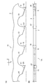
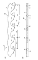
- (A) is a side view of the saw blade according to the first embodiment, and (B) is a bottom view of the saw blade.
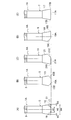
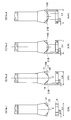
- (A) is a front view of the saw blade
- (B) is a front view of the preceding tooth
- (C) is a front view of the third succeeding tooth
- (D) is a front view of the second succeeding tooth.
- (E) is a front view of the first subsequent tooth.
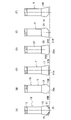
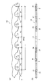
- (A) is a side view of the saw blade which concerns on 2nd Embodiment
- (B) is a bottom view of the said saw blade.
- (A) is a front view of the saw blade
- (B) is a front view of the (first) leading tooth
- (C) is a front view of the first trailing tooth
- (D) is the second leading tooth.
- It is a front view of a tooth
- (E) is a front view of a 3rd succeeding tooth
- (F) is a front view of a 2nd succeeding tooth.
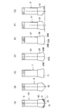
- (A) is a side view of the saw blade which concerns on 3rd Embodiment
- (B) is a bottom view of the said saw blade.
- (A) is a front view of the saw blade
- (B) is a front view of the (first) leading tooth
- (C) is a front view of the first trailing tooth
- (D) is the second leading tooth.
- (E) is a front view of a 3rd preceding tooth
- (F) is a front view of the 3rd succeeding tooth
- (G) is a front view of the 2nd succeeding tooth.
- It is a front view of a saw blade provided with a plurality of preceding teeth.
- (A) is a side view of a saw blade (2nd Embodiment)
- (B) is a bottom view of the said saw blade.
- (A) is a side view of a saw blade (3rd Embodiment)
- (B) is a bottom view of the said saw blade.
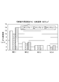
- (A)-(D) are front views of the saw blade used in the experiment. It is a graph which shows an experimental result.
- the saw blade 1 ⁇ / b> A of the first embodiment includes a base material [base material] (a band in the case of a band saw blade, and a disk in the case of a circular saw blade) 3. .
- base material a band in the case of a band saw blade, and a disk in the case of a circular saw blade
- saw blades 5, 7, 9 and 11 are formed at intervals like a general saw blade. Between each of the saw teeth 5, 7, 9 and 11, a gullet 13 is formed.
- a hard tip 15, 17, 19 or 21 made of cemented carbide, cermet, ceramic, high-speed tool steel or the like is fixed to each tip of the saw teeth 5, 7, 9 and 11.
- the saw tooth 5 is a first tooth 5 that cuts the work in advance.
- the tooth height of the leading tooth 5 (the height from the reference position of the base material 3 to the flat tip edge 15A of the hard tip (second tip) 15A (see FIG. 2 (B))) Highest of all.
- the hard tip 15 has a tip edge that is viewed from a cutting direction X (running direction for a band saw blade and rotational direction for a circular saw blade) perpendicular to the cutting direction [incisingincdirection] Z (see FIG. 1A). It is formed by grinding a trapezoidal chip with a wide width. That is, as shown in FIG. 2B, the inclined surfaces 15B are formed symmetrically on both sides of the tip edge 15A by grinding. The inclined surfaces 15B approach each other toward the tip edge 15A. In other words, the tip of the hard chip 15 has a trapezoidal shape with a narrow width.
- the saw blade 7 is a first trailing tooth 7 that expands the width W1 (see FIG. 2A) of the cutting groove formed by the leading teeth 5 to the width W2.
- the tooth height of the first succeeding tooth 7 (the height from the reference position of the base material 3 to the flat tip edge 17A of the hard tip (first tip) 17 (see FIG. 2E)) is the tooth of the preceding tooth 5. Lower than high.
- the hard tip 17 of the first succeeding tooth 7 is also formed by grinding the same trapezoidal tip as in the preceding tooth 5. That is, the tip edge 17A whose tooth height is lower than that of the preceding tooth 5 is formed by grinding, and chamfered edges 17B are formed symmetrically on both sides of the tip edge 17A.
- the chamfered portion 17 ⁇ / b> B is an inclined surface parallel to the inclined surface 15 ⁇ / b> B of the leading tooth 5.
- the size of the chamfered portion 17B is extremely smaller than the size of the inclined surface 15B.
- the sawtooth 9 is a second succeeding tooth 9 that slightly widens one side of the cutting groove formed by the first succeeding tooth 7 by a width W3.
- the saw tooth 11 is a third subsequent tooth 11 that slightly widens the other side of the cutting groove formed by the first subsequent tooth 7 by a width W3.
- the tooth height of the second succeeding tooth 9 (the height from the reference position of the base material 3 to the flat tip edge 19A of the hard tip (third tip) 19 (see FIG. 2D)) is the first succeeding tooth. Equal to 7 tooth height.
- the tooth height of the third subsequent tooth 11 (the height from the reference position of the base material 3 to the flat leading edge 21A of the hard tip (third tip) 21 (see FIG. 2C)) is also the first. It is equal to the tooth height of the subsequent tooth 7.
- the hard tip 19 of the second succeeding tooth 9 and the hard tip 21 of the third succeeding tooth 11 are formed by grinding the same trapezoidal tip as in the preceding tooth 5.
- the hard tip 19 and the hard tip 21 are cut symmetrically as shown in FIGS. 2D and 2C.
- a tip edge 19A having a tooth height lower than that of the preceding tooth 5 is formed by grinding, and one end of the tip edge 19A does not come into contact with one of the opposed cutting surfaces [ escape [surface] 19C is formed. Further, the other end of the tip edge 19A is not ground, and an acute angle corner [sharp corner] 19B for finishing the other of the opposed cut surfaces is formed.
- the acute angle portion 19B slightly protrudes from the chamfered portion 17B of the first subsequent tooth 7 as shown in FIG.
- tip edge 21A, the flank 21C, and the acute angle part 21B are formed symmetrically by grinding.
- the saw blade 1A has four types of saw teeth, and four saw teeth [(first) leading tooth 5, first trailing tooth 7, second trailing tooth 9 and third trailing tooth 11].
- One set pattern [set pattern] is configured. These four types of saw blades have two types of tooth heights.
- the leading tooth 5 has a symmetrical shape with respect to the center surface of the saw blade 1A (the inclined surface 15B is formed symmetrically), the saw blade 1A is cut in the cutting direction X by cutting the tip edge 15A. Be guided to. As a result, vibration in the thickness direction of the saw blade 1A perpendicular to the cutting direction X (lateral direction in FIGS. 2A to 2E) is suppressed, and excellent straightness without bending [superior straight- line stability].
- a cutting groove having a width W1 (see FIG. 2A) is straightly formed by the leading teeth 5, and the first succeeding teeth 7 are cut into the workpiece following the cutting by the leading teeth 5, and the cutting grooves are formed into the width W2. Expand to. Following the first succeeding tooth 7, the acute angle portions 19B and 21B of the second succeeding tooth 9 and the third succeeding tooth 11 cut the cut surfaces facing each other of the cutting groove by a width W3, respectively, and the cutting groove has a width W4. Expand to.
- the cutting width W3 it is also possible to set the cutting width W3 to 0.1 mm or less. As the cutting width W3 is reduced, the above-described component force is reduced, and the cut surface can be finished with higher accuracy. In consideration of wear of the saw blade 1A and the like, the cutting width W3 is preferably 0.03 mm or more.
- the cutting groove is expanded from the width W1 to the width W2 by the first subsequent teeth 7. Since the tooth heights of the second succeeding tooth 9 and the third succeeding tooth 11 are the same as the tooth height of the first succeeding tooth 7, the protruding amount of the cutting width W3 is extremely small. Therefore, the work load [workload] in the cutting direction by the second succeeding tooth 9 and the third succeeding tooth 11 is extremely small.
- the acute angle portions 19B and 21B of the second succeeding tooth 9 and the third succeeding tooth 11 act only on one side of the cut surface, and flank surfaces 19C and 21C are formed on the opposite side. For this reason, even if it receives a strong impact or a large cutting force in the lateral direction, the second succeeding tooth 9 and the third succeeding tooth 11 can be elastically deformed to the opposite side to prevent chipping. Since chipping is prevented, the cut surface can be finished with high accuracy. That is, since the second succeeding tooth 9 and the third succeeding tooth 11 finish the facing cut surfaces, they are not pinched between the facing cut surfaces.
- the saw blades disclosed in Patent Documents 1 and 2 described above are also provided with subsequent teeth that respectively cut the opposing cutting surfaces. Therefore, those succeeding teeth can also be elastically deformed by a large lateral force due to the above-mentioned cutting resistance.
- these saw teeth widen (rather than finish) the cutting groove formed by the leading teeth. That is, the sum of the cutting widths of the subsequent teeth is substantially equal to the cutting width of the preceding teeth.
- a large cutting resistance acts on the subsequent teeth, and the component force increases as described above.
- the saw blade easily generates vibrations in the lateral direction, and it is difficult to finish the cutting surface with high accuracy (surface roughness (Rmax) 30 ⁇ m or less) with the saw blade disclosed in Patent Documents 1 and 2 described above. .
- the leading tooth 5 having the tip edge 15A protruding from the tip edge 17A of the first succeeding tooth 7 and having the inclined surface 15B formed symmetrically is the workpiece first.
- the cutting results in good straightness and effective suppression of lateral vibration.
- the first succeeding tooth 7 widens the cutting groove formed by the preceding tooth 5, and the second succeeding tooth 9 and the third succeeding tooth 11 finish the cut surface (not widen the cutting groove).
- the second succeeding tooth 9 and the third succeeding tooth 11 have a saw blade exclusively for finishing that suppresses the lateral component force and finishes the cutting surface with high accuracy. Saw blade). Therefore, according to the saw blade 1A of the present embodiment, the cut surface can be finished with higher accuracy.
- [Second Embodiment] 3 and 4 show the saw blade 1B of the second embodiment.
- components having the same functions as those of the saw blade 1A of the first embodiment are denoted by the same reference numerals, and redundant description is omitted.
- the saw blade 1B of the present embodiment has a configuration in which a second leading tooth 23 (see FIG. 4D) is added between the first trailing tooth 7 and the second trailing tooth 9 in the saw blade 1A of the first embodiment. It has.
- the tooth height of the second leading tooth 23 is lower than the tooth height of the (first) leading tooth 5 and higher than the tooth height of the first trailing tooth 7.
- the hard tip (fourth tip) 25 of the second leading tooth 23 has a flat leading edge 25A that is wider than the leading edge 15A of the leading tooth 5. Both ends of the leading edge 25A protrude laterally from the inclined surface 15B of the leading tooth 5 (see FIGS. 4A, 4B, and 4D).
- inclined surfaces 25B parallel to the inclined surface 15B are formed symmetrically at both ends of the leading edge 25A (see FIG. 4D).
- the saw blade 1B has five types of saw teeth, and five saw teeth [(first) leading teeth 5, first trailing teeth 7, second leading teeth 23, second trailing teeth 9 and third trailing teeth. Tooth 11] constitutes one set pattern. These five types of saw blades have three types of tooth heights.
- the saw blade 1B has three symmetrically shaped saw teeth [leading tooth 5, first succeeding tooth 7 and second leading tooth 23] in one set pattern, which is more than the saw blade 1A of the first embodiment. Many. For this reason, lateral vibration is suppressed more effectively, and better straightness is provided. Further, since there are many types of saw blades in the saw blade 1B, the cutting role is more finely divided and the cutting resistance is reduced. For this reason, vibration is suppressed.
- the cut surface can be finished with higher accuracy than the saw blade 1A of the first embodiment. Further, according to the saw blade 1B, the cutting resistance is further suppressed, so that the life of the saw blade is further improved and cutting can be performed with high efficiency.
- FIG. 5 and 6 show a saw blade 1C of the third embodiment.
- the same reference numerals are given to components having the same functions as those of the saw blade 1A or 1B of the above embodiment, and redundant description is omitted.
- the saw blade 1 ⁇ / b> C of the present embodiment includes another first succeeding tooth 7 and the third third tooth between the second succeeding tooth 23 and the second succeeding tooth 9 in the saw blade 1 ⁇ / b> B of the second embodiment.
- gear 27 (refer FIG.5 (E)) is provided.
- the tooth height of the third leading tooth 27 is lower than the tooth height of the (first) leading tooth 5 and higher than the tooth height of the first trailing tooth 7 (that is, equal to the tooth height of the second leading tooth 23).
- the hard tip (fifth tip) 29 of the third leading tooth 27 has a flat leading edge 29A that is wider than the leading edge 25A of the second leading tooth 23.
- Both ends of the leading edge 29A protrude laterally from the inclined surface 25B of the second leading tooth 23 (see FIGS. 5A, 5D, and 5E).
- inclined surfaces 29B parallel to the inclined surfaces 25B are formed symmetrically at both ends of the leading edge 29A (see FIG. 5E).
- the saw blade 1 ⁇ / b> C has six types of saw teeth, and seven saw teeth [(first) leading tooth 5, first trailing tooth 7, second leading tooth 23, first trailing tooth 7, third leading tooth.
- the teeth 27, the second succeeding teeth 9 and the third succeeding teeth 11] constitute one set pattern.
- These six types of saw blades have three types of tooth heights.
- the third leading tooth 27 further widens the cutting groove widened by the second leading tooth 23.
- the saw blade 1C includes saw teeth [(first) leading tooth 5, second leading tooth 23, third leading tooth 27, and first trailing tooth 7] in which the width of the leading edge becomes wider as the tooth height decreases. The cutting force is distributed over these saw teeth. Therefore, the cutting resistance is further suppressed, and the vibration caused by the cutting resistance can be more effectively suppressed.
- the saw blade 1C has five symmetrical sawtooths [leading tooth 5, first trailing tooth 7, second leading tooth 23, first trailing tooth 7 and third leading tooth 27] in one set pattern. More than the saw blade 1B of the second embodiment. For this reason, lateral vibration is further effectively suppressed, and better straightness is provided. Further, since the saw blade 1C has the two first subsequent teeth 7 in one set pattern, the cutting amounts of the second subsequent teeth 9 and the third subsequent teeth 11 are reduced and the cutting resistance is further reduced. To do. For this reason, the vibration resulting from cutting resistance is further suppressed by the cutting resistance reduction of a cutting direction. As a result, according to the saw blade 1C, the cut surface can be finished with higher accuracy.
- the cutting amounts of the tip edges 19A and 21A are substantially zero, and the cut surfaces are finished at the acute angle portions 19B and 21B. . That is, since the second succeeding tooth 9 and the third succeeding tooth 11 substantially only finish the cut surface, the saw blade 1C can finish the cut surface with higher accuracy.
- leading teeth having a tip edge at the tip of the hard tip and inclined surfaces on both sides of the tip edge in one set pattern ( A hard tip 35 having a fourth leading tooth is added to the above-described saw blade 1C), and the cutting resistance is distributed to each saw tooth to further suppress vibrations and provide better straightness. Note that the number of leading teeth in one set pattern can be arbitrarily determined.
- FIGS. 8A and 8B show the saw blade 1B of the second embodiment described above.
- one clam pattern was constituted by five saw teeth.
- the pitches P1 to P3 are repeated [three pitch patterns PP (3)].
- a complicated sawtooth pattern can be realized by making the number of pitch patterns different from the number of clam patterns.
- FIGS. 9A and 9B show the saw blade 1C of the third embodiment described above.
- One clam pattern was composed of seven saw teeth.
- a more complex sawtooth pattern can be realized by making the number of pitch patterns different from the number of clam patterns and increasing the number.
- the saw blade No. 1 shown in FIGS. 1-No. 4 was used.
- the saw blade 1 has a first leading tooth 5, a second leading tooth 23, and a bee-shaped hard chip (dovetail hard chip) that simultaneously contacts both side cut surfaces.
- a bevel saw blade 31 is provided.
- Each protrusion amount from the second leading tooth 23 at the acute angle portion of the bevel saw blade 31 is 0.28 mm (total protrusion amount on both sides: 0.56 mm / expands about 23% of the entire width of the cutting groove).
- No. 2 to No. The saw blade 4 has the same sawtooth pattern as the saw blade 1B of the second embodiment shown in FIGS. 3 (A) to 4 (F).
- no. 2 to No. No. 4 saw blade 5 (hard tip 15) tooth height No. 4 The saw blade 5 (hard tip 15) in one saw blade has the same tooth height.
- No. 2 to No. No. 4 saw blade 7 (hard tip 17) tooth height No. 4 The saw blade 7 (hard chip 17) in one saw blade has the same tooth height.
- No. 2 to No. No. 4 saw blade 23 (hard tip 25) tooth height, No. 4 The saw blade 31 of one saw blade has the same tooth height.
- the protruding amount of the acute angle portion 19B of the hard tip 19 (second succeeding tooth 9) in the saw blade 2 from the hard tip 17 (first succeeding tooth 7) is 0.20 mm
- the amount of protrusion of the acute angle portion 19B from the hard tip 17 in the saw blade 3 is 0.10 mm, and the amount of protrusion of the acute angle portion 21B from the hard tip 17 is also 0.10 mm. That is, the hard tips 19 and 21 (total protrusion amount on both sides: 0.20 mm) expand about 8.3% of the cutting groove width.
- the amount of protrusion of the acute angle portion 19B from the hard tip 17 in the saw blade 4 is 0.05 mm, and the amount of protrusion of the acute angle portion 21B from the hard tip 17 is also 0.05 mm. That is, the hard tips 19 and 21 (total protrusion amount on both sides: 0.10 mm) expand about 4.2% of the cutting groove width.
- W shown by FIG. 10 (A) is a work amount of the cutting direction of each sawtooth.
- the rectangular area represents the work amount of the acute angle portion. That is, the smaller the area, the smaller the work amount.
- No. 1-No. Three saw blades of 4 were prepared with the same material and the same tooth profile, and numbered as Samples 1 to 3.
- the workpiece is an aluminum square (cross-sectional dimension of the workpiece as viewed from the workpiece feeding direction: 1680 mm ⁇ 1680 mm).
- Cutting conditions are a saw speed of 2000 m / min, a workpiece feed speed of 300 mm / min, a band saw blade width of 80 mm, a band saw blade base material thickness of 1.6 mm, and 0.5 / 0.8 P (variable pitch). .
- the surface roughness Ra (arithmetic average roughness Ra: JIS B 0601: 2001 / ISO 4287: 1997) when the cut area was 1 million cm 2 was measured.
- the graph in FIG. 11 shows the measurement results.
- the surface roughness Ra of one saw blade is about 12 ⁇ m on average.
- no. The surface roughness Ra of the saw blade 2 is an average of about 4.7 ⁇ m.
- No. No. 3 saw blades have an average surface roughness Ra of about 3.0 ⁇ m.
- the surface roughness Ra of No. 4 saw blade is about 2.7 ⁇ m on average.
- the Rmax roughness classification 6.3S is regarded as a “good machine finish surface”, and this Rmax is determined according to “20.
- Rmax 6.3S corresponds to three triangular symbols and is more accurate than the arithmetic average roughness (Ra) of 3.2 because it is the value of the maximum height (Rz) in the “surface roughness value correspondence table”. It means that. In other words, No. with Ra of 3.0 ⁇ m or less. 3 and no. 4 indicates that a “good machine finish surface” is achieved.
- each protrusion amount of the second succeeding tooth 9 and the third succeeding tooth 11 from the hard tip 17 is 4.0% or more and 8.5% or less of the saw width.
- the acute angle corners 19B and 21B of the second subsequent tooth 9 and the third subsequent tooth 11 from the chamfered portion 17B of the first subsequent tooth 7 are protruded in the lateral direction, so that the facing cut surfaces are finished with high accuracy. be able to.
- the 1st succeeding tooth 7 is provided with the chamfered part 17B in both sides, brings about a favorable straightness, and a cut surface is also cut comparatively favorable. After that, the cut surface cut relatively well by the first subsequent teeth 7 is finished better (with high definition) by the acute angle corners 19B and 21B of the second subsequent teeth 9 and the third subsequent teeth 11. . Therefore, the accuracy of the cut surface is further improved.
- the sawtooth “clam” is formed by the hard tip.
- the saw blade instead of the saw blade having a hard tip, it is considered to provide a clam tooth [two set teeth] (a saw blade formed by bending the saw blade itself).
- two set teeth that is, one set tooth having a set corresponding to one chamfer 17B of the hard tip 17, and the other set chamfer 17B are equivalent.
- another set of teeth on which a set is formed.
- two finishing set teeth are provided instead of the second succeeding tooth 9 and the third succeeding tooth 11. The tips of these finishing set teeth (corresponding to the acute angle portions 19B and 21B) protrude more laterally than the set teeth corresponding to the first subsequent teeth 7 described above.
- the cutting groove cut by the preceding tooth is expanded by the set tooth (corresponding to the first succeeding tooth 7). Then, the facing cut surfaces of the expanded cutting groove are finished by finishing set teeth.
- the set teeth expand the cutting groove, a large cutting force acts on the set teeth, and a large component force acts in the lateral direction due to the cutting resistance. Therefore, the cut surface cut by the set teeth is likely to be rough under the influence of the vibration caused by the above-described component force.
- the present invention is not limited to the above-described embodiment.
- the present invention is applied to a band saw blade, but can also be applied to a band saw blade.
Landscapes
- Engineering & Computer Science (AREA)
- Mechanical Engineering (AREA)
- Sawing (AREA)
Abstract
La présente invention concerne une lame de scie comportant des dents de scie dont les extrémités présentent une pointe dure. Les dents de scie comportent : des premières dents de bord de fuite présentant des premières pointes ayant une forme trapézoïde et donc leurs pointes sont plus larges dans la direction d'épaisseur de la lame de scie, et comprenant une section biseautée formée aux deux extrémités d'un bord de pointes plat de celle-ci ; des premières dents de bord d'attaque présentant des secondes pointes comprenant un bord de pointes en saillie depuis le bord de pointes des premières pointes, ayant un bord de pointes en saillie depuis le bord de pointes des premières pointes, ayant une largeur de bord de pointes qui est plus étroite que la largeur des premières pointes, et ayant une hauteur de dents qui supérieure à la hauteur de dents des première pointes ; des secondes dents de bord de fuite comprenant des troisièmes pointes comprenant une section de coin à angle aigu en saillie dans la direction de largeur depuis une section biseautée des première pointes et ayant la même hauteur de dents que la hauteur des dents des premières dents de bord de fuite ; et des troisièmes dents de bord de fuite comprenant des troisièmes pointes comprenant une section de coin à angle aigu en saillie dans la direction de largeur depuis l'autre section biseautée des premières pointes et ayant la même hauteur de dents que la hauteur de dents des premières dents de bord de fuite. Une surface de coupe peut être soumise à une finition plus précise grâce à la configuration de cette lame de scie.
Priority Applications (1)
| Application Number | Priority Date | Filing Date | Title |
|---|---|---|---|
| CN201490000424.1U CN204867639U (zh) | 2013-02-14 | 2014-01-24 | 锯条 |
Applications Claiming Priority (2)
| Application Number | Priority Date | Filing Date | Title |
|---|---|---|---|
| JP2013-026684 | 2013-02-14 | ||
| JP2013026684 | 2013-02-14 |
Publications (1)
| Publication Number | Publication Date |
|---|---|
| WO2014125905A1 true WO2014125905A1 (fr) | 2014-08-21 |
Family
ID=51353915
Family Applications (1)
| Application Number | Title | Priority Date | Filing Date |
|---|---|---|---|
| PCT/JP2014/051538 Ceased WO2014125905A1 (fr) | 2013-02-14 | 2014-01-24 | Lame de scie |
Country Status (3)
| Country | Link |
|---|---|
| JP (1) | JP6349090B2 (fr) |
| CN (1) | CN204867639U (fr) |
| WO (1) | WO2014125905A1 (fr) |
Cited By (3)
| Publication number | Priority date | Publication date | Assignee | Title |
|---|---|---|---|---|
| CN108367370A (zh) * | 2015-12-10 | 2018-08-03 | 株式会社天田控股集团 | 实现了主体部件长寿命化的带锯刀的制造方法及带锯刀 |
| CN113118555A (zh) * | 2021-05-14 | 2021-07-16 | 广东日东工具有限公司 | 新型铝用锯片 |
| WO2022048340A1 (fr) * | 2020-09-02 | 2022-03-10 | 湖南泰嘉新材料科技股份有限公司 | Lame de scie à ruban à séparation de dents |
Families Citing this family (8)
| Publication number | Priority date | Publication date | Assignee | Title |
|---|---|---|---|---|
| DE102015116747B3 (de) * | 2015-10-02 | 2017-03-30 | WIKUS-Sägenfabrik Wilhelm H. Kullmann GmbH & Co. KG | Sägeblatt mit einem Spanteilerzahn |
| JP6337169B1 (ja) * | 2017-02-24 | 2018-06-06 | 株式会社アマダホールディングス | 硬質チップ帯鋸刃 |
| CN109794645A (zh) * | 2019-03-14 | 2019-05-24 | 华侨大学 | 一种齿锯条 |
| CN110480095B (zh) * | 2019-08-13 | 2020-07-10 | 湖南泰嘉新材料科技股份有限公司 | 一种带锯条 |
| CN110899842B (zh) * | 2019-12-09 | 2023-12-15 | 辽宁东铄新材料科技有限公司 | 一种组合带锯条及其制造方式 |
| CN111054977B (zh) * | 2020-01-13 | 2020-08-21 | 湖南泰嘉新材料科技股份有限公司 | 一种多屑型带锯条 |
| JP7578680B2 (ja) * | 2020-04-13 | 2024-11-06 | 兼房株式会社 | チップソー |
| CN111715941A (zh) * | 2020-05-28 | 2020-09-29 | 新昌县智超邦金属材料科学技术研究院 | 一种双金属磨路带锯条 |
Citations (3)
| Publication number | Priority date | Publication date | Assignee | Title |
|---|---|---|---|---|
| JPH0639631A (ja) * | 1992-01-10 | 1994-02-15 | Wilhelm H Kullmann Wikus Saegenfab | 鋸 刃 |
| JPH0715224U (ja) * | 1993-07-22 | 1995-03-14 | 天龍製鋸株式会社 | 金属切断用回転鋸 |
| JP2005169546A (ja) * | 2003-12-10 | 2005-06-30 | Amada Co Ltd | 鋸刃 |
Family Cites Families (3)
| Publication number | Priority date | Publication date | Assignee | Title |
|---|---|---|---|---|
| DE3049018A1 (de) * | 1980-12-24 | 1982-07-22 | Gerd Höptner | "mit hartmetallplatten bestuecktes bandsaegeblatt" |
| JP2000254821A (ja) * | 1999-03-05 | 2000-09-19 | Tenryu Saw Mfg Co Ltd | 回転鋸 |
| US6520722B2 (en) * | 1999-07-21 | 2003-02-18 | Simonds Industries, Inc. | Asymmetrical cutting tool tooth form |
-
2014
- 2014-01-17 JP JP2014006444A patent/JP6349090B2/ja active Active
- 2014-01-24 CN CN201490000424.1U patent/CN204867639U/zh not_active Expired - Lifetime
- 2014-01-24 WO PCT/JP2014/051538 patent/WO2014125905A1/fr not_active Ceased
Patent Citations (3)
| Publication number | Priority date | Publication date | Assignee | Title |
|---|---|---|---|---|
| JPH0639631A (ja) * | 1992-01-10 | 1994-02-15 | Wilhelm H Kullmann Wikus Saegenfab | 鋸 刃 |
| JPH0715224U (ja) * | 1993-07-22 | 1995-03-14 | 天龍製鋸株式会社 | 金属切断用回転鋸 |
| JP2005169546A (ja) * | 2003-12-10 | 2005-06-30 | Amada Co Ltd | 鋸刃 |
Cited By (4)
| Publication number | Priority date | Publication date | Assignee | Title |
|---|---|---|---|---|
| CN108367370A (zh) * | 2015-12-10 | 2018-08-03 | 株式会社天田控股集团 | 实现了主体部件长寿命化的带锯刀的制造方法及带锯刀 |
| CN108367370B (zh) * | 2015-12-10 | 2021-06-01 | 株式会社天田控股集团 | 实现了主体部件长寿命化的带锯刀的制造方法及带锯刀 |
| WO2022048340A1 (fr) * | 2020-09-02 | 2022-03-10 | 湖南泰嘉新材料科技股份有限公司 | Lame de scie à ruban à séparation de dents |
| CN113118555A (zh) * | 2021-05-14 | 2021-07-16 | 广东日东工具有限公司 | 新型铝用锯片 |
Also Published As
| Publication number | Publication date |
|---|---|
| JP6349090B2 (ja) | 2018-06-27 |
| CN204867639U (zh) | 2015-12-16 |
| JP2014176956A (ja) | 2014-09-25 |
Similar Documents
| Publication | Publication Date | Title |
|---|---|---|
| WO2014125905A1 (fr) | Lame de scie | |
| KR100703145B1 (ko) | 톱날 | |
| JP4578577B2 (ja) | 切削インサート、切削工具、およびそれらを用いる切削方法 | |
| US4827822A (en) | Saw blade | |
| JP5600473B2 (ja) | 帯鋸刃 | |
| CA2643831C (fr) | Lame de scie avec tranchants arrondis | |
| JP2004338083A (ja) | 帯鋸ブレード | |
| JP5592954B2 (ja) | 切削インサートおよび切削工具、並びにそれを用いた切削加工物の製造方法 | |
| CN107530800A (zh) | 圆锯 | |
| US12257640B2 (en) | Recip blade | |
| JP6726853B2 (ja) | チップセパレータ歯を備える帯鋸 | |
| US20150367433A1 (en) | Saw blade having integrated swarf space | |
| WO2017099108A1 (fr) | Procédé de production d'une lame de scie à ruban qui prolonge la durée de vie de l'élément de cylindre, et lame de scie à ruban | |
| JP2001259927A (ja) | 鋸 刃 | |
| JP6337169B1 (ja) | 硬質チップ帯鋸刃 | |
| US8714059B2 (en) | Saw blade with single level and multiple level set patterns within pitch patterns, and related method | |
| CN105377490A (zh) | 用于切削加工工件的工具以及工具机 | |
| JP6251550B2 (ja) | 鋸刃及び鋸刃を用いた被切断材の切断方法 | |
| EP1586401A1 (fr) | Lame de scie à ruban et procédé de fabrication d'une lame de scie à ruban | |
| CN102430812A (zh) | 锯片 | |
| JP5592093B2 (ja) | 鋸刃 | |
| JP3283753B2 (ja) | 鋸 刃 | |
| JP2012056067A (ja) | 金属切断用丸鋸 | |
| JP4559145B2 (ja) | 帯鋸刃 | |
| JPS61230811A (ja) | 鋸刃 |
Legal Events
| Date | Code | Title | Description |
|---|---|---|---|
| 121 | Ep: the epo has been informed by wipo that ep was designated in this application |
Ref document number: 14751731 Country of ref document: EP Kind code of ref document: A1 |
|
| NENP | Non-entry into the national phase |
Ref country code: DE |
|
| 122 | Ep: pct application non-entry in european phase |
Ref document number: 14751731 Country of ref document: EP Kind code of ref document: A1 |