WO2014126220A1 - Noyau magnétique annulaire utilisant un alliage magnétique doux nanocristallin à base de fer et constituant magnétique utilisant ledit noyau magnétique annulaire - Google Patents
Noyau magnétique annulaire utilisant un alliage magnétique doux nanocristallin à base de fer et constituant magnétique utilisant ledit noyau magnétique annulaire Download PDFInfo
- Publication number
- WO2014126220A1 WO2014126220A1 PCT/JP2014/053536 JP2014053536W WO2014126220A1 WO 2014126220 A1 WO2014126220 A1 WO 2014126220A1 JP 2014053536 W JP2014053536 W JP 2014053536W WO 2014126220 A1 WO2014126220 A1 WO 2014126220A1
- Authority
- WO
- WIPO (PCT)
- Prior art keywords
- magnetic
- magnetic core
- annular
- atomic
- frequency
- Prior art date
- Legal status (The legal status is an assumption and is not a legal conclusion. Google has not performed a legal analysis and makes no representation as to the accuracy of the status listed.)
- Ceased
Links
Images








Classifications
-
- C—CHEMISTRY; METALLURGY
- C22—METALLURGY; FERROUS OR NON-FERROUS ALLOYS; TREATMENT OF ALLOYS OR NON-FERROUS METALS
- C22C—ALLOYS
- C22C38/00—Ferrous alloys, e.g. steel alloys
-
- C—CHEMISTRY; METALLURGY
- C21—METALLURGY OF IRON
- C21D—MODIFYING THE PHYSICAL STRUCTURE OF FERROUS METALS; GENERAL DEVICES FOR HEAT TREATMENT OF FERROUS OR NON-FERROUS METALS OR ALLOYS; MAKING METAL MALLEABLE, e.g. BY DECARBURISATION OR TEMPERING
- C21D1/00—General methods or devices for heat treatment, e.g. annealing, hardening, quenching or tempering
- C21D1/74—Methods of treatment in inert gas, controlled atmosphere, vacuum or pulverulent material
-
- C—CHEMISTRY; METALLURGY
- C21—METALLURGY OF IRON
- C21D—MODIFYING THE PHYSICAL STRUCTURE OF FERROUS METALS; GENERAL DEVICES FOR HEAT TREATMENT OF FERROUS OR NON-FERROUS METALS OR ALLOYS; MAKING METAL MALLEABLE, e.g. BY DECARBURISATION OR TEMPERING
- C21D1/00—General methods or devices for heat treatment, e.g. annealing, hardening, quenching or tempering
- C21D1/78—Combined heat-treatments not provided for above
-
- C—CHEMISTRY; METALLURGY
- C21—METALLURGY OF IRON
- C21D—MODIFYING THE PHYSICAL STRUCTURE OF FERROUS METALS; GENERAL DEVICES FOR HEAT TREATMENT OF FERROUS OR NON-FERROUS METALS OR ALLOYS; MAKING METAL MALLEABLE, e.g. BY DECARBURISATION OR TEMPERING
- C21D9/00—Heat treatment, e.g. annealing, hardening, quenching or tempering, adapted for particular articles; Furnaces therefor
- C21D9/0068—Heat treatment, e.g. annealing, hardening, quenching or tempering, adapted for particular articles; Furnaces therefor for particular articles not mentioned below
-
- C—CHEMISTRY; METALLURGY
- C22—METALLURGY; FERROUS OR NON-FERROUS ALLOYS; TREATMENT OF ALLOYS OR NON-FERROUS METALS
- C22C—ALLOYS
- C22C38/00—Ferrous alloys, e.g. steel alloys
- C22C38/002—Ferrous alloys, e.g. steel alloys containing In, Mg, or other elements not provided for in one single group C22C38/001 - C22C38/60
-
- C—CHEMISTRY; METALLURGY
- C22—METALLURGY; FERROUS OR NON-FERROUS ALLOYS; TREATMENT OF ALLOYS OR NON-FERROUS METALS
- C22C—ALLOYS
- C22C38/00—Ferrous alloys, e.g. steel alloys
- C22C38/02—Ferrous alloys, e.g. steel alloys containing silicon
-
- C—CHEMISTRY; METALLURGY
- C22—METALLURGY; FERROUS OR NON-FERROUS ALLOYS; TREATMENT OF ALLOYS OR NON-FERROUS METALS
- C22C—ALLOYS
- C22C38/00—Ferrous alloys, e.g. steel alloys
- C22C38/08—Ferrous alloys, e.g. steel alloys containing nickel
-
- C—CHEMISTRY; METALLURGY
- C22—METALLURGY; FERROUS OR NON-FERROUS ALLOYS; TREATMENT OF ALLOYS OR NON-FERROUS METALS
- C22C—ALLOYS
- C22C38/00—Ferrous alloys, e.g. steel alloys
- C22C38/12—Ferrous alloys, e.g. steel alloys containing tungsten, tantalum, molybdenum, vanadium, or niobium
-
- C—CHEMISTRY; METALLURGY
- C22—METALLURGY; FERROUS OR NON-FERROUS ALLOYS; TREATMENT OF ALLOYS OR NON-FERROUS METALS
- C22C—ALLOYS
- C22C38/00—Ferrous alloys, e.g. steel alloys
- C22C38/16—Ferrous alloys, e.g. steel alloys containing copper
-
- C—CHEMISTRY; METALLURGY
- C22—METALLURGY; FERROUS OR NON-FERROUS ALLOYS; TREATMENT OF ALLOYS OR NON-FERROUS METALS
- C22C—ALLOYS
- C22C38/00—Ferrous alloys, e.g. steel alloys
- C22C38/18—Ferrous alloys, e.g. steel alloys containing chromium
- C22C38/32—Ferrous alloys, e.g. steel alloys containing chromium with boron
-
- C—CHEMISTRY; METALLURGY
- C22—METALLURGY; FERROUS OR NON-FERROUS ALLOYS; TREATMENT OF ALLOYS OR NON-FERROUS METALS
- C22C—ALLOYS
- C22C45/00—Amorphous alloys
- C22C45/02—Amorphous alloys with iron as the major constituent
-
- H—ELECTRICITY
- H01—ELECTRIC ELEMENTS
- H01F—MAGNETS; INDUCTANCES; TRANSFORMERS; SELECTION OF MATERIALS FOR THEIR MAGNETIC PROPERTIES
- H01F1/00—Magnets or magnetic bodies characterised by the magnetic materials therefor; Selection of materials for their magnetic properties
- H01F1/01—Magnets or magnetic bodies characterised by the magnetic materials therefor; Selection of materials for their magnetic properties of inorganic materials
- H01F1/03—Magnets or magnetic bodies characterised by the magnetic materials therefor; Selection of materials for their magnetic properties of inorganic materials characterised by their coercivity
- H01F1/12—Magnets or magnetic bodies characterised by the magnetic materials therefor; Selection of materials for their magnetic properties of inorganic materials characterised by their coercivity of soft-magnetic materials
- H01F1/14—Magnets or magnetic bodies characterised by the magnetic materials therefor; Selection of materials for their magnetic properties of inorganic materials characterised by their coercivity of soft-magnetic materials metals or alloys
- H01F1/147—Alloys characterised by their composition
- H01F1/153—Amorphous metallic alloys, e.g. glassy metals
- H01F1/15333—Amorphous metallic alloys, e.g. glassy metals containing nanocrystallites, e.g. obtained by annealing
-
- H—ELECTRICITY
- H01—ELECTRIC ELEMENTS
- H01F—MAGNETS; INDUCTANCES; TRANSFORMERS; SELECTION OF MATERIALS FOR THEIR MAGNETIC PROPERTIES
- H01F3/00—Cores, Yokes, or armatures
- H01F3/04—Cores, Yokes, or armatures made from strips or ribbons
Definitions
- the present invention relates to an annular magnetic core used for a noise filter or the like disposed between a power source and an electronic device in order to suppress noise at a large current, and a magnetic component using the same.
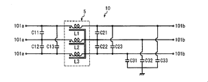
- the noise filter 10 is inserted between the power source 201, the inverter 202, and the electronic device 203.
- Fig. 10 shows the general configuration of the noise filter 10 for a three-phase power supply.
- interphase capacitors C11, C12, C13, C21, C22, C23 for reducing normal mode noise and common mode noise are connected between the input terminal 101a on the power supply side and the output terminal 101b on the electronic equipment side.
- a common mode choke coil 5 to be reduced and grounding capacitors C31, C32, and C33 are arranged.
- a choke coil for suppressing normal mode noise may be arranged in series with the power supply path.
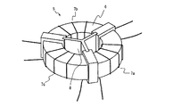
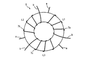
- FIG. 11 shows an example of the common mode choke coil 5.
- the common mode choke coil 5 includes, for example, an annular magnetic core 1 made of Mn-Zn ferrite, Fe-Si-B amorphous alloy, nanocrystalline soft magnetic alloy, or the like, as described in JP-A-2000-340437.
- a plurality of coils 7a, 7b, 7c wound around the annular magnetic core 1 are configured.
- the coil may be a bifilar winding.
- the common mode choke coil 5 exhibits a large impedance to the common mode noise flowing through the power supply path, attenuates the common mode noise from the power supply by the inductances of the coils 7a, 7b, and 7c and the ground capacitors C31, C32, and C33, Normal mode noise to the input terminal due to interphase capacitors C11, C12, C13 connected between each phase of the input terminal, interphase capacitors C21, C22, C23 connected between each phase of the output terminal, and leakage inductance of each coil The noise of the power source and the electronic device is prevented from entering each other.
- the noise regulation of VCCI standard or CISPR standard defines the limit of the noise terminal voltage in the frequency band of 150 kHz to 30 MHz.
- the saturation magnetic flux density of the magnetic material used in the magnetic core for common mode choke coils is important for suppressing high-voltage noise, and the magnetic material permeability and its frequency characteristics are important for widening the frequency band for noise reduction. is there.
- Japanese Patent Publication No. 7-74419 has a general formula: (Fe 1-a M a ) 100-XYZ- ⁇ Cu X Si Y B Z M ′ ⁇ (where M is Co and / or Ni, and M ′ is Nb , W, Ta, Zr, Hf, Ti, and Mo, at least one element selected from the group consisting of a, x, y, z, and ⁇ is 0 ⁇ a ⁇ 0.5, 0.1 ⁇ x ⁇ 3, 0 ⁇ y ⁇ 30, 0 ⁇ z ⁇ 25, 5 ⁇ y + z ⁇ 30 and 0.1 ⁇ ⁇ ⁇ 30), and at least 50% of the structure has an average particle size of 100 nm or less.
- An Fe-based soft magnetic alloy which is composed of fine crystal grains having a balance and is substantially amorphous. Although this Fe-based soft magnetic alloy has a high magnetic permeability even at high frequencies, it is likely to be magnetically saturated with a large current and may not function sufficiently as a choke coil. When the magnetic core is magnetically saturated by a large current, the magnetic permeability decreases and the inductance decreases. Therefore, when used in a noise filter, the attenuation performance of common mode noise and normal mode noise is low. If a magnetic gap is provided in the magnetic core in order to prevent a decrease in the damping performance, not only the magnetic core loss increases but also a problem of leakage magnetic flux in the magnetic gap occurs.
- Special Table 2006-525655 is made of a super microcrystalline alloy with a relative magnetic permeability ⁇ of 500-15000 and a saturation magnetostriction ⁇ of less than 15 ppm, and has high operating characteristics with a linear BH loop and AC and DC.
- a magnetic core having at least 50% of the ultrafine-crystalline alloy are occupied by the following microcrystal particles having an average particle size of 100 nm
- the ultrafine-crystalline alloy is the general formula: Fe a Co b Ni c Cu d M e Si f B g X h (where M is at least one of V, Nb, Ta, Ti, Mo, W, Zr, Cr, Mn and Hf, X is P, Ge, C and inevitable impurities)
- an object of the present invention is to provide an annular magnetic core that is less likely to be magnetically saturated with a large current and can maintain a high magnetic permeability, and a magnetic component such as a choke coil that can exhibit an excellent noise reduction effect.
- the annular magnetic core of the present invention is composed of a Fe-based nanocrystalline soft magnetic alloy in which a part of Fe is substituted with Ni and / or Co, AC relative permeability ⁇ r 100k (50) at a frequency of 100 kHz and a DC applied magnetic field strength of 50 A / m is 4000 or more, AC relative permeability ⁇ r 100k (150) at a frequency of 100 kHz and a DC applied magnetic field strength of 150 A / m is 2500 or more, The maximum permeability ⁇ Max at a DC applied magnetic field strength of 400 A / m is 8000 or less, and the magnetic flux density B 400 is 1.3 T or more.
- the annular magnetic core has an AC relative permeability ⁇ r 10k (150) of 4000 or more at a frequency of 10 kHz and a DC applied magnetic field strength of 150 A / m, and an AC ratio at a frequency of 10 kHz and DC applied magnetic field strength of 200 A / m.
- the permeability ⁇ r 10k (200) is preferably 2000 or more.
- the above-mentioned Fe-based nanocrystalline soft magnetic alloy has Fe and Ni and / or Co in total exceeding 75.5 atomic%, Ni and / or Co not exceeding 6 atomic%, Cu being 0.1 to 2 atomic%, and Nb being 0.1 to 4 atoms %, Si is contained in 8 to 12 atomic%, and B is preferably contained in 9 to 12 atomic%. More preferred compositions of Fe-based nanocrystalline soft magnetic alloys include Fe and Ni and / or Co totaling more than 75.5 atomic%, Ni and / or Co 4 to 6 atomic%, Si 10 to 11.5 atomic%, and B Is 9.2 to 10 atomic%.
- the Fe-based nanocrystalline soft magnetic alloy is preferably in the form of a ribbon having a thickness of 10 to 25 ⁇ m.
- the thickness of the ribbon is more preferably 14 to 25 ⁇ m.
- the magnetic component of the present invention is characterized in that the annular magnetic core is accommodated in a resin case, and a part of the annular magnetic core is fixed with an adhesive.
- a conductor passes through the hollow portion of the annular magnetic core.
- a conductor is wound around the annular magnetic core.
- the conductor is a conductor or a bus bar.
- the annular magnetic core of the present invention is less likely to be magnetically saturated and can maintain a high magnetic permeability even at a large current. Therefore, it is excellent in high voltage noise reduction performance and pulse attenuation characteristics, and is a small and lightweight choke filter that reduces noise in a wide frequency band. Is preferred.
- a magnetic gap required when using a high permeability Fe-based nanocrystalline soft magnetic alloy is not required, the number of processing steps can be reduced. Further, there is an advantage that the characteristic change due to magnetostriction is small as in the Fe-based amorphous alloy.
- FIG. 1 is a perspective view showing an example (Example 1) of an annular magnetic core of the present invention.
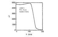
- 2 is a graph showing a direct current B-H loop of an annular magnetic core of Example 1.
- FIG. 6 is a graph showing the relationship between the AC relative permeability ⁇ r of the annular magnetic core of Example 1 and the magnetic field strength.
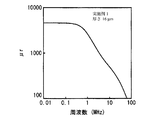
- 3 is a graph showing frequency characteristics of AC relative permeability ⁇ r of the annular magnetic core of Example 1.
- 6 is a graph showing frequency characteristics of impedance of a choke coil of Example 2.
- 3 is a graph showing direct current superimposed inductance characteristics of choke coils of Example 2 and Comparative Example 1. It is a perspective view which shows an example of a three-phase common mode choke coil.
- FIG. 6 is a graph showing frequency characteristics of impedance and inductance of a three-phase common mode choke coil of Example 3. It is a block diagram which shows the circuit which has arrange
- Fe and Ni and / or Co Fe is an element that largely controls the saturation magnetic flux density Bs.
- the total of Fe, Ni and / or Co is preferably more than 75.5 atomic%.
- the induced magnetic anisotropy can be increased, so that the relative permeability is intentionally reduced without significantly reducing the saturation magnetic flux density by heat treatment in a magnetic field. Therefore, it is possible to impart a characteristic that the magnetic saturation is difficult with respect to a large current.
- the core loss Pcv can be reduced by adding Ni and / or Co.
- the content of Ni and / or Co is preferably 6 atomic% or less.
- the magnetic permeability decreases greatly, the AC relative permeability ⁇ r 100k (50) at a frequency of 100 kHz and a DC applied magnetic field strength of 50 A / m is set to 4000 or more, and a frequency of 100 It is difficult to make the AC relative permeability ⁇ r 100k (150) at 2500 and above with a DC applied magnetic field strength of 150 A / m 2500 or more. Therefore, the number of windings must be increased in order to obtain a required impedance, which is not suitable for a choke coil.
- the magnetic permeability is obtained by applying a magnetic field perpendicular to the magnetic path direction of the magnetic core (alloy width direction) during the heat treatment.
- Ni lowers the saturation magnetic flux density Bs, when it is added alone, it becomes difficult to make the magnetic flux density B 400 1.3 T or more if the content exceeds 6 atomic%.
- the effect of inclining the BH curve is greater than that of Co in the range of 6 atomic% or less, the amount added can be reduced compared to Co.
- ⁇ Co slightly increases the saturation magnetic flux density Bs, but it is more expensive than Ni, so there is a problem of increased cost.
- Use in combination with Ni is preferable because it can suppress a decrease in the saturation magnetic flux density Bs depending on the proportion of Co.
- Cu is an element necessary for the precipitation of fine crystal grains by heat treatment.
- the Cu content is less than 0.1 atomic%, it is difficult to make 50 volume% or more of the alloy structure into fine crystal grains having an average crystal grain size of 100 ⁇ m or less.
- the Cu content exceeds 2 atomic%, the amorphous alloy ribbon before heat treatment is brittle, and winding and punching are difficult. Accordingly, the Cu content is preferably 0.1 to 2 atomic%. A more preferable Cu content is 0.5 to 1.5 atomic%.
- Nb contributes to the precipitation of fine crystal grains together with Cu. If Nb is less than 0.1 atomic%, the above effect cannot be obtained sufficiently. On the other hand, even if Nb exceeds 4 atomic%, there is no significant change in the effect of precipitating fine crystal grains, but the content of other metal elements may be reduced by that amount, which may deteriorate magnetic properties. . Therefore, the Nb content is preferably 0.1 to 4 atomic%. A more preferable Nb content is 1 to 3.5 atomic%. Note that a part or all of Nb may be replaced with an element (Ti, Zr, Hf, Mo, W, or Ta) having the same action.
- an element Ti, Zr, Hf, Mo, W, or Ta
- Both Si and B are amorphous phase forming elements.
- Si is 8 atomic% or more, an amorphous phase can be stably formed by rapid cooling, and the coercive force Hc and the core loss Pcv are reduced.
- the Si content exceeds 12 atomic%, the saturation magnetic flux density Bs decreases.
- the induced magnetic anisotropy is affected by the amount of Si in the Fe grains with bcc structure. Accordingly, the Si content is preferably 8 to 12 atomic%. A more preferable Si content is 10 to 11.5 atomic%.
- the B content is 9 atomic% or more, an amorphous phase can be stably formed by rapid cooling, and a uniform nanocrystalline phase can be obtained after heat treatment.
- the B content exceeds 12 atomic%, the saturation magnetic flux density Bs decreases. Therefore, the B content is preferably 9 to 12 atomic%.
- the B content is more preferably 9.2 to 10 atomic%.
- the total amount of Si and B is preferably 22 atomic percent or less, more preferably 21 atomic percent or less.
- the thickness of the Fe-based nanocrystalline soft magnetic alloy ribbon is preferably 10 to 25 ⁇ m. If the thickness is less than 10 ⁇ m, the mechanical strength of the ribbon is insufficient, and not only is it easy to break during handling, but also the coercive force Hc is increased. On the other hand, if the thickness exceeds 25 ⁇ m, it is difficult to stably obtain an amorphous state, and eddy current loss increases. When eddy current loss is not taken into consideration, the thickness of the ribbon is preferably 14 to 25 ⁇ m.
- FIG. 1 shows an example of an annular magnetic core 1 formed by winding an Fe-based nanocrystalline soft magnetic alloy ribbon 100 of the present invention.
- a magnetic core obtained by punching a ribbon into a donut shape and laminating a plurality of sheets may be used.
- the annular magnetic core 1 is not limited to a circular shape, and may be a racetrack shape, a rectangular shape, or the like.
- the obtained annular magnetic core is heat-treated at a temperature equal to or higher than the crystallization start temperature for 10 minutes or more in an inert gas atmosphere such as nitrogen gas or in the air while applying a magnetic field.
- An annular magnetic core made of an Fe-based nanocrystalline soft magnetic alloy is obtained in which 50% by volume or more of the alloy structure is occupied by fine crystal grains of bcc structure having an average crystal grain size of 100 nm or less.
- the temperature at which the bcc structure Fe crystal grains precipitate is about 480 to 560 ° C.
- the crystallization start temperature is an exothermic start temperature obtained by differential scanning calorimetry. When a compound phase such as Fe 2 B precipitates, the coercive force Hc increases and the constant magnetic permeability is lost. Therefore, the upper limit of the heat treatment temperature is preferably set to a temperature at which the compound phase does not precipitate.
- the holding time is important as well as the temperature. Since the induced magnetic anisotropy is affected by the amount of Si in the Fe crystal grains of the bcc structure, it is necessary to sufficiently dissolve Si in Fe during crystallization. Therefore, the maximum temperature holding time is preferably 10 minutes or longer. If the heat treatment temperature is lowered, the holding time becomes longer, but the upper limit is preferably 60 minutes in consideration of productivity.
- the heat treatment in a magnetic field itself is a known method as disclosed in, for example, Japanese Patent Publication No. 7-74419.
- the applied magnetic field is preferably at least 1000 A / m or more in order to saturate the alloy.
- the solid solution of Si is insufficient and the anisotropy is not induced, but as the solid solution of Si advances, the induction of anisotropy proceeds rapidly. Therefore, it is preferable to apply the magnetic field from a temperature lower than the crystallization temperature.
- the rate of temperature rise from the start of application of the magnetic field to the holding temperature is 5 ° C./min or less. If the rate of temperature increase is too fast, crystallization is completed quickly due to heat generated by crystallization. Although anisotropy can be induced even after crystallization, it is insufficient compared to the anisotropy obtained during crystallization. Further, crystallization may be completed in a state where the solid solution of Si is insufficient. In order to obtain sufficient induction of anisotropy, the rate of temperature rise is more preferably less than 1 ° C./min.
- the AC relative permeability ⁇ r is a permeability obtained by the following equation (1) from the effective self-inductance of a coil having a closed magnetic path magnetic core in which leakage flux can be ignored.
- ⁇ r (L ⁇ C1) / ( ⁇ 0 ⁇ N 2 ) ...
- L Effective self-inductance (H)
- N Total number of turns
- ⁇ 0 Vacuum permeability (4 ⁇ ⁇ ⁇ 10 -7 )
- C1 Magnetic constant (mm -1 )
- the effective self-inductance L was measured with an LCR meter (Agilent Technologies, Inc. 4284A) and an impedance / gain phase analyzer (Agilent Technologies, Inc. 4194A).
- the relationship between the magnetic field and the relative permeability ⁇ r is measured using a measuring device that can superimpose a DC current of up to 20 A in combination with an LCR meter 4284A and a bias current source (42841A made by Agilent Technologies, Inc.). It was determined by measuring the superimposed inductance.
- the AC relative permeability ⁇ r was obtained from the effective self-inductance L at a predetermined frequency (for example, 100 kHz) by the above formula (1).
- the bias current I for generating a predetermined DC applied magnetic field strength H (for example, 50 A / m) was obtained by the following equation (2).
- H I ⁇ N / Le (2)
- H DC applied magnetic field strength (A / m)
- I Bias current (A)
- N Total number of turns
- Le Average track length (m)
- the frequency characteristic of the AC relative permeability ⁇ r was measured using an impedance / gain phase analyzer 4194A at an operating magnetic field of 0.05 A / m and a frequency of 10 kHz to 10 MHz.
- the maximum permeability ⁇ Max , the magnetic flux density B 400 and the coercive force Hc at a DC applied magnetic field strength of 400 A / m were measured together with a DC magnetization characteristic test apparatus (SK-110 model manufactured by Metron Engineering Co., Ltd.).
- AC relative permeability ⁇ r 100k (50) and ⁇ r 100k (150) at a DC applied magnetic field strength of 50 A / m and 150 A / m at a frequency of 100 kHz respectively. It is specified as 4000 or more and 2500 or more. If the AC relative permeability ⁇ r 100k (50) is 4000 or more and the AC relative permeability ⁇ r 100k (150) is 2500 or more, the decrease in the attenuation performance of common mode noise and normal mode noise due to the decrease in permeability is suppressed. And exhibits an excellent noise suppression effect.
- AC relative permeability .mu.r 10k at 10 kHz frequency and the applied DC magnetic field intensity 150 A / m (150) is not less than 4,000, and the AC relative permeability .mu.r 10k at 10 kHz frequency and the applied DC magnetic field strength 200 A / m (200) is more preferably 2000 or more.
- the Fe-based nanocrystalline soft magnetic alloy used for the annular magnetic core of the present invention maintains the characteristic that a relatively higher magnetic permeability than other magnetic materials can be obtained even at high frequencies.
- the noise filter using the magnetic component is also excellent in reducing noise in a wide frequency band as well as reducing high-voltage noise.
- FIG. 11 shows a three-phase common mode choke coil having a configuration in which three conductors a, b, and c are passed through an annular magnetic core 5 ′ as an example of a magnetic component that penetrates a conductor through a hollow portion of the annular magnetic core.
- FIG. 11 (b) shows a three-phase common mode choke coil in which three conductors a, b, and c are wound around an annular magnetic core 5 ′ as an example of a magnetic component in which a conductor is wound around an annular magnetic core.
- FIG. 12 shows a state in which the annular magnetic core 5 ′ is put into an insulating core case composed of the upper case 11 and thus the case 12.
- Example 1 By a single roll method, a molten metal having a composition of Fe 70.7 Ni 5.0 Cu 0.8 Nb 2.8 Si 10.9 B 9.8 (atomic%) is jetted onto the surface of a copper roll rotating at a high speed from a nozzle and rapidly cooled to a thickness of 16 ⁇ m. An alloy ribbon having a width of 53 mm was obtained at 18 ⁇ m and 23 ⁇ m. X-ray diffraction measurement confirmed that the structure of these alloy ribbons was substantially amorphous. The crystallization temperature Tx of this alloy determined by differential scanning calorimetry was 490 ° C.
- Each slit was slit and two strips with a width of 25 mm were obtained.
- Each thin ribbon was wound to obtain an annular wound core (space factor: 0.9) having an outer diameter of 24.5 mm, an inner diameter of 21 mm, and a height width of 25 mm.
- An annular core is placed in a heat treatment furnace controlled in a nitrogen atmosphere, the temperature is raised from 420 ° C to the maximum temperature of 550 ° C at a rate of 0.54 ° C / min, held at the maximum temperature for 20 minutes, and then cooled in the furnace As a result, an annular wound core made of the Fe-based nanocrystalline soft magnetic alloy shown in FIG. 1 was obtained.
- FIG. 2 shows a DC BH loop of an annular magnetic core using a ribbon having a thickness of 16 ⁇ m as a representative example.
- each annular magnetic core in an insulating case apply 10 turns of winding, and change the AC ratio to the strength of 50 A / m, 150 A / m and 200 A / m of DC applied magnetic field with frequency of 10 kHz and 100 kHz at 25 ° C.
- the relationship of magnetic permeability ⁇ r was obtained by LCR meter 4284A.
- each annular magnetic core (sample No. 1-5) in an insulating case, wind 1 turn, and use an impedance / gain phase analyzer 4194A for voltage amplitude 0.5 Vrms, frequency 10-100 kHz, temperature 25 ° C AC
- the relative magnetic permeability ⁇ r 10k and ⁇ r 100k were measured. Further, the frequency f50 at which the relative permeability ⁇ r of 50% of the relative permeability ⁇ r10k at the frequency of 10 kHz was obtained was obtained.
- the results are shown in Table 1.
- FIG. 4 shows the frequency characteristics of the relative permeability ⁇ r using a ribbon having a thickness of 16 ⁇ m.
- the annular magnetic core of the present invention has a small squareness ratio and excellent constant permeability while maintaining a high magnetic flux density, and a small change in AC relative permeability with respect to frequency.
- Both are 4000 or more
- AC relative permeability ⁇ r 100k (150) at frequency 100 kHz and DC applied magnetic field strength 150 A / m is 2500 or more
- the AC relative permeability ⁇ r 10k (200) is 2000 or more.
- the annular magnetic core of the present invention has a high AC relative permeability from a low magnetic field region to a high magnetic field region. Furthermore, it can be seen that an annular magnetic core using a thin ribbon has little reduction in AC relative permeability and is excellent in frequency characteristics.
- Comparative Example 1 An annular core with an outer diameter of 36.0 mm, an inner diameter of 17.5 mm, and a height of 25 mm was prepared using a thin ribbon (thickness 18 ⁇ m) of Fe-based nanocrystalline soft magnetic alloy FT-3KL (manufactured by Hitachi Metals, Ltd.). This was put into a case, and a choke coil was manufactured by winding an enameled wire with a wire diameter of 2.5 mm for 8 turns.
- Example 2 An annular core having an outer diameter of 36.0 mm, an inner diameter of 17.5 mm, and a height width of 25 mm was produced using the ribbon (thickness 18 ⁇ m) produced in Example 1, and this was put in a case, and the wire diameter was 2.5 mm.
- a choke coil was made by winding 17 turns of enameled wire.
- Fig. 5 shows the impedance of the choke coil. As is apparent from FIG. 5, the choke coil of Example 2 exhibited excellent impedance performance from the low frequency range to the high frequency range.
- Example 3 The three-phase common mode choke coil shown in FIG. 7 is formed using an annular core having an outer diameter of 17.8 mm, an inner diameter of 13.8 mm, and a height of 25 mm using the ribbon (thickness: 18 ⁇ m) produced in Example 1. Produced.
- the annular magnetic core was placed in an insulating case 6, and a partition plate 8 for partitioning a winding region was provided at the center of the case.
- the windings 7a, 7b, and 7c for each phase were formed by winding an enameled wire with a wire diameter of 2.5 mm for three turns.
- Figure 8 shows the frequency characteristics of impedance and inductance of the three-phase common mode choke coil. In the figure, a solid line indicates inductance, and a broken line indicates impedance. As is apparent from FIG. 8, the three-phase common mode choke coil of Example 3 exhibited excellent impedance performance from a low frequency range to a high frequency range.
- Example 4 A noise filter shown in FIG. 9 was produced using the three-phase common mode choke coil obtained in Example 2.
- the obtained noise filter was excellent in the attenuation of low frequency noise, high frequency noise, and pulse noise, and was excellent in the effect of reducing the noise terminal voltage in a wide frequency band of 150 kHz to 30 MHz.
- Example 5 In the same manner as in Example 1, an alloy ribbon having a thickness of 16 ⁇ m and a width of 53 mm was prepared from each molten metal having the composition (atomic%) shown in Table 2. Each strip was slit and two strips with a width of 25 mm were obtained. Each thin ribbon was wound to obtain an annular core (space factor: 0.9) having an outer diameter of 24.5 mm, an inner diameter of 21 mm, and a height width of 25 mm. Each of the annular cores was heat-treated in the same magnetic field as in Example 1 to obtain an annular core composed of an Fe-based nanocrystalline soft magnetic alloy.
Landscapes
- Chemical & Material Sciences (AREA)
- Engineering & Computer Science (AREA)
- Materials Engineering (AREA)
- Mechanical Engineering (AREA)
- Metallurgy (AREA)
- Organic Chemistry (AREA)
- Crystallography & Structural Chemistry (AREA)
- Physics & Mathematics (AREA)
- Thermal Sciences (AREA)
- Power Engineering (AREA)
- Inorganic Chemistry (AREA)
- Electromagnetism (AREA)
- Dispersion Chemistry (AREA)
- Soft Magnetic Materials (AREA)
- Coils Or Transformers For Communication (AREA)
Abstract
Priority Applications (4)
| Application Number | Priority Date | Filing Date | Title |
|---|---|---|---|
| ES14751452T ES2775211T3 (es) | 2013-02-15 | 2014-02-14 | Método de producción de un núcleo magnético anular realizado con aleación magnética blanda, nanocristalina, basada en Fe, y método de producción de un dispositivo magnético que comprende el mismo |
| CN201480008901.3A CN105074843B (zh) | 2013-02-15 | 2014-02-14 | 使用了Fe基纳米晶体软磁性合金的环状磁芯、以及使用其的磁性部件 |
| EP14751452.5A EP2958116B1 (fr) | 2013-02-15 | 2014-02-14 | Procédé de fabrication d'un noyau magnétique annulaire utilisant un alliage magnétique doux nanocristallin à base de fer |
| JP2015500319A JP6075438B2 (ja) | 2013-02-15 | 2014-02-14 | Fe基ナノ結晶軟磁性合金を用いた環状磁心、及びそれを用いた磁性部品 |
Applications Claiming Priority (2)
| Application Number | Priority Date | Filing Date | Title |
|---|---|---|---|
| JP2013027500 | 2013-02-15 | ||
| JP2013-027500 | 2013-02-15 |
Publications (1)
| Publication Number | Publication Date |
|---|---|
| WO2014126220A1 true WO2014126220A1 (fr) | 2014-08-21 |
Family
ID=51354218
Family Applications (1)
| Application Number | Title | Priority Date | Filing Date |
|---|---|---|---|
| PCT/JP2014/053536 Ceased WO2014126220A1 (fr) | 2013-02-15 | 2014-02-14 | Noyau magnétique annulaire utilisant un alliage magnétique doux nanocristallin à base de fer et constituant magnétique utilisant ledit noyau magnétique annulaire |
Country Status (5)
| Country | Link |
|---|---|
| EP (1) | EP2958116B1 (fr) |
| JP (1) | JP6075438B2 (fr) |
| CN (1) | CN105074843B (fr) |
| ES (1) | ES2775211T3 (fr) |
| WO (1) | WO2014126220A1 (fr) |
Cited By (9)
| Publication number | Priority date | Publication date | Assignee | Title |
|---|---|---|---|---|
| JP2019125670A (ja) * | 2018-01-16 | 2019-07-25 | 日立金属株式会社 | 電子回路、及び、ノイズフィルタの設置方法 |
| JP2020503676A (ja) * | 2017-01-03 | 2020-01-30 | エルジー イノテック カンパニー リミテッド | インダクタ及びこれを含むemiフィルター |
| JP2022016456A (ja) * | 2016-06-14 | 2022-01-21 | 株式会社Fuji | 電気的特性取得装置 |
| JP2022515597A (ja) * | 2018-12-06 | 2022-02-21 | ボード オブ スーパーバイザーズ オブ ルイジアナ ステイト ユニバーシティ アンド アグリカルチュラル アンド メカニカル カレッジ | 磁性コアを使用して、高い均一性を備えたパルス電界を適用する方法およびシステム |
| CN114694908A (zh) * | 2022-05-30 | 2022-07-01 | 天津三环奥纳科技有限公司 | 一种耐低温纳米晶软磁合金铁芯、制造方法及应用 |
| JP2022124953A (ja) * | 2021-02-16 | 2022-08-26 | 株式会社リケン | ノイズ対策用環状磁性体及びノイズ対策用部材 |
| CN116313474A (zh) * | 2023-02-15 | 2023-06-23 | 安徽省昌盛电子有限公司 | 一种共模电感器的生产工艺 |
| CN116298464A (zh) * | 2023-02-27 | 2023-06-23 | 西北核技术研究所 | 组合磁芯式宽频电流传感器 |
| WO2024023999A1 (fr) * | 2022-07-27 | 2024-02-01 | 株式会社リケン | Corps magnétique annulaire à des fins de gestion du bruit et élément de gestion du bruit |
Families Citing this family (7)
| Publication number | Priority date | Publication date | Assignee | Title |
|---|---|---|---|---|
| JP6490313B2 (ja) | 2016-12-07 | 2019-03-27 | パナソニック株式会社 | 鉄心及びモータ |
| CN110352464B (zh) * | 2017-02-22 | 2021-02-19 | 日立金属株式会社 | 磁芯单元、电流互感器和它们的制造方法 |
| WO2019031462A1 (fr) * | 2017-08-07 | 2019-02-14 | 日立金属株式会社 | Poudre d'alliage nanocristallin à base de fe, son procédé de production, poudre d'alliage amorphe à base de fe et noyau magnétique |
| CN109295401A (zh) * | 2018-12-11 | 2019-02-01 | 广东工业大学 | 一种新型铁基非晶纳米晶软磁合金及其制备方法 |
| CN109797344A (zh) * | 2019-01-25 | 2019-05-24 | 上海电力学院 | 一种Fe基软磁合金及软磁合金带材制备方法 |
| JP6860716B1 (ja) * | 2020-02-05 | 2021-04-21 | 株式会社リケン | ノイズ対策用環状磁性体 |
| CN121237528A (zh) * | 2025-12-01 | 2025-12-30 | 中国科学院宁波材料技术与工程研究所 | 一种非晶纳米晶软磁合金粉末及其制备方法与磁粉芯 |
Citations (8)
| Publication number | Priority date | Publication date | Assignee | Title |
|---|---|---|---|---|
| JPS62167851A (ja) * | 1985-06-13 | 1987-07-24 | Hitachi Metals Ltd | 低損失Fe基非晶質合金 |
| JPS6479342A (en) * | 1986-12-15 | 1989-03-24 | Hitachi Metals Ltd | Fe-base soft magnetic alloy and its production |
| JPH0774419B2 (ja) | 1986-12-15 | 1995-08-09 | 日立金属株式会社 | Fe基軟磁性合金の製造方法 |
| JPH08153614A (ja) * | 1995-03-13 | 1996-06-11 | Hitachi Metals Ltd | 磁 心 |
| JP2000119821A (ja) * | 1998-10-15 | 2000-04-25 | Hitachi Metals Ltd | 恒透磁率性に優れた高飽和磁束密度低損失磁性合金ならびにそれを用いた磁性部品 |
| JP2000340437A (ja) | 1999-05-31 | 2000-12-08 | Toshiba Corp | ノイズフィルタ |
| JP2006525655A (ja) | 2003-04-02 | 2006-11-09 | バクームシュメルツェ ゲゼルシャフト ミット ベシュレンクテル ハフツング ウント コンパニ コマンディートゲゼルシャフト | 鉄心とその製造および使用方法 |
| WO2010084888A1 (fr) * | 2009-01-20 | 2010-07-29 | 日立金属株式会社 | Bande mince d'alliage magnétique tendre, procédé de production de ladite bande et composant magnétique comprenant la bande mince d'alliage magnétique tendre |
Family Cites Families (11)
| Publication number | Priority date | Publication date | Assignee | Title |
|---|---|---|---|---|
| JP2698369B2 (ja) * | 1988-03-23 | 1998-01-19 | 日立金属株式会社 | 低周波トランス用合金並びにこれを用いた低周波トランス |
| US5443664A (en) * | 1988-11-16 | 1995-08-22 | Hitachi Metals, Ltd. | Surge current-suppressing circuit and magnetic device therein |
| CN1092201A (zh) * | 1994-01-29 | 1994-09-14 | 冶金工业部钢铁研究总院 | 铁基快淬软磁合金铁芯的制造方法 |
| JP3891448B2 (ja) * | 1994-04-11 | 2007-03-14 | 日立金属株式会社 | 薄型アンテナおよびそれを用いたカード |
| JP2000100617A (ja) * | 1998-09-25 | 2000-04-07 | Masaaki Yagi | 磁心付きコイル及びpam制御エアコン |
| CN1905091A (zh) * | 2005-07-28 | 2007-01-31 | 黄付贵 | 一种纳米晶软磁铁芯及其热处理方法和应用 |
| CN101241790B (zh) * | 2007-11-16 | 2010-06-16 | 中国计量学院 | 软磁磁粉及其制造方法 |
| EP2416329B1 (fr) * | 2010-08-06 | 2016-04-06 | Vaccumschmelze Gmbh & Co. KG | Noyau magnétique pour des applications basse fréquence et procédé de fabrication d'un noyau magnétique pour des applications basse fréquence |
| US9773595B2 (en) * | 2011-04-15 | 2017-09-26 | Vacuumschmelze Gmbh & Co. Kg | Alloy, magnetic core and process for the production of a tape from an alloy |
| DE102011002114A1 (de) * | 2011-04-15 | 2012-10-18 | Vacuumschmelze Gmbh & Co. Kg | Legierung, Magnetkern und Verfahren zum Herstellen eines Bandes aus einer Legierung |
| JP6003899B2 (ja) * | 2011-10-06 | 2016-10-05 | 日立金属株式会社 | Fe基初期超微結晶合金薄帯及び磁性部品 |
-
2014
- 2014-02-14 ES ES14751452T patent/ES2775211T3/es active Active
- 2014-02-14 EP EP14751452.5A patent/EP2958116B1/fr active Active
- 2014-02-14 CN CN201480008901.3A patent/CN105074843B/zh active Active
- 2014-02-14 WO PCT/JP2014/053536 patent/WO2014126220A1/fr not_active Ceased
- 2014-02-14 JP JP2015500319A patent/JP6075438B2/ja active Active
Patent Citations (8)
| Publication number | Priority date | Publication date | Assignee | Title |
|---|---|---|---|---|
| JPS62167851A (ja) * | 1985-06-13 | 1987-07-24 | Hitachi Metals Ltd | 低損失Fe基非晶質合金 |
| JPS6479342A (en) * | 1986-12-15 | 1989-03-24 | Hitachi Metals Ltd | Fe-base soft magnetic alloy and its production |
| JPH0774419B2 (ja) | 1986-12-15 | 1995-08-09 | 日立金属株式会社 | Fe基軟磁性合金の製造方法 |
| JPH08153614A (ja) * | 1995-03-13 | 1996-06-11 | Hitachi Metals Ltd | 磁 心 |
| JP2000119821A (ja) * | 1998-10-15 | 2000-04-25 | Hitachi Metals Ltd | 恒透磁率性に優れた高飽和磁束密度低損失磁性合金ならびにそれを用いた磁性部品 |
| JP2000340437A (ja) | 1999-05-31 | 2000-12-08 | Toshiba Corp | ノイズフィルタ |
| JP2006525655A (ja) | 2003-04-02 | 2006-11-09 | バクームシュメルツェ ゲゼルシャフト ミット ベシュレンクテル ハフツング ウント コンパニ コマンディートゲゼルシャフト | 鉄心とその製造および使用方法 |
| WO2010084888A1 (fr) * | 2009-01-20 | 2010-07-29 | 日立金属株式会社 | Bande mince d'alliage magnétique tendre, procédé de production de ladite bande et composant magnétique comprenant la bande mince d'alliage magnétique tendre |
Cited By (22)
| Publication number | Priority date | Publication date | Assignee | Title |
|---|---|---|---|---|
| JP2022016456A (ja) * | 2016-06-14 | 2022-01-21 | 株式会社Fuji | 電気的特性取得装置 |
| JP7223825B2 (ja) | 2016-06-14 | 2023-02-16 | 株式会社Fuji | 電気的特性取得装置 |
| JP2022174101A (ja) * | 2017-01-03 | 2022-11-22 | エルジー イノテック カンパニー リミテッド | インダクタ及びこれを含むemiフィルター |
| JP2020503676A (ja) * | 2017-01-03 | 2020-01-30 | エルジー イノテック カンパニー リミテッド | インダクタ及びこれを含むemiフィルター |
| US12482586B2 (en) | 2017-01-03 | 2025-11-25 | Lg Innotek Co., Ltd. | Inductor and EMI filter including the same |
| US11289252B2 (en) | 2017-01-03 | 2022-03-29 | Lg Innotek Co., Ltd. | Inductor and EMI filter including the same |
| US11955262B2 (en) | 2017-01-03 | 2024-04-09 | Lg Innotek Co., Ltd. | Inductor and EMI filter including the same |
| JP7345026B2 (ja) | 2017-01-03 | 2023-09-14 | エルジー イノテック カンパニー リミテッド | インダクタ及びこれを含むemiフィルター |
| JP7130645B2 (ja) | 2017-01-03 | 2022-09-05 | エルジー イノテック カンパニー リミテッド | インダクタ及びこれを含むemiフィルター |
| JP7082753B2 (ja) | 2018-01-16 | 2022-06-09 | 日立金属株式会社 | 電子回路、及び、ノイズフィルタの設置方法 |
| JP2019125670A (ja) * | 2018-01-16 | 2019-07-25 | 日立金属株式会社 | 電子回路、及び、ノイズフィルタの設置方法 |
| JP7592250B2 (ja) | 2018-12-06 | 2024-12-02 | ボード オブ スーパーバイザーズ オブ ルイジアナ ステイト ユニバーシティ アンド アグリカルチュラル アンド メカニカル カレッジ | 磁性コアを使用して、高い均一性を備えたパルス電界を適用する方法およびシステム |
| JP2022515597A (ja) * | 2018-12-06 | 2022-02-21 | ボード オブ スーパーバイザーズ オブ ルイジアナ ステイト ユニバーシティ アンド アグリカルチュラル アンド メカニカル カレッジ | 磁性コアを使用して、高い均一性を備えたパルス電界を適用する方法およびシステム |
| JP2022124953A (ja) * | 2021-02-16 | 2022-08-26 | 株式会社リケン | ノイズ対策用環状磁性体及びノイズ対策用部材 |
| JP7454518B2 (ja) | 2021-02-16 | 2024-03-22 | 株式会社リケン | ノイズ対策用環状磁性体及びノイズ対策用部材 |
| CN114694908A (zh) * | 2022-05-30 | 2022-07-01 | 天津三环奥纳科技有限公司 | 一种耐低温纳米晶软磁合金铁芯、制造方法及应用 |
| CN114694908B (zh) * | 2022-05-30 | 2023-11-24 | 天津三环奥纳科技有限公司 | 一种耐低温纳米晶软磁合金铁芯、制造方法及应用 |
| WO2024023999A1 (fr) * | 2022-07-27 | 2024-02-01 | 株式会社リケン | Corps magnétique annulaire à des fins de gestion du bruit et élément de gestion du bruit |
| US12476030B2 (en) | 2022-07-27 | 2025-11-18 | Kabushiki Kaisha Riken | Annular magnetic body for noise control and member for noise control |
| CN116313474A (zh) * | 2023-02-15 | 2023-06-23 | 安徽省昌盛电子有限公司 | 一种共模电感器的生产工艺 |
| CN116298464A (zh) * | 2023-02-27 | 2023-06-23 | 西北核技术研究所 | 组合磁芯式宽频电流传感器 |
| CN116298464B (zh) * | 2023-02-27 | 2025-09-19 | 西北核技术研究所 | 组合磁芯式宽频电流传感器 |
Also Published As
| Publication number | Publication date |
|---|---|
| EP2958116B1 (fr) | 2020-01-01 |
| EP2958116A1 (fr) | 2015-12-23 |
| JPWO2014126220A1 (ja) | 2017-02-02 |
| CN105074843B (zh) | 2018-06-08 |
| ES2775211T3 (es) | 2020-07-24 |
| EP2958116A4 (fr) | 2016-10-12 |
| JP6075438B2 (ja) | 2017-02-08 |
| CN105074843A (zh) | 2015-11-18 |
Similar Documents
| Publication | Publication Date | Title |
|---|---|---|
| JP6075438B2 (ja) | Fe基ナノ結晶軟磁性合金を用いた環状磁心、及びそれを用いた磁性部品 | |
| JP5664934B2 (ja) | 軟磁性合金およびこれを用いた磁性部品 | |
| CN109716463B (zh) | 纳米晶合金磁芯、磁芯组件和纳米晶合金磁芯的制造方法 | |
| JP3233313B2 (ja) | パルス減衰特性に優れたナノ結晶合金の製造方法 | |
| JP4210986B2 (ja) | 磁性合金ならびにそれを用いた磁性部品 | |
| JP2008109080A (ja) | 圧粉磁心及びその製造方法 | |
| CN107464649B (zh) | 一种具有线性磁滞回线的磁芯 | |
| JP3719449B2 (ja) | ナノ結晶合金およびその製造方法ならびにそれを用いた磁心 | |
| JP5445891B2 (ja) | 軟磁性薄帯、磁心、および磁性部品 | |
| JP6860716B1 (ja) | ノイズ対策用環状磁性体 | |
| JP2007270271A (ja) | 軟磁性合金、その製造方法ならびに磁性部品 | |
| JP4547671B2 (ja) | 高飽和磁束密度低損失磁性合金ならびにそれを用いた磁性部品 | |
| JP7082753B2 (ja) | 電子回路、及び、ノイズフィルタの設置方法 | |
| JP2008235525A (ja) | リアクトル磁心およびリアクトル | |
| JP4310738B2 (ja) | 軟磁性合金並びに磁性部品 | |
| JPH0468382B2 (fr) | ||
| JP2009293132A (ja) | 軟磁性薄帯、磁心、磁性部品、および軟磁性薄帯の製造方法 | |
| JP4003166B2 (ja) | Co基磁性合金ならびにそれを用いた磁性部品 | |
| JPH08115830A (ja) | ライン・ノイズ・フィルタ | |
| JP2002164208A (ja) | 圧粉磁芯用粉末、圧粉磁芯およびその製造方法、およびそれを用いた高周波リアクトル | |
| JPH0927413A (ja) | チョークコイル用磁心およびその製造方法 | |
| JP3638291B2 (ja) | 低損失磁心 | |
| JPH04348006A (ja) | ノイズフィルタ | |
| KR20170053480A (ko) | 연자성 합금 | |
| JP2026061949A (ja) | ナノ結晶合金薄帯 |
Legal Events
| Date | Code | Title | Description |
|---|---|---|---|
| WWE | Wipo information: entry into national phase |
Ref document number: 201480008901.3 Country of ref document: CN |
|
| 121 | Ep: the epo has been informed by wipo that ep was designated in this application |
Ref document number: 14751452 Country of ref document: EP Kind code of ref document: A1 |
|
| ENP | Entry into the national phase |
Ref document number: 2015500319 Country of ref document: JP Kind code of ref document: A |
|
| NENP | Non-entry into the national phase |
Ref country code: DE |
|
| WWE | Wipo information: entry into national phase |
Ref document number: 2014751452 Country of ref document: EP |