WO2014128982A1 - 把持装置 - Google Patents
把持装置 Download PDFInfo
- Publication number
- WO2014128982A1 WO2014128982A1 PCT/JP2013/060927 JP2013060927W WO2014128982A1 WO 2014128982 A1 WO2014128982 A1 WO 2014128982A1 JP 2013060927 W JP2013060927 W JP 2013060927W WO 2014128982 A1 WO2014128982 A1 WO 2014128982A1
- Authority
- WO
- WIPO (PCT)
- Prior art keywords
- bag
- light emitting
- inner bag
- workpiece
- outer bag
- Prior art date
- Legal status (The legal status is an assumption and is not a legal conclusion. Google has not performed a legal analysis and makes no representation as to the accuracy of the status listed.)
- Ceased
Links
Images



Classifications
-
- B—PERFORMING OPERATIONS; TRANSPORTING
- B25—HAND TOOLS; PORTABLE POWER-DRIVEN TOOLS; MANIPULATORS
- B25J—MANIPULATORS; CHAMBERS PROVIDED WITH MANIPULATION DEVICES
- B25J19/00—Accessories fitted to manipulators, e.g. for monitoring, for viewing; Safety devices combined with or specially adapted for use in connection with manipulators
- B25J19/02—Sensing devices
- B25J19/021—Optical sensing devices
-
- B—PERFORMING OPERATIONS; TRANSPORTING
- B25—HAND TOOLS; PORTABLE POWER-DRIVEN TOOLS; MANIPULATORS
- B25J—MANIPULATORS; CHAMBERS PROVIDED WITH MANIPULATION DEVICES
- B25J15/00—Gripping heads and other end effectors
- B25J15/0023—Gripper surfaces directly activated by a fluid
Definitions
- the present invention relates to a gripping device.
- Japanese Patent Application Laid-Open No. 2011-230260 includes an abutment member having an inner bag filled with a granular material and an outer bag covering the inner bag at the tip of a gripping portion of the gripping device, and the corresponding contact member is an outer shape of a workpiece.
- a technique is disclosed in which, after being deformed along the shape, the air is cured while the shape is maintained by removing air from the inner bag.
- durability is improved by creating the outer bag with a woven fabric made of aramid fibers.
- the gripping device may be used for a purpose of gripping a workpiece to which oil, chips, or the like adheres, such as mechanical parts, and dirt may adhere to the outer bag. In such a state, it is difficult to visually confirm whether or not the outer bag is damaged.
- the gripping device of the present invention is a gripping device having a gripping part that grips and holds a work, and includes a contact member attached to a part of the gripping part that comes into contact with the work.
- An inner bag made of a material having elasticity, a granular material filled in the inner bag, an outer bag covering the inner bag, and with respect to the inner volume of the inner bag in a state where the workpiece is gripped by the grip portion
- the granular material hardens while deforming into a shape along the outer surface shape of the workpiece, and a light emitting portion is provided between the back surface of the outer bag and the surface of the inner bag.
- the light emitting part is provided on at least one of the back surface of the outer bag and the front surface of the inner bag.
- the light emitting part emits light in response to ultraviolet light.
- the light emitting unit is constituted by a phosphorescent member.
- the image of the torn part when the outer bag is torn, the image of the torn part can be revealed in the dark place by the light emitting part, and can be easily observed. Thereby, it is possible to detect breakage that has occurred in the outer bag without being affected by dirt on the outer bag, and to prevent damage to the inner bag.
- FIG. 1 It is a figure which shows a holding
- the gripping device 1 is a device for gripping and holding a workpiece or the like, and includes a gripping portion 2, a control device 7, and a vacuum exhaust equipment 8, as shown in FIG.
- the grip part 2 is a part for directly gripping a workpiece, and includes a drive part 3, a plurality of claw parts 4 and 5, and a plurality of contact members 6.
- the drive unit 3 includes two systems of slider units 3a and 3b, and each slider unit 3a and 3b is independently reciprocally displaced in the same axial direction. Can do.
- an electric actuator including a reciprocating mechanism including a ball screw / nut and a motor can be employed.
- claw parts 4 and 5 are a pair of site
- claw part 4 * 5 clamps and hold
- the shapes of the claw portions 4 and 5 are set in consideration of the shape and size of the workpiece to be grasped, the stroke amount of the slider portions 3a and 3b, and the like.
- the claw portion 4 includes a support portion 4a and two clamping portions 4b and 4b that protrude from the support portion 4a.
- the clamping parts 4b and 4b are arranged at a predetermined interval from each other.
- the claw portion 4 has a surface on the side where the contact member 6 is provided as an attachment surface 4g.
- support part 4a is being fixed to slider part 3a.
- the drive part 3 is operated by the control apparatus 7, the slider part 3a is slid, and each clamping part 4b * 4b is reciprocated along the sliding direction of the slider part 3a (refer FIG. 1).
- the claw portion 5 includes a support portion 5a and one pressing portion 5b protruding from the support portion 5a. Moreover, the nail
- support part 5a is being fixed to slider part 3b. And the drive part 3 is operated by the control apparatus 7, the slider part 3b is slid, and the clamping part 5b is reciprocated along the sliding direction of the slider part 3b (refer FIG. 1).
- the abutting member 6 is a part that directly abuts on the workpiece in the gripping device 1, and realizes two contradictory modes, a mode in which the shape can be flexibly deformed and a mode in which the shape is firmly held, with a single member. To do. In the regular state, it has a mode that can be flexibly deformed.
- the abutting member 6 is attached to the clamping portions 4 b, 4 b, and 5 b of the claw portions 4 and 5, respectively, and is connected to the vacuum exhaust equipment 8.
- the vacuum evacuation equipment 8 constitutes a means for hardening and softening the contact member 6, and includes a vacuum pump 8a, vacuum pipes 8b and 8b, and an electromagnetic valve 8c. And each vacuum piping 8b * 8b is connected to the bag-shaped part of each contact member 6.
- FIG. In the present embodiment, the case where the vacuum pump 8a is provided in the vacuum exhaust equipment 8 is illustrated, but a configuration including exhaust means (for example, an ejector) other than the vacuum pump 8a is also possible.
- the means for realizing the hardening and softening of the contact member does not necessarily need to be an evacuation facility, and a means capable of realizing the hardening and softening of the contact member can be adopted.
- the abutting member 6 When the abutting member 6 is operated by operating the vacuum pump 8a to depressurize the inside of the bag-like portion, the particles constituting the granular material filled in the bag-like portion are hardened by being more closely anchored. At this time, the aspect which hold
- the abutting member 6 When such an abutting member 6 is pressed against the workpiece in a flexible state by the clamping pressure of the claw portions 4 and 5, the abutting member 6 can be caused to enter the uneven portion of the workpiece surface. Thereby, the contact member 6 can be deformed along the outer surface shape of the workpiece. Then, by operating the evacuation equipment 8, the contact member 6 can be cured in a shape corresponding to the outer surface shape of the workpiece. Thereby, it is possible to form the contact member 6 having a firm aspect corresponding to the outer shape of the workpiece.
- the workpiece can be firmly gripped at three points by the contact members 6 attached to the pinching portions 4b, 4b, and 5b, respectively, and the workpiece has a simple configuration with a small number of parts.
- the contact members 6 attached to the pinching portions 4b, 4b, and 5b, respectively, and the workpiece has a simple configuration with a small number of parts.
- the claw portions 4 and 5 described above need to ensure rigidity in order to achieve a predetermined clamping force
- the claw portions 4 and 5 are generally made of a material having a predetermined hardness such as steel. For this reason, when the work and the claw portions 4 and 5 are brought into direct contact with each other, the work may be damaged by the claw portions 4 and 5.
- the workpiece has various shapes, in order to realize a stable gripping state, it is necessary to make the shape of the portion in contact with the workpiece in the claw portions 4 and 5 correspond to the shape of the workpiece. For this reason, in the gripping device 1, the contact members 6 are respectively provided at the contact portions of the gripping portions 2 b and 4 b that are the gripping portions of the gripping portion 2 with the workpiece.
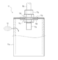
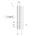
- the abutting member 6 is a member that can realize two contradictory modes, a mode in which the shape can be flexibly deformed and a mode in which the shape is firmly held, with one member, and is shown in FIGS. 3 and 4. As shown, the inner bag 11 and the outer bag 13 that covers the inner bag 11 are provided. With such a configuration, it is possible to easily and surely prevent the inner bag 11 from being worn by repeated use or being cut by chips or the like adhering to the workpiece. The product life of the bag 11 can be extended.
- the inner bag 11 includes a bag body 11a, a connection port 11b, and the like.
- the bag 11a in this embodiment is a member made of nitrile rubber (NBR), a first rubber member formed by heating and press molding raw rubber into a box shape (pentahedron), and a sheet-like second member. It is created using a rubber member. Specifically, a sheet-like second rubber member is attached to the opening of the box-shaped first rubber member by vulcanization welding to form a box (hexahedron), thereby providing airtightness and elasticity. It is set as the structure which obtains the bag 11a which has.
- NBR nitrile rubber
- first rubber member formed by heating and press molding raw rubber into a box shape (pentahedron)
- a sheet-like second member It is created using a rubber member.
- a sheet-like second rubber member is attached to the opening of the box-shaped first rubber member by vulcanization welding to form a box (hexahedron), thereby
- a hole 11f is formed in a substantially central portion of one surface of the bag body 11a, and a connection port 11b which is a member for communicating the inside and outside of the bag body 11a is disposed in the hole 11f. ing.
- the connection port 11b is attached to the hole 11f while securing the airtightness of the hole 11f by inserting the sealing members 11d and 11d and screwing and fastening the nut 11c.
- a vacuum pipe 8b is connected to the connection port 11b, and a filter 11e is disposed at the end of the connection port 11b that is included in the bag 11a.
- the inside of the bag 11a is filled with a granular material 12 that is an aggregate of a plurality of particles.
- the inner bag 11 realizes two contradictory modes, a mode that can be flexibly deformed by filling the granular material 12 inside the bag body 11a, and a mode that holds the shape firmly with a single member. Is possible.
- the filter 11e By providing the filter 11e at the connection port 11b, the particulate matter 12 is prevented from being discharged from the connection port 11b.
- the granular material 12 filled in the bag body 11a has each particle constituting the granular material 12 when the air is removed from the bag body 11a and the volume ratio of the granular material 12 to the inner volume of the bag body 11a increases. The gaps between them are reduced and the particles are moored with each other, and the fluidity of the granular material 12 is lowered and hardened in a lump shape.
- nitrile rubber (NBR) is employ
- adopted is illustrated as a raw material of the inner bag 11 (bag body 11a)
- the raw material which comprises the inner bag 11 is not limited to this.
- various materials can be adopted in accordance with conditions such as work environment.
- the outer bag 13 is a member for covering and protecting the inner bag 11, and includes a bag body 13a, mooring portions 13b and 13b, and the like.
- the bag 13a is a member made of aramid fiber, which is a material having wear resistance and cut resistance. Two substantially rectangular sheet-like members made of aramid fiber are overlapped, and the three sides are sewn together. And it is the member formed in the bag shape.
- the size of the inside of the bag body 13a is a size that can accommodate the inner bag 11 in a displaceable manner. Further, in the vicinity of the open side portion of the bag body 13a that is not sewn, mooring portions 13b and 13b that are portions for hanging the outer bag 13 are attached. In this embodiment, it is set as the simple structure which employ
- aramid fibers are employed as the material for the outer bag 13 (bag body 13a). Since the aramid fiber is a material excellent in wear resistance and cut resistance, the inner bag 11 can be protected from being worn and cut. Further, since the aramid fiber has sufficient flexibility to follow the shape of the workpiece, the inner bag 11 accommodated in the outer bag 13 is accurately copied to the shape of the workpiece in contact with the outer bag 13. Can. For this reason, an aramid fiber is suitable as a raw material which forms the outer bag 13 (bag body 13a). At this time, the aramid fiber can be used in any form such as a woven fabric, a knitted fabric, and a non-woven fabric, but is preferably used in the form of a woven fabric in order to achieve both sufficient flexibility and durability.
- the material which comprises the outer bag 13 is not limited to this, for abrasion resistance and cut resistance Various materials can be adopted as long as they are excellent and have sufficient flexibility to follow the shape of the workpiece.
- the contact member 6 has a configuration in which the inner bag 11 and the outer bag 13 are separated from each other. Since the inner bag 11 and the outer bag 13 can be displaced relative to each other, the deformation of the inner bag 11 is pulled by the outer bag 13. Will not be hindered. For this reason, the inner bag 11 can be deformed along the workpiece shape with high accuracy via the outer bag 13, and the contact member 6 can be made to closely follow the workpiece shape (uneven portion). That is, the abutting member 6 has a structure in which the inner bag 11 and the outer bag 13 are separated from each other, so that the abutting member 6 is more robust than the abutting member having a double-structured bag body in which the inner bag and the outer bag are integrated. Improvements have been made to achieve a proper gripping state. Further, the contact member 6 can replace only the inner bag 11 when the inner bag 11 is damaged, and can replace only the outer bag 13 when the outer bag 13 is damaged. Because it can, it is also economical.
- the abutting member 6 is suspended from the bolts 4 d and 4 d of the clamping part 4 b by anchoring parts 13 b and 13 b of the outer bag 13. Then, with the abutting member 6 (outer bag 13) suspended from the mooring portions 13b and 13b, the nuts 14 and 14 are fastened to the bolts 4d and 4d via the washers 15 and 15 to the clamping portion 4b.
- the contact member 6 is simply and reliably attached. With such a configuration, the contact member 6 can be easily replaced. Thereby, introduction into an actual production line in which wear and cut of the contact member 6 are predicted can be easily realized.
- the abutting member 6 is attached to the pinching portion 4b of the claw portion 4 has been described as an example.
- a bolt projects from the arrangement surface in the pinching portion 5b of the claw portion 5 as well.
- the contact member 6 (not shown) is similarly attached by suspending the contact member 6 from the bolt and fixing the bolt with a nut and a washer.
- the outer bag 13 of the abutting member 6 may be torn (teared portion 20) due to aging deterioration or the like when the number of times of contact with the workpiece increases.
- the outer bag 13 since the outer bag 13 is in direct contact with the workpiece, the outer bag 13 may be contaminated with cutting oil or chips adhering to the workpiece. For this reason, when inspecting whether the abutting member 6 is torn or not, it may be difficult to detect the torn due to dirt, and there is a possibility that the torn occurring in the outer bag 13 may be missed. there were.
- the contact member 6 is configured to cover the outer side of the inner bag 11 filled with the granular material 12 with the outer bag 13.
- the NBR bag body 11 a constituting the inner bag 11 is filled with the granular material 12.
- the outer bag 13 includes a lining 13c on the back surface (the surface on the side in contact with the inner bag 11) of the bag body 13a made of aramid fibers.
- the lining 13c is a film-like PET (polyethylene terephthalate), and is configured to coat the back surface of the bag body 13a by applying PET to the back surface of the bag body 13a.
- the outer bag 13 (bag body 13a) made of aramid fibers and the NBR inner bag 11 (bag body 11a) are in direct contact with each other, and the NBR bag body 11a. Is prevented from being damaged by friction with the aramid fiber bag 13a.
- the light emitting unit 16 includes a light emitting member that emits light by itself or emits light when irradiated with light in a predetermined frequency range.
- the light emitting member As a material (light emitting member) constituting the light emitting unit 16, it absorbs light energy (ultraviolet rays) such as sunlight and illumination light, emits light, and can continue to emit light even after the supply of light energy stops.
- a member (phosphorescent member) There is a member (phosphorescent member).
- the phosphorescent member can be used in an embodiment in which the phosphorescent pigment is used as it is as a paint, an embodiment in which the phosphorescent pigment is mixed with a resin, and used as a sheet-like or thread-like molded product.
- a member (fluorescent member) that emits light when irradiated with ultraviolet rays (black light).
- the fluorescent member can be used in an aspect in which a fluorescent material is used as a paint, an aspect in which the paint is mixed with a resin, and used as a sheet-like or thread-like molded product.
- the light emission part 16 is arrange
- the light emitting unit 16 used in such an arrangement state is an aspect in which the light emitting member is configured in a sheet shape, an aspect in which a thread-like light emitting member is woven into the sheet-like base material, or a paint-like light emitting member on the sheet-like base material It is possible to adopt a mode in which the coating is applied.
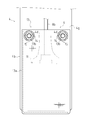
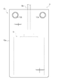
- the first embodiment includes the light emitting portion 16 inside the outer bag 13 so that when the torn portion 20 is generated in the outer bag 13, the light emitting portion 16 appears in a state that can be visually recognized through the torn portion 20. ing.
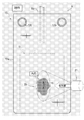
- the contact member 6 is disposed in a dark place as shown in FIG.
- the torn part 20 can be detected.
- the tearing portion 20 When the tearing portion 20 is not generated in the contact member 6, ultraviolet light does not reach the light emitting portion 16 in the outer bag 13, and the surface of the contact member 6 remains dark. It can be easily understood that the portion 20 is not generated.
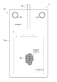
- the tearing portion 20 When the tearing portion 20 is generated in the contact member 6, when the ultraviolet rays reach the light emitting portion 16 through the tearing portion 20, the light emitting portion 16 emits light, so that the shape of the tearing portion 20 appears on the surface of the contact member 6. As a result, the presence of the torn part 20 can be easily grasped.
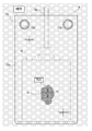
- the torn part 20 can be detected by arranging the contact member 6 in a dark place as shown in FIG.
- the torn member 20 When the torn member 20 is not generated in the contact member 6, the light from the outside does not reach the light emitting unit 16 in the outer bag 13 and the light emitting unit 16 does not emit light. The surface remains in a dark state, and it can be easily understood that the tear bag 20 is not generated in the outer bag 13.
- the torn member 20 When the torn member 20 is generated in the abutting member 6, light from the outside reaches the light emitting unit 16 through the torn portion 20 and is stored. Therefore, when the abutting member 6 is arranged in a dark place, the light emitting unit 16 that emits light. As a result, the shape of the torn part 20 emerges on the surface of the contact member 6, and the existence of the torn part 20 can be easily grasped.
- the torn portion 20 is generated by checking the light emitting portion 16 that emits light through the torn portion 20, the surface of the outer bag 13 is not affected by the contamination state. The torn part 20 can be detected. As a result, damage to the inner bag 11 can be prevented.
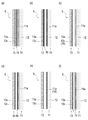
- the light emitting portion 16 is disposed on the surface of the lining 13c of the outer bag 13 (the surface facing the inner bag 11).
- the light emitting section 16 used in such an arrangement state is a mode in which the light emitting member is configured in a sheet shape and is attached to the backing 13c, a mode in which a thread-like light emitting member is woven into the backing 13c, or a paint-like light emitting member on the backing 13c. It is possible to adopt a mode in which the coating is applied.
- the light emission part 16 is comprised by making the lining 13c of the outer bag 13 into a light emitting member.
- the lining 13c itself can be used as the light emitting portion 16 by applying a mixture of PET and a light emitting member (a phosphorescent pigment or a fluorescent material) to the back surface of the bag 13a.
- the light emitting unit 16 is disposed on the inner surface of the outer bag 13.
- the light emission part 16 is arrange
- FIG. The light emitting unit 16 used in such an arrangement employs an aspect in which the light emitting member is configured in a sheet shape and is attached to the surface of the bag body 11a, an aspect in which a paint-like light emitting member is applied to the bag body 11a, and the like. be able to.
- the light emitting portion 16 is configured by using the surface of the bag 11a of the inner bag 11 as a light emitting member.
- the bag body 11a itself can be used as the light emitting unit 16 by creating the bag body 11a using a mixture of NBR and a light emitting member (a phosphorescent pigment or a fluorescent material).
- the light emitting unit 16 is disposed on the outer surface of the inner bag 11. With such a configuration, it is possible to prevent the light emitting portion 16 from being damaged when the torn portion 20 is generated in the outer bag 13. Therefore, oversight of the torn part 20 can be prevented.
- the light emitting portions 16 are arranged on the surface of the bag body 11 a of the inner bag 11 and the back surface of the outer bag 13 (the surface of the lining 13 c).
- the torn portion 20 can be lifted by the light emitting portion 16 left on the surface of the bag body 11a of the inner bag 11.
- the present invention can be used for a gripping device that grips a workpiece while pinching it.
Landscapes
- Engineering & Computer Science (AREA)
- Robotics (AREA)
- Mechanical Engineering (AREA)
- Manipulator (AREA)
Priority Applications (4)
| Application Number | Priority Date | Filing Date | Title |
|---|---|---|---|
| RU2015134646A RU2015134646A (ru) | 2013-02-20 | 2013-04-11 | Захватное устройство |
| US14/768,696 US9387594B2 (en) | 2013-02-20 | 2013-04-11 | Gripping device |
| EP13875610.1A EP2960025A4 (de) | 2013-02-20 | 2013-04-11 | Haltevorrichtung |
| CN201380073196.0A CN104995002A (zh) | 2013-02-20 | 2013-04-11 | 把持装置 |
Applications Claiming Priority (2)
| Application Number | Priority Date | Filing Date | Title |
|---|---|---|---|
| JP2013031562A JP6032054B2 (ja) | 2013-02-20 | 2013-02-20 | 把持装置の当接部材 |
| JP2013-031562 | 2013-02-20 |
Publications (1)
| Publication Number | Publication Date |
|---|---|
| WO2014128982A1 true WO2014128982A1 (ja) | 2014-08-28 |
Family
ID=51390801
Family Applications (1)
| Application Number | Title | Priority Date | Filing Date |
|---|---|---|---|
| PCT/JP2013/060927 Ceased WO2014128982A1 (ja) | 2013-02-20 | 2013-04-11 | 把持装置 |
Country Status (6)
| Country | Link |
|---|---|
| US (1) | US9387594B2 (de) |
| EP (1) | EP2960025A4 (de) |
| JP (1) | JP6032054B2 (de) |
| CN (1) | CN104995002A (de) |
| RU (1) | RU2015134646A (de) |
| WO (1) | WO2014128982A1 (de) |
Families Citing this family (13)
| Publication number | Priority date | Publication date | Assignee | Title |
|---|---|---|---|---|
| JP6650740B2 (ja) * | 2015-12-03 | 2020-02-19 | 住友理工株式会社 | ゴムホース把持装置及びゴムホース抜取方法 |
| US10478974B2 (en) * | 2016-01-20 | 2019-11-19 | Soft Robtics, Inc. | End of arm tools for soft robotic systems |
| EP3405312B1 (de) | 2016-01-20 | 2021-08-11 | Soft Robotics, Inc. | Robotische weiche greifer für überladene greifumgebungen, bewegungen mit hoher beschleunigung, manipulation von nahrungsmitteln sowie automatisierte systeme zur regalbedienung |
| US10569422B2 (en) * | 2016-01-20 | 2020-02-25 | Soft Robotics, Inc. | End of arm tools for soft robotic systems |
| US10661447B2 (en) * | 2016-01-20 | 2020-05-26 | Soft Robotics, Inc. | End of arm tools for soft robotic systems |
| US10647004B2 (en) * | 2016-07-07 | 2020-05-12 | The Board Of Trustees Of The Leland Stanford Junior University | Air-bladder enhanced with gecko-adhesive for grasping applications |
| JP6505762B2 (ja) * | 2017-03-13 | 2019-04-24 | 株式会社東芝 | 把持ツール、把持システム、および把持部の製造方法 |
| USD845372S1 (en) * | 2017-07-27 | 2019-04-09 | JLS Automation | Gripping tool |
| JP6588950B2 (ja) * | 2017-09-27 | 2019-10-09 | 株式会社東芝 | 把持ツール、把持システム、及び把持ツールの制御方法 |
| WO2019075463A1 (en) | 2017-10-13 | 2019-04-18 | Soft Robotics, Inc. | ARM END TOOLS FOR SOFT ROBOTIC SYSTEMS |
| JP7047747B2 (ja) * | 2018-12-17 | 2022-04-05 | トヨタ自動車株式会社 | 把持装置 |
| CN111544296B (zh) * | 2020-06-18 | 2024-03-12 | 四川省人民医院 | 一种血液制品光能保藏袋 |
| CN116175632B (zh) * | 2023-04-23 | 2023-07-11 | 微网优联科技(成都)有限公司 | 一种pcba板上电检测用抓取装置 |
Citations (2)
| Publication number | Priority date | Publication date | Assignee | Title |
|---|---|---|---|---|
| JP2011230260A (ja) | 2010-04-28 | 2011-11-17 | Toyota Motor Corp | 把持装置 |
| JP2012152860A (ja) * | 2011-01-26 | 2012-08-16 | Toyota Motor Corp | 把持装置およびその制御方法 |
Family Cites Families (22)
| Publication number | Priority date | Publication date | Assignee | Title |
|---|---|---|---|---|
| US4561686A (en) * | 1983-08-22 | 1985-12-31 | Raymond Atchley | End effector |
| JPS61150894A (ja) | 1984-12-26 | 1986-07-09 | Nippon Kokan Kk <Nkk> | タ−レツトムアリング船における船体及びタ−レツト間の固定配管の接続装置 |
| JPH0139756Y2 (de) * | 1985-03-07 | 1989-11-29 | ||
| JPS636432A (ja) * | 1986-06-26 | 1988-01-12 | Toshiba Corp | 漏洩検出装置 |
| JP2739216B2 (ja) * | 1988-10-11 | 1998-04-15 | 株式会社ブリヂストン | 部品等のつかみ装置 |
| US5372786A (en) * | 1993-07-02 | 1994-12-13 | Abbott Laboratories | Method of holding a sample container |
| JPH09123082A (ja) * | 1995-11-01 | 1997-05-13 | Kao Corp | 物品把持装置 |
| JP4213252B2 (ja) * | 1998-05-12 | 2009-01-21 | 浜松ホトニクス株式会社 | 光学的検査装置 |
| JP2001249005A (ja) * | 2000-03-06 | 2001-09-14 | Toshiba Corp | 穴検出装置 |
| CN2541836Y (zh) * | 2002-05-14 | 2003-03-26 | 上海亿邦工贸有限公司 | 一种荧光示踪检漏仪 |
| JP4085999B2 (ja) * | 2004-03-22 | 2008-05-14 | アヲハタ株式会社 | 密封容器の検査方法及び内容物入り密封容器製品の製造方法 |
| JP2006093474A (ja) * | 2004-09-24 | 2006-04-06 | Sharp Corp | 発光ダイオード、発光装置及び発光ダイオードの製造方法 |
| CN1632497A (zh) * | 2004-12-30 | 2005-06-29 | 东方汽轮机厂 | 一种水基焊缝渗漏检查液 |
| JP2006252822A (ja) * | 2005-03-08 | 2006-09-21 | Sunarrow Ltd | キートップ部材 |
| JP4648159B2 (ja) * | 2005-11-10 | 2011-03-09 | 本田技研工業株式会社 | 把持装置 |
| JP4881057B2 (ja) | 2006-05-09 | 2012-02-22 | 信号器材株式会社 | レール継ぎ目用絶縁プレート |
| CN102548666B (zh) * | 2009-12-08 | 2014-09-10 | Abb株式会社 | 涂装用盒 |
| WO2012137475A1 (ja) * | 2011-04-07 | 2012-10-11 | パナソニック株式会社 | 光治療装置 |
| JP5588392B2 (ja) * | 2011-04-27 | 2014-09-10 | 株式会社日立製作所 | マニプレータ装置 |
| JP2012243711A (ja) * | 2011-05-24 | 2012-12-10 | Alps Electric Co Ltd | 接点ばね付シート及びスイッチ装置 |
| JP5756678B2 (ja) * | 2011-05-30 | 2015-07-29 | 三井化学株式会社 | 導光性ポリウレタン樹脂および導光部材 |
| JP5846057B2 (ja) * | 2012-06-29 | 2016-01-20 | トヨタ自動車株式会社 | 把持装置による把持方法 |
-
2013
- 2013-02-20 JP JP2013031562A patent/JP6032054B2/ja active Active
- 2013-04-11 WO PCT/JP2013/060927 patent/WO2014128982A1/ja not_active Ceased
- 2013-04-11 CN CN201380073196.0A patent/CN104995002A/zh active Pending
- 2013-04-11 US US14/768,696 patent/US9387594B2/en active Active
- 2013-04-11 EP EP13875610.1A patent/EP2960025A4/de not_active Withdrawn
- 2013-04-11 RU RU2015134646A patent/RU2015134646A/ru not_active Application Discontinuation
Patent Citations (2)
| Publication number | Priority date | Publication date | Assignee | Title |
|---|---|---|---|---|
| JP2011230260A (ja) | 2010-04-28 | 2011-11-17 | Toyota Motor Corp | 把持装置 |
| JP2012152860A (ja) * | 2011-01-26 | 2012-08-16 | Toyota Motor Corp | 把持装置およびその制御方法 |
Non-Patent Citations (1)
| Title |
|---|
| See also references of EP2960025A4 * |
Also Published As
| Publication number | Publication date |
|---|---|
| EP2960025A1 (de) | 2015-12-30 |
| EP2960025A4 (de) | 2016-03-16 |
| CN104995002A (zh) | 2015-10-21 |
| US9387594B2 (en) | 2016-07-12 |
| RU2015134646A (ru) | 2017-03-22 |
| US20150375404A1 (en) | 2015-12-31 |
| JP6032054B2 (ja) | 2016-11-24 |
| JP2014159069A (ja) | 2014-09-04 |
Similar Documents
| Publication | Publication Date | Title |
|---|---|---|
| WO2014128982A1 (ja) | 把持装置 | |
| CN102858502B (zh) | 具有由粒状物质填充的袋构件的抓取装置 | |
| US9554674B2 (en) | Shower rod mounting assembly | |
| CN101054149B (zh) | 吸爪 | |
| WO2009075956A3 (en) | System for removing material from components | |
| CN104470674A (zh) | 固定夹具 | |
| KR101057548B1 (ko) | 블라스팅장치 | |
| CN1081309C (zh) | 管道用快速带压堵漏方法 | |
| KR20160098134A (ko) | 세라믹 마모방지부재가 구비된 컨베이어용 롤러 및 그의 제조방법 | |
| CN205184794U (zh) | 通用型真空机械手夹具 | |
| JP6879558B2 (ja) | 流体漏出個所の補修方法 | |
| DE50209019D1 (de) | Verfahren und vorrichtung zum stillsetzen eines antriebs mit einem matrixumrichter bei netzausfall | |
| CN201721922U (zh) | 耐磨软连接装置 | |
| CN206855260U (zh) | 一种陶瓷砂轮修复卡具及平面磨床 | |
| JP6829361B2 (ja) | 透水性検査装置 | |
| JP5265266B2 (ja) | 接合合成樹脂製配管の接合部の密封性試験装置及びこれを用いた接合合成樹脂製配管の接合部の密封性試験方法 | |
| JP2004271414A (ja) | ホース劣化検出構造体並びにホース及びホース劣化検出方法 | |
| CA2856415C (en) | Method and system for vulcanizing rubber | |
| CN221186588U (zh) | 一种机械臂夹具塑胶气囊 | |
| CN206365476U (zh) | 牛蒡炒料机的保护装置 | |
| JP7081570B2 (ja) | 流体配管または貯液タンクの漏洩箇所補修治具および漏洩箇所の補修方法 | |
| JP6460472B2 (ja) | ライニング材 | |
| JP2005212010A (ja) | エアーブラスト装置 | |
| CN117625065A (zh) | 一种耐磨修补胶布 | |
| CN201250007Y (zh) | 传动滚筒新型复合防滑橡胶板 |
Legal Events
| Date | Code | Title | Description |
|---|---|---|---|
| 121 | Ep: the epo has been informed by wipo that ep was designated in this application |
Ref document number: 13875610 Country of ref document: EP Kind code of ref document: A1 |
|
| REEP | Request for entry into the european phase |
Ref document number: 2013875610 Country of ref document: EP |
|
| WWE | Wipo information: entry into national phase |
Ref document number: 14768696 Country of ref document: US Ref document number: 2013875610 Country of ref document: EP |
|
| WWE | Wipo information: entry into national phase |
Ref document number: IDP00201505048 Country of ref document: ID |
|
| NENP | Non-entry into the national phase |
Ref country code: DE |
|
| ENP | Entry into the national phase |
Ref document number: 2015134646 Country of ref document: RU Kind code of ref document: A |