WO2014129501A1 - Système de détection de passage, procédé de détection de passage, dispositif de détection de passage, programme et support d'enregistrement - Google Patents
Système de détection de passage, procédé de détection de passage, dispositif de détection de passage, programme et support d'enregistrement Download PDFInfo
- Publication number
- WO2014129501A1 WO2014129501A1 PCT/JP2014/053920 JP2014053920W WO2014129501A1 WO 2014129501 A1 WO2014129501 A1 WO 2014129501A1 JP 2014053920 W JP2014053920 W JP 2014053920W WO 2014129501 A1 WO2014129501 A1 WO 2014129501A1
- Authority
- WO
- WIPO (PCT)
- Prior art keywords
- vehicle
- positioning
- unit
- error
- predetermined position
- Prior art date
- Legal status (The legal status is an assumption and is not a legal conclusion. Google has not performed a legal analysis and makes no representation as to the accuracy of the status listed.)
- Ceased
Links
Images


Classifications
-
- G—PHYSICS
- G01—MEASURING; TESTING
- G01S—RADIO DIRECTION-FINDING; RADIO NAVIGATION; DETERMINING DISTANCE OR VELOCITY BY USE OF RADIO WAVES; LOCATING OR PRESENCE-DETECTING BY USE OF THE REFLECTION OR RERADIATION OF RADIO WAVES; ANALOGOUS ARRANGEMENTS USING OTHER WAVES
- G01S19/00—Satellite radio beacon positioning systems; Determining position, velocity or attitude using signals transmitted by such systems
- G01S19/38—Determining a navigation solution using signals transmitted by a satellite radio beacon positioning system
- G01S19/39—Determining a navigation solution using signals transmitted by a satellite radio beacon positioning system the satellite radio beacon positioning system transmitting time-stamped messages, e.g. GPS [Global Positioning System], GLONASS [Global Orbiting Navigation Satellite System] or GALILEO
- G01S19/42—Determining position
- G01S19/48—Determining position by combining or switching between position solutions derived from the satellite radio beacon positioning system and position solutions derived from a further system
- G01S19/49—Determining position by combining or switching between position solutions derived from the satellite radio beacon positioning system and position solutions derived from a further system whereby the further system is an inertial position system, e.g. loosely-coupled
-
- G—PHYSICS
- G07—CHECKING-DEVICES
- G07B—TICKET-ISSUING APPARATUS; FARE-REGISTERING APPARATUS; FRANKING APPARATUS
- G07B15/00—Arrangements or apparatus for collecting fares, tolls or entrance fees at one or more control points
- G07B15/06—Arrangements for road pricing or congestion charging of vehicles or vehicle users, e.g. automatic toll systems
Definitions
- the present invention relates to a passage detection system, a passage detection method, a passage detection device, a program, and a recording medium.
- the present invention relates to a passage detection system, a passage detection method, a passage detection device, a program for causing a computer to function as the passage detection device when a vehicle passes a predetermined position, and a recording medium storing the program About.
- the position of a vehicle is mainly determined by a system using both a GPS (Global Positioning System) method and an autonomous navigation method using a gyro.
- GPS Global Positioning System
- GPS is a system that measures the absolute position of an object by receiving radio waves from a plurality of GPS satellites. However, the position of the vehicle cannot be determined by this system in a building or tunnel where GPS radio waves do not reach.
- Autonomous navigation is used for the purpose of specifying the position of a vehicle in a place where radio waves do not reach.
- autonomous navigation first, an initial position is determined, and then a moving distance and direction from the initial position are calculated by an on-vehicle travel distance sensor and a direction sensor, thereby obtaining the vehicle position.
- the travel distance sensor a vehicle speed sensor that measures a travel distance from the number of rotations of a tire is mainly used.
- the direction sensor a gyro for detecting the turning direction and amount is mainly used.
- DGPS Different GPS
- Patent Document 1 There are various known technologies related to such a background (see, for example, Patent Document 1).
- Patent Document 1 when a vehicle travels in a preset charging area mounted on the vehicle, the vehicle is charged according to the charging rate determined for the charging area and the travel distance in the charging area.
- An apparatus is described. More specifically, this apparatus obtains vehicle position data by obtaining the position of the vehicle in accordance with radio waves from GPS satellites.
- This device is provided with charging area information indicating the position of the charging area, and determines whether or not the vehicle has approached the charging area according to the position of the vehicle indicated by the vehicle position data and the position of the charging area indicated by the charging area information. To do.
- positioning is supported by using position correction data according to an error between the position of the base station obtained according to the radio wave from the GPS satellite and the reference point where the base station is located.
- This device corrects the vehicle position data according to the position correction data.
- This device determines whether or not the vehicle is located in the billing area according to the vehicle position data, and determines the billing amount according to the travel distance and billing rate when the vehicle is located in the billing area. This device can perform appropriate charging for a vehicle passing through the charging area at low cost.
- a positioning method using an in-vehicle DGPS such as the device described in Patent Document 1 is an effective means for efficiently and efficiently positioning the position of a vehicle.
- the position of the vehicle cannot always be measured with a guaranteed accuracy at a position where the sky view is not sufficiently secured or at a position where it is difficult to receive the differential correction radio wave.
- the onboard device that performs the charging processing needs to accurately detect whether the vehicle has passed the toll road charging point.
- the passage detection system for detecting the vehicle when the vehicle passes through a predetermined position, includes a positioning device for positioning the own position using both radio navigation and autonomous navigation, and the vehicle. And a passage detection device for detecting when the vehicle passes a predetermined position.
- the passage detection device corrects the positioning result by the positioning device based on the system error information prepared in advance relating to the systematic error of the positioning result by the positioning device and the traveling state of the vehicle, and specifies the position of the vehicle
- the identification unit and a passage determination unit that determines whether or not the vehicle has passed a predetermined position based on a change with time of the position identified by the position identification unit.
- the passage detection device may further include a traveling state identifying unit that identifies a traveling state of the vehicle based on a change with time of the position identified by the position identifying unit so far.
- the position specifying unit corrects the positioning result by the positioning device based on the system error information prepared in advance regarding the systematic error of the positioning result by the positioning device and the traveling state of the vehicle specified by the traveling state specifying unit.
- the position of the vehicle may be specified.
- the passage detection device includes: a map matching unit that performs map matching on a position specified by the position specifying unit; a first position specified by the position specifying unit; and a second position indicated by a result of map matching performed by the map matching unit.
- a chance error calculation unit that calculates a chance error of the positioning result by the positioning device based on the deviation amount is further included.
- the passage determination unit may determine that the vehicle has not passed the predetermined position when the predetermined position is within the range of the accidental error calculated by the accidental error calculation unit.
- the passage detection system for detecting the vehicle has a positioning device for positioning its own position using both radio navigation and autonomous navigation; And a passage detection device that detects when the vehicle has passed the predetermined position.
- the passage detection device includes a map matching unit that performs map matching on a positioning result obtained by the positioning device, a first position of a positioning result obtained by the positioning device, and a second position indicated by a result of map matching performed by the map matching unit.
- the passage detection method for detecting the vehicle is a positioning result obtained by a positioning device that uses both radio navigation and autonomous navigation to determine its own position. Based on the system error information prepared in advance for the system error of the vehicle and the driving state of the vehicle, the positioning result by the positioning device is corrected to identify the position of the vehicle, and the position identifying step is identified.
- the passage detection method for detecting the vehicle is a positioning result obtained by a positioning device that uses both radio navigation and autonomous navigation to measure its own position.
- the positioning device based on a map matching stage for map matching, a shift amount between a first position of a positioning result by the positioning apparatus and a second position indicated by a map matching result in the map matching stage If the predetermined position is within the range of the accidental error calculated in the accidental error calculation stage and the accidental error calculation stage of calculating the accidental error of the positioning result by the vehicle, the vehicle has not passed the predetermined position And a passage determination stage for determining the above.
- the passage detection device that detects the vehicle is a positioning result obtained by a positioning device that uses both radio navigation and autonomous navigation to position itself.
- a position specifying unit for correcting the positioning result by the positioning device based on the system error information prepared in advance relating to the system error of the vehicle and the traveling state of the vehicle, and the position specified by the position specifying unit And a passage determination unit that determines whether or not the vehicle has passed a predetermined position based on the change over time.
- a program for causing a computer to function as a passage detection device for detecting when a vehicle passes a predetermined position uses the computer in combination with radio navigation and autonomous navigation.
- a map matching unit that performs map matching on a positioning result obtained by a positioning device that measures its own position, a first position of a positioning result obtained by the positioning device, and a second position indicated by a result of map matching performed by the map matching unit.
- a coincidence error calculation unit that calculates a coincidence error of a positioning result by the positioning device based on a deviation amount, and when the predetermined position is within the range of the coincidence error calculated by the coincidence error calculation unit, the vehicle is It is made to function as a passage determination unit that determines that the predetermined position has not been passed.
- a program that causes a computer to function as a passage detection device that detects when a vehicle passes a predetermined position uses a combination of radio navigation and autonomous navigation.
- Position identification that identifies the position of the vehicle by correcting the positioning result by the positioning device based on the system error information prepared in advance regarding the systematic error of the positioning result by the positioning device that measures the own position and the running state of the vehicle
- a position determination unit that functions as a passage determination unit that determines whether or not the vehicle has passed a predetermined position based on a change over time of the position specified by the position specifying unit.
- a program for causing a computer to function as a passage detection device that detects when a vehicle passes a predetermined position uses the computer in combination with radio navigation and autonomous navigation.
- a map matching unit that performs map matching on a positioning result obtained by a positioning device that measures its own position, a first position of a positioning result obtained by the positioning device, and a second position indicated by a result of map matching performed by the map matching unit.
- a coincidence error calculation unit that calculates a coincidence error of a positioning result by the positioning device based on a deviation amount, and when the predetermined position is within the range of the coincidence error calculated by the coincidence error calculation unit, the vehicle is It is made to function as a passage determination unit that determines that the predetermined position has not been passed.
- a recording medium recording a program that causes a computer to function as a passage detection device that detects when a vehicle has passed a predetermined position, the computer uses radio navigation and autonomous navigation.
- the position of the vehicle is corrected by correcting the positioning result by the positioning device based on the system error information prepared in advance relating to the systematic error of the positioning result by the positioning device that measures the position of the vehicle by using the position of the vehicle and the running state of the vehicle.
- a program for causing the vehicle to function as a passage determining unit that determines whether or not the vehicle has passed a predetermined position based on a change over time of the position specified by the position specifying unit.
- a recording medium recording a program for causing a computer to function as a passage detection device that detects when a vehicle passes a predetermined position.
- a map matching unit for map-matching a positioning result obtained by a positioning device that measures its own position together with navigation, a first position of a positioning result obtained by the positioning device, and a map matching result of the map matching unit
- a coincidence error calculation unit for calculating a coincidence error of a positioning result by the positioning device based on a deviation amount from position 2, and the predetermined position is within the range of the coincidence error calculated by the coincidence error calculation unit
- a program that causes the vehicle to function as a passage determination unit that determines that the vehicle has not passed through the predetermined position is recorded.
- passage detection system passage detection method, passage detection device, program, and recording medium, for example, even if the vehicle is traveling on a road where the aerial view cannot be sufficiently secured, When the vehicle passes through a predetermined position without being affected, it can be detected.
- FIG. It is a figure which shows an example of the utilization environment of the passage detection system 100 which concerns on one Embodiment. It is a figure which shows an example of the block configuration of the onboard equipment 110.
- FIG. It is a figure which shows an example of the information stored in the system
- strain error information storage part 120 in a table format.
- strain error information storage part 120 It is a figure which shows an example of the information stored in the accounting point information storage part 121 in a table format.
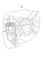
- FIG. 1 shows an example of a usage environment of a passage detection system 100 according to an embodiment.
- the passage detection system 100 is a system that detects when a vehicle passes a charging point.
- the billing point is a position where billing processing should be performed in road pricing.
- the billing point may be an example of a “predetermined position” in the present invention.
- the passage detection system 100 includes an on-vehicle device 110, a GPS receiver 130, and a display 150.
- the vehicle-mounted device 110 may be an example of the “passage detection device” in the present invention.
- the GPS receiver 130 may be an example of the “positioning device” in the present invention.
- the GPS receiver 130 is a device for positioning its own position by using both radio navigation and autonomous navigation. More specifically, the GPS receiver 130 includes a GPS antenna, an accelerometer, and an angular velocity meter.
- the GPS antenna is an antenna that receives radio waves from GPS satellites.
- the accelerometer is a measuring instrument that measures a change in acceleration when the vehicle moves.
- the angular velocity meter is a measuring instrument that measures a change in angular velocity when the vehicle moves.
- the GPS receiver 130 is provided at a position where the GPS antenna is not shielded, such as on the dashboard D of the vehicle.
- the GPS receiver 130 is electrically connected to the vehicle-mounted device 110.
- the GPS receiver 130 measures its own position by using both GPS radio navigation and autonomous navigation using an accelerometer and an angular velocity meter.
- the GPS receiver 130 outputs data indicating the positioning result to the vehicle-mounted device 110.
- the vehicle-mounted device 110 is a device that detects when a vehicle passes a charging point. More specifically, the vehicle-mounted device 110 is provided at a position that can be reached by the driver without disturbing driving, such as the side surface of the center console C of the vehicle.
- the vehicle-mounted device 110 is electrically connected to the GPS receiver 130 and the display 150.
- An IC (Integrated Circuit) card is inserted into the card slot I of the vehicle-mounted device 110.
- application data and the like for realizing a security function are mounted in addition to a nonvolatile memory for storing user information of the passage detection system 100, billing information including a usage history, and the like. Is done.
- the vehicle-mounted device 110 When the vehicle-mounted device 110 receives input of data output from the GPS receiver 130, the vehicle-mounted device 110 determines whether or not the vehicle has passed the charge point. If the vehicle-mounted device 110 determines that the vehicle has passed the charging point, it performs charging processing. The in-vehicle device 110 outputs data indicating the result of the charging process to the display 150.
- the display 150 is a device that displays characters and figures. More specifically, the display 150 is provided at a position where the driver can visually recognize, such as the center console C of the vehicle.
- the display 150 is electrically connected to the vehicle-mounted device 110. When the display 150 receives input of data output from the vehicle-mounted device 110, the display 150 displays the result of the accounting process indicated by the data.
- the passage detection system 100 includes one GPS receiver 130 and a display 150
- the passage detection system 100 may include a plurality of GPS receivers 130 and a display 150.
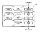
- FIG. 2 shows an example of a block configuration of the vehicle-mounted device 110.
- the vehicle-mounted device 110 includes a positioning result data input receiving unit 111, a position specifying unit 112, a map matching unit 113, a traveling state specifying unit 114, a chance error calculating unit 115, a passage determining unit 116, a charging processing unit 117, a data output unit 118, A map data storage unit 119, a systematic error information storage unit 120, and a charging point information storage unit 121 are included.
- a positioning result data input receiving unit 111 includes a positioning result data input receiving unit 111, a position specifying unit 112, a map matching unit 113, a traveling state specifying unit 114, a chance error calculating unit 115, a passage determining unit 116, a charging processing unit 117, a data output unit 118, A map data storage unit 119, a systematic error information storage unit 120, and a charging point information storage unit 121 are included.
- the function and operation of each component
- the positioning result data input receiving unit 111 receives input of data indicating the positioning result output from the GPS receiver 130.
- the position specifying unit 112 corrects the positioning result by the GPS receiver 130 based on the system error information prepared in advance related to the system error of the positioning result by the GPS receiver 130 and the traveling state of the vehicle, and thereby determines the position of the vehicle. Is identified. More specifically, the position specifying unit 112 is based on the system error information prepared in advance regarding the system error of the positioning result by the GPS receiver 130 and the running state of the vehicle specified by the running state specifying unit 114. The position of the vehicle is specified by correcting the positioning result by the GPS receiver 130.
- the traveling state of the vehicle roughly indicates either whether the vehicle is traveling or stopped.
- the traveling state of a traveling vehicle refers to any of straight traveling, traveling while turning right, or traveling while turning left.
- the systematic error is measured by systematically shifting the position coordinate of the positioning result by the GPS receiver 130 with respect to the true position coordinate of the position as long as positioning is performed at the same position in the same traveling state. It shall indicate an error.
- the true position coordinates are position coordinates on a map, for example.
- the map matching unit 113 performs map matching on the position specified by the position specifying unit 112.
- the map matching is a process for forcibly matching the position specified by the position specifying unit 112 outside the road on the map on the assumption that the vehicle runs on the road. .
- the traveling state identifying unit 114 identifies the traveling state of the vehicle based on the temporal change of the position identified by the position identifying unit 112 so far.
- the accidental error calculation unit 115 performs positioning by the GPS receiver 130 based on the amount of deviation between the first position specified by the position specifying unit 112 and the second position indicated by the map matching result obtained by the map matching unit 113. Calculate the accidental error of the result.
- the accidental error refers to an error that varies for each positioning even if positioning is performed at the same position in the same traveling state.
- the passage determination unit 116 determines whether or not the vehicle has passed the charging point based on the change over time of the position specified by the position specifying unit 112. More specifically, the passage determination unit 116 determines that the vehicle has not passed the charging point when the charging point is within the range of the accidental error calculated by the accidental error calculation unit 115.
- the billing processing unit 117 performs billing processing when the vehicle passes the billing point.
- the data output unit 118 outputs data indicating the result of the billing process to the display 150.
- the map data storage unit 119 stores digital map data.
- the digital map is a map that can be computerized and digitized.
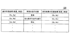
- FIG. 3 shows an example of information stored in the systematic error information storage unit 120 in a table format.
- the systematic error information storage unit 120 information on true position coordinates (longitude, latitude), a running state of the vehicle, and position coordinates (longitude, latitude) of the positioning result are stored in association with each other. Further, the information stored in the systematic error information storage unit 120 may be an example of “systematic error information” in the present invention.
- the information of “true position coordinates (longitude, latitude)” is information indicating the longitude and latitude on the digital map. More specifically, the information of “true position coordinates (longitude, latitude)” indicates the longitude and latitude on the digital map of the position where a systematic error occurs in the positioning result of the GPS receiver 130 around the charging point. .
- the “vehicle running state” information is information indicating the running state of the vehicle at the position indicated by the “true position coordinates (longitude, latitude)” information.
- the information on the “position coordinates (longitude, latitude) of the positioning result” indicates that the driving state of the vehicle is indicated by the information of “vehicle driving state” at the position indicated by the information of “true position coordinates (longitude, latitude)”. It is the information which shows the positioning result of the GPS receiver 130 in the case of being in a state.
- the amount of deviation between the position coordinates indicated by the information of “true position coordinates (longitude, latitude)” and the position coordinates indicated by the information of “position coordinates (longitude, latitude) of the positioning result” Is a systematic error when the traveling state of the vehicle is the state represented by the information “traveling state of the vehicle” at the position indicated by the information “true position coordinates (longitude, latitude)”.
- the true position coordinate where the vehicle exists indicates “(Ea, Na)”. Even if the position coordinate of the positioning result by the GPS receiver 130 is “(Eb, Nb)”, if the running state of the vehicle at that time is “stop”, the true position where the vehicle exists The coordinates indicate “(Ed, Nd)”. In addition, even if the true position coordinate is “(Ea, Na)”, if the traveling state of the vehicle at that position is “traveling while turning right”, the positioning result by the GPS receiver 130 is “(Ec , Nc) ”.
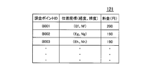
- FIG. 4 shows an example of information stored in the charging point information storage unit 121 in a table format.
- the charging point information storage unit 121 stores charging point ID (identifier), position coordinates (longitude, latitude), and fee (yen) in association with each other.
- charging point ID is an identification code for uniquely identifying each charging point among a plurality of charging points.
- the information of “position coordinates (longitude, latitude)” is information indicating the longitude and latitude on the digital map of the charging point indicated by the information of “charging point ID”.
- the “charge (yen)” information is information indicating the amount of charge to be charged when passing the charging point indicated by the information of “charging point ID”.
- a charging point having a position coordinate of “(Ef, Nf)” is a charging point for which “200 (yen)” is charged.
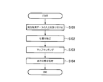
- FIG. 5 shows an example of the operation flow of the vehicle-mounted device 110.
- this operation flow a process for map matching the position of the vehicle will be described in detail.
- both FIGS. 1 to 4 are referred to.
- the GPS receiver 130 uses GPS radio navigation and autonomous navigation using an accelerometer and an angular velocity meter in combination to measure its own position at predetermined intervals.
- the GPS receiver 130 sequentially outputs data indicating the positioning result to the vehicle-mounted device 110.
- the positioning result data input receiving unit 111 of the in-vehicle device 110 receives the input of the data indicating the positioning result output from the GPS receiver 130 (S101), the positioning result data input receiving unit 111 sends the data to the position specifying unit 112.
- the position specifying unit 112 of the vehicle-mounted device 110 receives the data sent from the positioning result data input receiving unit 111
- the position specifying unit 112 uses the information stored in the systematic error information storage unit 120 and the data received from the traveling state specifying unit 114. Based on the traveling state of the vehicle shown, the positioning result indicated by the data received from the positioning result data input receiving unit 111 is corrected to identify the position of the vehicle (S102).
- the position coordinate indicated by the data received from the positioning result data input receiving unit 111 is “(Ea, Na)”
- the vehicle driving state indicated by the latest data received from the driving state specifying unit 114 is “
- the position specifying unit 112 has information “position coordinates (longitude, latitude)” of “(Ea, Na)” among the information stored in the systematic error information storage unit 120,
- the information “(Eb, Nb)” of “true position coordinates (longitude, latitude)” stored in association with the information “traveling state of the vehicle” in correspondence with “straight ahead” is read.
- the position specifying unit 112 specifies the position coordinates (Ea, Na) as the corrected vehicle position.
- the same position coordinates as the positioning results indicated by the data sent from the positioning result data input receiving unit 111 are stored as information of “positional coordinates (longitude, latitude) of positioning results” in the systematic error information storage unit 120. If not, the position specifying unit 112 specifies the position coordinates of the positioning result indicated by the data received from the positioning result data input receiving unit 111 as the position of the vehicle. This is because when no corresponding information is stored in the systematic error information storage unit 120, it means that no systematic error has occurred at that position.
- the position specifying unit 112 sends data indicating the position coordinates of the vehicle specified in this way to the map matching unit 113, the traveling state specifying unit 114, and the accidental error calculating unit 115.
- the map matching unit 113 of the vehicle-mounted device 110 receives the data sent from the position specifying unit 112, the map matching is performed on the position coordinates indicated by the data (S103).
- the map matching unit 113 uses the road shape on the map, the running pattern history of the vehicle, and the like as data, and maps the position coordinates indicated by the data sent from the position specifying unit 112 using a heuristic algorithm. Match.
- the map matching unit 113 sends data indicating the position coordinates after map matching to the traveling state specifying unit 114, the accidental error calculating unit 115, and the passage determining unit 116.
- the traveling state specifying unit 114 of the vehicle-mounted device 110 receives the data sent from the position specifying unit 112 and the map matching unit 113, respectively, the traveling state of the vehicle is determined based on the temporal change of the position coordinates indicated by these data.
- a state is specified (S104).
- the traveling state identification unit 114 identifies whether the vehicle is traveling or stopped based on the temporal change of the position coordinates indicated by the data received from the position identification unit 112. For example, when the amount of change over time of the position coordinates indicated by the plurality of data received from the position specifying unit 112 within a predetermined time is less than a predetermined value, the traveling state specifying unit 114 specifies that the vehicle is stopped. To do. In addition, when the amount of change over time of the position coordinates indicated by the plurality of data received from the position specifying unit 112 within a predetermined time is equal to or greater than a predetermined value, the running state specifying unit 114 specifies that the vehicle is running. To do.
- the traveling state identifying unit 114 determines whether the vehicle is traveling straight or turning right based on the temporal change in the position coordinates indicated by the data received from the map matching unit 113. Determine if it is progressing or turning left. For example, when a change with time in position coordinates indicated by a plurality of data received from the map matching unit 113 within a predetermined time is linear, the traveling state specifying unit 114 specifies that the vehicle is traveling straight. In addition, when the temporal change of the position coordinates indicated by the plurality of data received from the map matching unit 113 within a predetermined time has changed to the northeast or southwest, the traveling state specifying unit 114 turns the vehicle to the right. While progressing, identify. In addition, when the time-dependent change in the position coordinates indicated by the plurality of data received from the map matching unit 113 within a predetermined time has changed to northwest or southeast, the driving state specifying unit 114 turns the vehicle to the left. While progressing, identify.
- the traveling state identification unit 114 sends data indicating the identified traveling state of the vehicle to the position identification unit 112.
- the position specifying unit 112 When the position specifying unit 112 receives the data sent from the positioning result data input receiving unit 111, the position specifying unit 112 receives the data stored in the systematic error information storage unit 120 and the data indicated by the data received from the traveling state specifying unit 114. Based on the running state, the positioning result indicated by the data received from the positioning result data input receiving unit 111 is corrected to identify the position of the vehicle (S102).
- the vehicle-mounted device 110 repeats the processing of steps S101 to S104 each time it receives input of data output from the GPS receiver 130, and map-matches the position of the vehicle.
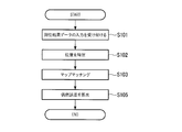
- FIG. 6 shows an example of the operation flow of the vehicle-mounted device 110.
- the process for calculating the range of the chance error at the current position of the vehicle will be described in detail.
- FIGS. 1 to 5 and FIG. 7 are referred to.
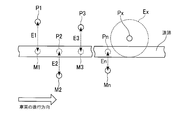
- FIG. 7 shows an example of a method for calculating the range of chance errors. Further, among the steps of the operation flow shown in FIG. 6, steps having the same reference numerals as those in the operation flow shown in FIG. 5 indicate similar operations.
- the position specifying unit 112 Each time the position specifying unit 112 specifies the position coordinates of the vehicle, the position specifying unit 112 sends data indicating the position coordinates to the chance error calculating unit 115. Further, each time map matching is performed, the map matching unit 113 sends data indicating the position coordinates after map matching to the accidental error calculation unit 115.
- the accidental error calculation unit 115 of the vehicle-mounted device 110 receives the data sent from the position specifying unit 112 and the map matching unit 113, respectively, and the position coordinates indicated by the data received from the position specifying unit 112 and the map matching unit 113. Based on the amount of deviation from the position coordinates indicated by the data received from, the range of the accidental error of the positioning result by the GPS receiver 130 is sequentially calculated (S105).
- the position coordinates indicated by the data received from the position specifying unit 112 may be an example of the “first position” in the present invention.
- the position coordinates indicated by the data received from the map matching unit 113 may be an example of the “second position” in the present invention.
- Deviation amounts E1 to En between the position coordinates of the respective positions P1 to Pn specified by the position specifying unit 112 and the position coordinates of the respective positions M1 to Mn as a result of map matching of the respective positions P1 to Pn by the map matching unit 113 The root mean square Err is calculated (formula (1)).
- the chance error calculation unit 115 multiplies the value of the root mean square Err by N (N is a positive number) to calculate the range of the chance error.
- N is a positive number
- the range of the chance error becomes wider as the value of N is larger.
- the coincidence error calculation unit 115 sends data indicating the range of the calculated coincidence error to the passage determination unit 116.
- the vehicle-mounted device 110 can perform processing with reference to the range of the chance error at the current position of the vehicle.
- FIG. 8 shows an example of the operation flow of the vehicle-mounted device 110.
- this operation flow a process for detecting when a vehicle passes a charging point will be described in detail.
- both FIGS. 1 to 7 are referred to.
- steps denoted by the same reference numerals as those in the operation flow shown in FIGS. 5 and 6 indicate the same operation.
- the map matching unit 113 sends data indicating the position coordinates after map matching to the passage determining unit 116 each time map matching is performed. In addition, every time the accidental error calculation unit 115 calculates the range of accidental miscalculation, the accidental error calculation unit 115 sends data indicating the range of the accidental error to the passage determination unit 116.
- the passage determination unit 116 of the in-vehicle device 110 receives the data sent from the map matching unit 113 and the accidental error calculation unit 115, whether the vehicle has passed the charge point based on the information indicated by these data. It is sequentially determined whether or not (S106). For example, the passage determination unit 116 uses the position coordinates after map matching indicated by the data received from the map matching unit 113 and the information of “position coordinates (longitude, latitude)” stored in the charging point information storage unit 121. Compare the position coordinates shown.
- the passage determination unit 116 determines that the “position coordinates (longitude, The pass determination is started for the billing point at the position coordinate indicated by the “latitude” information. For example, the pass determination is performed while the position coordinates of the billing point to be passed are within the range of the chance error indicated by the data received from the chance error calculation unit 115 centered on the position coordinates after the map matching. The unit 116 determines that the vehicle has not passed the charging point (S106: No).
- the passage determination unit 116 determines that the vehicle has passed the charging point (S106). : Yes).
- the passing determining unit 116 transmits data indicating information on the “charging point ID” of the charging point to the charging processing unit 117.
- the billing processing unit 117 of the in-vehicle device 110 Upon receiving the data sent from the passage determination unit 116, the billing processing unit 117 of the in-vehicle device 110 receives the data from the passage determination unit 116 among the “charge (yen)” information stored in the billing point information storage unit 121. The “charge (yen)” information stored in association with the “charge point ID” information indicated by the received data is read. The billing processing unit 117 charges the toll by removing the electronic money equivalent to the fee indicated by the information from the IC card inserted in the card slot I of the vehicle-mounted device 110 (S107). The billing processing unit 117 sends data indicating the result of the billing processing to the data output unit 118.
- the data output unit 118 of the vehicle-mounted device 110 When the data output unit 118 of the vehicle-mounted device 110 receives the data sent from the billing processing unit 117, the data output unit 118 outputs data for displaying the result of the billing process indicated by the data to the display 150 (S108).
- the result of the billing process is displayed on the display 150.
- the passage detection system 100 may include a speaker instead of the display 150 or together with the display 150.
- the data output unit 118 of the vehicle-mounted device outputs data for outputting the result of the charging process as a sound to the speaker.
- the passage detection system 100 includes the GPS receiver 130 that measures its own position by using both radio navigation and autonomous navigation. Moreover, the passage detection system 100 includes an in-vehicle device 110 that detects when a vehicle passes a charging point. The vehicle-mounted device 110 specifies the position of the vehicle by correcting the positioning result by the positioning device based on the system error information prepared in advance regarding the system error of the positioning result by the GPS receiver 130 and the traveling state of the vehicle. . The in-vehicle device 110 determines whether or not the vehicle has passed the charging point based on the change over time of the specified position.
- the vehicle has passed the charging point without being affected by the system error of the positioning result by the GPS receiver 130. If so, it can be detected.
- the vehicle-mounted device 110 identifies the running state of the vehicle based on the temporal change in the vehicle position identified up to now.
- the in-vehicle device 110 corrects the positioning result by the GPS receiver 130 based on the system error information prepared in advance regarding the system error of the positioning result by the GPS receiver 130 and the identified running state of the vehicle. Identify the location.
- the driving state of the vehicle can be specified each time the position of the vehicle is specified.
- the vehicle-mounted device 110 performs map matching on the position of the specified vehicle.
- the in-vehicle device 110 calculates a coincidence error of the positioning result by the GPS receiver 130 based on the amount of deviation between the specified vehicle position and the position indicated by the map matching result.
- the vehicle-mounted device 110 determines that the vehicle has not passed the charging point when the charging point is within the range of the calculated accidental error.
- the vehicle-mounted device 110 uses the GPS receiver 130 based on the system error information prepared in advance regarding the system error of the positioning result obtained by the GPS receiver 130 and the traveling state of the vehicle. Based on the amount of deviation between the first position of the vehicle specified by correcting the first position and the second position indicated by the result of map matching the first position, the accidental error of the positioning result by the GPS receiver 130 is calculated. The example to calculate was demonstrated. However, the vehicle-mounted device 110 can calculate the accidental error of the positioning result by the GPS receiver 130 by another method. For example, the in-vehicle device 110 receives the GPS signal based on the amount of deviation between the first position of the positioning result by the GPS receiver 130 and the second position indicated by the map matching result of the positioning result by the GPS receiver 130. The accidental error of the positioning result by the machine 130 may be calculated.
- FIG. 9 shows an example of a hardware configuration of a computer 800 that constitutes the vehicle-mounted device 110 according to the present embodiment.
- a computer 800 includes a CPU (Central Processing Unit) 802, a RAM (Random Access Memory) 803, a graphic controller 804, and a display 805 that are mutually connected by a host controller 801, and input / output An input / output unit having a communication interface 807, a hard disk drive 808, and a CD-ROM (Compact Disk Only Memory) drive 809 connected to each other by the controller 806, and a ROM (Read Only Memory) connected to the input / output controller 806 810, legacy input / output having flexible disk drive 811 and input / output chip 812 Provided with a door.
- a CPU Central Processing Unit
- RAM Random Access Memory
- FIG. 9 shows an example of a hardware configuration of a computer 800 that constitutes the vehicle-mounted device 110 according to the present embodiment.
- a computer 800 includes a CPU (Central Processing Unit) 802, a RAM (Ran
- the host controller 801 connects the RAM 803, the CPU 802 that accesses the RAM 803 at a high transfer rate, and the graphic controller 804.
- the CPU 802 operates based on programs stored in the ROM 810 and the RAM 803 and controls each unit.
- the graphic controller 804 acquires image data generated on a frame buffer provided in the RAM 803 by the CPU 802 and the like and displays the image data on the display 805.
- the graphic controller 804 may include a frame buffer for storing image data generated by the CPU 802 or the like.
- the input / output controller 806 connects the host controller 801 to the communication interface 807, the hard disk drive 808, and the CD-ROM drive 809, which are relatively high-speed input / output devices.
- the hard disk drive 808 stores programs and data used by the CPU 802 in the computer 800.
- the CD-ROM drive 809 reads a program or data from the CD-ROM 892 and provides it to the hard disk drive 808 via the RAM 803.
- the input / output controller 806 is connected to the ROM 810, the flexible disk drive 811 and the input / output chip 812, which are relatively low-speed input / output devices.
- the ROM 810 stores a boot program that is executed when the computer 800 is started and / or a program that depends on the hardware of the computer 800.
- the flexible disk drive 811 reads a program or data from the flexible disk 893 and provides it to the hard disk drive 808 via the RAM 803.
- the input / output chip 812 connects the flexible disk drive 811 to the input / output controller 806 and connects various input / output devices to the input / output controller 806 via, for example, a parallel port, serial port, keyboard port, mouse port, and the like. To do.
- the program provided to the hard disk drive 808 via the RAM 803 is stored in a recording medium such as a flexible disk 893, a CD-ROM 892, or an IC (Integrated Circuit) card and provided by the user.
- the program is read from the recording medium, installed in the hard disk drive 808 in the computer 800 via the RAM 803, and executed by the CPU 802.
- a program that is installed in the computer 800 and causes the computer 800 to function as the vehicle-mounted device 110 causes the computer 800 to have system error information prepared in advance relating to the system error of the positioning result by the GPS receiver 130 in step S102, and the running state of the vehicle.
- the position specifying unit 112 that corrects the positioning result by the GPS receiver 130 to specify the position of the vehicle and the time-dependent change of the position specified by the position specifying unit 112 are Is made to function as a passage determination unit 116 that determines whether or not a billing point has passed.
- the program causes the computer 800 to check the running state identifying unit 114 that identifies the traveling state of the vehicle in step S104 based on the change over time of the position identified by the position identifying unit 112 so far, and the GPS receiver.
- the positioning result by the GPS receiver 130 is corrected based on the system error information prepared in advance relating to the systematic error of the positioning result 130 and the traveling state of the vehicle identified by the traveling state identifying unit 114. You may make it function as the position specific
- the program includes a map matching unit 113 that performs map matching in step S103 on the position specified by the position specifying unit 112, a position specified by the position specifying unit 112, and a map matching unit 113 that performs map matching.
- the random error calculation unit 115 that calculates the random error of the positioning result by the GPS receiver 130, and the range of the random error calculated by the random error calculation unit 115 If there is a charging point, the pass determination unit 116 may determine that the vehicle has not passed the charging point in step S106.
- the information processing described in these programs is read into the computer 800, whereby the positioning result data input receiving unit 111 and the position specifying unit 112, which are specific means in which the software and the various hardware resources described above cooperate. , Map matching unit 113, driving state specifying unit 114, chance error calculating unit 115, passage determining unit 116, charging processing unit 117, data output unit 118, map data storage unit 119, systematic error information storage unit 120, and charging point information It functions as the storage unit 121.
- Map matching unit 113 Map matching unit 113, driving state specifying unit 114, chance error calculating unit 115, passage determining unit 116, charging processing unit 117, data output unit 118, map data storage unit 119, systematic error information storage unit 120, and charging point information It functions as the storage unit 121.
- the CPU 802 executes a communication program loaded on the RAM 803 and executes a communication interface based on the processing content described in the communication program.
- a communication process is instructed to 807.
- the communication interface 807 reads transmission data stored in a transmission buffer area or the like provided on a storage device such as the RAM 803, the hard disk drive 808, the flexible disk 893, or the CD-ROM 892, and sends it to the network.
- the reception data transmitted or received from the network is written into a reception buffer area or the like provided on the storage device.
- the communication interface 807 may transfer transmission / reception data to / from the storage device by the direct memory access method. Instead, the CPU 802 reads data from the transfer source storage device or the communication interface 807.
- the transmission / reception data may be transferred by writing the data to the transfer destination communication interface 807 or the storage device.
- the CPU 802 transfers all or a necessary portion of the files or database stored in the external storage device such as the hard disk drive 808, CD-ROM 892, and flexible disk 893 to the RAM 803 by direct memory access transfer or the like.
- the data is read and various processes are performed on the data on the RAM 803.
- the CPU 802 writes the processed data back to the external storage device by direct memory access transfer or the like.
- the RAM 803 can be regarded as temporarily holding the contents of the external storage device, in the present embodiment, the RAM 803 and the external storage device are collectively referred to as a memory, a storage unit, a storage device, or the like.
- Various types of information such as various programs, data, tables, and databases in the present embodiment are stored on such a storage device and are subjected to information processing.
- the CPU 802 can hold a part of the RAM 803 in the cache memory and perform reading and writing on the cache memory.
- the cache memory bears a part of the function of the RAM 803, the cache memory is also included in the RAM 803, the memory, and / or the storage device unless otherwise indicated.
- the CPU 802 performs various operations, such as various operations, information processing, condition determination, information retrieval, replacement, and the like described in the present embodiment for data read from the RAM 803 and specified by a command sequence of the program. Is written back to the RAM 803. For example, when performing the condition determination, the CPU 802 satisfies the conditions such that the various variables shown in the present embodiment are larger, smaller, above, below, or equal to other variables or constants. If the condition is satisfied or not satisfied, the program branches to a different instruction sequence or calls a subroutine.
- the CPU 802 can search for information stored in a file in a storage device or a database. For example, when a plurality of entries in which the attribute value of the second attribute is associated with the attribute value of the first attribute are stored in the storage device, the CPU 802 stores the plurality of entries stored in the storage device. An entry that matches the condition in which the attribute value of the first attribute is designated is retrieved, and the attribute value of the second attribute stored in the entry is read. Thereby, the attribute value of the 2nd attribute matched with the 1st attribute which satisfy
- the storage medium is an optical recording medium such as a DVD (Digital Versatile Disk) or CD (Compact Disk), a magneto-optical recording medium such as an MO (Magneto-Optical disk), or a tape medium.
- a semiconductor memory such as an IC card can be used.
- a storage medium such as a hard disk or RAM provided in a server system connected to a dedicated communication network or the Internet may be used as a recording medium, and the program may be provided to the computer 800 via the network.
- passage detection system passage detection method, passage detection device, program, and recording medium, for example, even if the vehicle is traveling on a road where the aerial view cannot be sufficiently secured, When the vehicle passes through a predetermined position without being affected, it can be detected.
Landscapes
- Engineering & Computer Science (AREA)
- Radar, Positioning & Navigation (AREA)
- Remote Sensing (AREA)
- Physics & Mathematics (AREA)
- General Physics & Mathematics (AREA)
- Computer Networks & Wireless Communication (AREA)
- Business, Economics & Management (AREA)
- Finance (AREA)
- Navigation (AREA)
- Instructional Devices (AREA)
- Devices For Checking Fares Or Tickets At Control Points (AREA)
- Position Fixing By Use Of Radio Waves (AREA)
Abstract
L'invention porte sur un système de détection de passage, lequel système comporte : un dispositif de positionnement (130), qui emploie tout à la fois une navigation par radio et une navigation autonome pour déterminer la position de celui-ci ; et un dispositif de détection de passage (110), qui, dans des cas dans lesquels un véhicule est passé par une position prescrite, détecte que le véhicule est passé par la position prescrite. Le dispositif de détection de passage (110) comporte : une unité de spécification de position, qui, sur la base d'un état de déplacement du véhicule et d'une information d'erreur systématique pré-préparée associée à une erreur systématique dans des résultats de positionnement à partir du dispositif de positionnement (130), corrige un résultat de positionnement à partir du dispositif de positionnement (130), et spécifie une position du véhicule ; et une unité de détermination de passage, qui détermine si le véhicule est ou non passé par la position prescrite sur la base du changement au cours du temps dans la position spécifiée par l'unité de spécification de position.
Priority Applications (1)
| Application Number | Priority Date | Filing Date | Title |
|---|---|---|---|
| SG11201506575SA SG11201506575SA (en) | 2013-02-22 | 2014-02-19 | Passage detection system, passage detection method, passage detection device, program, and recording medium |
Applications Claiming Priority (2)
| Application Number | Priority Date | Filing Date | Title |
|---|---|---|---|
| JP2013033201A JP6103980B2 (ja) | 2013-02-22 | 2013-02-22 | 通過検知システム、通過検知方法、通過検知装置、プログラム、及び記録媒体 |
| JP2013-033201 | 2013-02-22 |
Publications (1)
| Publication Number | Publication Date |
|---|---|
| WO2014129501A1 true WO2014129501A1 (fr) | 2014-08-28 |
Family
ID=51391287
Family Applications (1)
| Application Number | Title | Priority Date | Filing Date |
|---|---|---|---|
| PCT/JP2014/053920 Ceased WO2014129501A1 (fr) | 2013-02-22 | 2014-02-19 | Système de détection de passage, procédé de détection de passage, dispositif de détection de passage, programme et support d'enregistrement |
Country Status (4)
| Country | Link |
|---|---|
| JP (1) | JP6103980B2 (fr) |
| MY (1) | MY172345A (fr) |
| SG (2) | SG11201506575SA (fr) |
| WO (1) | WO2014129501A1 (fr) |
Cited By (1)
| Publication number | Priority date | Publication date | Assignee | Title |
|---|---|---|---|---|
| WO2016038755A1 (fr) * | 2014-09-09 | 2016-03-17 | 三菱重工業株式会社 | Système de traitement de facturation |
Families Citing this family (1)
| Publication number | Priority date | Publication date | Assignee | Title |
|---|---|---|---|---|
| JP6862738B2 (ja) * | 2016-09-26 | 2021-04-21 | いすゞ自動車株式会社 | 測位装置 |
Citations (4)
| Publication number | Priority date | Publication date | Assignee | Title |
|---|---|---|---|---|
| JP2008281523A (ja) * | 2007-05-14 | 2008-11-20 | Navitime Japan Co Ltd | ナビゲーションシステム、経路探索サーバおよび端末装置ならびに経路探索方法 |
| JP2009036651A (ja) * | 2007-08-02 | 2009-02-19 | Panasonic Corp | ナビゲーション装置、ナビゲーション方法及びナビゲーションプログラム |
| JP2009150701A (ja) * | 2007-12-19 | 2009-07-09 | Denso Corp | 車載用ナビゲーション装置及びプログラム |
| JP2013030204A (ja) * | 2012-11-08 | 2013-02-07 | Mitsubishi Electric Corp | 車載装置、車両および路側機 |
Family Cites Families (2)
| Publication number | Priority date | Publication date | Assignee | Title |
|---|---|---|---|---|
| JP5142047B2 (ja) * | 2009-02-26 | 2013-02-13 | アイシン・エィ・ダブリュ株式会社 | ナビゲーション装置及びナビゲーション用プログラム |
| JP5538131B2 (ja) * | 2010-08-10 | 2014-07-02 | クラリオン株式会社 | 車載用ナビゲーション装置 |
-
2013
- 2013-02-22 JP JP2013033201A patent/JP6103980B2/ja active Active
-
2014
- 2014-02-19 MY MYPI2015702736A patent/MY172345A/en unknown
- 2014-02-19 SG SG11201506575SA patent/SG11201506575SA/en unknown
- 2014-02-19 WO PCT/JP2014/053920 patent/WO2014129501A1/fr not_active Ceased
- 2014-02-19 SG SG10201702893QA patent/SG10201702893QA/en unknown
Patent Citations (4)
| Publication number | Priority date | Publication date | Assignee | Title |
|---|---|---|---|---|
| JP2008281523A (ja) * | 2007-05-14 | 2008-11-20 | Navitime Japan Co Ltd | ナビゲーションシステム、経路探索サーバおよび端末装置ならびに経路探索方法 |
| JP2009036651A (ja) * | 2007-08-02 | 2009-02-19 | Panasonic Corp | ナビゲーション装置、ナビゲーション方法及びナビゲーションプログラム |
| JP2009150701A (ja) * | 2007-12-19 | 2009-07-09 | Denso Corp | 車載用ナビゲーション装置及びプログラム |
| JP2013030204A (ja) * | 2012-11-08 | 2013-02-07 | Mitsubishi Electric Corp | 車載装置、車両および路側機 |
Cited By (2)
| Publication number | Priority date | Publication date | Assignee | Title |
|---|---|---|---|---|
| WO2016038755A1 (fr) * | 2014-09-09 | 2016-03-17 | 三菱重工業株式会社 | Système de traitement de facturation |
| JP2016057801A (ja) * | 2014-09-09 | 2016-04-21 | 三菱重工業株式会社 | 課金処理システム |
Also Published As
| Publication number | Publication date |
|---|---|
| SG11201506575SA (en) | 2015-09-29 |
| JP6103980B2 (ja) | 2017-03-29 |
| MY172345A (en) | 2019-11-21 |
| JP2014163740A (ja) | 2014-09-08 |
| SG10201702893QA (en) | 2017-06-29 |
Similar Documents
| Publication | Publication Date | Title |
|---|---|---|
| JP5314502B2 (ja) | 車両位置測定装置および車両位置測定方法 | |
| CN102645222B (zh) | 一种卫星惯性导航方法 | |
| CN111856521B (zh) | 数据处理方法、装置、电子设备和存储介质 | |
| US11383727B2 (en) | Vehicle operation based on vehicular measurement data processing | |
| CN101586962A (zh) | 惯性导航系统地图回馈校正方法 | |
| CN104898139A (zh) | 一种车辆定位纠偏方法及装置 | |
| CN111949030B (zh) | 一种农机定位方法、农机车辆和存储介质 | |
| CN108051839A (zh) | 一种车载三维定位装置及三维定位的方法 | |
| JP5732377B2 (ja) | ナビゲーション装置 | |
| CN113341443A (zh) | 一种定位轨迹信息的处理方法和车载导航装置 | |
| CN100430730C (zh) | 测量路面交通工具速度的方法和设备 | |
| CN115616642B (zh) | 一种位置数据的纠正处理方法、装置、设备及存储介质 | |
| JP6103980B2 (ja) | 通過検知システム、通過検知方法、通過検知装置、プログラム、及び記録媒体 | |
| JP5919615B2 (ja) | 走行経路特定システム、走行経路特定方法、走行経路特定装置、プログラム、及び記録媒体 | |
| CN110411463A (zh) | 车载导航装置收星失效状态下的紧急导航系统及方法 | |
| TWI484207B (zh) | 用於一移動設備之定位裝置、定位方法及其電腦程式產品 | |
| JP5270849B2 (ja) | 車両位置計算方法、および、車両位置計算装置 | |
| CN114623839A (zh) | 导航方法、系统、装置及存储介质 | |
| JP2014092986A (ja) | 課金処理システム、課金処理方法、課金処理装置、プログラム、及び記録媒体 | |
| CN110398765B (zh) | 定位方法和装置、无人驾驶设备 | |
| CN106940191A (zh) | 导航装置及其车辆位置显示方法 | |
| CN121933046A (zh) | 自主导航方法、自主导航装置、电子设备及存储介质 | |
| CN118759930A (zh) | 车辆控制方法、装置、设备、存储介质及车辆 | |
| CN117053832A (zh) | 一种里程计因子校准方法及装置 | |
| CN120947684A (zh) | 外参标定方法、装置、智能驾驶系统和车辆 |
Legal Events
| Date | Code | Title | Description |
|---|---|---|---|
| 121 | Ep: the epo has been informed by wipo that ep was designated in this application |
Ref document number: 14753829 Country of ref document: EP Kind code of ref document: A1 |
|
| WWE | Wipo information: entry into national phase |
Ref document number: IDP00201505026 Country of ref document: ID |
|
| NENP | Non-entry into the national phase |
Ref country code: DE |
|
| 122 | Ep: pct application non-entry in european phase |
Ref document number: 14753829 Country of ref document: EP Kind code of ref document: A1 |