WO2014129645A1 - 液状物繰出容器 - Google Patents
液状物繰出容器 Download PDFInfo
- Publication number
- WO2014129645A1 WO2014129645A1 PCT/JP2014/054430 JP2014054430W WO2014129645A1 WO 2014129645 A1 WO2014129645 A1 WO 2014129645A1 JP 2014054430 W JP2014054430 W JP 2014054430W WO 2014129645 A1 WO2014129645 A1 WO 2014129645A1
- Authority
- WO
- WIPO (PCT)
- Prior art keywords
- piston
- screw
- rod
- shaft
- liquid
- Prior art date
- Legal status (The legal status is an assumption and is not a legal conclusion. Google has not performed a legal analysis and makes no representation as to the accuracy of the status listed.)
- Ceased
Links
Images


Classifications
-
- A—HUMAN NECESSITIES
- A45—HAND OR TRAVELLING ARTICLES
- A45D—HAIRDRESSING OR SHAVING EQUIPMENT; EQUIPMENT FOR COSMETICS OR COSMETIC TREATMENTS, e.g. FOR MANICURING OR PEDICURING
- A45D34/00—Containers or accessories specially adapted for handling liquid toiletry or cosmetic substances, e.g. perfumes
- A45D34/04—Appliances specially adapted for applying liquid, e.g. using roller or ball
- A45D34/042—Appliances specially adapted for applying liquid, e.g. using roller or ball using a brush or the like
-
- A—HUMAN NECESSITIES
- A45—HAND OR TRAVELLING ARTICLES
- A45D—HAIRDRESSING OR SHAVING EQUIPMENT; EQUIPMENT FOR COSMETICS OR COSMETIC TREATMENTS, e.g. FOR MANICURING OR PEDICURING
- A45D2200/00—Details not otherwise provided for in A45D
- A45D2200/05—Details of containers
- A45D2200/054—Means for supplying liquid to the outlet of the container
- A45D2200/055—Piston or plunger for supplying the liquid to the applicator
Definitions
- the present invention is a liquid material in which liquid materials such as liquids and fluids (liquid materials) such as cosmetics and chemicals are accommodated in the accommodating portion of the shaft main body, and the liquid material accommodated by the feeding operation of rotating the tail end is sent to the application body. It relates to a feeding container.
- Patent Document 1 a piston moves forward by an operation of rotating the tail end, and the liquid material in the shaft body can be discharged. ing.
- this liquid material supply container the ratio of the supply mechanism portion including the piston in the shaft main body is high, and a large amount of liquid material cannot be accommodated.
- Patent Document 2 an applicator capable of extending the piston in two stages and increasing the liquid volume as disclosed in JP 2007-143857 A (: Patent Document 2) is disclosed.
- both the shaft cylinder and the piston are formed with irregularities that are anti-rotation members for sliding.
- the liquid material supply container of Patent Document 1 is provided with a concave portion in the shaft body and a convex portion in the rear portion of the piston so that it cannot be rotated inadvertently by the rotational force of the piston in the rotating direction of the rotating body.
- Patent Document 2 uses an uneven rotation-preventing shape between the members and uses many screwing members, which may complicate the mold processing and make it difficult to stabilize the molded member.
- the present invention provides a liquid material supply container which can be configured at low cost with no problems in the operation of extending the piston, the liquid volume in the shaft cylinder being increased, and the number of parts being small and the die processing being easy. This is the issue.
- the liquid content is accommodated in the accommodating portion provided in the shaft main body, and the piston is advanced in the accommodating portion by rotating the operation portion of the rotating body exposed from the rear end portion of the shaft main body relative to the shaft main body.
- the piston has a seal part at the front that is in sliding contact with the inner wall of the housing part of the shaft body, and a rod member having a screw part on the inner periphery or outer periphery is movable in the axial direction and is restricted in the rotational direction.
- the front rod-like portion extending forward from the operation portion is formed with a screw portion that is directly or indirectly screwed with the screw portion of the rod member at the rear of the piston,
- a liquid feed container characterized in that the piston is advanced by performing an operation of rotating the operation portion relative to the shaft body, and the front bar-like portion is configured to be extendable and retractable in multiple stages after the advancement.
- the rod member at the rear part of the piston is movable in the front-rear direction with respect to the inner wall of the housing part together with the seal part, and is regulated in the rotational direction, and the outer peripheral surface of the front seal part of the piston is It is preferable that the inner wall of the housing portion is slidably contacted and movable in the axial direction, and is held so as not to be easily rotated by the sliding contact force in the rotational direction.
- the piston is in sliding contact with an appropriate tightening allowance to prevent leakage of liquid contents, with the seal portion at the front thereof being in sliding contact with the inner wall of the shaft main body accommodating portion. It is preferable that the slidable contact force is held so as not to be easily rotated in the circumferential direction.
- the rod member at the rear of the piston is formed with a threaded portion on the outer periphery or inner periphery, and the rod member threaded portion at the rear of the piston is attached to the front rod-shaped portion extending forward from the operation portion of the rotating body.
- a screw portion that is directly or indirectly screwed is formed, and a screw member that does not have a screw shape is provided at one end of the rod member and the front rod-like portion that are screwed together. Is preferred.
- the rod member at the rear of the piston has a threaded portion formed on the outer periphery or the inner periphery, and the rod member screw at the rear of the piston extends to the front rod-shaped portion extending forward from the operation portion of the rotating body. It is preferable that a screw part that is directly or indirectly screwed with the part is formed, and a slit for dividing the screw part is provided at one end of the front bar-like part of the rotating body.
- the slit is preferably provided close to the inner peripheral surface of the shaft body.
- an elastic body is provided between the rotating body and the front bar-shaped portion.
- the front rod-like portion extending forward from the operation portion is formed with a screw portion that is directly or indirectly screwed with the screw portion of the rod member at the rear of the piston,
- the piston rod member moves forward, and after the advancement, the front rod-shaped portion is configured to be able to expand and contract in multiple stages. Further advancement is made not only by the length but also by the advancement of the front rod-like portion, so that the feeding amount of the liquid material can be set to a feeding amount that is longer than the length of the piston rod member, and the liquid material accommodation amount of the housing portion is increased. It is possible to achieve an excellent effect of being able to. Further, by providing the elastic body between the inner surface of the rotating body and the front bar-shaped portion, a large feeding torque generated at the start of feeding can be reduced and the feeding can be easily performed.
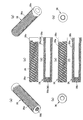
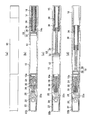
- 1 to 6 are explanatory views of a liquid material feeding container according to the first embodiment of the present invention.
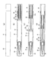
- FIG. 1 is an explanatory view of a liquid material supply container according to the first embodiment in a state where a cap is removed
- FIG. 2 is a state where the cap is removed.
- the liquid material supply container accommodates the liquid material in the accommodating portion 12 provided in the shaft main body 10, and the operation portion 16 of the rotating body 14 exposed from the rear end portion of the shaft main body 10.
- This is a liquid material supply container that advances the piston 18 in the accommodating portion 12 by rotating relative to the shaft body 10 and supplies the liquid material toward the application body 20 ahead of the shaft body 10.
- the tip 22 of the shaft body 10 is detachable from the cap 22, and when the liquid material supply container is not used, the tip 22 is covered by the cap 22 as shown in FIG. In use, the cap 22 is removed and the applicator 20 is fed out.
- the liquid material supply container has a seal ball receiver 24, a pipe joint 26, a pipe 28, a tip shaft 30, and an application body 20 attached to the tip portion 10 a of the shaft body 10.
- the delivered liquid material is discharged to the tip of the application body 20 through the pipe 28.
- the tip portion 10a of the shaft body 10 has a diameter that is thinner than the central portion, and a cylindrical seal ball receiver 24 is fitted inside the tip portion 10a.
- a seal ball (not shown) is fitted in the rear part of the seal ball receiver 24, and a pipe joint 26 is attached to the front part.
- a pipe 28 is attached to the pipe joint 26 in the front, and the pipe 28 is inserted into the application body 20 made of a brush from the rear part.
- the hollow communication paths of the pipe joint 26 and the pipe 28 communicate with the application body 20, and when the seal ball is fitted in the seal ball receiver 24, the communication between the hollow communication path and the housing portion 12 is closed by the seal ball. .
- the seal ball receiver 24 is provided with a seal ball locking structure (not shown). When the seal ball receiver 24 is used, the seal ball is dropped into the housing portion 12 by removing the lock structure, and the liquid material passes through the pipe joint 26 and the pipe 28. So as to be supplied to the application body 20.
- the front shaft 30 covers the periphery of the pipe 28, the pipe joint 26 and the seal ball receiver 24 from the rear portion of the application body 20, and the front shaft 30 whose diameter is reduced in a tapered shape is fitted to the distal end portion 10 a of the shaft body 10.
- the inner peripheral surface of the tip shaft 30 and the outer peripheral surface of the distal end portion 10a of the shaft body 10 are closely fitted to form a stopper (see FIGS. 1 and 2).
- the cap 22 including the inner cap 22a and the inner cap spring 22b can be attached.
- the cap 22 is mounted so as to cover the front shaft 30, and the inner cap 22a covers the periphery of the front shaft 30 and the application body 20 by the urging force of the inner cap spring 22b to maintain the airtightness of the application body 20. It is intended to prevent drying.
- the seal ball when the applicator is not used, the seal ball is fitted in the seal ball receiver 24, and when the use is started, the seal ball is dropped into the storage unit 12 so that the storage unit 12 and the pipe 28 are in a circulation state.
- bowl can be stirred by arrange
- the piston 18 has a seal portion 32 (outer periphery) at the front thereof in sliding contact with the inner wall of the accommodating portion 12 of the shaft body 10, and a rod member 34 having a screw portion on the inner periphery or outer periphery at the rear portion is movable in the axial direction. The rotation direction is restricted.
- the front rod-like portion 36 extending forward from the operation portion 16 is formed with a screw portion that is directly screwed with the screw portion of the rod member 34 at the rear portion of the piston 18.
- the front rod-like portion 36 of the rotating body 14 is provided with a thick cylindrical body that is screwed into the inside of the front portion of the operation portion 16 and extends forward, and this front rod-like portion.
- a threaded portion 38 (a threaded portion 38b of an internal thread) is formed on the threaded portion 36 of the rod member 34 at the rear portion of the piston 18.
- the front rod-like portion 36 that is screwed into the rotating body 14 is formed with screw portions 38 (a male screw portion 38a and a female screw portion 38b) on the inner and outer surfaces.
- screw portions 38 a male screw portion 38a on the outer peripheral surface screwed with the screw portion 14b made of the female screw is formed, and a female screw 38b screwed with the screw portion 34a of the bar member 34 is formed on the inner surface.
- a threaded portion 38 a made of an external thread on the outer periphery of the front rod-shaped portion 36 is formed continuously from the front end portion of the front rod-shaped portion 36 to the vicinity of the rear end portion.
- the rear end portion of the front bar-shaped portion 36 is a non-formed portion 38c where no thread is formed.
- a slit for dividing the screw may be formed in the screw portion 14b of the rotating body 14 (the slit portion 14c is formed in the screw portion 14b in a third embodiment described later (see FIG. 12). explain).
- the screw portion 14 b of the rotating body 14 (operation portion 16) is indirectly screwed to the screw portion 34 a of the rod member 34 via the screw portion 38 of the front rod-like portion 36. Yes.
- the sliding frictional force of the threaded portion 34a of the rod member 34 fixed to the piston 18 to the inner threaded portion 38b of the front rod-shaped portion 36 is such that the outer threaded portion 38a of the front rod-shaped portion 36 is a rotating body. It is set to be smaller than the sliding frictional force screwed into the 14 screw portions 14b.
- the rod member 34 of the piston 18 moves forward from the difference of the sliding frictional force by performing an operation of rotating relative to the shaft body 10 of the operation unit 16 from the state shown in FIG. 32 moves forward. Since the rod member 34 is locked to the front rod-like portion 36 in the state shown in FIG. 2 (c) after the piston 18 has moved forward, when the operation portion 16 is further rotated, the front rod-like portion 36 is attached to the rotating body 14.
- a structure that can be extended and contracted in multiple stages is provided by a mechanism that is extended and advanced to further advance the seal portion 32.
- the rotary body 14 is formed in the hollow and has opened the tail end, it is possible to improve the design by inserting a stopper so that the inside is not visible.
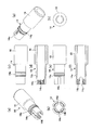
- the piston 18 has a structure in which the seal portion 32 and the rod member 34 are connected.
- the bar member 34 is a screw portion 34 a in which a thread is formed on the outer peripheral surface of substantially the entire central portion excluding the front end and the rear end.
- an engaging portion 34b with the seal portion 32 is formed in an irregular shape at the front end of the bar member 34, and a non-formed portion 34c in which no thread is formed is formed at the rear end.
- the engaging portion 34b is thin in the axial direction and is substantially shield-shaped.
- the seal portion 32 has a generally cup-shaped or wheel-shaped rotating body shape, and the front and rear ends of the outer peripheral surface thereof are formed to have a diameter larger than the center, and the outer peripheral surface has two circumferential directions.
- the seal surface formed along the slidable contact with the inner wall of the housing portion 12 of the shaft body 10 is configured.
- the seal portion 32 is formed such that an engaged portion 32a protrudes rearward in a cylindrical shape rearward from the internal hub-like portion.
- the engaged portion 32a is an engagement structure such as a hook structure in which a protruding cylindrical portion is formed with a cut on the side surface. From this cut, an engagement portion 34b (shown in FIG. 3) of the bar member 34 is formed. ) Is inserted and attached, the seal portion 32 and the rod member 34 are fixed in the rotational direction and the front-rear direction, and move back and forth as an integral piston 18.
- the rotating body 14 has a substantially hollow cylindrical shape, and the outer periphery has a larger diameter at the rear than the front, and is an operation unit 16 that can be picked and rotated by the user.
- An annular rib is formed on the outer peripheral surface of the front portion so as to have a fitting portion 14a that engages the shaft body 10 rotatably and prevents it from coming off.
- a screw portion 14b of a female screw is formed at the front.
- rod member 34 at the rear of the piston 18 is movable in the front-rear direction with respect to the inner wall of the accommodating portion 12 together with the seal portion 32 and is restricted in the rotational direction.
- the regulation of the rotational direction of the piston 18 is such that the outer peripheral surface of the seal portion 32 at the front portion of the piston 18 is in sliding contact with the inner wall of the housing portion 12 of the shaft body 10 and is movable in the axial direction. Is held so as not to be easily rotated by the sliding contact force. That is, the piston 18 is in sliding contact with an appropriate margin to prevent the liquid content from leaking when the front seal portion 32 is in sliding contact with the inner wall of the housing portion 12 of the shaft body 10. It is held so as not to be easily rotated in the circumferential direction by the sliding contact force generated by.
- Each part such as the piston 18 is resin-molded, and the tightening margin is adjusted by setting the dimensions thereof, and the material can be easily rotated by selecting a material.
- the threaded portion 34a of the rod member 34 fixed to the piston 18 is screwed into the inner threaded portion 38b of the front rod-shaped portion 36, and the outer threaded portion 38a of the front rod-shaped portion 36 is threaded to the threaded portion 14b of the rotating body. Match.
- the piston 18 is located at the retreat limit, and the accommodating portion 12 has the maximum volume.
- the operation unit 16 is picked and the rotating body 14 is rotated with respect to the shaft body 10.
- the rod member 34 of the piston 18 advances and the seal portion 32 advances due to the difference in the sliding frictional force. Go forward.
- the non-formed portion 34c without the threaded portion 34a comes into contact with the inner threaded portion 38b of the front rod-shaped portion 36, so that a fixed state with respect to the front rod-shaped portion 36 and a locked state where it does not advance further.
- the forward limit is shown in FIG.
- the outer male screw portion 38a is screwed with the female screw 14b of the rotating body 14, and therefore, as shown in FIG. Is fed to the rotating body 14 and moves forward to further advance the seal portion 32.
- the non-formed portion 38c of the screw portion 38 abuts against the female screw 14b of the rotating body 14, it does not advance any further, and the piston 18 can be prevented from being pushed too much.
- the liquid material delivery container is configured such that the rod member 34 and the front rod-like portion 36 of the piston 18 can be expanded and contracted in multiple stages with respect to the rotating body 14.
- the present invention is not limited to the configuration of the liquid material supply container according to the first embodiment, and can be variously modified.
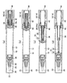
- a liquid material supply container according to a second embodiment of the present invention will be described with reference to FIGS.
- the same parts as those in the first embodiment are denoted by the same reference numerals.
- the piston 18 is formed by integrally resin-molding the front seal part 32 and the rear bar member 34. Since the rod member 34 having a threaded portion on the outer periphery is integral, it can be moved in the axial direction like the piston 18 and is restricted in the rotational direction.
- the non-formed part 34c is not formed with a screw, and therefore, when assembled to the front rod-like part 36, a slit is formed in the female screw 38b so as to be divided or not formed.
- the part 34c may have a slit, or both may have a slit.
- the application body 20 has a substantially conical shape, and a plurality of disk portions (flange-like portions) protruding outward are concentrically arranged at predetermined intervals from the front end to the rear end.
- the application body 20 is used to apply a liquid such as mascara, and has a structure that can be easily applied to the eyelashes or the like by the protrusions of the disk portion and can be sufficiently applied.
- the periphery of the application body 20 is covered with a tip shaft and fitted into the tip portion 10 a of the shaft body 10.
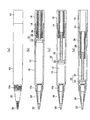
- FIGS. 10 is a non-use state in which a cap is provided
- FIG. 11 is a use state in which the cap is removed
- FIG. 12 is an explanatory view of a rotating body
- FIG. 13 is a vertical cross-sectional explanatory view of a rear portion of a liquid material supply container.
- the piston 18 has a structure in which the seal portion 32 and the rod member 34 are connected in the same manner as in the first embodiment. Further, as shown in FIG. 10, the cap 22 is fitted when not in use, and the cap 22 is removed when in use as shown in FIG. Before the piston 18 is extended, the state shown in FIG. 10A and FIG. 11A is obtained. Before the piston 18 is extended, the state shown in FIG. 10B and FIG. The limit is as shown in FIG. 10 (c) and FIG. 11 (c).
- the rotating body 14 has a substantially hollow cylindrical shape, the outer periphery is larger in the rear than the front, and the operation unit 16 that can be picked and rotated by the user. It has become.
- a rib is formed on the outer peripheral surface of the front portion in an annular shape of a fitting portion 14a that rotatably engages and prevents the shaft body 10 from coming off.
- a screw portion 14b of a female screw is formed at the front portion.
- a slit for dividing the screw portion is provided at one end of the front rod-like portion of the rotating body 14.
- segments the screw part 14b is formed in the part ahead of the one part operation part 16 of the rotary body 14 at the part to which the front bar-shaped part 36 is screwed. That is, a slit 14c is formed in the front portion of the rotating body 14 by cutting backward from the front end so as to cut the formation portion of the screw portion 14b at two pairs of radial positions.
- the front portion of the rotating body 14 is slightly enlarged in diameter from the slit 14c when the front rod member 36 is assembled, and the front rod-like portion 36 can be gently screwed. Further, it is possible to press-fit the front bar member 36 as it is by expanding the diameter from the slit 14c.
- the slit 14c can be provided close to the inner peripheral surface (indicated by reference numeral 10b) of the shaft body 10.
- interval (delta) of the slit 14c and the internal peripheral surface 10b is 0.5 mm or less. This interval can be selected and implemented as appropriate.
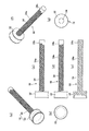
- a liquid material supply container according to the fourth embodiment of the present invention will be described with reference to FIG.
- the same parts as those in the first embodiment are denoted by the same reference numerals.
- this liquid material supply container is provided with a rear cylinder member 40 that is screwed into the outer periphery of the front bar-like portion 36 and screwed into the inner periphery of the screw portion 14 b of the rotating body 14.
- An elastic body (spring) 42 is provided between the front bar portion 36 and the rotating body 14.
- This liquid material supply container has a structure in which the elastic body 42 urges the front rod-shaped portion 36 forward, so that as shown in FIGS.
- the piston 18 can be advanced not only by the forward force but also by the forward force via the front rod-like portion 36 by the pressing force of the projectile 42.
- a substantially cup-shaped spring that is open at the front and closed at the rear to receive the rear end of the elastic body 42 in the roughly cylindrical rotating body 14.
- a receiver 44 is provided so as to close the rear opening of the rotating body 14.
- a rear cylindrical member 40 is disposed coaxially between the rotating body 14 and the front bar-shaped portion 36.
- the rear cylinder member 40 has screws (internal and external threads) formed on the inner and outer peripheral surfaces.
- a male screw is formed on the outer peripheral surface over the front and back, and a female screw is formed on the inner peripheral surface with a small front portion, and a rear portion from the rear end of the female screw via a stepped portion. Then, the diameter is increased and formed on a flat inner surface without screws.
- the inner thread portion 14b of the rotating body 14 is screwed into the outer thread of the rear cylindrical member 40, and the outer male thread 38a of the front rod-shaped portion 36 is The member 40 is screwed into the female screw on the inner peripheral surface.
- the piston 18 is configured such that the front seal portion 32 is coupled to the front end of the rear rod portion 34 by screwing a screw inserted from the front.
- the piston 18 may have a structure in which a seal portion 32 and a rod-like portion 34 are coupled as shown in FIG. 1 which is the first embodiment and FIG. 10 which is the third embodiment. Or it is good also as a structure with which the seal
- the rear portion of the rear cylinder member 40 is provided so that a spring 42 accommodated in the spring receiver 44 can be received and presses the rear cylinder member 40 forward.
- the feeding torque to the piston 18 can be applied by the pressing force of the elastic body 42 together with the rotational force of the rotating body 14.
- the coating liquid can be applied with a light rotational force. This is because, when the outer diameter of the screw of the rotating body 14 is increased without the rear cylindrical member 40 and the elastic body 42 being provided, the inner diameter of the screw portion 14b of the rotating body 14 and the front rod-like portion 36 that is screwed to the inner diameter.
- the user can quickly feed out the contents with a smaller number of rotary feeding operations when starting to use, and the feeding operation can be rotated by increasing the screw pitch.
- the force increases, the liquid material can be quickly delivered with a light force by the assistance of the projectile 42.
- the two-stage piston 18 can be driven forward and forward by the rod member 34, the front rod-shaped portion 36, and the rotating body 14. It is also possible to provide a plurality of front bar portions so that they can be driven out in three or more stages.
- the rod member, the front rod-shaped portion, the male thread of the threaded part of the rotating body, and the female thread can be set to other settings.
- a structure can be adopted in which a rod member is hollowed and a front rod-like portion is screwed therein, and a rod-like male screw is screwed into the front rod-like portion from a rotating body.
- liquid materials such as oral cleansing agents, drugs, etc. are accommodated in the accommodating portion of the shaft body, and are accommodated by a feeding operation that rotates the tail end.
- SYMBOLS 10 Shaft main body 10a Tip part 12 Storage part 14 Rotating body 14a Fit part 14b Screw part 16 Operation part 18 Piston 18b Engagement part 20 Application body 22 Cap 30 Lead shaft 32 Seal part 32a Engagement part 34 Bar member 34a Screw Part 34b engaging part 34c non-forming part 36 front rod-like part 38 screw part 38a outer male screw 38b inner female screw 40 rear cylinder member 42 elastic body
Landscapes
- Containers And Packaging Bodies Having A Special Means To Remove Contents (AREA)
- Pens And Brushes (AREA)
Priority Applications (2)
| Application Number | Priority Date | Filing Date | Title |
|---|---|---|---|
| US14/769,659 US9924777B2 (en) | 2013-02-25 | 2014-02-25 | Liquid substance advancing container |
| EP14753988.6A EP2959794B1 (de) | 2013-02-25 | 2014-02-25 | Behälter zur ausgabe einer flüssigen substanz |
Applications Claiming Priority (4)
| Application Number | Priority Date | Filing Date | Title |
|---|---|---|---|
| JP2013-034730 | 2013-02-25 | ||
| JP2013034730 | 2013-02-25 | ||
| JP2014-029446 | 2014-02-19 | ||
| JP2014029446A JP6424005B2 (ja) | 2013-02-25 | 2014-02-19 | 液状物繰出容器 |
Publications (1)
| Publication Number | Publication Date |
|---|---|
| WO2014129645A1 true WO2014129645A1 (ja) | 2014-08-28 |
Family
ID=51391421
Family Applications (1)
| Application Number | Title | Priority Date | Filing Date |
|---|---|---|---|
| PCT/JP2014/054430 Ceased WO2014129645A1 (ja) | 2013-02-25 | 2014-02-25 | 液状物繰出容器 |
Country Status (4)
| Country | Link |
|---|---|
| US (1) | US9924777B2 (de) |
| EP (1) | EP2959794B1 (de) |
| JP (1) | JP6424005B2 (de) |
| WO (1) | WO2014129645A1 (de) |
Cited By (1)
| Publication number | Priority date | Publication date | Assignee | Title |
|---|---|---|---|---|
| CN106793861A (zh) * | 2014-10-08 | 2017-05-31 | 衍宇株式会社 | 按钮型笔式化妆品容器 |
Families Citing this family (1)
| Publication number | Priority date | Publication date | Assignee | Title |
|---|---|---|---|---|
| CN205658538U (zh) * | 2016-05-31 | 2016-10-26 | 洽兴包装工业(中国)有限公司 | 大容量化妆笔 |
Citations (6)
| Publication number | Priority date | Publication date | Assignee | Title |
|---|---|---|---|---|
| JPS633311U (de) * | 1986-06-23 | 1988-01-11 | ||
| JP2004160117A (ja) * | 2002-11-11 | 2004-06-10 | Masayuki Kuzuu | 口紅等が全て使い切る事ができる口紅等の収納容器 |
| JP2007130438A (ja) * | 2005-10-12 | 2007-05-31 | Tokiwa Corp | 充填物押出容器 |
| JP2007143857A (ja) | 2005-11-28 | 2007-06-14 | Tokiwa Corp | 内容物押出容器 |
| JP2008043590A (ja) * | 2006-08-18 | 2008-02-28 | Tokiwa Corp | 充填物押出容器 |
| JP2010227553A (ja) | 2009-03-03 | 2010-10-14 | Mitsubishi Pencil Co Ltd | 液状物繰出容器 |
Family Cites Families (13)
| Publication number | Priority date | Publication date | Assignee | Title |
|---|---|---|---|---|
| JPS633311A (ja) | 1986-06-23 | 1988-01-08 | Toshiba Corp | 三次元位置検出装置 |
| US5100252A (en) * | 1990-07-02 | 1992-03-31 | Grigory Podolsky | Toothbrush |
| JP2736039B2 (ja) * | 1994-08-25 | 1998-04-02 | 株式会社トキワ | 化粧料繰り出し容器 |
| FR2825904B1 (fr) * | 2001-06-15 | 2004-07-09 | Oreal | Stick, notamment pour un produit sous forme d'une creme, d'un gel, ou d'une pate |
| WO2005046423A1 (en) * | 2003-11-13 | 2005-05-26 | Unilever Plc | Fabric cleaning fluid and dispensing device |
| JP4739847B2 (ja) * | 2005-07-28 | 2011-08-03 | 株式会社トキワ | 充填物押出容器 |
| EP1769698A1 (de) * | 2005-09-30 | 2007-04-04 | OEKAMETALL OEHLHORN GmbH & Co. KG | Behälter zum Auftragen von Kosmetika, insbesondere Lippenpomade, vorzugsweise in Stiftform |
| US8172472B2 (en) * | 2007-11-08 | 2012-05-08 | Tokiwa Corporation | Stick-shaped material extruding container |
| US8104984B2 (en) * | 2007-12-14 | 2012-01-31 | Tokiwa Corporation | Filled material extruding container |
| JP2009247427A (ja) * | 2008-04-02 | 2009-10-29 | Mitsubishi Pencil Co Ltd | 回転式繰出容器 |
| JP5545681B2 (ja) * | 2009-03-03 | 2014-07-09 | 三菱鉛筆株式会社 | 液状物繰出容器 |
| JP5467952B2 (ja) * | 2010-07-07 | 2014-04-09 | 三菱鉛筆株式会社 | 塗布具 |
| KR101259431B1 (ko) * | 2011-07-26 | 2013-04-30 | (주)연우 | 펜슬형 화장품 용기 |
-
2014
- 2014-02-19 JP JP2014029446A patent/JP6424005B2/ja not_active Expired - Fee Related
- 2014-02-25 EP EP14753988.6A patent/EP2959794B1/de not_active Not-in-force
- 2014-02-25 US US14/769,659 patent/US9924777B2/en not_active Expired - Fee Related
- 2014-02-25 WO PCT/JP2014/054430 patent/WO2014129645A1/ja not_active Ceased
Patent Citations (6)
| Publication number | Priority date | Publication date | Assignee | Title |
|---|---|---|---|---|
| JPS633311U (de) * | 1986-06-23 | 1988-01-11 | ||
| JP2004160117A (ja) * | 2002-11-11 | 2004-06-10 | Masayuki Kuzuu | 口紅等が全て使い切る事ができる口紅等の収納容器 |
| JP2007130438A (ja) * | 2005-10-12 | 2007-05-31 | Tokiwa Corp | 充填物押出容器 |
| JP2007143857A (ja) | 2005-11-28 | 2007-06-14 | Tokiwa Corp | 内容物押出容器 |
| JP2008043590A (ja) * | 2006-08-18 | 2008-02-28 | Tokiwa Corp | 充填物押出容器 |
| JP2010227553A (ja) | 2009-03-03 | 2010-10-14 | Mitsubishi Pencil Co Ltd | 液状物繰出容器 |
Non-Patent Citations (1)
| Title |
|---|
| See also references of EP2959794A4 * |
Cited By (2)
| Publication number | Priority date | Publication date | Assignee | Title |
|---|---|---|---|---|
| CN106793861A (zh) * | 2014-10-08 | 2017-05-31 | 衍宇株式会社 | 按钮型笔式化妆品容器 |
| EP3228211A4 (de) * | 2014-10-08 | 2018-07-11 | Yonwoo Co.,Ltd | Knopfstiftspender für kosmetika |
Also Published As
| Publication number | Publication date |
|---|---|
| EP2959794A4 (de) | 2016-10-12 |
| US20160007715A1 (en) | 2016-01-14 |
| JP6424005B2 (ja) | 2018-11-14 |
| EP2959794B1 (de) | 2020-12-09 |
| EP2959794A1 (de) | 2015-12-30 |
| JP2014184135A (ja) | 2014-10-02 |
| US9924777B2 (en) | 2018-03-27 |
Similar Documents
| Publication | Publication Date | Title |
|---|---|---|
| JP5545632B2 (ja) | 液状物繰出容器 | |
| JP5108919B2 (ja) | 充填物押出容器 | |
| JP6818311B2 (ja) | 塗布容器及び塗布容器の製造方法 | |
| US9862225B2 (en) | Liquid applying tool | |
| KR101579643B1 (ko) | 노크식 도포구 | |
| JP6600489B2 (ja) | 回転繰出容器 | |
| JP6045127B2 (ja) | 塗布具 | |
| US6957753B2 (en) | Movable body feeding apparatus | |
| JP6424005B2 (ja) | 液状物繰出容器 | |
| JP7394199B2 (ja) | 化粧料塗布具 | |
| JP2022190935A (ja) | 棒状物繰出容器 | |
| JP6700676B2 (ja) | 回転繰出容器 | |
| CN106660064A (zh) | 用于多筒管的转动式配制器 | |
| JP4939334B2 (ja) | 塗布材押出容器 | |
| KR20180046931A (ko) | 펜타입 화장품 용기 | |
| JP5610775B2 (ja) | 液体塗布具 | |
| JP2007330814A5 (de) | ||
| JP6001416B2 (ja) | 繰出し容器 | |
| JP5545681B2 (ja) | 液状物繰出容器 | |
| EP1698251B1 (de) | Behälter für stiftförmige Kosmetika | |
| JP2023013700A (ja) | カートリッジ式化粧料押出容器 | |
| JP5234596B2 (ja) | ノック式繰出容器 | |
| JP2017113163A (ja) | 塗布具 | |
| JP6262466B2 (ja) | 固形棒状化粧料容器 | |
| JP7145478B2 (ja) | 棒状化粧料繰出容器 |
Legal Events
| Date | Code | Title | Description |
|---|---|---|---|
| 121 | Ep: the epo has been informed by wipo that ep was designated in this application |
Ref document number: 14753988 Country of ref document: EP Kind code of ref document: A1 |
|
| WWE | Wipo information: entry into national phase |
Ref document number: 14769659 Country of ref document: US |
|
| NENP | Non-entry into the national phase |
Ref country code: DE |
|
| WWE | Wipo information: entry into national phase |
Ref document number: 2014753988 Country of ref document: EP |