WO2014132396A1 - Dispositif de conversion de puissance - Google Patents
Dispositif de conversion de puissance Download PDFInfo
- Publication number
- WO2014132396A1 WO2014132396A1 PCT/JP2013/055435 JP2013055435W WO2014132396A1 WO 2014132396 A1 WO2014132396 A1 WO 2014132396A1 JP 2013055435 W JP2013055435 W JP 2013055435W WO 2014132396 A1 WO2014132396 A1 WO 2014132396A1
- Authority
- WO
- WIPO (PCT)
- Prior art keywords
- current
- converter
- current limiting
- power
- line
- Prior art date
- Legal status (The legal status is an assumption and is not a legal conclusion. Google has not performed a legal analysis and makes no representation as to the accuracy of the status listed.)
- Ceased
Links
Images










Classifications
-
- H—ELECTRICITY
- H02—GENERATION; CONVERSION OR DISTRIBUTION OF ELECTRIC POWER
- H02H—EMERGENCY PROTECTIVE CIRCUIT ARRANGEMENTS
- H02H7/00—Emergency protective circuit arrangements specially adapted for specific types of electric machines or apparatus or for sectionalised protection of cable or line systems, and effecting automatic switching in the event of an undesired change from normal working conditions
- H02H7/26—Sectionalised protection of cable or line systems, e.g. for disconnecting a section on which a short-circuit, earth fault, or arc discharge has occured
- H02H7/268—Sectionalised protection of cable or line systems, e.g. for disconnecting a section on which a short-circuit, earth fault, or arc discharge has occured for DC systems
-
- H—ELECTRICITY
- H02—GENERATION; CONVERSION OR DISTRIBUTION OF ELECTRIC POWER
- H02H—EMERGENCY PROTECTIVE CIRCUIT ARRANGEMENTS
- H02H9/00—Emergency protective circuit arrangements for limiting excess current or voltage without disconnection
- H02H9/02—Emergency protective circuit arrangements for limiting excess current or voltage without disconnection responsive to excess current
-
- H—ELECTRICITY
- H02—GENERATION; CONVERSION OR DISTRIBUTION OF ELECTRIC POWER
- H02J—ELECTRIC POWER NETWORKS; CIRCUIT ARRANGEMENTS OR SYSTEMS FOR SUPPLYING OR DISTRIBUTING ELECTRIC POWER; SYSTEMS FOR STORING ELECTRIC ENERGY
- H02J3/00—Circuit arrangements for AC mains or AC distribution networks
- H02J3/36—Arrangements for transfer of electric power between AC networks via high-voltage DC [HVDC] links; Arrangements for transfer of electric power between generators and networks via HVDC links
-
- H—ELECTRICITY
- H02—GENERATION; CONVERSION OR DISTRIBUTION OF ELECTRIC POWER
- H02H—EMERGENCY PROTECTIVE CIRCUIT ARRANGEMENTS
- H02H9/00—Emergency protective circuit arrangements for limiting excess current or voltage without disconnection
- H02H9/001—Emergency protective circuit arrangements for limiting excess current or voltage without disconnection limiting speed of change of electric quantities, e.g. soft switching on or off
-
- Y—GENERAL TAGGING OF NEW TECHNOLOGICAL DEVELOPMENTS; GENERAL TAGGING OF CROSS-SECTIONAL TECHNOLOGIES SPANNING OVER SEVERAL SECTIONS OF THE IPC; TECHNICAL SUBJECTS COVERED BY FORMER USPC CROSS-REFERENCE ART COLLECTIONS [XRACs] AND DIGESTS
- Y02—TECHNOLOGIES OR APPLICATIONS FOR MITIGATION OR ADAPTATION AGAINST CLIMATE CHANGE
- Y02E—REDUCTION OF GREENHOUSE GAS [GHG] EMISSIONS, RELATED TO ENERGY GENERATION, TRANSMISSION OR DISTRIBUTION
- Y02E60/00—Enabling technologies; Technologies with a potential or indirect contribution to GHG emissions mitigation
- Y02E60/60—Arrangements for transfer of electric power between AC networks or generators via a high voltage DC link [HVCD]
Definitions
- the present invention relates to a power conversion device applied to a DC power transmission system in which a plurality of power supply systems are connected by DC lines.
- Self-excited DC power transmission using self-excited converters can be installed in weak systems and locations where there is no AC power supply, and has the advantage of easy configuration of DC systems between multiple terminals.
- the application is also expanding.
- DC transmission system In such a self-excited DC transmission system (hereinafter simply referred to as “DC transmission system”), if there is no means to suppress the short-circuit current when a ground fault or short-circuit accident occurs in the DC main circuit, an excessive accident will occur. There is a risk that the current flows to a device such as an AC / DC converter connected to the system. For this reason, in order to remove the accident current at the time of an accident on the DC line and protect the system equipment, for example, it is conceivable to introduce a DC circuit breaker, but if an excessive accident current is to be interrupted by the DC circuit breaker, There is a problem that the equipment becomes larger and more expensive.
- a current limiting element and a freewheeling diode are connected in parallel, and in normal times, a forward current flows through the freewheeling diode.
- the technique to do is disclosed (for example, patent document 1).
- the present invention has been made in view of the above, and in a DC power transmission system interconnected by connecting a plurality of power supply systems with a DC line, downsizing of facilities by suppressing an accident current at the time of an accident, It aims at providing the power converter device which can suppress the energization loss at the time of performing DC power transmission, aiming at cost reduction.
- a power conversion device is a power conversion device applied to a DC power transmission system interconnected by connecting a plurality of power supply systems with a DC line.
- a current-limiting circuit comprising a converter that performs power conversion between the power supply system and the DC power transmission system, and a current-limiting element and a switching device connected in parallel to the current-limiting element,
- a circuit is provided between the converter and the DC line, and when the current flowing through the converter exceeds a threshold lower than an allowable current upper limit value of the converter, the switching device is controlled to open. It is characterized by that.
- a DC power transmission is performed while suppressing an accident current at the time of an accident and reducing the size and cost of the equipment.
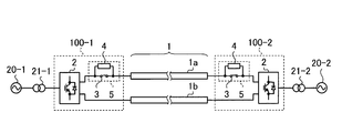
- FIG. 1 is a diagram illustrating an example of a two-terminal DC power transmission system to which the power conversion device according to the first embodiment is applied.
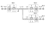
- FIG. 2 is a diagram illustrating an example of a non-loop multi-terminal DC power transmission system to which the power conversion device according to the first embodiment is applied.
- FIG. 3 is a diagram for explaining an operation example of the current limiting circuit of the power conversion device according to the first embodiment in the non-loop type multi-terminal DC power transmission system shown in FIG. 2.
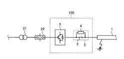
- FIG. 4 is a diagram illustrating a configuration example in which an AC circuit breaker is provided in the previous stage of the power conversion device according to the first embodiment.
- FIG. 5 is a diagram showing an example of an accident current interruption operation in the configuration shown in FIG. FIG.
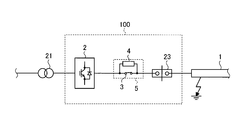
- FIG. 6 is a diagram illustrating a configuration example in which the power converter according to the first embodiment includes a DC circuit breaker.
- FIG. 7 is a diagram illustrating an example of an accident current interruption operation in the configuration illustrated in FIG. 6.
- FIG. 8 is a diagram illustrating an example in which the opening / closing device includes a mechanical opening / closing element in the power conversion device according to the first embodiment.
- FIG. 9 is a diagram illustrating an example in which the mechanical switching element and the semiconductor switch element are connected in series in the power conversion device according to the first embodiment.
- FIG. 10 is a diagram illustrating an example in which the current limiting element is configured by a reactor in the power conversion device according to the first embodiment.
- FIG. 11 is a diagram illustrating an example in which the current limiting element is configured with a resistor in the power conversion device according to the first embodiment.
- FIG. 12 is a diagram illustrating an example in which the current limiting element is configured with a superconducting current limiter in the power conversion device according to the first embodiment.
- FIG. 13 is a diagram illustrating an example in which the current limiting element is configured with a saturable reactor in the power conversion device according to the first embodiment.
- FIG. 14 is a diagram illustrating an example in which the current limiting element is configured by a semiconductor switch element in the power conversion device according to the first embodiment.
- FIG. 15 is a diagram of an example of a multi-line DC power transmission system to which the power conversion device according to the first embodiment is applied.
- FIG. 16 is a diagram illustrating an example of a loop-type multi-terminal DC power transmission system to which the power conversion device according to the first embodiment is applied.
- FIG. 17 is a diagram illustrating an example different from FIG. 16 of the loop-type multi-terminal DC power transmission system to which the power conversion device according to the first embodiment is applied.
- FIG. 18 is a diagram illustrating an example different from FIG. 1 of the two-terminal DC power transmission system to which the power conversion device according to the first embodiment is applied.
- FIG. 19 is a diagram illustrating an example different from FIG. 2 of the non-loop type multi-terminal DC power transmission system to which the power conversion device according to the first embodiment is applied.
- FIG. 20 is a diagram illustrating an example different from FIGS.
- FIG. 21 is a diagram illustrating an example of a two-terminal DC power transmission system having a neutral wire to which the power conversion device according to the second embodiment is applied.
- FIG. 22 is a diagram illustrating an example of a two-terminal DC power transmission system that does not have a neutral wire to which the power conversion device according to the second embodiment is applied.
- FIG. 23 is a diagram illustrating an example of a two-terminal DC power transmission system having a positive line, a negative line, and a neutral line to which the power conversion device according to the second embodiment is applied.
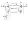
- FIG. 1 is a diagram illustrating an example of a two-terminal DC power transmission system to which the power conversion device according to the first embodiment is applied.
- an example is applied to a two-terminal DC transmission system in which a plurality of power supply systems 20-1 and 20-2 are connected by a DC line 1 composed of a positive electrode line 1a and a negative electrode line 1b. Show.
- a power converter 100-1 is connected to the left end side of the DC line 1 with a power supply system 20-1 via a transformer 21-1, and on the right end side of the DC line 1. Is connected to the power supply system 20-2 through the transformer 21-2.
- Each of the power conversion devices 100-1 and 100-2 includes a converter 2 that performs power conversion between the power supply systems 20-1 and 20-2 and a DC transmission system including the DC line 1, a converter 2 and a DC
- a current limiting circuit 5 provided between the line 1 and including a current limiting element 4 and a switching device 3 connected in parallel to the current limiting element 4 is provided.
- the power supply systems 20-1 and 20-2 are AC power supply systems and the converter 2 is an AC-DC converter, but the power supply systems 20-1 and 20- 2 may be a distributed power system such as a DC power source such as solar power generation or a power storage element. In this case, the converter 2 may be a DC-DC converter.
- the switchgear 3 was equipped at the both ends of the negative electrode wire 1b or both ends of the positive electrode wire 1a and the negative electrode wire 1b. It may be the configuration.
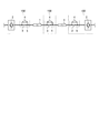
- FIG. 2 is a diagram illustrating an example of a non-loop multi-terminal DC power transmission system to which the power conversion device according to the first embodiment is applied.
- the positive line 1a and the negative line 1b are not distinguished from each other, and simply the DC line 1 (1-1, 1--1 when there are a plurality of DC lines). 2, 1-3, and so on), and in the text of the first embodiment, the DC line 1 will be similarly described.
- the power supply system 20 (20-1, 20-2 if there are a plurality of power supply systems), the transformer 21 (if there are a plurality of transformers, 21- 1, 21-2,..., And power converter 100 (in the case where there are a plurality of power converters, 100-1, 100-2,...) are described and explained.
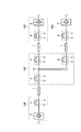
- FIG. 3 is a diagram for explaining an operation example of the current-limiting circuit of the power conversion device according to the first embodiment in the non-loop multi-terminal DC power transmission system shown in FIG.
- the horizontal axis indicates time
- the vertical axis indicates the current flowing through the converter 2.
- FIG. 3A shows the behavior of the current flowing through the converter 2 of the power conversion device 100-1
- FIG. 3B shows the behavior of the current flowing through the converter 2 of the power conversion device 100-2
- FIG. 3C shows the behavior of the current flowing through the converter 2 of the power conversion device 100-3.
- FIG. 2 shows a non-loop type multi-terminal DC transmission system that branches into DC lines 1-1, 1-2, 1-3 at a branch point A.
- the opening / closing device 3 is closed and short-circuited. Since the current limiting element 4 has an impedance, a steady current flows through the switching device 3, and no current flows through the current limiting element 4.
- a threshold for the current flowing through the converter 2 is set as a trigger for controlling the opening and closing of the switchgear 3, and when the current flowing through the converter 2 exceeds this threshold, the switchgear 3 Is controlled to be opened and commutated to the current limiting element 4.
- this threshold value is set to a value lower than the allowable current upper limit value of the converter 2, when an accident occurs in the DC line 1, the accident current flowing through the converter 2 is suppressed, and an AC circuit breaker or a DC that will be described later is suppressed.
- the current flowing through the converter 2 is prevented from exceeding the allowable current upper limit value of the converter 2 until the current is interrupted by the circuit breaker.
- the power converter (100-2, 100-3 here) connected to a healthy DC line here, DC lines 1-2, 1-3
- the operation can be continued without performing the open control, that is, without causing a power transmission loss due to the current limiting element 4.
- FIG. 4 is a diagram illustrating a configuration example in which an AC circuit breaker is provided in the previous stage of the power conversion apparatus according to the first embodiment.
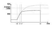
- FIG. 5 is a diagram showing an example of an accident current interruption operation in the configuration shown in FIG. In FIG. 5, the horizontal axis represents time, and the vertical axis represents the current flowing through the converter 2. Also, the solid line shown in FIG. 5 shows the current behavior in the configuration of the first embodiment provided with the current limiting circuit 5, and the broken line shows the current behavior when the current limiting circuit 5 is not provided.
- the current value at the time when current interruption is performed by the AC breaker 22 by connecting the current limiting circuit 5 between the converter 2 and the DC line 1 (time t ⁇ b> 2 shown in FIG. 5). Can be suppressed. That is, since the current interrupting duty of the AC circuit breaker 22 can be reduced as compared with the conventional configuration without the current limiting circuit 5, the AC circuit breaker 22 can be reduced in size and cost.
- the operation time of a mechanical AC circuit breaker that is generally used is about 50 ms to 100 ms, in the conventional configuration that does not include the current limiting circuit 5, current interruption is performed from the occurrence of an accident (time t0 shown in FIG. 5). Until (time t2 shown in FIG. 5), the accident current may exceed the allowable current upper limit value of the converter 2 (broken line in FIG. 5).
- the opening / closing device 3 is controlled to open and commutated to the current limiting element 4, and therefore flows to the converter 2.
- the time until the current exceeds the allowable current upper limit value of the converter 2 can be increased. That is, it is possible to prevent the current flowing through the converter 2 from exceeding the allowable current upper limit value of the converter 2 by time t2 when current interruption is performed by the AC circuit breaker 22 (solid line in FIG. 5).
- FIG. 6 is a diagram illustrating a configuration example in which the power converter according to the first embodiment includes a DC circuit breaker.
- FIG. 7 is a diagram showing an example of an accident current interruption operation in the configuration shown in FIG. In FIG. 7, the horizontal axis indicates time, and the vertical axis indicates the current flowing through the converter 2. Further, the solid line shown in FIG. 7 shows the current behavior in the configuration of the first embodiment provided with the current limiting circuit 5, and the broken line shows the current behavior when the current limiting circuit 5 is not provided.
- the current limiting circuit 5 is connected in series to the DC breaker 23, thereby suppressing the current value at the time when the current breaker is performed by the DC breaker 23 (time t ⁇ b> 3 shown in FIG. 7). Can do.
- the current interrupt duty of the DC circuit breaker 23 can be reduced as compared with the conventional configuration that does not include the current limiting circuit 5, and therefore the DC circuit breaker 23 can be reduced in size and cost.
- the opening / closing device 3 is controlled to open and commutated to the current limiting element 4, and therefore flows to the converter 2.
- the time until the current exceeds the allowable current upper limit value of the converter 2 can be increased. That is, it is possible to prevent the current flowing through the converter 2 from exceeding the allowable current upper limit value of the converter 2 by the time t3 when the current interruption is performed by the DC circuit breaker 23 (solid line in FIG. 7).
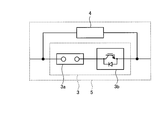
- FIG. 8 is a diagram illustrating an example in which the switchgear is configured by mechanical switch elements in the power conversion device according to the first embodiment.
- FIG. 9 is a diagram illustrating an example in which, in the power conversion device according to the first embodiment, the switchgear is configured by connecting mechanical switchgear elements and semiconductor switch elements in series.
- the switchgear 3 As shown in FIG. 8, by configuring the switchgear 3 with a circuit breaker, a disconnector, or a mechanical switching element 3a including a switch, it is possible to extremely reduce energization loss when performing normal DC power transmission. It is.
- the mechanical switching element 3a with a GCB (Gas Circuit Breaker), it is possible to have a configuration that can withstand overvoltage when the GCB is opened.
- GCB Gate Circuit Breaker
- a low-rated (for example, 4.5 kV / 1200 A) semiconductor switch element 3b with low conduction loss is connected in series with the mechanical switching element 3a in the same manner as the mechanical switching element 3a.
- the mechanical switching element 3a is controlled to be opened after the semiconductor switching element 3b is turned off.
- the duty can be limited to the voltage interruption duty, and the mechanical switching element 3a can be constituted by an inexpensive switch or disconnector.
- the semiconductor switch element 3b is configured by an IGBT (Insulated Gate Bipolar Transistor: Insulated Gate Bipolar Transistor) or a GCT thyristor (Gate Commutated Turn-off Thyristor: gate commutation type turn-off thyristor) capable of high-speed operation.
- IGBT Insulated Gate Bipolar Transistor
- GCT thyristor Gate Commutated Turn-off Thyristor: gate commutation type turn-off thyristor
- FIG. 10 is a diagram illustrating an example in which the current limiting element is configured by a reactor in the power conversion device according to the first embodiment.
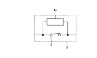
- FIG. 11 is a diagram illustrating an example in which the current limiting element is configured by a resistor in the power conversion device according to the first embodiment.
- FIG. 12 is a diagram illustrating an example in which the current limiting element is configured with a superconducting current limiter in the power conversion device according to the first embodiment.
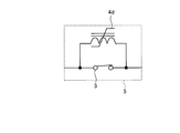
- FIG. 13 is a diagram illustrating an example in which the current limiting element is configured by a saturable reactor in the power conversion device according to the first embodiment.
- FIG. 14 is a diagram illustrating an example in which the current limiting element is configured by a semiconductor switch element in the power conversion device according to the first embodiment.
- the superconducting current limiter 4c when the current limiting element 4 is composed of a superconducting current limiter 4c, during normal operation in which normal DC power transmission is performed, the superconducting current limiter 4c is set in a superconducting state to have a low impedance, After the fault current commutates to this superconducting fault current limiter 4c at the time of opening 3 (time t1 'shown in FIG. 5 and FIG. 7), the superconducting fault limiter 4c is transferred to the quenching state to have a high impedance. Thus, the accident current flowing through the converter 2 is suppressed. That is, the fault current can be easily commutated while the superconducting current limiter 4c is in a low impedance state.
- the superconducting fault current limiter 4c is set in a normal conduction state to be in a high impedance state, and the occurrence of an accident in the DC line 1 is detected so that the superconducting fault current limiter 4c is set in a superconducting state to have a low impedance. By doing so, it is not necessary to keep the superconducting fault current limiter 4c in a superconducting state during steady operation, and therefore it is possible to prevent unnecessary energy loss.
- the saturable reactor 4 d is set in a saturated state to have a low impedance, and the switchgear 3
- the accident current is commutated to the saturable reactor 4d at the time of opening (time t1 'shown in FIGS. 5 and 7)
- the accident that flows into the converter 2 by setting the saturable reactor 4d to the unsaturated state and setting the impedance to a high impedance. Current is suppressed. That is, the fault current can be easily commutated in a state where the saturable reactor 4d has a low impedance.
- the semiconductor switch element 4e is turned on to have a low impedance. After the fault current commutates to the semiconductor switch element 4e at the time of opening (time t1 'shown in FIG. 5 and FIG. 7), the semiconductor switch element 4e is turned off to have a high impedance and then flows to the converter 2. Accident current is suppressed. That is, the fault current can be easily commutated while the semiconductor switch element 4e is in a low impedance state.
- FIG. 15 is a diagram illustrating an example of a multi-line DC transmission system to which the power conversion device according to the first embodiment is applied.
- FIG. 16 is a diagram illustrating an example of a loop-type multi-terminal DC power transmission system to which the power conversion device according to the first embodiment is applied.
- FIG. 17 is a figure which shows an example different from FIG. 16 of the loop type
- FIG. 18 is a figure which shows an example different from FIG. 1 of the 2 terminal DC power transmission system to which the power converter device concerning Embodiment 1 is applied.
- FIG. 19 is a figure which shows an example different from FIG.
- FIG. 20 is a figure which shows an example different from FIG. 16, FIG. 17 of the loop type
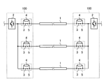
- the power conversion device 100 When the power conversion device 100 according to the first embodiment is applied to a multi-line DC power transmission system interconnected via a plurality of DC lines 1 between two power supply systems, for example, as shown in FIG. What is necessary is just to comprise by connecting the current limiting circuit 5 to the both ends of the DC track 1, respectively. In this case, only the opening / closing device 3 of the current limiting circuit 5 connected to the DC line 1 in which an accident has occurred is opened and current-limited so that the opening / closing device 3 connected to the sound DC line 1 can be controlled open. The operation can be continued without being performed, that is, without causing a power transmission loss due to the current limiting element 4.
- the power conversion device 100 according to the first embodiment is applied to a loop-type multi-terminal DC power transmission system in which a loop is formed by a plurality of DC lines 1, for example, as shown in FIG.
- the current limiting circuit 5 may be connected to each other.
- current limiting circuits 5 may be connected to both ends of each DC line 1.
- only the switching device 3 of the current limiting circuit 5 connected to the DC line 1 in which the accident has occurred is opened to limit the current.
- one or more current limiting circuits 5 are provided between the converter 2 and the DC line 1. Even if an accident occurs at any point on any DC line 1 that forms the DC power transmission system, it is possible to suppress the accident current flowing through the converter 2. 16 to 20, the current limiting circuit 5 is provided at both ends of each DC line 1.
- the present invention can also be applied to a configuration in which a conversion unit for connecting to the switching facility or other power supply system is provided at the point A.
- a two-terminal DC power transmission system As described above, according to the power conversion apparatus of the first embodiment, a two-terminal DC power transmission system, a non-loop type multi-terminal DC power transmission system, a loop type, which are interconnected by connecting a plurality of power supply systems with a DC line.
- one or more current limiting circuits are provided between the converter and the DC line, and when the current flowing through the converter exceeds a threshold lower than the allowable upper limit value of the converter, Since the switchgear connected in parallel with the current limiting element is opened and controlled to be commutated to the current limiting element, when an accident occurs at any point on any DC line forming the DC power transmission system However, the accident current flowing through the converter can be suppressed, and the accident current value when the current interruption is performed by the AC circuit breaker or the DC circuit breaker can be reduced. Also AC circuit breaker Rui can reduce current interruption duty of the DC circuit breaker, the miniaturization of the AC circuit breaker or DC breaker, cost reduction can be achieved.
- the switchgear connected in parallel to the current limiting element with a mechanical switchgear including a circuit breaker, disconnector, or switch, the energization loss during normal DC power transmission can be made extremely small. it can.
- the mechanical switching element by configuring the mechanical switching element with GCB, it is possible to have a configuration that can withstand overvoltage when the GCB is opened.
- a low-rated semiconductor switching element with low conduction loss is connected in series with a mechanical switching element to configure a switching device, and when commutating fault current to a current-limiting element
- the duty of the mechanical switching element can be limited to the duty of voltage interruption, and the mechanical switching element can be an inexpensive switch or disconnector. Or the like.
- the fault current can be immediately commutated to the current limiting element, so that at the time of current interruption of the AC breaker or DC breaker The current value can be further reduced.
- the current limiting element is composed of a superconducting current limiter, a saturable reactor, or a semiconductor switch element, and in normal operation where normal DC power transmission is performed, the current limiting element is set to a low impedance, and the current limiting element is opened when the switchgear is opened. After the fault current commutes, the fault current flowing through the converter is suppressed by setting the current limiting element to high impedance, so that the fault current can be easily commutated with the current limiting element in a low impedance state. It can be carried out.
- the superconducting current limiter when the current limiting element is composed of a superconducting current limiter, the superconducting current limiter is kept in a normal conducting state during normal operation with normal DC power transmission and is set to a high impedance state. If the current flower is in a superconducting state and has a low impedance, it is not necessary to maintain the superconducting current limiter in the superconducting state during steady operation, and unnecessary energy loss can be prevented.
- a current limiting circuit is provided at both ends of each DC line, so that switching facilities and other devices at the branch points of the DC line are provided.
- the present invention can also be applied to a configuration including a conversion unit for connecting to a power supply system.
- Embodiment 2 the configuration in which the current limiting circuit is provided between the DC line and the converter has been described. In the present embodiment, the configuration in which the grounding element of the converter is provided with the current limiting circuit will be described.
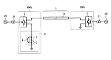
- FIG. 21 is a diagram illustrating an example of a two-terminal DC power transmission system having a neutral wire to which the power conversion device according to the second embodiment is applied.
- FIG. 22 is a diagram illustrating an example of a two-terminal DC power transmission system that does not have a neutral wire to which the power conversion device according to the second embodiment is applied.
- FIG. 23 is a diagram illustrating an example of a two-terminal DC power transmission system including a positive line, a negative line, and a neutral line to which the power conversion device according to the second embodiment is applied.
- the DC line 1 is formed by the positive line 1a and the neutral line 1c, and the grounding element 6 of the converter 2 of the power converter 100a includes the current limiting circuit 5.
- the converter 2 of the power conversion device 100b is grounded via the neutral wire 1c, and therefore it is not necessary to include the current limiting circuit 5.
- the DC line 1 is formed only by the positive electrode line 1a, and the grounding element 6 of the converter 2 of the power converter 100a is provided with the current limiting circuit 5.
- the accident electric current which flows into the converter 2 of each power converter device 100a, 100b can be suppressed.
- the DC line 1 is formed by the positive electrode line 1a, the negative electrode line 1b, and the neutral line 1c, and the grounding element 6 of the converter 2 of the power conversion device 100c is connected to the ground element 6 in the same manner as the example shown in FIG.
- the current limiting circuit 5 is provided. Also in this configuration, the converter 2 of the power conversion device 100d is grounded via the neutral line 1c as in the example shown in FIG. 21, and therefore it is not necessary to include the current limiting circuit 5.
- a threshold for the current flowing through the converter 2 is set as a trigger for controlling the opening / closing device 3 to open, and the current flowing through the converter 2 is set. When this value exceeds this threshold value, the opening / closing device 3 is controlled to be opened and commutated to the current limiting element 4.
- this threshold By setting this threshold to a value lower than the allowable current upper limit value of the converter 2, when a ground fault occurs in the DC line 1, the accident current flowing through the converter 2 is suppressed, and an AC circuit breaker or DC The current flowing through the converter 2 is prevented from exceeding the allowable current upper limit value of the converter 2 until the current is interrupted by the circuit breaker.
- the switching device 3 is controlled to open and commutated to the current limiting element 4, so that the current flowing through the converter 2 exceeds the allowable current upper limit value of the converter 2. Can be made longer. That is, it is possible to prevent the current flowing through the converter 2 from exceeding the allowable current upper limit value of the converter 2 until the current is interrupted by the AC circuit breaker or the DC circuit breaker.
- the switchgear 3 is constituted by a circuit breaker, a disconnector, or a mechanical switch element 3a including a switch (see FIG. 8), so that conversion when performing normal DC power transmission is performed. It is possible to stabilize the ground potential of the device 2.
- the mechanical switching element 3a by configuring the mechanical switching element 3a with GCB, it is possible to have a configuration that can withstand overvoltage when the GCB is opened.
- a low-rated semiconductor switching element 3b with low conduction loss is connected in series with the mechanical switching element 3a to form the switching device 3 (see FIG. 9), and a fault current limiting element.
- the duty of the mechanical switching element 3a can be limited to the voltage cutoff duty by controlling the semiconductor switching element 3b to be turned off and then opening the mechanical switching element 3a.
- the mechanical opening / closing element 3a can be constituted by an inexpensive switch or disconnector.
- the fault current can be immediately commutated to the current limiting element 4, and when the AC breaker or the DC breaker is interrupted The current value at can be further reduced.
- the current limiting element 4 can be configured by the reactor 4a, the resistor 4b, the superconducting current limiter 4c, the saturable reactor 4d, or the semiconductor switching element 4e. Is composed of a superconducting current limiting device 4c, a saturable reactor 4d, or a semiconductor switching device 4e, the current limiting device 4 is set to a low impedance during normal operation for normal DC power transmission, and the switching device 3 is opened. After the fault current commutates to the current limiting element 4, by setting the superconducting current limiter 4c to a high impedance, the fault current can be easily commutated with the current limiting element 4 in a low impedance state.
- the current limiting element 4 is composed of the superconducting current limiter 4c
- the normal state of the direct current power transmission is set to a high impedance with the superconducting current limiter 4c in the normal conducting state, and an accident occurrence of the DC line 1 is caused. If it is detected and the superconducting fault current limiter 4c is set in a superconducting state to have a low impedance, it is not necessary to maintain the superconducting current limiter 4c in the superconducting state during steady operation, thereby preventing unnecessary energy loss. Can do.
- the configuration of the power conversion apparatus 100 according to the present embodiment is similar to that of the first embodiment, in addition to the above-described two-terminal DC power transmission system, non-loop type multi-terminal DC power transmission system, or loop type multi-terminal DC power transmission.
- the grounding element 6 of the converter 2 is provided with the current limiting circuit 5 so that any point on any DC line 1 forming the DC power transmission system can be grounded. Even in the event of an entanglement accident, it is possible to suppress the accident current flowing through the converter 2.
- a two-terminal DC power transmission system a non-loop type multi-terminal DC power transmission system, a loop type, which are interconnected by connecting a plurality of power supply systems with a DC line.
- a grounding element of the converter is equipped with a current limiting circuit, and when the current flowing through the converter exceeds a threshold value lower than the allowable current upper limit value of the converter, it is connected in parallel with the current limiting element. Since the open / closed switch is controlled to open and commutated to the current limiting element, the converter can be used even if a ground fault occurs at any point on any DC line forming the DC power transmission system.
- the current limiting circuit is not provided as in the first embodiment.
- conventional configuration Flow breaker or can reduce the current interruption duty of the DC circuit breaker, the miniaturization of the AC circuit breaker or DC breaker, cost reduction can be achieved.
- the switching device connected in parallel to the current limiting element is configured by a mechanical switching element including a circuit breaker, a disconnector, or a switch, thereby performing normal DC power transmission.
- the energization loss can be extremely reduced.
- the mechanical switching element by configuring the mechanical switching element with GCB, it is possible to have a configuration that can withstand overvoltage when the GCB is opened.
- a low-rated semiconductor switch element having a small conduction loss as in the case of the mechanical switching element is connected in series with the mechanical switching element to constitute a switching device, and to the fault current limiting element.
- the mechanical switching element is controlled to open, thereby limiting the duty of the mechanical switching element to the voltage cutoff duty.
- the semiconductor switch element by configuring the semiconductor switch element with an IGBT or a GCT thyristor capable of high-speed operation, the fault current can be immediately commutated to the current limiting element.
- the current value at the time of current interruption of the DC circuit breaker can be further reduced.
- the current limiting element is composed of a superconducting current limiter, a saturable reactor, or a semiconductor switch element, and during normal operation for normal DC power transmission, the current limiting element is set to a low impedance. After the fault current commutates to the current limiting element when the switchgear is opened, the fault current flowing to the converter is suppressed by setting the current limiting element to a high impedance, so that the current limiting element is in a low impedance state. Accident current can be easily commutated.
- the superconducting current limiter when the current limiting element is composed of a superconducting current limiter, the superconducting current limiter is kept in a normal conducting state during normal operation with normal DC power transmission and is set to a high impedance state. If the current flower is in a superconducting state and has a low impedance, it is not necessary to maintain the superconducting current limiter in the superconducting state during steady operation, and unnecessary energy loss can be prevented.
- the configuration shown in the above embodiment is an example of the configuration of the present invention, and can be combined with another known technique, and a part thereof is omitted without departing from the gist of the present invention. Needless to say, it is possible to change the configuration.
- the power conversion device is useful for a DC power transmission system in which a plurality of power supply systems are connected by a DC line and connected to each other. This is suitable as a technique for suppressing current loss during direct current power transmission while reducing the size and cost.
Landscapes
- Engineering & Computer Science (AREA)
- Power Engineering (AREA)
- Emergency Protection Circuit Devices (AREA)
- Rectifiers (AREA)
- Supply And Distribution Of Alternating Current (AREA)
- Direct Current Feeding And Distribution (AREA)
Abstract
La présente invention concerne un dispositif de conversion de puissance utilisé dans un système de transmission de puissance à courant continu. Dans ce dispositif, plusieurs systèmes d'alimentation électrique sont connectés entre à l'aide d'une ligne à courant continu et sont interconnectés les uns avec les autres ; ces systèmes sont capables d'empêcher la circulation d'un courant accidentel tout en supprimant une perte de transmission d'électricité en temps normal. Les dimensions de l'équipement n'en sont pas augmentées pour autant, ni de même son coût. Le dispositif de conversion de puissance comprend : un convertisseur (2), servant à réaliser une conversion de puissance entre des systèmes d'alimentation électrique (20-1, 20-2) et un système de transmission de puissance à courant continu ; et un circuit de limitation de courant (5), disposé entre le convertisseur (2) et une ligne à courant continu (1), et constitué d'un élément de limitation de courant (4) et d'un dispositif d'ouverture et de fermeture (3) connecté en parallèle avec l'élément de limitation de courant (4). Lorsque le courant circulant à travers le convertisseur (2) dépasse une valeur de seuil qui est inférieure à la valeur de limite supérieure de courant admissible du convertisseur (2), une commande ouvre le dispositif d'ouverture et de fermeture (3).
Priority Applications (2)
| Application Number | Priority Date | Filing Date | Title |
|---|---|---|---|
| PCT/JP2013/055435 WO2014132396A1 (fr) | 2013-02-28 | 2013-02-28 | Dispositif de conversion de puissance |
| JP2013523804A JPWO2014132396A1 (ja) | 2013-02-28 | 2013-02-28 | 電力変換装置 |
Applications Claiming Priority (1)
| Application Number | Priority Date | Filing Date | Title |
|---|---|---|---|
| PCT/JP2013/055435 WO2014132396A1 (fr) | 2013-02-28 | 2013-02-28 | Dispositif de conversion de puissance |
Publications (1)
| Publication Number | Publication Date |
|---|---|
| WO2014132396A1 true WO2014132396A1 (fr) | 2014-09-04 |
Family
ID=51427697
Family Applications (1)
| Application Number | Title | Priority Date | Filing Date |
|---|---|---|---|
| PCT/JP2013/055435 Ceased WO2014132396A1 (fr) | 2013-02-28 | 2013-02-28 | Dispositif de conversion de puissance |
Country Status (2)
| Country | Link |
|---|---|
| JP (1) | JPWO2014132396A1 (fr) |
| WO (1) | WO2014132396A1 (fr) |
Cited By (10)
| Publication number | Priority date | Publication date | Assignee | Title |
|---|---|---|---|---|
| JP6042041B1 (ja) * | 2016-02-05 | 2016-12-14 | 三菱電機株式会社 | 直流遮断器 |
| WO2019043777A1 (fr) * | 2017-08-29 | 2019-03-07 | 株式会社東芝 | Système de transmission de puissance cc |
| JP2019054580A (ja) * | 2017-09-13 | 2019-04-04 | 東芝三菱電機産業システム株式会社 | 電力変換装置 |
| CN110048427A (zh) * | 2019-04-03 | 2019-07-23 | 国网浙江省电力有限公司电力科学研究院 | 一种多端柔性直流配电网潮流保护定值计算方法 |
| WO2019219217A1 (fr) * | 2018-05-18 | 2019-11-21 | Siemens Aktiengesellschaft | Surveillance d'une transmission d'un courant continu à haute tension |
| KR102175998B1 (ko) * | 2019-07-15 | 2020-11-06 | 성균관대학교산학협력단 | 전력용 반도체형 한류기를 이용한 멀티 터미널 직류 배전계통의 보호 방법, 장치 및 시스템 |
| CN112771745A (zh) * | 2018-10-01 | 2021-05-07 | 三菱电机株式会社 | 直流配电系统 |
| WO2023175984A1 (fr) * | 2022-03-18 | 2023-09-21 | 日本電信電話株式会社 | Dispositif de prévention de courant d'appel, dispositif de commande, et procédé de prévention de courant d'appel |
| JP7418671B1 (ja) * | 2023-03-16 | 2024-01-19 | 三菱電機株式会社 | 直流遮断器 |
| WO2024261956A1 (fr) * | 2023-06-22 | 2024-12-26 | 三菱電機株式会社 | Système de distribution d'énergie |
Citations (4)
| Publication number | Priority date | Publication date | Assignee | Title |
|---|---|---|---|---|
| JPS5911738A (ja) * | 1982-07-12 | 1984-01-21 | 関西電力株式会社 | 自動再閉路装置 |
| JPH0578146U (ja) * | 1991-09-24 | 1993-10-22 | 日新電機株式会社 | 限流しゃ断器 |
| JPH0670457A (ja) * | 1992-08-17 | 1994-03-11 | Mitsubishi Electric Corp | 電流制限回路 |
| JP2001178148A (ja) * | 1999-12-16 | 2001-06-29 | Mitsubishi Electric Corp | 自励式変換器の保護装置 |
Family Cites Families (1)
| Publication number | Priority date | Publication date | Assignee | Title |
|---|---|---|---|---|
| JP3445989B2 (ja) * | 1997-08-04 | 2003-09-16 | 株式会社日立製作所 | 直流送電システム |
-
2013
- 2013-02-28 WO PCT/JP2013/055435 patent/WO2014132396A1/fr not_active Ceased
- 2013-02-28 JP JP2013523804A patent/JPWO2014132396A1/ja active Pending
Patent Citations (4)
| Publication number | Priority date | Publication date | Assignee | Title |
|---|---|---|---|---|
| JPS5911738A (ja) * | 1982-07-12 | 1984-01-21 | 関西電力株式会社 | 自動再閉路装置 |
| JPH0578146U (ja) * | 1991-09-24 | 1993-10-22 | 日新電機株式会社 | 限流しゃ断器 |
| JPH0670457A (ja) * | 1992-08-17 | 1994-03-11 | Mitsubishi Electric Corp | 電流制限回路 |
| JP2001178148A (ja) * | 1999-12-16 | 2001-06-29 | Mitsubishi Electric Corp | 自励式変換器の保護装置 |
Cited By (18)
| Publication number | Priority date | Publication date | Assignee | Title |
|---|---|---|---|---|
| WO2017134825A1 (fr) * | 2016-02-05 | 2017-08-10 | 三菱電機株式会社 | Disjoncteur à courant continu |
| JP6042041B1 (ja) * | 2016-02-05 | 2016-12-14 | 三菱電機株式会社 | 直流遮断器 |
| WO2019043777A1 (fr) * | 2017-08-29 | 2019-03-07 | 株式会社東芝 | Système de transmission de puissance cc |
| JP2019054580A (ja) * | 2017-09-13 | 2019-04-04 | 東芝三菱電機産業システム株式会社 | 電力変換装置 |
| US11177662B2 (en) | 2018-05-18 | 2021-11-16 | Siemens Energy Global GmbH & Co. KG | Monitoring of a high-voltage DC transmission |
| WO2019219217A1 (fr) * | 2018-05-18 | 2019-11-21 | Siemens Aktiengesellschaft | Surveillance d'une transmission d'un courant continu à haute tension |
| CN112154588B (zh) * | 2018-05-18 | 2022-01-14 | 西门子能源全球有限公司 | 监视高压直流输电 |
| CN112154588A (zh) * | 2018-05-18 | 2020-12-29 | 西门子股份公司 | 监视高压直流输电 |
| CN112771745B (zh) * | 2018-10-01 | 2023-08-25 | 三菱电机株式会社 | 直流配电系统 |
| CN112771745A (zh) * | 2018-10-01 | 2021-05-07 | 三菱电机株式会社 | 直流配电系统 |
| CN110048427B (zh) * | 2019-04-03 | 2021-06-08 | 国网浙江省电力有限公司电力科学研究院 | 一种多端柔性直流配电网潮流保护定值计算方法 |
| CN110048427A (zh) * | 2019-04-03 | 2019-07-23 | 国网浙江省电力有限公司电力科学研究院 | 一种多端柔性直流配电网潮流保护定值计算方法 |
| KR102175998B1 (ko) * | 2019-07-15 | 2020-11-06 | 성균관대학교산학협력단 | 전력용 반도체형 한류기를 이용한 멀티 터미널 직류 배전계통의 보호 방법, 장치 및 시스템 |
| WO2023175984A1 (fr) * | 2022-03-18 | 2023-09-21 | 日本電信電話株式会社 | Dispositif de prévention de courant d'appel, dispositif de commande, et procédé de prévention de courant d'appel |
| JPWO2023175984A1 (fr) * | 2022-03-18 | 2023-09-21 | ||
| JP7418671B1 (ja) * | 2023-03-16 | 2024-01-19 | 三菱電機株式会社 | 直流遮断器 |
| WO2024189891A1 (fr) * | 2023-03-16 | 2024-09-19 | 三菱電機株式会社 | Disjoncteur cc |
| WO2024261956A1 (fr) * | 2023-06-22 | 2024-12-26 | 三菱電機株式会社 | Système de distribution d'énergie |
Also Published As
| Publication number | Publication date |
|---|---|
| JPWO2014132396A1 (ja) | 2017-02-02 |
Similar Documents
| Publication | Publication Date | Title |
|---|---|---|
| WO2014132396A1 (fr) | Dispositif de conversion de puissance | |
| RU2592640C2 (ru) | Линейный защитный автомат постоянного напряжения | |
| KR101453631B1 (ko) | 고전압용 컨버터 | |
| KR101720112B1 (ko) | 선로 전류를 차단 또는 제한하는 장치 및 그의 제어 방법 | |
| CN103972855B (zh) | 一种使线路双向电流分断的装置及其控制方法 | |
| CN105917431B (zh) | 用于切换直流电流的装置 | |
| EP2768102B1 (fr) | Dispositif d'interruption de circuit | |
| JP2016162713A (ja) | 直流遮断装置 | |
| KR20140022374A (ko) | 고전압 dc 라인 상의 고장을 제거하기 위한 방법, 고전압 dc 라인을 통해 전류를 전송하기 위한 시스템, 및 컨버터 | |
| JP7465997B2 (ja) | 固体絶縁スイッチ | |
| JPH11297170A (ja) | 直流消弧方法及び装置 | |
| Shen et al. | Ultrafast autonomous solid state circuit breakers for shipboard DC power distribution | |
| JPWO2013164875A1 (ja) | 直流遮断器 | |
| CN111937110B (zh) | 开关设备 | |
| WO2014117608A1 (fr) | Appareil pour interrompre le courant d'un circuit et procédé de commande de celui-ci | |
| Demetriades et al. | DC-breaker for a multi-megawatt battery energy storage system | |
| CN111712982B (zh) | 故障处理 | |
| EP2849306A1 (fr) | Convertisseur de source de tension | |
| US20180115253A1 (en) | Improvements in or relating to electrical assemblies | |
| CN103650086B (zh) | 开关装置 | |
| US10333313B2 (en) | Electrical assembly | |
| US11539326B2 (en) | Photovoltaic direct-current breaking apparatus | |
| CN104380421B (zh) | 用于在直流电压网中切换的装置 | |
| CN109789789B (zh) | 用于轨道车辆的驱动系统 | |
| CN105896477A (zh) | 一种模块化多电平换流器的接地保护方法及模块化多电平换流器 |
Legal Events
| Date | Code | Title | Description |
|---|---|---|---|
| ENP | Entry into the national phase |
Ref document number: 2013523804 Country of ref document: JP Kind code of ref document: A |
|
| 121 | Ep: the epo has been informed by wipo that ep was designated in this application |
Ref document number: 13876346 Country of ref document: EP Kind code of ref document: A1 |
|
| NENP | Non-entry into the national phase |
Ref country code: DE |
|
| 122 | Ep: pct application non-entry in european phase |
Ref document number: 13876346 Country of ref document: EP Kind code of ref document: A1 |