WO2014132845A1 - Procédé de mesure de forme d'outil et dispositif de mesure de forme d'outil - Google Patents
Procédé de mesure de forme d'outil et dispositif de mesure de forme d'outil Download PDFInfo
- Publication number
- WO2014132845A1 WO2014132845A1 PCT/JP2014/053833 JP2014053833W WO2014132845A1 WO 2014132845 A1 WO2014132845 A1 WO 2014132845A1 JP 2014053833 W JP2014053833 W JP 2014053833W WO 2014132845 A1 WO2014132845 A1 WO 2014132845A1
- Authority
- WO
- WIPO (PCT)
- Prior art keywords
- tool
- machine
- shape
- machining
- holding mechanism
- Prior art date
- Legal status (The legal status is an assumption and is not a legal conclusion. Google has not performed a legal analysis and makes no representation as to the accuracy of the status listed.)
- Ceased
Links
Images




Classifications
-
- B—PERFORMING OPERATIONS; TRANSPORTING
- B23—MACHINE TOOLS; METAL-WORKING NOT OTHERWISE PROVIDED FOR
- B23Q—DETAILS, COMPONENTS, OR ACCESSORIES FOR MACHINE TOOLS, e.g. ARRANGEMENTS FOR COPYING OR CONTROLLING; MACHINE TOOLS IN GENERAL CHARACTERISED BY THE CONSTRUCTION OF PARTICULAR DETAILS OR COMPONENTS; COMBINATIONS OR ASSOCIATIONS OF METAL-WORKING MACHINES, NOT DIRECTED TO A PARTICULAR RESULT
- B23Q17/00—Arrangements for observing, indicating or measuring on machine tools
- B23Q17/24—Arrangements for observing, indicating or measuring on machine tools using optics or electromagnetic waves
- B23Q17/2452—Arrangements for observing, indicating or measuring on machine tools using optics or electromagnetic waves for measuring features or for detecting a condition of machine parts, tools or workpieces
- B23Q17/2457—Arrangements for observing, indicating or measuring on machine tools using optics or electromagnetic waves for measuring features or for detecting a condition of machine parts, tools or workpieces of tools
-
- B—PERFORMING OPERATIONS; TRANSPORTING
- B23—MACHINE TOOLS; METAL-WORKING NOT OTHERWISE PROVIDED FOR
- B23Q—DETAILS, COMPONENTS, OR ACCESSORIES FOR MACHINE TOOLS, e.g. ARRANGEMENTS FOR COPYING OR CONTROLLING; MACHINE TOOLS IN GENERAL CHARACTERISED BY THE CONSTRUCTION OF PARTICULAR DETAILS OR COMPONENTS; COMBINATIONS OR ASSOCIATIONS OF METAL-WORKING MACHINES, NOT DIRECTED TO A PARTICULAR RESULT
- B23Q17/00—Arrangements for observing, indicating or measuring on machine tools
- B23Q17/24—Arrangements for observing, indicating or measuring on machine tools using optics or electromagnetic waves
- B23Q17/248—Arrangements for observing, indicating or measuring on machine tools using optics or electromagnetic waves using special electromagnetic means or methods
- B23Q17/249—Arrangements for observing, indicating or measuring on machine tools using optics or electromagnetic waves using special electromagnetic means or methods using image analysis, e.g. for radar, infrared or array camera images
-
- G—PHYSICS
- G01—MEASURING; TESTING
- G01B—MEASURING LENGTH, THICKNESS OR SIMILAR LINEAR DIMENSIONS; MEASURING ANGLES; MEASURING AREAS; MEASURING IRREGULARITIES OF SURFACES OR CONTOURS
- G01B11/00—Measuring arrangements characterised by the use of optical techniques
- G01B11/24—Measuring arrangements characterised by the use of optical techniques for measuring contours or curvatures
- G01B11/25—Measuring arrangements characterised by the use of optical techniques for measuring contours or curvatures by projecting a pattern, e.g. one or more lines, moiré fringes on the object
- G01B11/2518—Projection by scanning of the object
- G01B11/2522—Projection by scanning of the object the position of the object changing and being recorded
Definitions
- the present invention relates to a tool shape measuring method and a tool shape measuring device.
- it is suitable for application to a processing tool used in a machine tool.
- Patent Document 1 Patent Document 2, Patent Document 3, and Patent Document 4.
- the relative positional relationship between the processing tool and the measuring device is constant, and shape measurement is realized using a mathematical calculation formula, which is complicated.
- no specific method is specified for on-machine measurement (measurement with a machining tool mounted on the spindle of a machine tool and similar conditions).
- a camera 04 such as a CCD or CMOS sensor is positioned with respect to a processing tool 03 attached to the ram 01 via a holder 02, and the processing tool 03 or the holder 02 is photographed by the camera 04. Then, the photographed data is subjected to image processing by the image processing device 05, and the data (three-dimensional shape of the tool) obtained by the image processing is stored in the storage device 06, and the three-dimensional shape of the tool stored in the storage device 06 is stored. Based on this, the NC device 07 is to control the machine tool.
- JP-A-8-52638 Japanese Patent No. 3958815 Patent No. 5001521 JP 2012-168186 A
- the present invention has been made in view of the above problems, and an object of the present invention is to provide a tool shape measuring method which is a specific method for on-machine measurement of a processing tool used in a machine tool.
- a tool shape measuring method for solving the above-described problems is a line laser for irradiating a slit-shaped laser to a processing tool or a tool holding mechanism for holding the processing tool, and the line laser.
- a measurement unit comprising a camera for photographing the cutting tool or the cutting surface of the tool holding mechanism by the laser
- the cutting surface 2 In the tool shape measuring method for measuring a dimensional shape, the measurement unit is fixed to a machine tool or a peripheral device thereof, while the processing tool or the tool holding mechanism is moved by a moving means by the machine tool or the peripheral device. It is characterized by being moved by scanning.
- a tool shape measuring method for solving the above-mentioned problems is that, in the first aspect, the measuring unit is mounted on a column of the machine tool, while the Z or Y axis direction of the machine tool is used.
- the processing tool is moved by scanning by a moving means.
- the measurement unit is fixed to the automatic tool changer as the peripheral device, and the tool change operation of the automatic tool changer
- the processing tool is characterized by being moved by scanning.
- the tool shape measuring method according to claim 4 of the present invention that solves the above-described problem is characterized in that the tool holding mechanism is an attachment interposed between the machining tool and a spindle of the machine tool. .
- a tool shape measuring apparatus for solving the above-described problems is irradiated with a line laser that irradiates a slit-shaped laser to a processing tool or a tool holding mechanism that holds the processing tool, and the line laser.
- a measurement unit comprising a camera for photographing the cutting tool or the cutting surface of the tool holding mechanism by the laser
- the cutting surface 2 In the tool shape measuring apparatus for measuring a dimensional shape, the measurement unit is fixed to a machine tool or a peripheral device thereof, while the processing tool or the tool holding mechanism is moved by a moving means by the machine tool or the peripheral device. It is characterized by being moved by scanning.
- a tool shape measuring apparatus for solving the above-mentioned problems is the tool shape measuring apparatus according to the fifth aspect, wherein the measuring unit is mounted on a column of the machine tool, while the Z-axis or Y-axis direction of the machine tool.
- a tool shape measuring apparatus wherein the machining tool is moved by scanning by a moving means.
- a tool shape measuring apparatus for solving the above-mentioned problems is the tool shape measuring apparatus according to the fifth aspect, wherein the measuring unit is fixed to the automatic tool changing apparatus that is the peripheral device.
- a tool shape measuring apparatus wherein the machining tool is moved by scanning by a tool change operation.
- the tool shape measuring apparatus according to an eighth aspect of the present invention for solving the above-described problems is the tool shape measuring apparatus according to the fifth aspect, wherein the tool holding mechanism is an attachment interposed between the machining tool and a spindle of the machine tool.
- the tool shape measuring apparatus characterized by the above-mentioned.
- the measuring unit is fixed to the machine tool or its peripheral equipment, measurement on the machine, that is, a state in which the machining tool is mounted on the spindle of the machine tool
- measurement on the machine that is, a state in which the machining tool is mounted on the spindle of the machine tool
- As a tool shape it is possible to substitute a tool length measurement.
- the tool shape measuring method of the second aspect of the present invention since the scanning operation is performed by moving the Z-axis or the Y-axis of the machine tool, there is an effect that high-speed measurement is possible.
- the tool shape measuring method of the third aspect of the present invention there is an effect that measurement on the machine, that is, measurement in a state held by the automatic tool changer is possible.
- the tool shape measuring method according to claim 4 of the present invention there is an effect that the shape of the attachment interposed between the machining tool and the main spindle of the machine tool can be measured.
- the measuring unit is fixed to the machine tool or its peripheral equipment, measurement on the machine, that is, a state in which the machining tool is mounted on the spindle of the machine tool
- measurement on the machine that is, a state in which the machining tool is mounted on the spindle of the machine tool
- As a tool shape it is possible to substitute a tool length measurement.
- the tool shape measuring apparatus of the sixth aspect of the present invention since the scanning operation is performed by moving the Z axis or the Y axis of the machine tool, there is an effect that high speed measurement is possible.
- the tool shape measuring apparatus of the seventh aspect of the present invention there is an effect that measurement on the machine, that is, measurement in a state held by the automatic tool changer is possible. According to the tool shape measuring apparatus of the eighth aspect of the present invention, there is an effect that the shape of the attachment interposed between the processing tool and the main spindle of the machine tool can be measured.
- FIG. 1 is a perspective view of a machine tool to which a tool shape measuring method according to a first embodiment of the present invention is applied. It is a block diagram for implement
- FIG. 1 is a schematic diagram showing a light cutting method which is a premise of the present invention.
- a slit laser is irradiated from a line laser 2 onto a measurement target 1, and the cut surface of the measurement target 1 of the laser by the line laser 2 is changed to a line.
- the image is taken by the camera 3 from an angle different from that of the laser 2, the object 1 to be measured is scanned and moved relative to the line laser 2 and the camera 3, and the two-dimensional shape by the cut surface is measured. Furthermore, the obtained two-dimensional shape is developed in the movement direction to measure the three-dimensional shape.
- the present invention applies such a light cutting method.
- a slit laser is irradiated from a line laser 12 to a processing tool 11 mounted on a spindle 10 of a machine tool
- a camera 13 such as a CCD or CMOS sensor from an angle different from that of the line laser 12
- the line laser 12 and the camera 13 in the present invention, the line
- the measuring unit including the laser 12 and the camera 13 is fixed to a column or the like of the machine tool), and the machining tool 11 is scanned by the axis moving function of the machine tool.
- the two-dimensional shape of the processing tool 11 acquired by the camera 13 is image-processed by the image processing device 14, and the two-dimensional shape data of the processing tool 11 obtained by the image processing and the two-dimensional shape are scanned by the processing tool 11.
- Three-dimensional shape data obtained by expanding in the moving direction is stored in the storage device 15, and the NC device 16 operates the machine tool based on these two-dimensional shape or three-dimensional shape data stored in the storage device 15. .
- a typical portal machine tool 100 as a machine tool is shown in FIG.
- a portal machine tool 100 shown in FIG. 3 includes a table 110 on which a workpiece is placed and moved in the front-rear direction (X-axis direction), columns 120 erected on the left and right of the table 110, and on these columns 120.
- a cross rail 130 provided across, a saddle 140 movable in the horizontal direction (Y-axis direction) on the cross rail 130, and a ram 150 movable in the vertical direction (Z-axis direction) with respect to the saddle 140.
- the machining tool 11 is mounted on the main shaft of the ram 150.
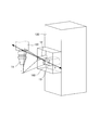
- a measurement unit 160 including the line laser 12 and the camera 13 is fixed to the column 120. Accordingly, with the measuring unit 160 fixed to the column 120, the line laser 12 irradiates a slit-shaped laser onto the machining tool 11 mounted on the main shaft, and the camera 13 shows the cut surface of the machining tool 11 with the slit-shaped laser.
- the two-dimensional movement of the machining tool 11 is performed by scanning the machining tool 11 with the axis movement function of the machine tool, that is, the Y-axis direction or Z-axis direction moving means by the saddle 140 or the ram 150.
- the shape can be measured, and the two-dimensional shape is developed in the scanning movement direction of the processing tool 11 so that the three-dimensional shape of the processing tool 11 can be measured.
- an automatic tool changer is generally provided as a peripheral device in a machine tool. Also in FIG. 3, an ATC magazine 220 for storing a plurality of machining tools is located on the side of the column 120. is doing. The automatic tool changer rotates a plurality of machining tools stored in the ATC magazine 220 with a chain, and moves the machining tool that has reached the tool change position to the spindle of the machine tool with an ATC arm (changer) (not shown). Are attached and removed.
- ATC automatic tool changer
- the machining tool 11 can be scanned and moved by using the tool changing operation of the automatic tool changing device instead of the axis moving function of the machine tool.
- a measuring unit 160 including a line laser 12 and a camera 13 is fixed to a column 120 of the machine tool.
- a portal machine tool 100 shown in FIG. 3 is used, and a processing tool 11 is mounted on the main shaft of the ram 150.
- the line laser 12 irradiates the machining tool 11 mounted on the main shaft of the ram 150 with a substantially horizontal slit-shaped laser, and the machining tool 11 using the slit-shaped laser from an angle different from the line laser 12.
- the processing tool 11 is scanned and moved in the Z-axis direction (up and down direction) indicated by an arrow in the figure while the cut surface is photographed by the camera 13.
- the camera 13 acquires a plurality of two-dimensional images along the Z-axis direction by the horizontal cut surface of the processing tool 11.
- an image processing device 14, a storage device 15, an NC device 16, a machine interference check system 17, and a tool shape check system 18 are connected to the line laser 12 and the camera 13.
- the image processing device 14 performs image processing on the two-dimensional image of the machining tool 11 obtained by the cut surface acquired by the camera 13 to obtain two-dimensional shape data of the machining tool 11, and further develops the two-dimensional image in the Z-axis direction. Then, the three-dimensional shape data of the processing tool 11 is used, and the two-dimensional shape data and the three-dimensional shape data are sent to the storage device 15.
- the storage device 15 stores the two-dimensional shape data and the three-dimensional shape data image-processed by the image processing device 14, and the two-dimensional shape data or the three-dimensional shape data is stored in the NC device 16, the machine interference check system 17, the tool shape. Send to check system 18.
- the NC device 16 has a coordinate position (X axis, Y axis, Z axis) of the machine tool, tool information (tool length, tool diameter, etc.), and a machining program to be executed.
- the coordinate position of the machine tool is output, and the tool information is output to the tool shape check system 18.
- the machine interference check system 17 includes a storage device 20 that stores the three-dimensional shape of the workpiece, and uses the machine coordinate position (X axis, Y axis, Z axis) and the three-dimensional shape data of the workpiece. While performing the cutting simulation with the machining tool, the interference between the machine and the machining tool and the workpiece and the interference between the machine, the machining tool and the jig are checked.
- the jig is a mechanism for holding the workpiece against the machine tool.
- the tool shape check system 18 checks whether the tool data (tool length, tool diameter, etc.) inside the NC device 16 used for machining and the two-dimensional or three-dimensional shape data of the machining tool stored in the storage device 15 are the same. To do.
- the NC device 16 controls the machine tool based on the check results of the machine interference check system 17 and the tool shape check system 18.
- FIG. 6 shows a flow of processing in the tool shape measuring method according to the present embodiment.
- automatic tool change is executed (step S1). That is, the machining tool 11 stored in the ATC magazine 220 is moved to the tool change position by the automatic tool changer.
- the machining tool 11 that has reached the tool change position is mounted on the spindle of the machine tool (step S2).
- step S3 the processing tool 11 mounted on the spindle is moved to the measurement start position (step S3). Thereafter, scanning is started (step S4). That is, while irradiating the processing tool 11 with a slit-shaped laser from the laser sensor, the cutting tool 11 is moved to Z by the axis moving function of the machine tool while photographing the cutting surface of the processing tool 11 with the slit-shaped laser. Move it in the axial direction. Although the present embodiment is in the Z-axis direction, the second embodiment is moved in the Y-axis direction.
- step S5 When the movement of the machining tool 11 in the Z-axis (or Y-axis) direction is completed (step S5), scanning is also completed (step S6). After the scanning is completed, the two-dimensional image of the processing tool 11 acquired by the camera is image-processed to generate two-dimensional shape data, and the two-dimensional shape data is developed in the scanning direction of the processing tool 11 to obtain the three-dimensional shape data. Is created (step S7).
- the machine interference check system 17 checks the interference between the machine and the machining tool and the workpiece, and the interference between the machine, the machining tool and the jig, and the tool shape check system 18 performs the machining. It is checked whether the tool data inside the NC device used in step 2 and the two-dimensional or three-dimensional shape data of the machining tool stored in the storage device 15 are the same.
- the measurement unit 160 is fixed to the column 120 of the machine tool, so measurement on the machine is possible, Measurement in an actual machining state, that is, measurement in a state where the machining tool 11 is mounted on the spindle of the machine tool is possible.
- the measurement is performed by the line laser 12 and the camera 13, high-precision tool shape measurement is possible. Furthermore, since the machining tool 11 is scanned by the Z-axis movement of the machine tool, high-speed movement is possible, and a moving device for measuring equipment is not required.
- the shape of the attachment can be measured, and further, the tool length can be substituted as the tool shape.
- a tool shape measuring method according to the second embodiment of the present invention will be described with reference to FIG.
- a measuring unit 160 comprising a line laser 12 and a camera 13 is fixed to a column 120 of the machine tool.
- a portal machine tool 100 shown in FIG. 3 is used, and a processing tool 11 is mounted on the main shaft of the ram 150.
- the line laser 12 irradiates the machining tool 11 mounted on the main shaft of the column 120 with a slit-shaped laser directed in the vertical direction, and machining by the slit-shaped laser from an angle different from the line laser 12. While the cut surface of the tool 11 is photographed by the camera 13, the machining tool 11 is moved in the Y-axis direction (horizontal direction) indicated by an arrow in the figure.
- the camera 13 acquires a plurality of two-dimensional images along the Y-axis direction by the cut surface in the vertical direction of the processing tool 11.
- the two-dimensional image of the cut surface acquired by the camera 13 is obtained from the two-dimensional shape data of the processing tool 11 by the image processing device 14. Furthermore, the two-dimensional image is developed in the Y-axis direction to become the three-dimensional shape data of the processing tool 11.
- the created two-dimensional shape or three-dimensional shape data is stored in the storage device 15, while being sent to the NC device 16, the machine interference check system 17, and the tool shape check system 18.
- the machine interference check system 17 checks the interference between the machine and the machining tool and the workpiece, and the interference between the machine, the machining tool and the jig, and the tool shape check system 18 includes the tool data inside the NC device used for machining. It is checked whether the two-dimensional or three-dimensional shape data of the machining tool stored in the storage device 15 is the same.
- the measurement unit 160 is fixed to the column 120 of the machine tool, so measurement on the machine is possible, Measurement in an actual machining state, that is, measurement in a state where the machining tool 11 is mounted on the spindle of the machine tool is possible. Further, since the measurement is performed by the line laser 12 and the camera 13, high-precision tool shape measurement is possible.
- the machining tool 11 is scanned by the Y-axis movement of the machine tool, high-speed movement is possible, and a moving device for measuring equipment is not required. Further, when the processing tool 11 is attached to the spindle of the machine tool via an attachment, the shape of the attachment can be measured, and further, the tool length can be substituted as the tool shape.
- an automatic tool changer (ATC) 200 which is a peripheral device, is provided at the side of the column 120 of the machine tool.
- ATC automatic tool changer
- As the machine tool a portal machine tool shown in FIG. 3 is used.
- an ATC magazine 220 is provided on a column 120 by a support member 210, and a measurement unit 160 comprising a line laser 12 and a camera 13 is fixed to the support member 210 as shown in FIG. Has been.
- the automatic tool changer 200 is provided with an ATC arm (changer) for attaching and detaching the machining tool 11 accommodated in the ATC magazine 220 and moved to the tool change position to the spindle of the machine tool. It is omitted in the figure.
- the ATC magazine 220 rotates and moves the magazine pot 230 holding the machining tool 11 in the U-axis direction indicated by an arrow in the drawing by an indexing operation by a chain drive, that is, a tool changing operation. is there.
- the processing tool 11 held in the magazine pot 230 moves relative to the measurement unit 160 fixed to the support member 210, and the processing held in the magazine pot 230 from the line laser 12.
- the tool 11 is irradiated with a substantially horizontal slit-shaped laser, and the cut surface of the processing tool 11 by the slit-shaped laser is photographed by the camera 13 from an angle different from that of the line laser 12, and is applied to the magazine pot 230.
- the held processing tool 11 is scanned and moved in the U-axis direction (vertical direction) indicated by an arrow in the drawing.
- the camera 13 acquires a plurality of two-dimensional images by the horizontal cut surface of the processing tool 11 along the U-axis direction.
- the two-dimensional image of the cut surface acquired by the camera 13 is obtained from the two-dimensional shape data of the processing tool 11 by the image processing device 14. Further, the two-dimensional image is developed in the U-axis direction to become three-dimensional shape data of the processing tool 11.
- the created two-dimensional shape or three-dimensional shape data is stored in the storage device 15, while being sent to the NC device 16, the machine interference check system 17, and the tool shape check system 18.
- the machine interference check system 17 checks the interference between the machine and the machining tool and the workpiece, and the interference between the machine, the machining tool and the jig, and the tool shape check system 18 is provided inside the NC device used for machining. It is checked whether the tool data and the two-dimensional or three-dimensional shape data of the machining tool stored in the storage device 15 are the same.
- the flow of processing in the tool shape measuring method according to the present embodiment is the same as that of the first embodiment described above as shown in FIG. Since the position of the machining tool 11 held in the magazine pot 230 is uniquely determined with respect to the machining tool 11 mounted on the spindle of the machine tool, the machine interference check system 17 and the tool shape check system 18 are used. The check can be performed in the same manner as when the machine tool is mounted on the spindle.
- the measurement unit 160 is fixed to the support member 210 of the automatic tool changer 200. It is possible to perform pre-measurement before processing, that is, measurement in a state of being held in the magazine pot 230 is possible. Further, since the measurement is performed by the line laser 12 and the camera 13, high-precision tool shape measurement is possible.
- machining tool 11 is scanned by the indexing operation of the magazine pot 230, high-speed movement is possible, and a moving device for the measuring device is unnecessary. Moreover, substitution of tool length measurement is also possible as a tool shape.
- a tool shape measuring method according to a fourth embodiment of the present invention will be described with reference to FIG.
- a measuring unit 160 including a line laser 12 and a camera 13 is fixed to a column 120 of the machine tool.
- a portal machine tool 100 shown in FIG. 3 is used, and the machining tool 11 is mounted on the main shaft of the ram 150 via the attachment 30.
- the attachment 30 is a tool holding mechanism that holds the processing tool 11 so that the processing tool 11 can be directed at an arbitrary angle.
- the line laser 12 irradiates the attachment 30 with a substantially horizontal slit-shaped laser, and the camera 13 shoots the cut surface of the attachment 30 with the slit-shaped laser from an angle different from that of the line laser 12.
- the attachment 30 is scanned and moved in the Z-axis direction (vertical direction) indicated by an arrow in the drawing.
- the camera 13 acquires a plurality of two-dimensional images along the Z-axis direction by the horizontal cut surface of the attachment 30.
- the two-dimensional image of the cut surface acquired by the camera 13 becomes the two-dimensional shape data of the attachment 30 by the image processing device 14. Furthermore, the two-dimensional image is developed in the Z-axis direction to become the three-dimensional shape data of the attachment 30.
- the created two-dimensional shape or three-dimensional shape data is stored in the storage device 15, while being sent to the NC device 16, the machine interference check system 17, and the tool shape check system 18.
- the machine interference check system 17 checks the interference between the machine and the machining tool and the workpiece, and the interference between the machine, the machining tool and the jig, and the tool shape check system 18 includes attachment data inside the NC device used for machining. It is checked whether the two-dimensional or three-dimensional shape data of the attachment stored in the storage device 15 is the same.
- the measurement unit 160 is fixed to the column 120 of the machine tool, so measurement on the machine is possible, Measurement in an actual machining state, that is, measurement in a state where the attachment 30 is mounted on a machine tool is possible.
- the present invention is widely applicable industrially as a tool shape measuring method and a tool shape measuring device suitable for being applied to a machining tool used in a machine tool.
Landscapes
- Engineering & Computer Science (AREA)
- Physics & Mathematics (AREA)
- Computer Vision & Pattern Recognition (AREA)
- Optics & Photonics (AREA)
- Mechanical Engineering (AREA)
- General Physics & Mathematics (AREA)
- Radar, Positioning & Navigation (AREA)
- Remote Sensing (AREA)
- Electromagnetism (AREA)
- Machine Tool Sensing Apparatuses (AREA)
- Length Measuring Devices By Optical Means (AREA)
Abstract
La présente invention concerne un procédé de mesure de forme d'outil et un dispositif de mesure de forme d'outil. En balayant ou déplaçant de manière relative un outil (11), ou un mécanisme de retenue d'outil (30) qui retient l'outil (11), par rapport à une unité de mesure (160) comprenant un laser en ligne (12) qui expose l'outil (11) ou le mécanisme de retenue d'outil (30) à un faisceau laser de forme fendue et une caméra (13) qui capture une image d'une section transversale de l'outil (11) ou du mécanisme de retenue d'outil (30) formée par ledit faisceau laser émis par le laser en ligne (12), la forme en deux dimensions formées par ladite section transversale est mesurée. L'unité de mesure (160) est fixée à une machine-outil (100) ou à un dispositif périphérique (200) de celle-ci. L'outil (11) ou le mécanisme de retenue d'outil (30) est balayé et déplacé par un moyen mobile de la machine-outil (100) ou du dispositif périphérique (200).
Priority Applications (1)
| Application Number | Priority Date | Filing Date | Title |
|---|---|---|---|
| CN201480003617.7A CN104870143B (zh) | 2013-02-26 | 2014-02-19 | 工具形状测定方法以及工具形状测定装置 |
Applications Claiming Priority (2)
| Application Number | Priority Date | Filing Date | Title |
|---|---|---|---|
| JP2013035367A JP6037891B2 (ja) | 2013-02-26 | 2013-02-26 | 工具形状測定方法及び工具形状測定装置 |
| JP2013-035367 | 2013-02-26 |
Publications (1)
| Publication Number | Publication Date |
|---|---|
| WO2014132845A1 true WO2014132845A1 (fr) | 2014-09-04 |
Family
ID=51428116
Family Applications (1)
| Application Number | Title | Priority Date | Filing Date |
|---|---|---|---|
| PCT/JP2014/053833 Ceased WO2014132845A1 (fr) | 2013-02-26 | 2014-02-19 | Procédé de mesure de forme d'outil et dispositif de mesure de forme d'outil |
Country Status (3)
| Country | Link |
|---|---|
| JP (1) | JP6037891B2 (fr) |
| CN (1) | CN104870143B (fr) |
| WO (1) | WO2014132845A1 (fr) |
Cited By (5)
| Publication number | Priority date | Publication date | Assignee | Title |
|---|---|---|---|---|
| CN107532886A (zh) * | 2015-06-30 | 2018-01-02 | 别格大昭和株式会社 | 工具形状测定装置 |
| WO2019069933A1 (fr) * | 2017-10-06 | 2019-04-11 | ヘキサゴン・メトロジー株式会社 | Appareil d'usinage |
| WO2020108982A1 (fr) * | 2018-11-27 | 2020-06-04 | Inventio Ag | Dispositif de montage et procédé de perçage automatisé de trous dans des parois de bâtiment comprenant la détection automatisée de marques d'usure au niveau du foret |
| CN113899311A (zh) * | 2021-09-29 | 2022-01-07 | 天津大学 | 一种非接触式立铣刀侧刃磨损形貌在机检测实验台及方法 |
| CN114227377A (zh) * | 2022-01-28 | 2022-03-25 | 四川建筑职业技术学院 | 一种光电安装式对刀仪 |
Families Citing this family (16)
| Publication number | Priority date | Publication date | Assignee | Title |
|---|---|---|---|---|
| JP6726439B2 (ja) * | 2014-12-18 | 2020-07-22 | ビアメカニクス株式会社 | 基板穴明け装置及びその制御方法 |
| CN106736867B (zh) * | 2016-11-17 | 2019-08-20 | 天津大学 | 机床主轴双线结构光快速标定方法 |
| JP6829062B2 (ja) * | 2016-11-29 | 2021-02-10 | ヘキサゴン・メトロジー株式会社 | 三次元測定装置 |
| CN106840028A (zh) * | 2016-12-23 | 2017-06-13 | 湖北文理学院 | 刀具磨损的在位测量方法和装置 |
| CN107063109A (zh) * | 2017-04-27 | 2017-08-18 | 重庆都英科技有限公司 | 一种压铸件检测装置 |
| CH713798A1 (de) * | 2017-05-19 | 2018-11-30 | Reishauer Ag | Maschine zur Feinbearbeitung von verzahnten Werkstücken sowie Verfahren zur Vermessung von Kenngrössen eines Feinbearbeitungswerkzeugs. |
| DE102017117840A1 (de) * | 2017-08-07 | 2019-02-07 | Franz Haimer Maschinenbau Kg | Erstellung eines digitalen zwillings in einem bearbeitungszentrum |
| DE102017010322A1 (de) * | 2017-11-08 | 2019-05-09 | Satisloh Ag | Vorrichtung zur Bearbeitung von optischen Werkstücken, insbesondere Brillengläsern |
| KR101878630B1 (ko) | 2018-01-24 | 2018-07-13 | 주식회사 푸름인더스트리 | 영상 기반 머신툴 프리세터 자동화 시스템 |
| CN112105889B (zh) * | 2018-05-08 | 2022-09-20 | 汉阳大学校Erica产学协力团 | 对象物的表面测定装置及测定方法 |
| TWI669484B (zh) * | 2018-10-12 | 2019-08-21 | 財團法人工業技術研究院 | 加工程式與對應之切削刀具之匹配辨識方法與系統 |
| WO2020090844A1 (fr) * | 2018-10-30 | 2020-05-07 | 東芝機械株式会社 | Dispositif de mesure de forme d'outil et procédé de mesure de forme d'outil |
| JP6959285B2 (ja) * | 2019-03-28 | 2021-11-02 | ファナック株式会社 | 制御装置および工作機械 |
| KR102405954B1 (ko) * | 2020-06-19 | 2022-06-08 | 현대위아 주식회사 | 공작 기계의 공구 길이 측정방법 |
| CN113211190B (zh) * | 2021-06-03 | 2022-03-29 | 河南领聚网络科技有限公司 | 一种数控加工中心刀具破损磨损在线检测装置及检测方法 |
| WO2025004546A1 (fr) * | 2023-06-29 | 2025-01-02 | 村田機械株式会社 | Machine de traitement au laser |
Citations (5)
| Publication number | Priority date | Publication date | Assignee | Title |
|---|---|---|---|---|
| US5361308A (en) * | 1992-01-10 | 1994-11-01 | General Motors Corporation | 3-D measurement of cutting tool wear |
| JPH0985584A (ja) * | 1995-09-20 | 1997-03-31 | Toshiba Mach Co Ltd | ツールの許容運動速度検出方法および装置およびプログラム機械装置における使用ツール対応運動速度確認方法および装置 |
| JPH1096616A (ja) * | 1996-07-09 | 1998-04-14 | Fanuc Ltd | 工具チップ欠損検査システム |
| JP2003019645A (ja) * | 2001-07-03 | 2003-01-21 | Okuma Corp | 工作機械用の工具形状検出装置 |
| EP2111947A2 (fr) * | 2008-03-31 | 2009-10-28 | Urban GmbH & Co. Maschinenbau KG | Machine de traitement pour profilés de cadre de porte, respectivement, de fenêtre |
Family Cites Families (7)
| Publication number | Priority date | Publication date | Assignee | Title |
|---|---|---|---|---|
| JPS62267607A (ja) * | 1986-05-16 | 1987-11-20 | Kobe Steel Ltd | 光切断線位置検出方法及び装置 |
| JP2000131032A (ja) * | 1998-10-24 | 2000-05-12 | Hitachi Seiki Co Ltd | 三次元形状計測方法およびその装置 |
| DE102004021254A1 (de) * | 2004-04-30 | 2005-11-24 | P & L Gmbh & Co. Kg | Verfahren zur Vermessung eines Werkzeugs einer Werkzeugmaschine |
| CN101758423A (zh) * | 2008-12-23 | 2010-06-30 | 上海诚测电子科技发展有限公司 | 基于图像识别的旋转刀具状态多参数综合评价方法 |
| US9453716B2 (en) * | 2010-10-22 | 2016-09-27 | Makino Milling Machine Co., Ltd. | Method of measurement and apparatus for measurement of tool dimensions |
| CN102221330B (zh) * | 2011-04-02 | 2012-10-10 | 清华大学 | 间隙磁吸式曲面形貌检测机器人及曲面形貌测量方法 |
| CN102927904A (zh) * | 2012-10-25 | 2013-02-13 | 昆山允可精密工业技术有限公司 | 刀具测量装置 |
-
2013
- 2013-02-26 JP JP2013035367A patent/JP6037891B2/ja not_active Expired - Fee Related
-
2014
- 2014-02-19 WO PCT/JP2014/053833 patent/WO2014132845A1/fr not_active Ceased
- 2014-02-19 CN CN201480003617.7A patent/CN104870143B/zh not_active Expired - Fee Related
Patent Citations (5)
| Publication number | Priority date | Publication date | Assignee | Title |
|---|---|---|---|---|
| US5361308A (en) * | 1992-01-10 | 1994-11-01 | General Motors Corporation | 3-D measurement of cutting tool wear |
| JPH0985584A (ja) * | 1995-09-20 | 1997-03-31 | Toshiba Mach Co Ltd | ツールの許容運動速度検出方法および装置およびプログラム機械装置における使用ツール対応運動速度確認方法および装置 |
| JPH1096616A (ja) * | 1996-07-09 | 1998-04-14 | Fanuc Ltd | 工具チップ欠損検査システム |
| JP2003019645A (ja) * | 2001-07-03 | 2003-01-21 | Okuma Corp | 工作機械用の工具形状検出装置 |
| EP2111947A2 (fr) * | 2008-03-31 | 2009-10-28 | Urban GmbH & Co. Maschinenbau KG | Machine de traitement pour profilés de cadre de porte, respectivement, de fenêtre |
Cited By (9)
| Publication number | Priority date | Publication date | Assignee | Title |
|---|---|---|---|---|
| CN107532886A (zh) * | 2015-06-30 | 2018-01-02 | 别格大昭和株式会社 | 工具形状测定装置 |
| CN107532886B (zh) * | 2015-06-30 | 2020-01-24 | 别格大昭和株式会社 | 工具形状测定装置 |
| WO2019069933A1 (fr) * | 2017-10-06 | 2019-04-11 | ヘキサゴン・メトロジー株式会社 | Appareil d'usinage |
| JP2019069486A (ja) * | 2017-10-06 | 2019-05-09 | ヘキサゴン・メトロジー株式会社 | 加工装置 |
| WO2020108982A1 (fr) * | 2018-11-27 | 2020-06-04 | Inventio Ag | Dispositif de montage et procédé de perçage automatisé de trous dans des parois de bâtiment comprenant la détection automatisée de marques d'usure au niveau du foret |
| CN113899311A (zh) * | 2021-09-29 | 2022-01-07 | 天津大学 | 一种非接触式立铣刀侧刃磨损形貌在机检测实验台及方法 |
| CN113899311B (zh) * | 2021-09-29 | 2023-11-24 | 天津大学 | 一种非接触式立铣刀侧刃磨损形貌在机检测实验台及方法 |
| CN114227377A (zh) * | 2022-01-28 | 2022-03-25 | 四川建筑职业技术学院 | 一种光电安装式对刀仪 |
| CN114227377B (zh) * | 2022-01-28 | 2022-11-01 | 四川建筑职业技术学院 | 一种光电安装式对刀仪 |
Also Published As
| Publication number | Publication date |
|---|---|
| CN104870143B (zh) | 2017-03-15 |
| JP6037891B2 (ja) | 2016-12-07 |
| JP2014163807A (ja) | 2014-09-08 |
| CN104870143A (zh) | 2015-08-26 |
Similar Documents
| Publication | Publication Date | Title |
|---|---|---|
| JP6037891B2 (ja) | 工具形状測定方法及び工具形状測定装置 | |
| TWI583480B (zh) | Three - dimensional laser processing machine | |
| JP6407812B2 (ja) | ワーク原点を取得可能な工作機械制御システムおよびワーク原点設定方法 | |
| JP5372598B2 (ja) | 加工方法及び加工システム | |
| JP2016093872A (ja) | 工作機械の工具補正値の自動設定装置及び自動設定方法 | |
| TWI653112B (zh) | Laser processing device | |
| CN108732994B (zh) | 机床的控制系统 | |
| CN108572625B (zh) | 机床的控制系统 | |
| JP6013139B2 (ja) | 工具長測定方法および工作機械 | |
| JP6709280B2 (ja) | 機械加工モジュール、機械加工モジュールのためのアクセサリ・アセンブリ、及び、機械加工モジュールを始動するための方法 | |
| JP2012053509A (ja) | 数値制御工作機械 | |
| KR101527311B1 (ko) | 공작 기계 | |
| WO2012035883A1 (fr) | Procédé d'usinage | |
| JP2010058239A (ja) | 加工方法 | |
| JP2024039635A (ja) | ツール又はコンプリートツールを測定するためのデバイス、及び、ツール又はコンプリートツールのデジタル画像をコンパイルするための方法 | |
| JP2014013547A (ja) | 加工システムにおける誤差補正装置および方法 | |
| JP5622250B1 (ja) | 較正機能付きワーク加工装置 | |
| JP6538345B2 (ja) | 工作機械のワーク計測装置 | |
| CN108732998B (zh) | 机床的控制系统 | |
| CN112672843A (zh) | 激光加工机 | |
| JP2015131303A (ja) | レーザー加工装置における加工送り機構の作動特性検出方法およびレーザー加工装置 | |
| JP2017124485A (ja) | 工作機械および工具先端位置の補正方法 | |
| JP2010058238A (ja) | 加工方法 | |
| JP5072743B2 (ja) | マイクロマシンおよびマイクロフライスマシン | |
| RU2595197C1 (ru) | Способ настройки положения резца токарного станка |
Legal Events
| Date | Code | Title | Description |
|---|---|---|---|
| 121 | Ep: the epo has been informed by wipo that ep was designated in this application |
Ref document number: 14757290 Country of ref document: EP Kind code of ref document: A1 |
|
| NENP | Non-entry into the national phase |
Ref country code: DE |
|
| 122 | Ep: pct application non-entry in european phase |
Ref document number: 14757290 Country of ref document: EP Kind code of ref document: A1 |